Embed Size (px)
Citation preview

PREMIER M PLUS INSTALLATION MANUAL
Approved Document No: GLT.MAN-111 Issue : 2.8 Author: NJ Date: 23/07/2012
8-24 ZONE CONVENTIONAL FIRE ALARM PANEL
INSTALLATION MANUAL
PREMIER M PLUS INSTALLATION MANUAL
Approved Document No: GLT.MAN-111 PAGE 1
Issue : 2.8 Author: NJ Date: 23/07/2012
PREMIER M PLUS OVERVIEW
The Premier M plus is a medium size conventional panel from Zeta Alarm Systems. Its Features include:-
Designed to EN54 Parts 2 & 4.
It is available in 8 ,16 or 24 zones sizes.
Automatically uses diode bases for line continuity.
Four common sounder circuits (400mA Each).
Serial Repeater Output.
Fire & Fault Relays (SELV).
Fire Alarm Routing Equipment (F.A.R.E.) Output (which can be disabled).
Auxiliary supply (29 Volts, 250 mA).
Zone & Sounder Disablement facility.
Test mode.
Sounder delay facility.
5 amp power supply.
PREMIER M PLUS INSTALLATION MANUAL
Approved Document No: GLT.MAN-111 PAGE 2
Issue : 2.8 Author: NJ Date: 23/07/2012
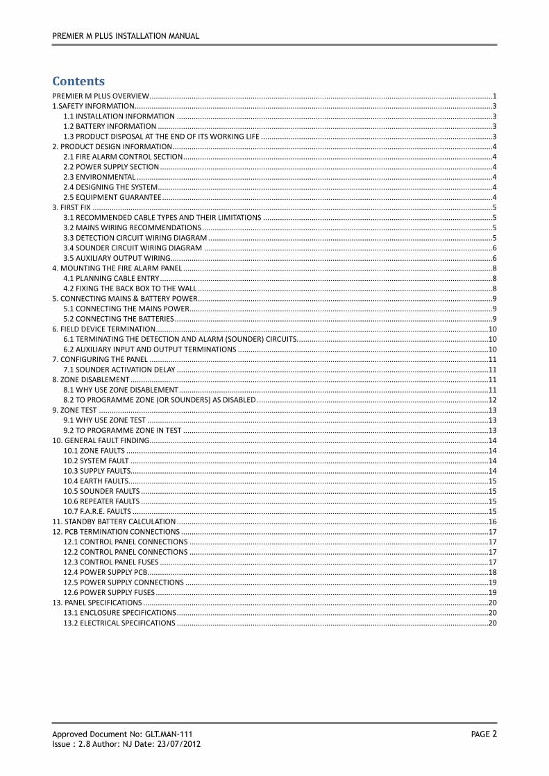
Contents PREMIER M PLUS OVERVIEW ...................................................................................................................................................................1 1.SAFETY INFORMATION ..........................................................................................................................................................................3
1.1 INSTALLATION INFORMATION ......................................................................................................................................................3 1.2 BATTERY INFORMATION ...............................................................................................................................................................3 1.3 PRODUCT DISPOSAL AT THE END OF ITS WORKING LIFE ..............................................................................................................3
2. PRODUCT DESIGN INFORMATION ........................................................................................................................................................4 2.1 FIRE ALARM CONTROL SECTION ...................................................................................................................................................4 2.2 POWER SUPPLY SECTION ..............................................................................................................................................................4 2.3 ENVIRONMENTAL .........................................................................................................................................................................4 2.4 DESIGNING THE SYSTEM ...............................................................................................................................................................4 2.5 EQUIPMENT GUARANTEE .............................................................................................................................................................4
3. FIRST FIX ..............................................................................................................................................................................................5 3.1 RECOMMENDED CABLE TYPES AND THEIR LIMITATIONS .............................................................................................................5 3.2 MAINS WIRING RECOMMENDATIONS ..........................................................................................................................................5 3.3 DETECTION CIRCUIT WIRING DIAGRAM .......................................................................................................................................5 3.4 SOUNDER CIRCUIT WIRING DIAGRAM .........................................................................................................................................6 3.5 AUXILIARY OUTPUT WIRING.........................................................................................................................................................6
4. MOUNTING THE FIRE ALARM PANEL ...................................................................................................................................................8 4.1 PLANNING CABLE ENTRY ..............................................................................................................................................................8 4.2 FIXING THE BACK BOX TO THE WALL ............................................................................................................................................8
5. CONNECTING MAINS & BATTERY POWER ............................................................................................................................................9 5.1 CONNECTING THE MAINS POWER ................................................................................................................................................9 5.2 CONNECTING THE BATTERIES .......................................................................................................................................................9
6. FIELD DEVICE TERMINATION ..............................................................................................................................................................10 6.1 TERMINATING THE DETECTION AND ALARM (SOUNDER) CIRCUITS. ..........................................................................................10 6.2 AUXILIARY INPUT AND OUTPUT TERMINATIONS .......................................................................................................................10
7. CONFIGURING THE PANEL .................................................................................................................................................................11 7.1 SOUNDER ACTIVATION DELAY ....................................................................................................................................................11
8. ZONE DISABLEMENT ..........................................................................................................................................................................11 8.1 WHY USE ZONE DISABLEMENT ...................................................................................................................................................11 8.2 TO PROGRAMME ZONE (OR SOUNDERS) AS DISABLED ..............................................................................................................12
9. ZONE TEST .........................................................................................................................................................................................13 9.1 WHY USE ZONE TEST ..................................................................................................................................................................13 9.2 TO PROGRAMME ZONE IN TEST .................................................................................................................................................13
10. GENERAL FAULT FINDING .................................................................................................................................................................14 10.1 ZONE FAULTS ............................................................................................................................................................................14 10.2 SYSTEM FAULT ..........................................................................................................................................................................14 10.3 SUPPLY FAULTS..........................................................................................................................................................................14 10.4 EARTH FAULTS...........................................................................................................................................................................15 10.5 SOUNDER FAULTS .....................................................................................................................................................................15 10.6 REPEATER FAULTS .....................................................................................................................................................................15 10.7 F.A.R.E. FAULTS .........................................................................................................................................................................15
11. STANDBY BATTERY CALCULATION ....................................................................................................................................................16 12. PCB TERMINATION CONNECTIONS .................................................................................................................................................. 17
12.1 CONTROL PANEL CONNECTIONS .............................................................................................................................................. 17 12.2 CONTROL PANEL CONNECTIONS .............................................................................................................................................. 17 12.3 CONTROL PANEL FUSES ............................................................................................................................................................ 17 12.4 POWER SUPPLY PCB ..................................................................................................................................................................18 12.5 POWER SUPPLY CONNECTIONS ................................................................................................................................................19 12.6 POWER SUPPLY FUSES ..............................................................................................................................................................19
13. PANEL SPECIFICATIONS ....................................................................................................................................................................20 13.1 ENCLOSURE SPECIFICATIONS ....................................................................................................................................................20 13.2 ELECTRICAL SPECIFICATIONS ....................................................................................................................................................20
PREMIER M PLUS INSTALLATION MANUAL
Approved Document No: GLT.MAN-111 PAGE 3
Issue : 2.8 Author: NJ Date: 23/07/2012
1.SAFETY INFORMATION WARNING: Read this section completely before commencing installation.
1.1 INSTALLATION INFORMATION
THIS FIRE ALARM CONTROL PANEL IS CLASS 1 EQUIPMENT AND MUST BE EARTHED
This equipment must be installed and maintained by a qualified and technically experienced person.
This C.I.E. must be wired to a fused spur rated at 3A. It must NOT be connected via a removable plug, or be connected through an RCD device.
Prior to commencing installation of the control panel, ensure that adequate precautions are taken to prevent damage to the sensitive electronic components on the display board and the control board due to electrostatic discharge. You should discharge any static electricity you may have accumulated by touching a convenient earthed object such as an unpainted copper radiator pipe. You should repeat the process at regular intervals during the installation process, especially if you are required to walk over carpets.
The panel must be located in a clean, dry position, which is not subject to excessive shock or vibration and at least 2 metres away from pager systems or any other radio transmitting equipment. The operating temperature range is 0ºC to 40ºC; maximum humidity is 95%.
HANDLING THE PCBS
If the PCBs are to be removed to ease fitting the enclosure and cables, care must be taken to avoid damage by static.
The best method is to wear an earth strap, but touching any earth point (e.g. building plumbing) will help to discharge any static. Always handle PCBs by their sides and avoid touching the legs of any components. Keep the PCBs away from damp dirty areas, e.g. in a small cardboard box.
1.2 BATTERY INFORMATION
This C.I.E. uses 2 x 12V VRLA (Valve Regulated Lead Acid) batteries up to 17 Ah. (also known as SLA or Sealed Lead Acid Batteries)
CAUTION:
RISK OF EXPLOSION IF BATTERY IS REPLACED BY AN INCORRECT TYPE.
DISPOSE OF USED BATTERIES ACCORDING TO BATTERY MANUFACTURERS INSTRUCTIONS
IMPORTANT NOTES ON BATTERIES:
DANGER: Batteries are electrically live at all times. NEVER short circuit the battery terminals.
WARNING: Batteries are often heavy; take great care when lifting and transporting batteries. For weights above 24 kilos, lifting aids should be used.
DANGER: Do NOT attempt to remove the battery lid or tamper with the internal workings of the battery. Electrolyte is a highly corrosive substance, and presents significant danger to yourself and to anything else it touches. In case of accidental skin or eye contact, flush the affected area with plenty of clean, fresh water and seek immediate medical attention.
Valve Regulated Lead Acid (VRLA) batteries are 'low maintenance', requiring no electrolyte top-up or measurement of specific gravity.
1.3 PRODUCT DISPOSAL AT THE END OF ITS WORKING LIFE
Like all electronic equipment, at the end of its working life this unit should not be disposed of in a refuse bin. It should be taken to a local reprocessing site as per the guidelines of the WEEE directive, for correct disposal.
PREMIER M PLUS INSTALLATION MANUAL
Approved Document No: GLT.MAN-111 PAGE 4
Issue : 2.8 Author: NJ Date: 23/07/2012
2. PRODUCT DESIGN INFORMATION
2.1 FIRE ALARM CONTROL SECTION
The Premier M Plus Fire Alarm Control and Indicating Equipment (CIE) Has been designed to EN54-2:1998 A1 + A2 - Fire Detection & Fire Alarm Systems – Control & Indicating Equipment.
As well as meeting the requirements of EN54-2:1998 A1 + A2, the Premier M Plus also has the following options with requirements:-
Clause 7.8 Output to fire alarm devices
Clause 7.9.1 Output to Fire Alarm Routing Equipment
Clause 7.11 Delays to outputs
Clause 10 Test Condition
The Premier M Plus also has the following ancillary functions not required by the Standard:-
Serial repeater output (RS485)
2.2 POWER SUPPLY SECTION
The Premier M Plus Fire Alarm Panels Power Supply Equipment (PSE) has been designed to EN54-4:1998 A1 + A2 - Fire Detection & Fire Alarm Systems – Power Supply Equipment.
The PSE has been designed to charge batteries up to 17 AH within the time limits specified by EN54-4.
The PSE will draw a maximum of 25mA from the battery in the event of mains failure.
The PSE is a switching power supply, with a supply rating (IMAX) of 5.0 Amps
The PSE has a 920mA limited charger output
2.3 ENVIRONMENTAL
It will operate in ambient temperatures of –5 to 40oC
It will operate in a relative humidity of up to 95% (non condensing)
It will withstand vibrations between 5 & 150 Hz
The CIE & PSE should be maintained as described in section 3 of the User Manual, Maintenance Guide & Log Book.
2.4 DESIGNING THE SYSTEM
This manual is not designed to teach Fire Alarm System design. It is assumed that the installer has an understanding of Fire Alarm System components and their use.
We strongly recommend consultation with a suitably qualified, competent person regarding the design of the Fire Alarm System. The System must be commissioned and serviced in accordance with our instructions and the relevant National Standards. Contact the Fire Officer concerned with the property at an early stage in case he has any special requirements.
If in doubt, read BS 5839: Pt 1: 2002 “Fire Detection and Alarm Systems for buildings (Code of Practice for System Design, Installation and Servicing)” available from the BSI, or at your local reference library.
2.5 EQUIPMENT GUARANTEE
If this equipment is not fitted and commissioned according to our guidelines, and the relevant National Standards, by an approved and competent person or organisation, the warranty may become void.
PREMIER M PLUS INSTALLATION MANUAL
Approved Document No: GLT.MAN-111 PAGE 5
Issue : 2.8 Author: NJ Date: 23/07/2012
3. FIRST FIX
All wiring must be installed to meet BS5839-1:2002+A2:2008 and BS 7671 (Wiring Regs) standards. Other National standards of fire alarm system installation should be adhered to where applicable.
3.1 RECOMMENDED CABLE TYPES AND THEIR LIMITATIONS
Screened cables should be used throughout the installation to help shield the Panel from outside interference and ensure EMC compatibility.
The two categories of cable according to BS5839-1:2002+A2:2008, Clause 26 “Fire Detection and Alarm Systems for Buildings (Code of Practice for System Design, Installation and Servicing)” are:
Standard fire resisting cable – to PH30 classification of EN 50200 Enhanced fire resisting cable – to PH120 classification of EN 50200
(Note that all cables should be at least 1mm2 cross section)
On the Premier M Plus Panel the general recommendation would be to use standard fire resistant cable, such as Zeta Alarm Systems Fire Defence cable, Firetuff™ , FP200™ or any equivalent. These cables are screened, and will provide good EMC shielding when properly grounded at the panel. Certain system specifications may demand the use of a particular type of cable and due regard should be paid to this fact. For non-BS5839 installations, other cable types may be suitable.
Depending on the environment, the cables may need mechanical protection (such as a conduit).
3.2 MAINS WIRING RECOMMENDATIONS
The Mains supply to the FACP is fixed wiring, using Fire resisting 3-core cable (Between 1 mm² and 2.5mm²) or a suitable 3-conductor system, fed from an isolating double pole switch fused spur, fused at 5A. IT SHOULD NOT BE CONNECTED THROUGH AN RCD. This should be secure from unauthorised operation and be marked ‘FIRE ALARM: DO NOT SWITCH OFF’. The supply must be exclusive to the Fire Panel. MAKE SURE ANY SPARE ENTRY HOLES ARE COVERED WITH THE GROMMETS PROVIDED.
For information on how to connect Mains to the Panel’s Power Supply PCB, see page 10.
Also refer to rating information on the mains cover inside the FACP.
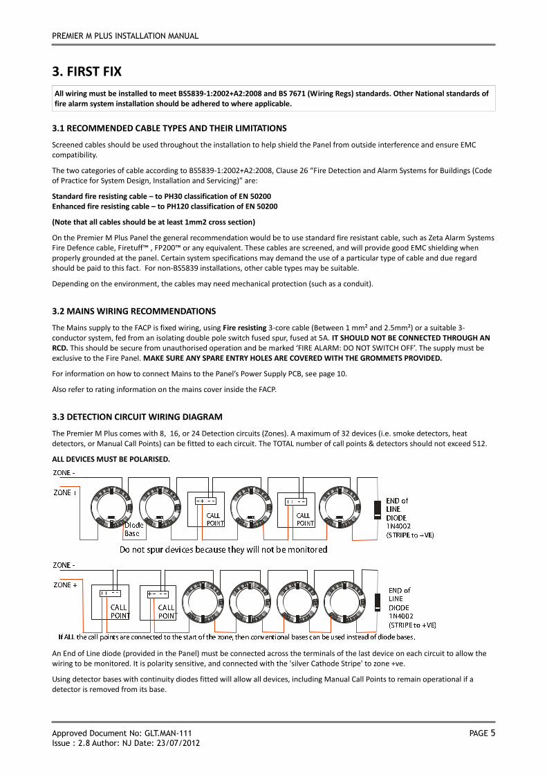
3.3 DETECTION CIRCUIT WIRING DIAGRAM
The Premier M Plus comes with 8, 16, or 24 Detection circuits (Zones). A maximum of 32 devices (i.e. smoke detectors, heat detectors, or Manual Call Points) can be fitted to each circuit. The TOTAL number of call points & detectors should not exceed 512.
ALL DEVICES MUST BE POLARISED.
An End of Line diode (provided in the Panel) must be connected across the terminals of the last device on each circuit to allow the wiring to be monitored. It is polarity sensitive, and connected with the 'silver Cathode Stripe' to zone +ve.
Using detector bases with continuity diodes fitted will allow all devices, including Manual Call Points to remain operational if a detector is removed from its base.
PREMIER M PLUS INSTALLATION MANUAL
Approved Document No: GLT.MAN-111 PAGE 6
Issue : 2.8 Author: NJ Date: 23/07/2012
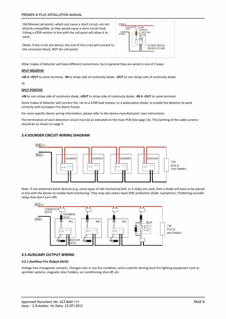
Old Manual call points, which just cause a short circuit, are not directly compatible, as they would cause a short circuit fault. Fitting a 470R resistor in line with the call point will allow it to work. (Note: if this is the last device, the end of line (+ve) will connect to the connector block, NOT the call point)
Other makes of detector will have different connections, but in general they are wired in one of 2 ways:
SPLIT NEGATIVE
+IN & +OUT to same terminal, -IN to stripe side of continuity diode, -OUT to non-stripe side of continuity diode.
Or
SPLIT POSITIVE
+IN to non-stripe side of continuity diode, +OUT to stripe side of continuity diode, -IN & -OUT to same terminal.
Some makes of detector will connect the +ve to a 470R load resistor, or a polarisation diode, to enable the detector to work correctly with European Fire Alarm Panels.
For more specific device wiring information, please refer to the device manufacturers' own instructions.
The termination of each detection circuit must be as indicated on the main PCB (See page 15). The Earthing of the cable screens should be as shown on page 9.
3.4 SOUNDER CIRCUIT WIRING DIAGRAM
Note: If non-polarised alarm devices (e.g. some types of old mechanical bell, or a relay) are used, then a diode will have to be placed in line with the device to enable fault monitoring. They may also need a back EMF protection diode. (symptoms: Chattering sounder relays that don’t turn off).
3.5 AUXILIARY OUTPUT WIRING
3.5.1 Auxiliary Fire Output (AUX):
Voltage free changeover contacts. Changes over in any fire condition, and is used for driving local fire fighting equipment such as sprinkler systems, magnetic door holders, air conditioning shut off, etc.
PREMIER M PLUS INSTALLATION MANUAL
Approved Document No: GLT.MAN-111 PAGE 7
Issue : 2.8 Author: NJ Date: 23/07/2012
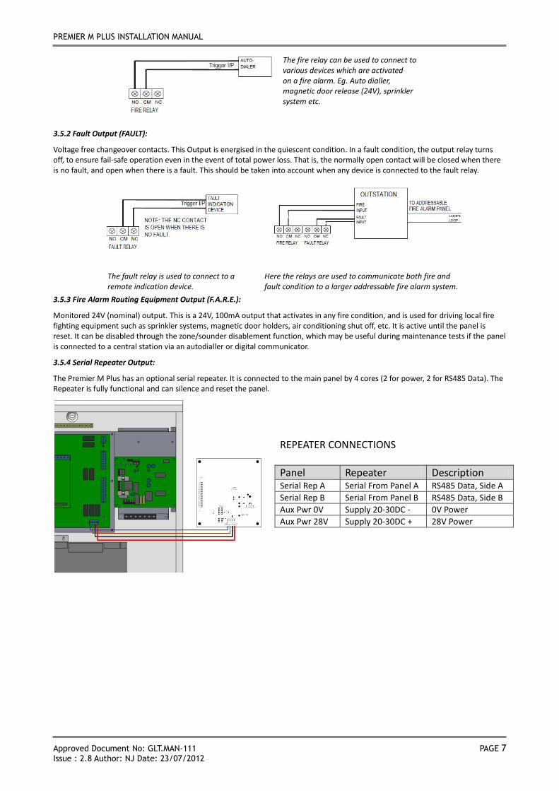
The fire relay can be used to connect to various devices which are activated on a fire alarm. Eg. Auto dialler, magnetic door release (24V), sprinkler system etc.
3.5.2 Fault Output (FAULT):
Voltage free changeover contacts. This Output is energised in the quiescent condition. In a fault condition, the output relay turns off, to ensure fail-safe operation even in the event of total power loss. That is, the normally open contact will be closed when there is no fault, and open when there is a fault. This should be taken into account when any device is connected to the fault relay.
The fault relay is used to connect to a remote indication device.
Here the relays are used to communicate both fire and fault condition to a larger addressable fire alarm system.
3.5.3 Fire Alarm Routing Equipment Output (F.A.R.E.):
Monitored 24V (nominal) output. This is a 24V, 100mA output that activates in any fire condition, and is used for driving local fire fighting equipment such as sprinkler systems, magnetic door holders, air conditioning shut off, etc. It is active until the panel is reset. It can be disabled through the zone/sounder disablement function, which may be useful during maintenance tests if the panel is connected to a central station via an autodialler or digital communicator.
3.5.4 Serial Repeater Output:
The Premier M Plus has an optional serial repeater. It is connected to the main panel by 4 cores (2 for power, 2 for RS485 Data). The Repeater is fully functional and can silence and reset the panel.
REPEATER CONNECTIONS
Panel Repeater Description Serial Rep A Serial From Panel A RS485 Data, Side A
Serial Rep B Serial From Panel B RS485 Data, Side B
Aux Pwr 0V Supply 20-30DC - 0V Power
Aux Pwr 28V Supply 20-30DC + 28V Power
PREMIER M PLUS INSTALLATION MANUAL
Approved Document No: GLT.MAN-111 PAGE 8
Issue : 2.8 Author: NJ Date: 23/07/2012
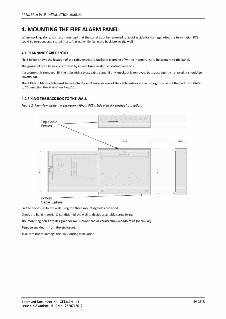
4. MOUNTING THE FIRE ALARM PANEL When working alone, it is recommended that the panel door be removed to avoid accidental damage. Also, the termination PCB could be removed and stored in a safe place while fixing the back box to the wall.
4.1 PLANNING CABLE ENTRY
Fig.2 below shows the location of the cable entries to facilitate planning of wiring (home runs) to be brought to the panel.
The grommets can be easily removed by a push from inside the control panel box.
If a grommet is removed, fill the hole with a brass cable gland. If any knockout is removed, but subsequently not used, it should be covered up.
The 230Va.c. Mains cable must be fed into the enclosure via one of the cable entries at the top right corner of the back box. (Refer to “Connecting the Mains” on Page 10).
4.2 FIXING THE BACK BOX TO THE WALL
Figure 2: Plan view inside the enclosure without PCBs. Side view for surface installation.
Fix the enclosure to the wall using the three mounting holes provided.
Check the build material & condition of the wall to decide a suitable screw fixing.
The mounting holes are designed for No 8 roundhead or countersunk woodscrews (or similar).
Remove any debris from the enclosure.
Take care not to damage the FACP during installation.
PREMIER M PLUS INSTALLATION MANUAL
Approved Document No: GLT.MAN-111 PAGE 9
Issue : 2.8 Author: NJ Date: 23/07/2012
5. CONNECTING MAINS & BATTERY POWER
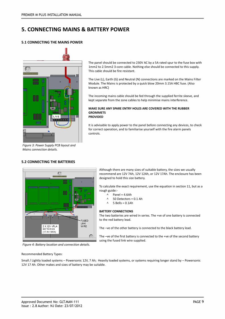
5.1 CONNECTING THE MAINS POWER
Figure 3: Power Supply PCB layout and Mains connection details.
The panel should be connected to 230V AC by a 5A rated spur to the fuse box with 1mm2 to 2.5mm2 3-core cable. Nothing else should be connected to this supply. This cable should be fire resistant. The Live (L), Earth (G) and Neutral (N) connections are marked on the Mains Filter Module. The Mains is protected by a quick blow 20mm 3.15A HBC fuse. (Also known as HRC) The incoming mains cable should be fed through the supplied ferrite sleeve, and kept separate from the zone cables to help minimise mains interference. MAKE SURE ANY SPARE ENTRY HOLES ARE COVERED WITH THE RUBBER GROMMETS PROVIDED It is advisable to apply power to the panel before connecting any devices, to check for correct operation, and to familiarise yourself with the fire alarm panels controls.
5.2 CONNECTING THE BATTERIES
Figure 4: Battery location and connection details.
Although there are many sizes of suitable battery, the sizes we usually recommend are 12V 7Ah, 12V 12Ah, or 12V 17Ah. The enclosure has been designed to hold this size battery. To calculate the exact requirement, use the equation in section 11, but as a rough guide:-
Panel = 4.6Ah 50 Detectors = 0.1 Ah 5 Bells = 0.1Ah
BATTERY CONNECTIONS The two batteries are wired in series. The +ve of one battery is connected to the red battery lead. The –ve of the other battery is connected to the black battery lead. The –ve of the first battery is connected to the +ve of the second battery using the fused link wire supplied.
Recommended Battery Types:
Small / Lightly loaded systems – Powersonic 12V, 7 Ah; Heavily loaded systems, or systems requiring longer stand by – Powersonic 12V 17 Ah. Other makes and sizes of battery may be suitable.
PREMIER M PLUS INSTALLATION MANUAL
Approved Document No: GLT.MAN-111 PAGE 10
Issue : 2.8 Author: NJ Date: 23/07/2012
6. FIELD DEVICE TERMINATION
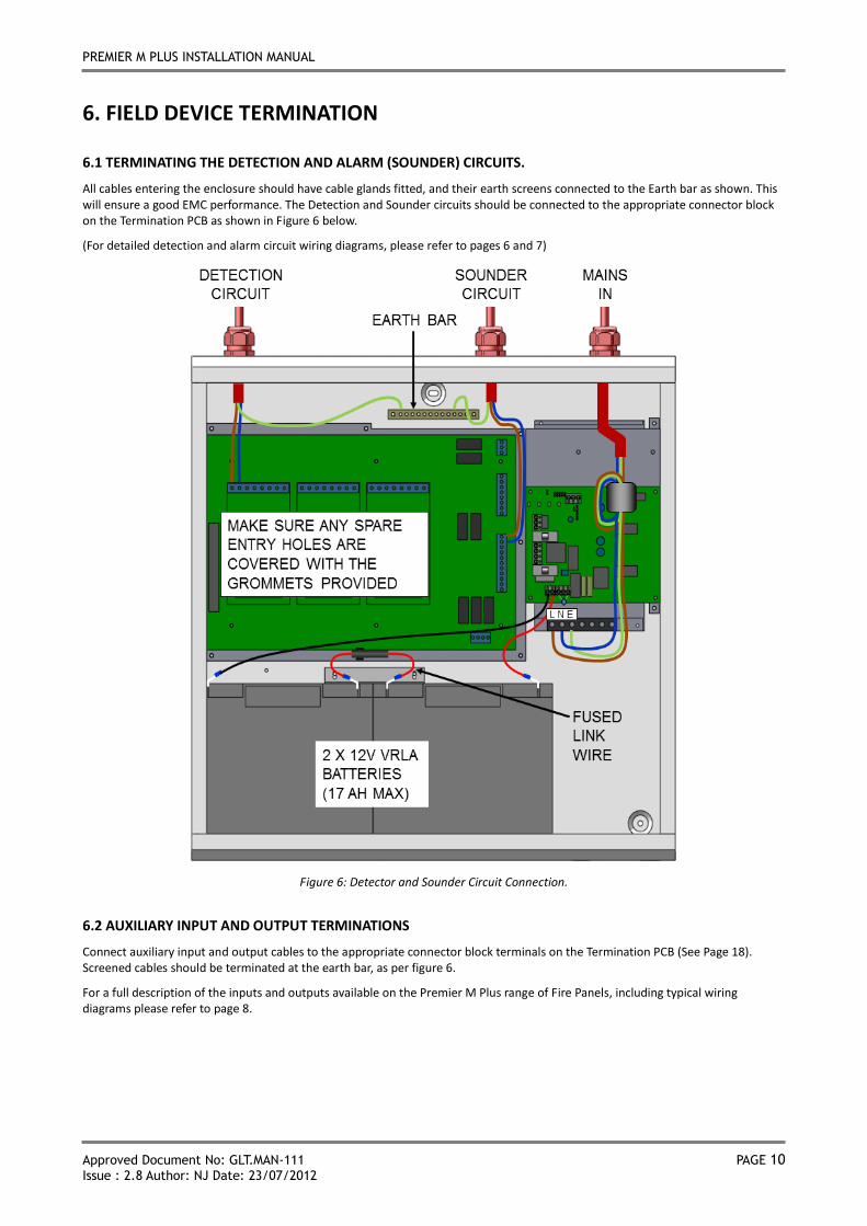
6.1 TERMINATING THE DETECTION AND ALARM (SOUNDER) CIRCUITS.
All cables entering the enclosure should have cable glands fitted, and their earth screens connected to the Earth bar as shown. This will ensure a good EMC performance. The Detection and Sounder circuits should be connected to the appropriate connector block on the Termination PCB as shown in Figure 6 below.
(For detailed detection and alarm circuit wiring diagrams, please refer to pages 6 and 7)
Figure 6: Detector and Sounder Circuit Connection.
6.2 AUXILIARY INPUT AND OUTPUT TERMINATIONS
Connect auxiliary input and output cables to the appropriate connector block terminals on the Termination PCB (See Page 18). Screened cables should be terminated at the earth bar, as per figure 6.
For a full description of the inputs and outputs available on the Premier M Plus range of Fire Panels, including typical wiring diagrams please refer to page 8.
PREMIER M PLUS INSTALLATION MANUAL
Approved Document No: GLT.MAN-111 PAGE 11
Issue : 2.8 Author: NJ Date: 23/07/2012
7. CONFIGURING THE PANEL
7.1 SOUNDER ACTIVATION DELAY
7.1.1 Deciding to use a Delay
A delay of up to nine minutes from the Fire Alarm Panel being triggered, to its Alarm sounder outputs being activated, can be programmed into the panel by the Engineer. This is a particularly useful feature for schools, nightclubs and other public places where the nuisance and panic caused by a false alarm must be avoided. It should be noted that the delay period will apply to ALL zones, except ZONES 1 and 2.
NB A delay following the operation of a manual call point should only occur in exceptional circumstances. For this reason, if a sounder delay needs to be configured, it is highly recommended that all MANUAL CALL POINTS are located in ZONE 1 or ZONE 2, since any programmed delay is not applicable to these zones.
When an Alarm occurs on any zone, it is processed as normal. However, the activation of the sounders is postponed (except in zones 1 and 2) until the delay period has expired, thus allowing the cause of the Alarm to be investigated by the User. If the alarm is false the alarm can be cancelled.
7.1.2 To set a Delay
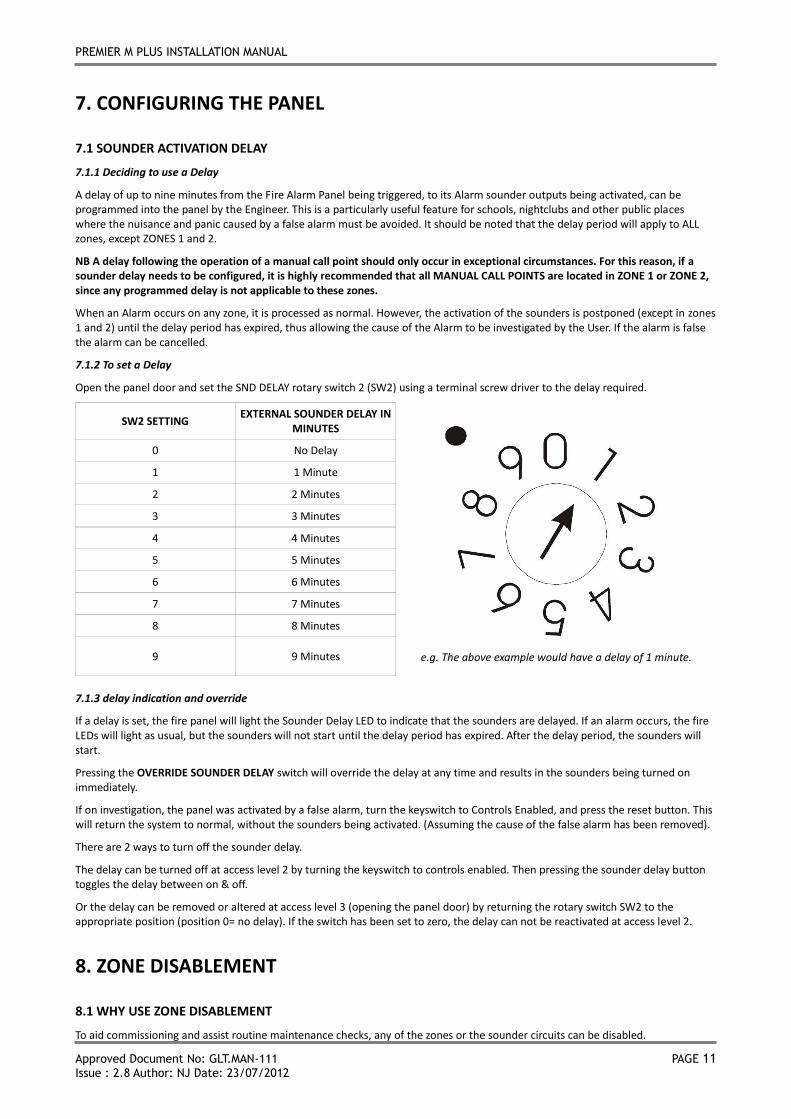
Open the panel door and set the SND DELAY rotary switch 2 (SW2) using a terminal screw driver to the delay required.
SW2 SETTING EXTERNAL SOUNDER DELAY IN
MINUTES
e.g. The above example would have a delay of 1 minute.
0 No Delay
1 1 Minute
2 2 Minutes
3 3 Minutes
4 4 Minutes
5 5 Minutes
6 6 Minutes
7 7 Minutes
8 8 Minutes
9 9 Minutes
7.1.3 delay indication and override
If a delay is set, the fire panel will light the Sounder Delay LED to indicate that the sounders are delayed. If an alarm occurs, the fire LEDs will light as usual, but the sounders will not start until the delay period has expired. After the delay period, the sounders will start.
Pressing the OVERRIDE SOUNDER DELAY switch will override the delay at any time and results in the sounders being turned on immediately.
If on investigation, the panel was activated by a false alarm, turn the keyswitch to Controls Enabled, and press the reset button. This will return the system to normal, without the sounders being activated. (Assuming the cause of the false alarm has been removed).
There are 2 ways to turn off the sounder delay.
The delay can be turned off at access level 2 by turning the keyswitch to controls enabled. Then pressing the sounder delay button toggles the delay between on & off.
Or the delay can be removed or altered at access level 3 (opening the panel door) by returning the rotary switch SW2 to the appropriate position (position 0= no delay). If the switch has been set to zero, the delay can not be reactivated at access level 2.
8. ZONE DISABLEMENT
8.1 WHY USE ZONE DISABLEMENT
To aid commissioning and assist routine maintenance checks, any of the zones or the sounder circuits can be disabled.
PREMIER M PLUS INSTALLATION MANUAL
Approved Document No: GLT.MAN-111 PAGE 12
Issue : 2.8 Author: NJ Date: 23/07/2012
When a zone (or sounder circuit) is disabled, the panel will not respond to any fault or fire signals it receives from that zone. This might be used if the system requires routine maintenance, and the customer needs the system to continue running, but doesn’t want spurious false alarms.
The panel will respond in the usual manner to any events in any non-disabled zones.
8.2 TO PROGRAMME ZONE (OR SOUNDERS) AS DISABLED
Any number of zones (or the sounders) can be disabled, but it is good practice to only disable one zone at a time.
1. Insert and turn control key to enabled position;
2. Press Function button and the GENERAL DISABLEMENT LED will come on (flashing fast);
3. Press Scroll switch and the GENERAL DISABLEMENT LED will flash with a 3 quick flashes then off pattern. Zone 1 fault and zone 1 Test/Disablement LEDs will also flash with the same pattern. The panel is now in SELECT DISABLEMENT MODE.
4. Press select to disable Zone 1, or scroll to the item to disable. The panel will scroll through zones 1-24, then common sounders, then F.A.R.E. Continue to press scroll until the desired Zone or sounder is flashing.
5. When an item has been disabled, the GENERAL DISABLEMENT LED will be lit. The item that has been disabled will now flash 3 quick flashes then on. (This means that it has been disabled, but is still the focus of the disablement select/de-select operation.) If scroll is pressed once more, the disabled part’s LED will now be lit steady, and the next item will flash 3 quick flashes then off.
6. If more than one zone needs to be disabled, press scroll again until the required zone is selected.
7. If the panel needs to be taken out of SELECT DISABLEMENT MODE (e.g. to silence a fault on another part of the system), turn the keyswitch off, then back on again.
8. To enable the zones again. If the panel is still in SELECT DISABLEMENT MODE, jump to paragraph 9, otherwise, turn the keyswitch to controls enabled, press FUNCTION button followed by scroll button. Zone 1 will then flash with a 3 quick flashes pattern. The panel is now back in SELECT DISABLEMENT MODE
9. Press the scroll button until the disabled zone or sounder has been selected. Press function button. Scroll to any other disabled zone and enable in the same way. When all zones are enabled again, the GENERAL DISABLEMENT LED will flash 3 quick flashes then off. Turn the keyswitch to off to return the system to normal.
NOTE: The disablement function is only intended for a short term use, while maintenance work or repairs are carried out. The panel should not be left in a disabled state permanently. Remember that the disabled section will not report a fire, so extra care should be paid in that area of the building.
PREMIER M PLUS INSTALLATION MANUAL
Approved Document No: GLT.MAN-111 PAGE 13
Issue : 2.8 Author: NJ Date: 23/07/2012
9. ZONE TEST
9.1 WHY USE ZONE TEST
To aid commissioning and assist routine maintenance checks, a non-latching test mode facility is available.
When a detector or manual call point is triggered on any zone in Test, the Alarm sounders operate for approximately four seconds on and four seconds off. This cycle continues until the cause of the Alarm is removed (either by the test smoke clearing from the detector or the manual call point being reset), at which point, the detector circuit also automatically resets.
Should an Alarm occur on a zone that is not programmed as test mode, the Alarm will be processed in the normal way. The testing of the zone in test will temporarily be suspended until the Alarm(s) from the other zones are investigated and then reset. At this point, zone retesting may resume.
9.2 TO PROGRAMME ZONE IN TEST
NOTE: Only one zone can be programmed in test at any one time.
1. Insert and turn control key to enabled position;
2. Press FUNCTION button twice. The General Zone test LED is now on (flashing fast);
3. Press “Sounder Delay”, ”Silence Buzzer”, ”Silence Buzzer”, “Sounder Delay”. The General Zone Test LED will now flash 3 quick flashes then off.
4. Press scroll button and Zone one fault & test LEDs will flash in synchronisation with the General Zone test;
5. Press scroll button to the desired Zone for test. Once the desired Zone LED is flashing, press select. The LEDs will now flash on and off. This Zone is now in test mode.
6. Once testing of that zone is completed, press select to exit test mode for that zone. The LEDs will now flash 3 quick flashes then off.
7. Press scroll button to move to another Zone to test, or turn the control key switch to off position to exit test mode.
Notes:
The panel will not allow a zone to be programmed to test mode if it is disabled.
While in test mode, the panel is in Access level 2. Steps should be taken to ensure there is no unauthorised access to panel controls during test mode.
PREMIER M PLUS INSTALLATION MANUAL
Approved Document No: GLT.MAN-111 PAGE 14
Issue : 2.8 Author: NJ Date: 23/07/2012
10. GENERAL FAULT FINDING
10.1 ZONE FAULTS
The Zone Faults are non-latching faults. That is, if the fault has been cleared, the panel will automatically reset itself.
Open circuit faults will be indicated by zone(s) fault LED being lit steady, the internal Fault Buzzer will sound and the General Fault LED will be lit.
Short circuit faults will be indicated by zone(s) fault LED and the short circuit LED Flashing, the internal Fault Buzzer will sound and the General Fault LED will be lit.
Suggested Action
a) Check that the correct end of line device has been fitted (1N4002 Diode)
b) Check that the End Of line is fitted the correct way (with Cathode Stripe to zone +ve)
c) Disconnect the wiring for the zone showing fault, and refit the end of line diode at that zone terminal in the panel. If the fault condition for that zone clears, this confirms there is a wiring fault.
d) Double-check the wiring and the end of line diode on the zone. Trace the fault with consideration for the type of fault indicated.(HINT: splitting the cable half way down the zone, and fitting the end of line diode to the new end point helps to determine which section of cable is giving the fault)
Note: A possible fault is a detector head badly seated in a base that is not making a good connection.
c) A short circuit on a zone could be caused by the end of line diode being fitted backwards.
d) Check that the detectors are compatible with this FACP. Note that some makes of detector will require a series resistor or diode to be fitted to work properly. There is usually a spare connector on the base to accommodate this (check instructions that came with the detector).
e) Measure the resistance of the zone cabling (Remove from panel and short out end of line). Ideally this should be less than 50 ohms. Above 70 ohms may cause an open circuit fault.
10.2 SYSTEM FAULT
A system fault is an abnormal microprocessor running condition due to various unexpected phenomena.
This will result in the panel attempting to correct itself. Should this fault occur, the System Fault LED, General Fault LED, General Fault relay and fault internal buzzer will be constantly active until the control keyswitch is turned from off position to control enable position. This should cause this fault condition to reset. If not, consult your supplier.
10.3 SUPPLY FAULTS
A power supply fault is indicative of one or more of the following faults: -
1. Loss of Mains power – Remedy
a) Check mains fuse (in fused mains filter). Also, check that mains power is present.
b) Check 24V Supply fuse on PSU board FS1 & FS2.
c) Check 28V supply fuse on Termination Board (FS9)
2. Loss of Battery power – Remedy
a) Check battery fuse in battery link wire.
b) Check that battery connections are secure.
3. Low Battery – Remedy
a) Check battery voltage – replace if necessary.
4. Wrong Charging Voltage.
The charging voltage should be 27.6 V off load at 25oC. (Note that the PSU will turn off the charger voltage when the batteries are disconnected)
5. Battery High internal resistance.
In accordance with EN54-4, the power supply will monitor the batteries internal resistance. It will report a fault if the internal

PREMIER M PLUS INSTALLATION MANUAL
Approved Document No: GLT.MAN-111 PAGE 15
Issue : 2.8 Author: NJ Date: 23/07/2012
resistance is greater than 0.9 ohm. These batteries would then need to be replaced.
10.4 EARTH FAULTS
An EARTH fault indicates that something is shorting to earth (usually through the cable screen). Disconnect the earth screens one at a time to determine the problem line.
(Note: connecting other equipment , e.g. an oscilloscope , to the panel can give an earth fault.)
The voltage between battery –Ve and earth should be 15-16 volts. If it is not, the voltage measured should indicate what is shorting to earth.
Note that the M plus can monitor for earth faults through the motherboard, or through the PSU. They should not both be set to monitor as this could report a fault. The recommended setting it to monitor via the motherboard.
10.5 SOUNDER FAULTS
Check that the correct END of Line resistor has been fitted (10K – brown, black, orange, gold).
Check that all sounder fuses are OK (FS4, FS5,FS7 & FS8 – 400mA QB).
If working on an existing installation, check that the devices are polarised (See Page 5).
Check cable continuity (Remove from panel and measure continuity - should read 10K).
HINT: Disconnecting the sounder wiring & fitting 10K EOL at the panel will confirm whether the panel or the wiring/sounders are the cause of the fault.
10.6 REPEATER FAULTS
Check that the power and RS485 connections between the panel and repeater are correct.
Check The AUX supply fuse in the panel (FS6 – 250mA).
Check the supply fuse in the repeater (FS1 – 500mA).
10.7 F.A.R.E. FAULTS
Check that the correct END of Line resistor has been fitted. (10K – brown, black, orange, gold).
Check there are no open or short circuits on the F.A.R.E. line.
Check that the fuse is OK (FS3 – 100mA QB).
PREMIER M PLUS INSTALLATION MANUAL
Approved Document No: GLT.MAN-111 PAGE 16
Issue : 2.8 Author: NJ Date: 23/07/2012
11. STANDBY BATTERY CALCULATION In order to calculate the standby battery size required, the following formula can be used:-
Battery Size (Standby time in Amp Hours) = 1.25 x [(TALM x IALM) + (TSBY x (IQP + IQZ))]
Where:
TALM = Maximum time in hours required for the alarm [½ hour is most common time]
IALM = Total Alarm Current in amps for all alarm devices connected to the alarm circuits
TSBY = Standby time in hours for the system after mains failure [normally 24, 48 or 72 hr]
IQP = Quiescent current in amps of control panel in fault condition [because of mains failure]
IQZ = Quiescent current in amps of all detection zones. Eg Ion detector 0.00005 Amp (50 μA), Optical Detector = 0.0001 Amp (100 μA)
Typical Example:
A system comprises of 24 zones. Each zone has 20 smoke detectors. 10 bells are connected to each of the common sounder circuit. The required standby is 24 hours. It will need to operate in alarm for ½ hour.
Calculate the battery size required.
TALM = 0.5 Hr
IALM (panel) = 0.205mA
IALM = (4x10) x 0.025 =1.0A [This typical bell current is 25 mA. Most alarm Devices show their operating current on their instruction sheet. Typical sounders will take less current]
TSBY = 24 Hr
IQP = 0.105A
IQZ =24 x 20 x 0.00006 =0.0288A [the quiescent current for a typical optical detector is 60 μA
Therefore using the equation:
Battery Size (Standby time in Amp Hours) = 1.25 x [(TALM x IALM) + (TSBY x (IQP + IQZ))]
Battery Size (Standby time in Amp Hours) = 1.25 x [(0.5 x (0.205+1.0)) + (24 x (0.105 + 0.0288))]
Battery Size (Standby time in Amp Hours) = 1.25 x [(0.5 x 1.205) + (24 x 0.1338)]
Battery Size (Standby time in Amp Hours) = 1.25 x [0.6025 + 3.2112]
Battery Size (Standby time in Amp Hours) = 1.25 x 3.8137
Battery Size (Standby time in Amp Hours) = 4.76 Amp Hours
This system would require a minimum of 4.76Ah batteries, so we would recommend using 7Ah batteries (the nearest convenient size).
*On a system with a heavier load, it may be necessary to use larger batteries. This may require a separate battery box to hold the batteries.
PREMIER M PLUS INSTALLATION MANUAL
Approved Document No: GLT.MAN-111 PAGE 17
Issue : 2.8 Author: NJ Date: 23/07/2012
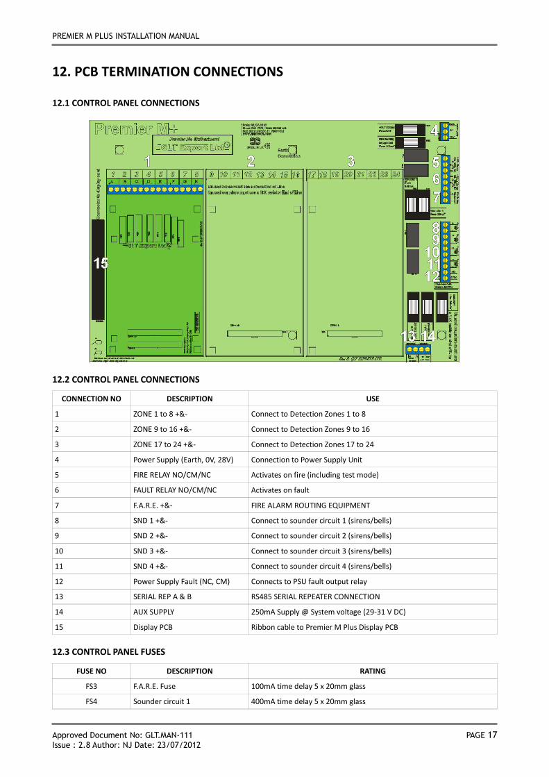
12. PCB TERMINATION CONNECTIONS
12.1 CONTROL PANEL CONNECTIONS
12.2 CONTROL PANEL CONNECTIONS
CONNECTION NO DESCRIPTION USE
1 ZONE 1 to 8 +&- Connect to Detection Zones 1 to 8
2 ZONE 9 to 16 +&- Connect to Detection Zones 9 to 16
3 ZONE 17 to 24 +&- Connect to Detection Zones 17 to 24
4 Power Supply (Earth, 0V, 28V) Connection to Power Supply Unit
5 FIRE RELAY NO/CM/NC Activates on fire (including test mode)
6 FAULT RELAY NO/CM/NC Activates on fault
7 F.A.R.E. +&- FIRE ALARM ROUTING EQUIPMENT
8 SND 1 +&- Connect to sounder circuit 1 (sirens/bells)
9 SND 2 +&- Connect to sounder circuit 2 (sirens/bells)
10 SND 3 +&- Connect to sounder circuit 3 (sirens/bells)
11 SND 4 +&- Connect to sounder circuit 4 (sirens/bells)
12 Power Supply Fault (NC, CM) Connects to PSU fault output relay
13 SERIAL REP A & B RS485 SERIAL REPEATER CONNECTION
14 AUX SUPPLY 250mA Supply @ System voltage (29-31 V DC)
15 Display PCB Ribbon cable to Premier M Plus Display PCB
12.3 CONTROL PANEL FUSES
FUSE NO DESCRIPTION RATING
FS3 F.A.R.E. Fuse 100mA time delay 5 x 20mm glass
FS4 Sounder circuit 1 400mA time delay 5 x 20mm glass
PREMIER M PLUS INSTALLATION MANUAL
Approved Document No: GLT.MAN-111 PAGE 18
Issue : 2.8 Author: NJ Date: 23/07/2012
FS5 Sounder circuit 2 400mA time delay 5 x 20mm glass
FS6 AUX Supply 250mA time delay 5 x 20mm glass
FS7 Sounder circuit 3 400mA time delay 5 x 20mm glass
FS8 Sounder circuit 4 400mA time delay 5 x 20mm glass
FS9 28V Supply Fuse 6A time delay 5 x 20mm glass
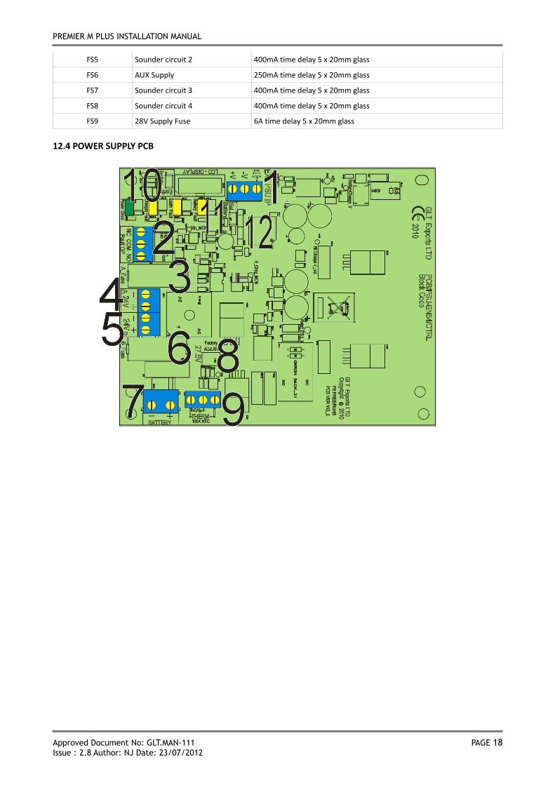
12.4 POWER SUPPLY PCB
PREMIER M PLUS INSTALLATION MANUAL
Approved Document No: GLT.MAN-111 PAGE 19
Issue : 2.8 Author: NJ Date: 23/07/2012
12.5 POWER SUPPLY CONNECTIONS
CONNECTION NO DESCRIPTION USE
1 EXT PSU IP External Power input from Switch Mode cage
2 FAULT OP Volt free fault relay, normally energised
3 A-FUSE Fuse for the first 24V output
4 24V A Connection for the first 24 V output
5 24V B Connection for the second 24 V output
6 B-FUSE Fuse for the second 24V output
7 BATTERY Battery connection. 2 x 12V SLA batteries wired in series
8 FACTORY ADJUST Charger adjust pot. DO NOT ADJUST
9 THERM Battery charger temperature compensation thermistor
10 EARTH ISOLATE Jumper link to enable / disable earth fault reporting
11 SEL. BATTERY Link to put charger in calibration mode from power up.
12 CN2/CN3 ISP programming connector
12.6 POWER SUPPLY FUSES
FUSE NO DESCRIPTION RATING
IN LINK WIRE Battery Fuse 5.0A time delay 5 x 20mm glass
FS1 Supply Fuse A 2.5A time delay 5 x 20mm glass
FS2 Supply Fuse B 2.5A time delay 5 x 20mm glass
PREMIER M PLUS INSTALLATION MANUAL
Approved Document No: GLT.MAN-111 PAGE 20
Issue : 2.8 Author: NJ Date: 23/07/2012
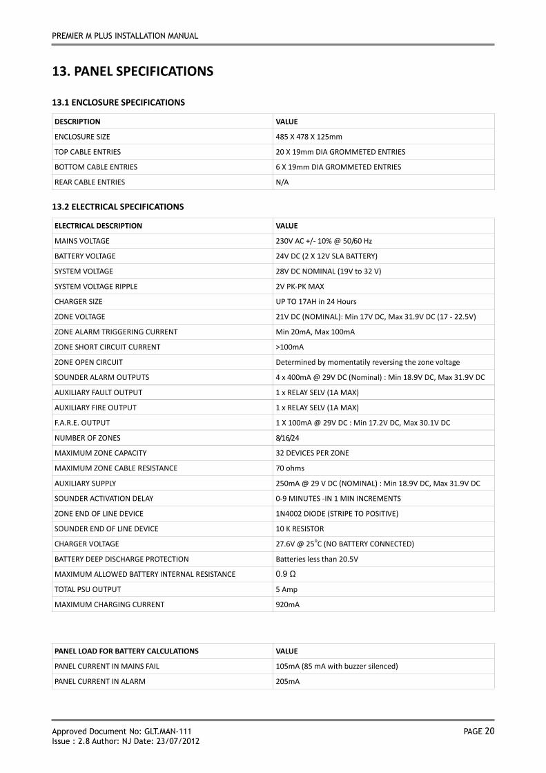
13. PANEL SPECIFICATIONS
13.1 ENCLOSURE SPECIFICATIONS
DESCRIPTION VALUE
ENCLOSURE SIZE 485 X 478 X 125mm
TOP CABLE ENTRIES 20 X 19mm DIA GROMMETED ENTRIES
BOTTOM CABLE ENTRIES 6 X 19mm DIA GROMMETED ENTRIES
REAR CABLE ENTRIES N/A
13.2 ELECTRICAL SPECIFICATIONS
ELECTRICAL DESCRIPTION VALUE
MAINS VOLTAGE 230V AC +/- 10% @ 50/60 Hz
BATTERY VOLTAGE 24V DC (2 X 12V SLA BATTERY)
SYSTEM VOLTAGE 28V DC NOMINAL (19V to 32 V)
SYSTEM VOLTAGE RIPPLE 2V PK-PK MAX
CHARGER SIZE UP TO 17AH in 24 Hours
ZONE VOLTAGE 21V DC (NOMINAL): Min 17V DC, Max 31.9V DC (17 - 22.5V)
ZONE ALARM TRIGGERING CURRENT Min 20mA, Max 100mA
ZONE SHORT CIRCUIT CURRENT >100mA
ZONE OPEN CIRCUIT Determined by momentatily reversing the zone voltage
SOUNDER ALARM OUTPUTS 4 x 400mA @ 29V DC (Nominal) : Min 18.9V DC, Max 31.9V DC
AUXILIARY FAULT OUTPUT 1 x RELAY SELV (1A MAX)
AUXILIARY FIRE OUTPUT 1 x RELAY SELV (1A MAX)
F.A.R.E. OUTPUT 1 X 100mA @ 29V DC : Min 17.2V DC, Max 30.1V DC
NUMBER OF ZONES 8/16/24
MAXIMUM ZONE CAPACITY 32 DEVICES PER ZONE
MAXIMUM ZONE CABLE RESISTANCE 70 ohms
AUXILIARY SUPPLY 250mA @ 29 V DC (NOMINAL) : Min 18.9V DC, Max 31.9V DC
SOUNDER ACTIVATION DELAY 0-9 MINUTES -IN 1 MIN INCREMENTS
ZONE END OF LINE DEVICE 1N4002 DIODE (STRIPE TO POSITIVE)
SOUNDER END OF LINE DEVICE 10 K RESISTOR
CHARGER VOLTAGE 27.6V @ 25oC (NO BATTERY CONNECTED)
BATTERY DEEP DISCHARGE PROTECTION Batteries less than 20.5V
MAXIMUM ALLOWED BATTERY INTERNAL RESISTANCE 0.9 Ω
TOTAL PSU OUTPUT 5 Amp
MAXIMUM CHARGING CURRENT 920mA
PANEL LOAD FOR BATTERY CALCULATIONS VALUE
PANEL CURRENT IN MAINS FAIL 105mA (85 mA with buzzer silenced)
PANEL CURRENT IN ALARM 205mA
PREMIER M PLUS INSTALLATION MANUAL
Approved Document No: GLT.MAN-111 PAGE 21
Issue : 2.8 Author: NJ Date: 23/07/2012
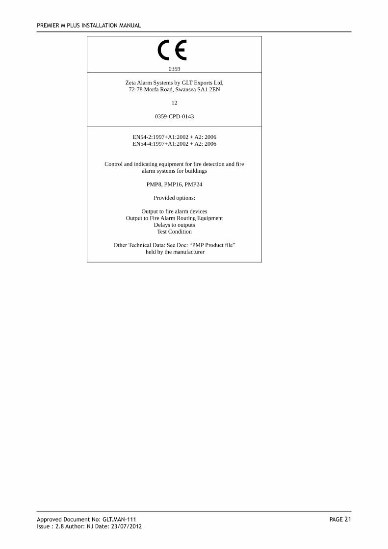
0359
Zeta Alarm Systems by GLT Exports Ltd,
72-78 Morfa Road, Swansea SA1 2EN
12
0359-CPD-0143
EN54-2:1997+A1:2002 + A2: 2006
EN54-4:1997+A1:2002 + A2: 2006
Control and indicating equipment for fire detection and fire
alarm systems for buildings
PMP8, PMP16, PMP24
Provided options:
Output to fire alarm devices
Output to Fire Alarm Routing Equipment
Delays to outputs
Test Condition
Other Technical Data: See Doc: “PMP Product file”
held by the manufacturer