Embed Size (px)
Citation preview

Printed in China for GTO Access Systems, LLC. Copyright© 2016 GTO Access Systems, LLCDocument Number: R56208 REV A (12.19.16)
GTO Sales: 800-543-4283 • Fax 850-575-8912
GTO Technical Service 800-543-1236
For 24 hour/day, 7 day/week Technical Service visit http://support.gtoinc.comFor more information on Mighty Mule’s full line of Automatic Gate Operators and Access Controls visit
www.mightymule.com
MM562
ACCESS SYSTEMS, LLC
Mighty Mule® is the retail brand of GTO Access Systems, LLC3121 Hartsfield Road • Tallahassee, FL 32303
This product meets the requirements of UL325 6th Edition, 2016, the standard for gate operator safety.
Installation Manual
Horizontal Support
Gate Swings Evenly and FreelyHung Firmly and Plumb
Receiver
Post Bracket
Control Box with Battery
Fence Post Set in ConcreteRun 1000' (max.) of lowvoltage wire to controlbox from transformer(wire not included).
Power Cable
PVC conduit (not included)to protect wire from lawnmowers and weed eaters.
PVC conduit (not included)to run second opener powercable under driveway.
Gate Bracket
Warning Sign
First Gate Opener Second Gate OpenerHorizontal Support
Post BracketGate Bracket
120 Volt indoorTransformer
(surge protector not supplied)
Example of finished installation(installations vary slightly on different types of gates)

Product UsageThe Mighty Mule Gate Operator meets all of the safety requirements of a Class I Residential Vehicular Gate Operator and is intended for use solely with vehicular swing gates in single-family residential applications that meet the Class I category listed in the table below.
Residential Vehicular Gate Operator-Class I: A vehicular gate operator (or system) intended for use in garages or parking areas associated with a residence of one-to-four single families.
Commercial/General Access Vehicular Gate Operator-Class II: A vehicular gate operator (or system) intended for use in a commercial location or building such as a multi-family housing unit (five or more single family units), hotel, garages, retail store, or other buildings accessible by or servicing the general public.
Industrial/Limited Access Vehicular Gate Operator–Class III: A vehicular gate operator (or system) intended for use in an industrial location or building such as a factory or loading dock area or other locations not accessible by or intended to service the general public.
Restricted Access Vehicular Gate Operator– Class IV: A vehicular gate operator (or system) intended for use in an industrial location or building such as a factory or loading dock area or other locations not accessible by or intended to service the general public.
Vehicular Gate Operator Class Categories
i
WARNINGThis equipment meets Underwriters Laboratory Standard 325 (UL 325). However, gate equipment has hazards associated with its use and therefore by installing this product the installer and user accept full responsibility for following and noting the installation and safety instructions. Failure to follow installation and safety instructions can result in hazards developing due to improper assembly. You agree to properly install this product and that if you fail to do so GTO Access Systems, LLC, shall in no event be liable for direct, indirect, incidental, special or consequential damages or loss of profits whether based in contract tort or any other legal theory during the course of the warranty or at any time thereafter. The installer and/or user agree to assume responsibility for all liability and use of this product releasing GTO Access Systems, LLC, from any and all liability. If you are not in agreement with this disclaimer or do not feel capable of properly following all installation and safety instructions you may return this product for full replacement value.
READ ALL INSTRUCTIONS CAREFULLY AND COMPLETELY before attempting to install and use this automatic gate operator. This gate operator produces a high level of force. Stay clear of the unit while it is operating and exercise caution at all times.
ALL AUTOMATIC GATE OPERATORS ARE INTENDED FOR USE ON VEHICULAR GATES ONLY.
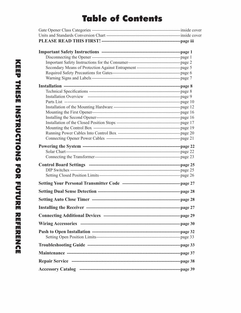
Table of Contents
KEEP
THES
E INSTR
UCTIO
NS FO
R FU
TUR
E REFER
ENCE
Gate Opener Class Categories ------------------------------------------------------------- inside coverUnits and Standards Conversion Chart --------------------------------------------------- inside coverPLEASE READ THIS FIRST! --------------------------------------------------page iii
Important Safety Instructions --------------------------------------------------page 1 Disconnecting the Opener -------------------------------------------------------------page 1 Important Safety Instructions for the Consumer ------------------------------------page 2 Secondary Means of Protection Against Entrapment ------------------------------page 5 Required Safety Precautions for Gates -----------------------------------------------page 6 Warning Signs and Labels -------------------------------------------------------------page 7
Installation --------------------------------------------------------------------------page 8 Technical Specifications ---------------------------------------------------------------page 8 Installation Overview ----------------------------------------------------------------page 9 Parts List -- ------------------------------------------------------------------------------page 10 Installation of the Mounting Hardware ----------------------------------------------page 12 Mounting the First Opener-------------------------------------------------------------page 16 Installing the Second Opener ----------------------------------------------------------page 16 Installation of the Closed Position Stops --------------------------------------------page 17 Mounting the Control Box ------------------------------------------------------------page 19 Running Power Cables Into Control Box -------------------------------------------page 20 Connecting Opener Power Cables ---------------------------------------------------page 21 Powering the System --------------------------------------------------------------page 22 Solar Chart -------------------------------------------------------------------------------page 22 Connecting the Transformer -----------------------------------------------------------page 23
Control Board Settings ----------------------------------------------------------page 25 DIP Switches ----------------------------------------------------------------------------page 25 Setting Closed Position Limits --------------------------------------------------------page 26
Setting Your Personal Transmitter Code ----------------------------------------page 27
Setting Dual Sense Detection ---------------------------------------------------------page 28
Setting Auto Close Timer -------------------------------------------------------------page 28
Installing the Receiver -----------------------------------------------------------------page 27
Connecting Additional Devices -----------------------------------------------------page 29
Wiring Accessories ---------------------------------------------------------------------page 30
Push to Open Installation --------------------------------------------------------page 32 Setting Open Position Limits ----------------------------------------------------------page 33
Troubleshooting Guide -----------------------------------------------------------page 33
Maintenance ------------------------------------------------------------------------page 37
Repair Service ---------------------------------------------------------------------page 38
Accessory Catalog ----------------------------------------------------------------page 39

iii
Please Read This First!
Thank you for purchasing a Mighty Mule Gate Operator—GTO's "do-it-yourself" automatic gate operator! When correctly installed and properly used, your Mighty Mule Gate Operator will give you many years of reliable service. Please read the following information and watch the enclosed video to ensure you have the correct system for your particular needs. Furthermore, this manual and the DVD will enable you to properly install your Mighty Mule Gate Operator.
The Mighty Mule Gate Operator is designed for installation on a pull-to-open single leaf gate (gates that open into the property). By purchasing an accessory bracket, the Mighty Mule Gate Operator can accommodate a push-to-open single leaf gate (gates that open out from the property). The gate must not exceed 18 feet in length or weigh more than 850 pounds (please see Technical Specifications on page 8). The Mighty Mule Gate Operator can be used on vinyl, aluminum, chain link, farm tube, and wrought iron gates. Use on solid surface gates is not recommended. Solid surface gates have a high resistance to the wind. If the wind is strong enough, the operator will obstruct and stop.
The Mighty Mule Gate Operator accommodates extra transmitters, digital keypads, solar panels, push buttons, automatic gate locks, and other access control products. These optional accessories (see the Mighty Mule Accessory Catalog) are available at most stores. Your store should be able to special order any accessory not in stock. If your store cannot special order accessories, please call the Mighty Mule Sales Department (800-543-GATE).
The Mighty Mule Gate Operator features Dual Sense Technology™. This feature makes the gate stop and reverse direction when it comes in contact with an obstruction. This is factory set to the most sensitive setting and must be adjusted during installation.
The Mighty Mule Gate Operator also has an adjustable auto-close feature. After the gate reaches the fully open position, it can be set to remain open up to 120 seconds before automatically closing. Pressing the transmitter button at any time after the gate opens fully will cause it to close immediately. OFF is the factory setting; meaning the gate will stay open until you press the transmitter (or keypad, etc.) again.
NOTE—If your application requires any of the following: • Swing gates longer than 18 feet or weighing
more than 850 pounds • Slide gates • Heavy duty or commercial uses • Professional installation
Go to www.gtoaccess.com for a dealer or retailer near you or call (800) 543-4283 for information about our Linear PRO Access professional line of gate operators and accessories. Our Sales Department will be glad to give you the name and phone number of a Linear PRO Access dealer near you.
BEFORE YOU BEGIN TO INSTALL YOUR AUTOMATIC GATE OPERATOR:watch the enclosed video and read these instructions carefully and completely
to become familiar with all parts and installation steps. The video is only designed as an overview of the installation procedure. You must read the installation manual for detailed
instructions on gate operator safety and proper use of the gate operator.
MM562 Installation Instructions 1
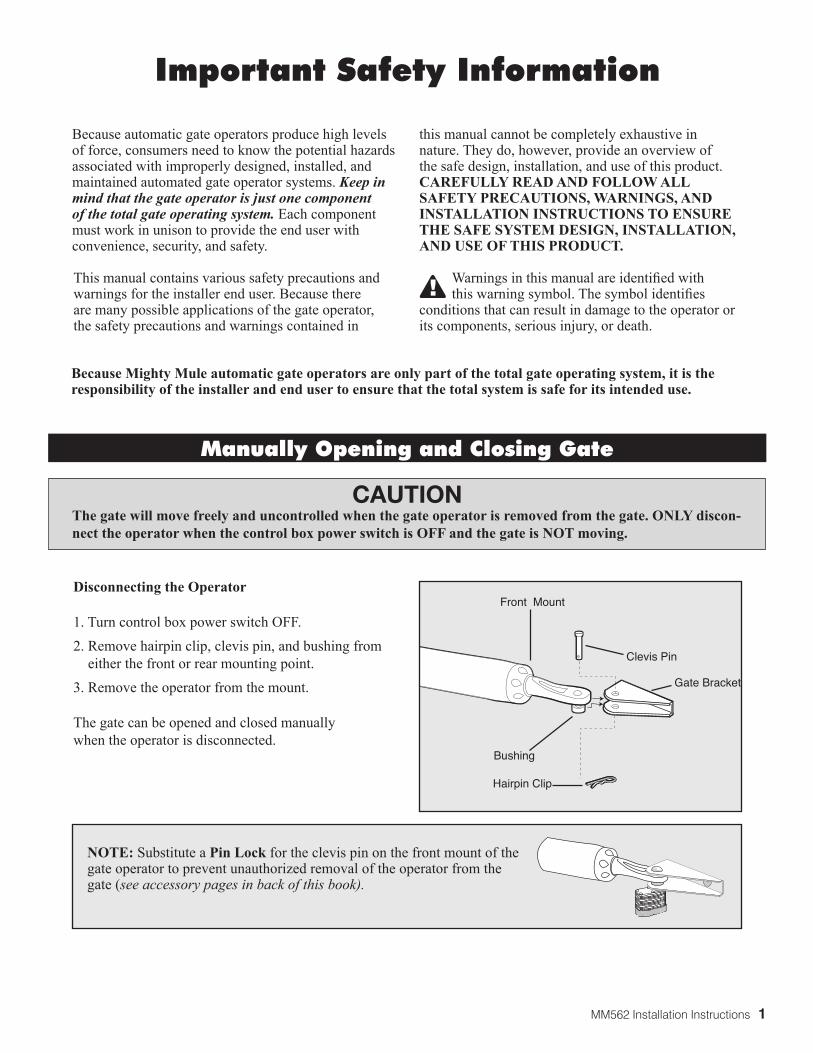
Clevis Pin
Hairpin Clip
Gate Bracket
Front Mount
Bushing
Because automatic gate operators produce high levels of force, consumers need to know the potential hazards associated with improperly designed, installed, and maintained automated gate operator systems. Keep in mind that the gate operator is just one component of the total gate operating system. Each component must work in unison to provide the end user with convenience, security, and safety.
This manual contains various safety precautions and warnings for the installer end user. Because there are many possible applications of the gate operator, the safety precautions and warnings contained in
Disconnecting the Operator 1. Turn control box power switch OFF.2. Remove hairpin clip, clevis pin, and bushing from
either the front or rear mounting point.3. Remove the operator from the mount.
The gate can be opened and closed manuallywhen the operator is disconnected.
this manual cannot be completely exhaustive in nature. They do, however, provide an overview of the safe design, installation, and use of this product. CAREFULLY READ AND FOLLOW ALL SAFETY PRECAUTIONS, WARNINGS, AND INSTALLATION INSTRUCTIONS TO ENSURE THE SAFE SYSTEM DESIGN, INSTALLATION, AND USE OF THIS PRODUCT.
Warnings in this manual are identified with this warning symbol. The symbol identifies
conditions that can result in damage to the operator or its components, serious injury, or death.
Manually Opening and Closing Gate
Because Mighty Mule automatic gate operators are only part of the total gate operating system, it is the responsibility of the installer and end user to ensure that the total system is safe for its intended use.
CAUTIONThe gate will move freely and uncontrolled when the gate operator is removed from the gate. ONLY discon-nect the operator when the control box power switch is OFF and the gate is NOT moving.
NOTE: Substitute a Pin Lock for the clevis pin on the front mount of the gate operator to prevent unauthorized removal of the operator from the gate (see accessory pages in back of this book).
Important Safety Information
2 MM562 Installation Instructions
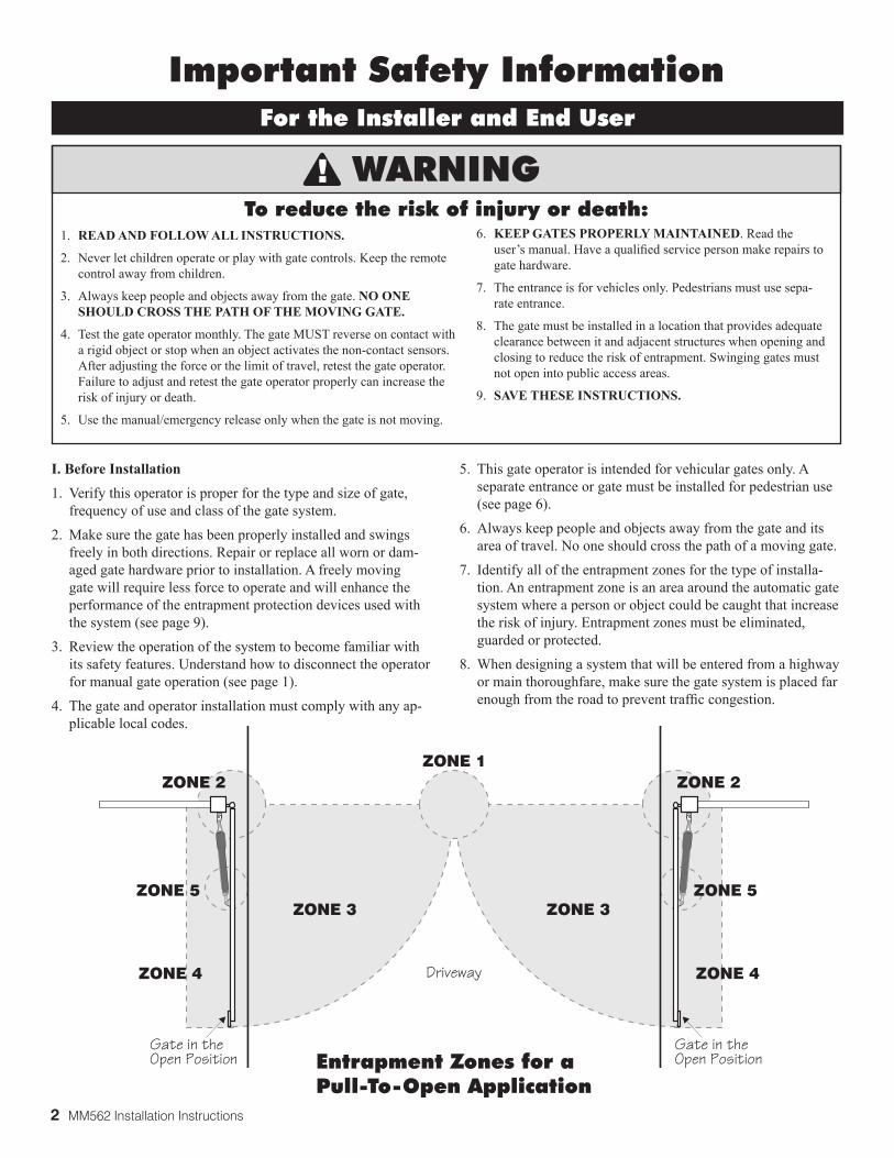
Entrapment Zones for a Pull-To-Open Application
Gate in the �Open Position
Gate in the �Open Position
ZONE 2
ZONE 3
ZONE 4
ZONE 5
Driveway
ZONE 1ZONE 2
ZONE 4
ZONE 5ZONE 3
For the Installer and End User
Important Safety Information
I. Before Installation1. Verify this operator is proper for the type and size of gate,
frequency of use and class of the gate system.
2. Make sure the gate has been properly installed and swings freely in both directions. Repair or replace all worn or dam-aged gate hardware prior to installation. A freely moving gate will require less force to operate and will enhance the performance of the entrapment protection devices used with the system (see page 9).
3. Review the operation of the system to become familiar with its safety features. Understand how to disconnect the operator for manual gate operation (see page 1).
4. The gate and operator installation must comply with any ap-plicable local codes.
5. This gate operator is intended for vehicular gates only. A separate entrance or gate must be installed for pedestrian use (see page 6).
6. Always keep people and objects away from the gate and its area of travel. No one should cross the path of a moving gate.
7. Identify all of the entrapment zones for the type of installa-tion. An entrapment zone is an area around the automatic gate system where a person or object could be caught that increase the risk of injury. Entrapment zones must be eliminated, guarded or protected.
8. When designing a system that will be entered from a highway or main thoroughfare, make sure the gate system is placed far enough from the road to prevent traffic congestion.
WARNING
1. READ AND FOLLOW ALL INSTRUCTIONS.
2. Never let children operate or play with gate controls. Keep the remote control away from children.
3. Always keep people and objects away from the gate. NO ONE SHOULD CROSS THE PATH OF THE MOVING GATE.
4. Test the gate operator monthly. The gate MUST reverse on contact with a rigid object or stop when an object activates the non-contact sensors. After adjusting the force or the limit of travel, retest the gate operator. Failure to adjust and retest the gate operator properly can increase the risk of injury or death.
5. Use the manual/emergency release only when the gate is not moving.
6. KEEP GATES PROPERLY MAINTAINED. Read the user’s manual. Have a qualified service person make repairs to gate hardware.
7. The entrance is for vehicles only. Pedestrians must use sepa-rate entrance.
8. The gate must be installed in a location that provides adequate clearance between it and adjacent structures when opening and closing to reduce the risk of entrapment. Swinging gates must not open into public access areas.
9. SAVE THESE INSTRUCTIONS.
To reduce the risk of injury or death:
MM562 Installation Instructions 3
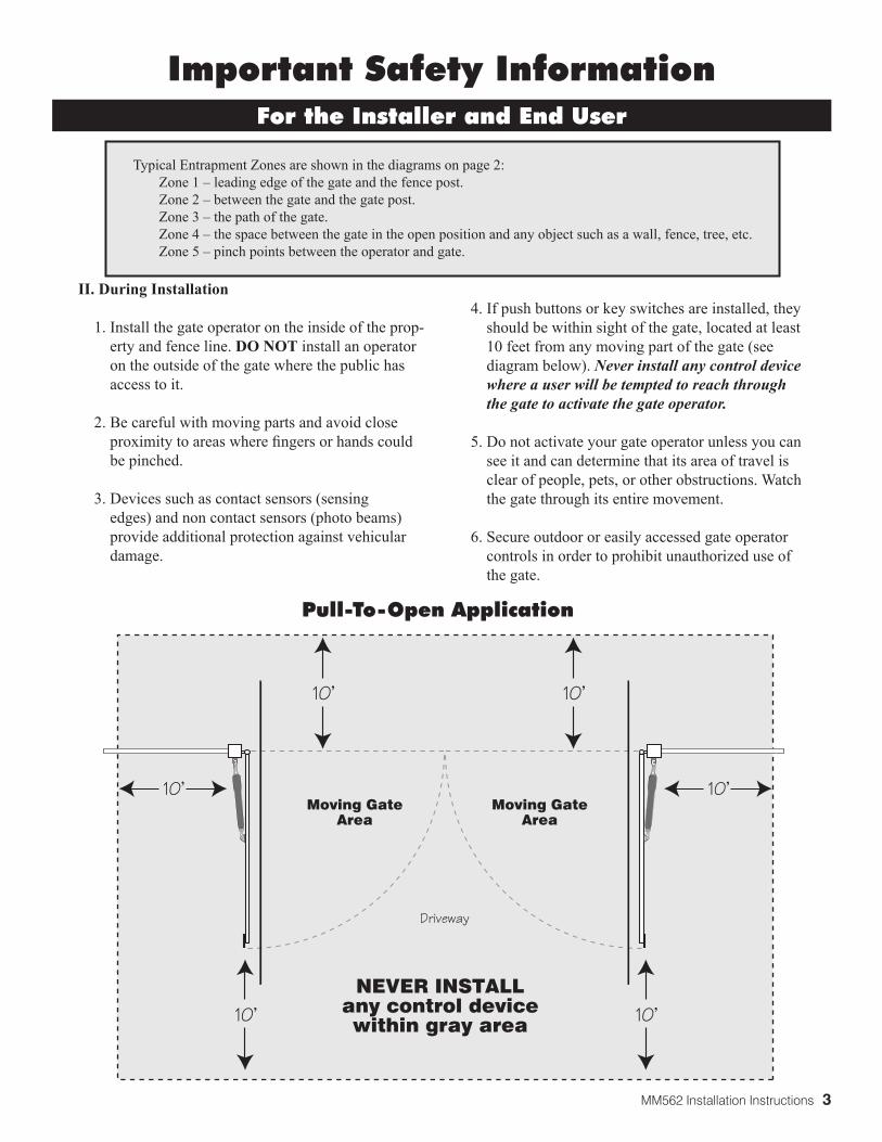
Pull-To-Open Application
Moving GateArea
Moving GateArea
Driveway
10'10'
10'10'
10'10'
NEVER INSTALLany control devicewithin gray area
II. During Installation
1. Install the gate operator on the inside of the prop-erty and fence line. DO NOT install an operator on the outside of the gate where the public has access to it.
2. Be careful with moving parts and avoid close proximity to areas where fingers or hands could be pinched.
3. Devices such as contact sensors (sensing edges) and non contact sensors (photo beams) provide additional protection against vehicular damage.
4. If push buttons or key switches are installed, they should be within sight of the gate, located at least 10 feet from any moving part of the gate (see diagram below). Never install any control device where a user will be tempted to reach through the gate to activate the gate operator.
5. Do not activate your gate operator unless you can see it and can determine that its area of travel is clear of people, pets, or other obstructions. Watch the gate through its entire movement.
6. Secure outdoor or easily accessed gate operator controls in order to prohibit unauthorized use of the gate.
For the Installer and End User
Typical Entrapment Zones are shown in the diagrams on page 2: Zone 1 – leading edge of the gate and the fence post. Zone 2 – between the gate and the gate post. Zone 3 – the path of the gate. Zone 4 – the space between the gate in the open position and any object such as a wall, fence, tree, etc. Zone 5 – pinch points between the operator and gate.
Important Safety Information

4 MM562 Installation Instructions
For the Installer and End User
Important Safety Information
III. After Installation
1. Attach the warning signs (included) to each side of the gate to alert the public of automatic gate operation. It is your responsibility to post warning signs on both sides of your gate. If any of these signs or warning decals becomes damaged, illegible, or missing, replace them immediately. Contact GTO for free replacements.
2. The gate is automatic and could move at any time, posing serious risk of entrapment. No one should be in contact with the gate when it is moving or stationary.
3. Do not attempt to drive into the gate area while the gate is moving; wait until the gate comes to a complete stop.
4. Do not attempt to “beat the gate” while the gate is closing. This is extremely dangerous.
5. Do not allow children or pets near your gate. Never let children operate or play with gate controls. Keep the remote control away from children and unauthorized users; store controls where children and unauthorized users do not have access to them.
6. KEEP GATES PROPERLY MAINTAINED. Always turn power to operator OFF before performing any maintenance. See page 33 for maintenance procedures.
7. To operate this equipment safely, YOU must know how to disconnect the operator for manual gate operation (see page 1). If you have read the instructions and still do not understand how to disconnect the operator, contact the Mighty Mule Service Department.
8. Disconnect the operator ONLY when the power
is TURNED OFF and the gate is NOT moving. 9. Make arrangements with local fire and law
enforcement for emergency access. 10. Distribute and discuss copies of the
IMPORTANT SAFETY INFORMATION section of this manual with all persons authorized to use your gate.
11. IMPORTANT: Save these safety instructions.
Make sure everyone who is using or will be around the gate and gate operator are aware of the dangers associated with automated gate systems. In the event you sell the property with the gate operator or sell the gate operator, provide a copy of these safety instructions to the new owner. Should you need a replacement manual, a copy can be obtained by downloading one from the Mighty Mule web site (www.mightymule.com), by contacting GTO, at 3121 Hartsfield Road, Tallahassee, Florida 32303 or by calling 1-800-543-4283 and requesting a duplicate copy. One will be provided to you.
MM562 Installation Instructions 5
500UL325 SERIES
®
E-Z GATE OPENER1-800-543-GATE (4283)
www.mightymule.com
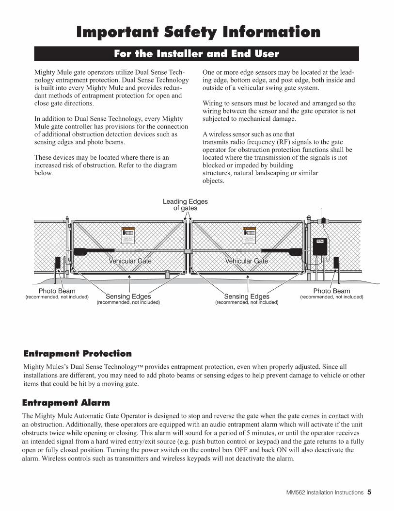
Vehicular GateVehicular Gate
Photo Beam(recommended, not included)
Photo Beam(recommended, not included)Sensing Edges
(recommended, not included)Sensing Edges
(recommended, not included)
Leading Edgesof gates
For the Installer and End User
Important Safety Information
Mighty Mule gate operators utilize Dual Sense Tech-nology entrapment protection. Dual Sense Technology is built into every Mighty Mule and provides redun-dant methods of entrapment protection for open and close gate directions. In addition to Dual Sense Technology, every Mighty Mule gate controller has provisions for the connection of additional obstruction detection devices such as sensing edges and photo beams.
These devices may be located where there is an increased risk of obstruction. Refer to the diagram below.
One or more edge sensors may be located at the lead-ing edge, bottom edge, and post edge, both inside and outside of a vehicular swing gate system. Wiring to sensors must be located and arranged so the wiring between the sensor and the gate operator is not subjected to mechanical damage. A wireless sensor such as one that transmits radio frequency (RF) signals to the gate operator for obstruction protection functions shall be located where the transmission of the signals is not blocked or impeded by building structures, natural landscaping or similar objects.
Entrapment AlarmThe Mighty Mule Automatic Gate Operator is designed to stop and reverse the gate when the gate comes in contact with an obstruction. Additionally, these operators are equipped with an audio entrapment alarm which will activate if the unit obstructs twice while opening or closing. This alarm will sound for a period of 5 minutes, or until the operator receives an intended signal from a hard wired entry/exit source (e.g. push button control or keypad) and the gate returns to a fully open or fully closed position. Turning the power switch on the control box OFF and back ON will also deactivate the alarm. Wireless controls such as transmitters and wireless keypads will not deactivate the alarm.
Entrapment Protection Mighty Mules’s Dual Sense Technology™ provides entrapment protection, even when properly adjusted. Since all installations are different, you may need to add photo beams or sensing edges to help prevent damage to vehicle or other items that could be hit by a moving gate.
6 MM562 Installation Instructions
Warning SignWarning Sign Pedestrian Gate
Bulldog Pedestrian Gate Lock
(recommended, not included)
Vehicular GateVehicular Gate
7 footminimum
Important Safety Information
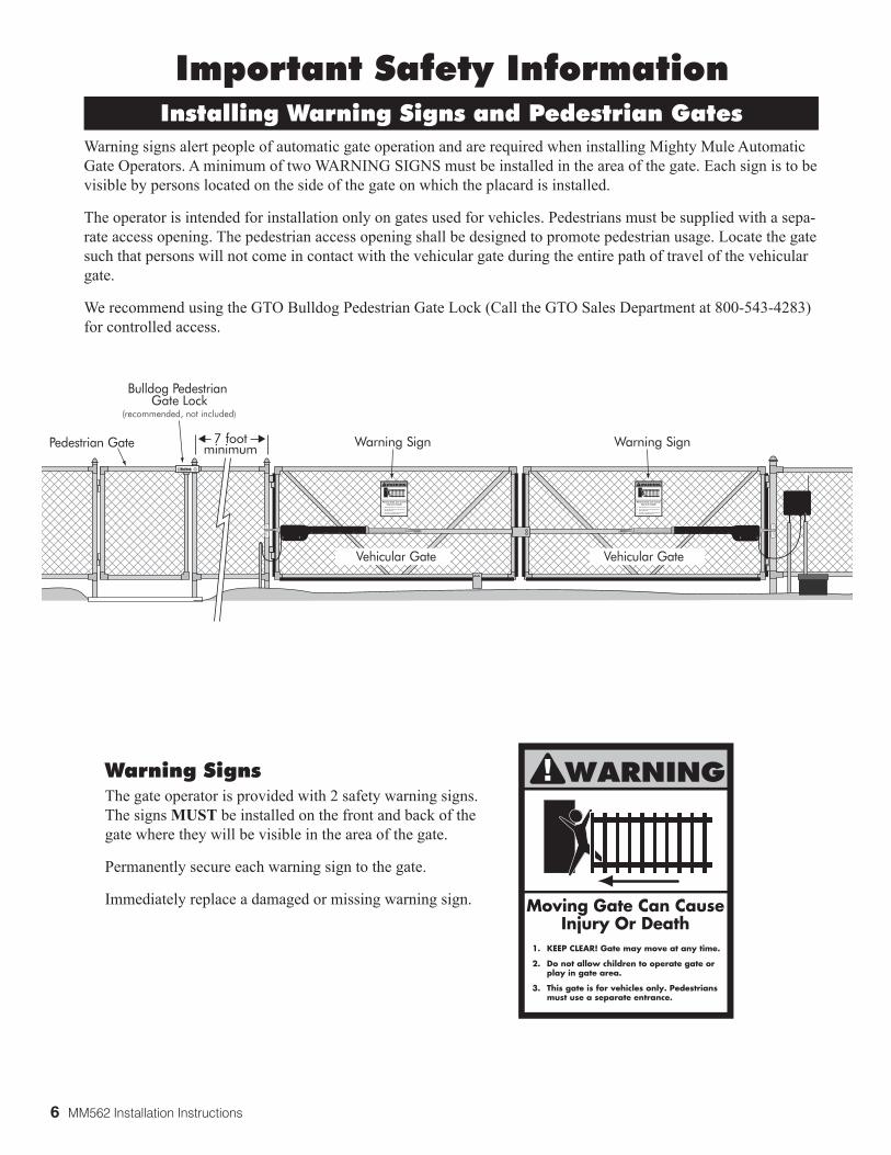
Warning signs alert people of automatic gate operation and are required when installing Mighty Mule Automatic Gate Operators. A minimum of two WARNING SIGNS must be installed in the area of the gate. Each sign is to be visible by persons located on the side of the gate on which the placard is installed.
The operator is intended for installation only on gates used for vehicles. Pedestrians must be supplied with a sepa-rate access opening. The pedestrian access opening shall be designed to promote pedestrian usage. Locate the gate such that persons will not come in contact with the vehicular gate during the entire path of travel of the vehicular gate.
We recommend using the GTO Bulldog Pedestrian Gate Lock (Call the GTO Sales Department at 800-543-4283) for controlled access.
Installing Warning Signs and Pedestrian Gates
Warning SignsThe gate operator is provided with 2 safety warning signs. The signs MUST be installed on the front and back of the gate where they will be visible in the area of the gate.
Permanently secure each warning sign to the gate.
Immediately replace a damaged or missing warning sign.
!
MM562 Installation Instructions 7
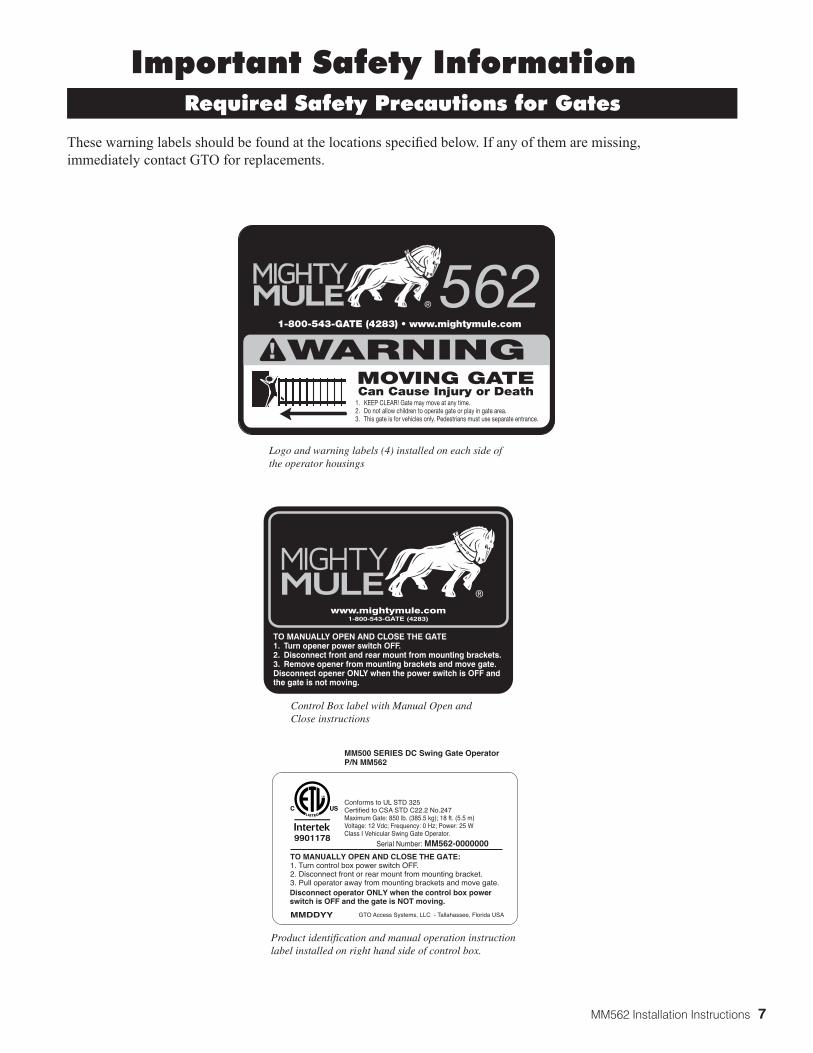
Product identification and manual operation instruction label installed on right hand side of control box.
1. KEEP CLEAR! Gate may move at any time.2. Do not allow children to operate gate or play in gate area.3. This gate is for vehicles only. Pedestrians must use separate entrance.
WARNING!MOVING GATECan Cause Injury or Death
1-800-543-GATE (4283) • www.mightymule.com
562®
Logo and warning labels (4) installed on each side of the operator housings
9901178
TO MANUALLY OPEN AND CLOSE THE GATE:1. Turn control box power switch OFF.2. Disconnect front or rear mount from mounting bracket.3. Pull operator away from mounting brackets and move gate. Disconnect operator ONLY when the control box power switch is OFF and the gate is NOT moving.
Serial Number: MM562-0000000
MMDDYY GTO Access Systems, LLC - Tallahassee, Florida USA
Conforms to UL STD 325Certified to CSA STD C22.2 No.247Maximum Gate: 850 lb. (385.5 kg); 18 ft. (5.5 m)Voltage: 12 Vdc; Frequency: 0 Hz; Power: 25 WClass I Vehicular Swing Gate Operator.
MM500 SERIES DC Swing Gate OperatorP/N MM562
Control Box label with Manual Open and Close instructions
TO MANUALLY OPEN AND CLOSE THE GATE1. Turn opener power switch OFF. 2. Disconnect front and rear mount from mounting brackets.3. Remove opener from mounting brackets and move gate.Disconnect opener ONLY when the power switch is OFF and the gate is not moving.
www.mightymule.com1-800-543-GATE (4283)
®
Important Safety Information
These warning labels should be found at the locations specified below. If any of them are missing, immediately contact GTO for replacements.
Required Safety Precautions for Gates

8 MM562 Installation Instructions
DRIVE
• Low friction screw drive (linear actuator) rated for -5 ºF to +160 ºF (-20 ºC to +71 ºC). • Powered by a 12 V motor with integral case hardened steel gear reducer. Motor speed reduced to 260 rpm. • Maximum opening arc of 110º. Approximate opening time (90º): 20 seconds, depending on weight of gate.
POWER
• The system is powered by two 12 Vdc, 7.0 Ah, sealed, rechargeable acid batteries. • Battery charge is maintained by a18 Vac output transformer or optional solar panel(s). One (1) blade-style control
board fuse rated for 25 A. NOTE: The transformer should not be directly connected to any battery. Do not replace fuses
with higher ampere rated fuses; doing so will void your warranty and may damage your control board. • Battery charge is maintained by GTO Solar Panel Charger kit (10 Watt minimum).
CONTROL
• GTO microprocessor-based control board is set for single leaf, pull-to-open gate installations. DIP switches can be adjusted to accommodate an optional kit for push-to-open gates (see Accessory Catalog).
• A circuit on the control board regulates charging. "Sleep draw" is 40 mA; "active draw" is 2 to 5 A.• Auto-memorization of digital transmitter code. • GTO remote-mounted RF receiver tuned to 318 MHz. • Opener length with push-pull tube fully retracted is 401/4", mounting point to mounting point. Max stroke 20".• Adjustable auto-close timer and Dual Sense Technology stall force.• Power terminal bock accommodates a transformer or solar panels.• DIP switches simplify setup of gate opener.• Accessory terminal block is fully compatible with push button controls, digital keypads, loops, etc.• Control board allows connection of edge sensors and photoelectric sensors.• Audio entrapment alarm sounds if the unit encounters an obstruction twice while opening or closing.
OPERATIONAL CAPACITY• The Gate Capacity Chart shows approximate cycles, per day, you can expect from the Mighty Mule Automatic Gate
Opener when powered with a transformer and 12V battery, prior to the battery depleting to a state where the unit will not function. Actual cycles may vary slightly depending upon the type and condition of gate and installation.
MIGHTY MULE GATE OPENER
Technical Specifications
These specifications are subject to change without notice.
IMPORTANT: BALL BEAR-ING HINGES SHOULD BE USED ON ALL GATES WEIGHING OVER 250 Lbs.
NOTE: "NR" indicates this size and weight combination is not recommended for the Mighty Mule gate openers.
To determine the number of cycles the gate opener will perform using solar panels (see page 22)
Gat
e W
eig
ht
Gate Length
Number of Cycles Per Day
Mighty Mule 562 Gate Capacity /Cycle Chart Estimated number of daily cycles, based on use with a transformer and one(1) 12 Volt battery.
850 lbs.750 lbs.650 lbs.550 lbs.450 lbs.350 lbs.250 lbs.150 lbs.100 lbs.50 lbs.
68737883889398103108113
5’ - 6’
63687378838893981031088’
636873788388939810310’
636873788388939812’
6368737883889314’
63687378838816’
NRNRNRNR
NR636873788318’
NRNRNRNR
NRNRNR
NRNR
NR
NR = NOT RECOMMENDED
MM562 Installation Instructions 9
Preparation of the Gate
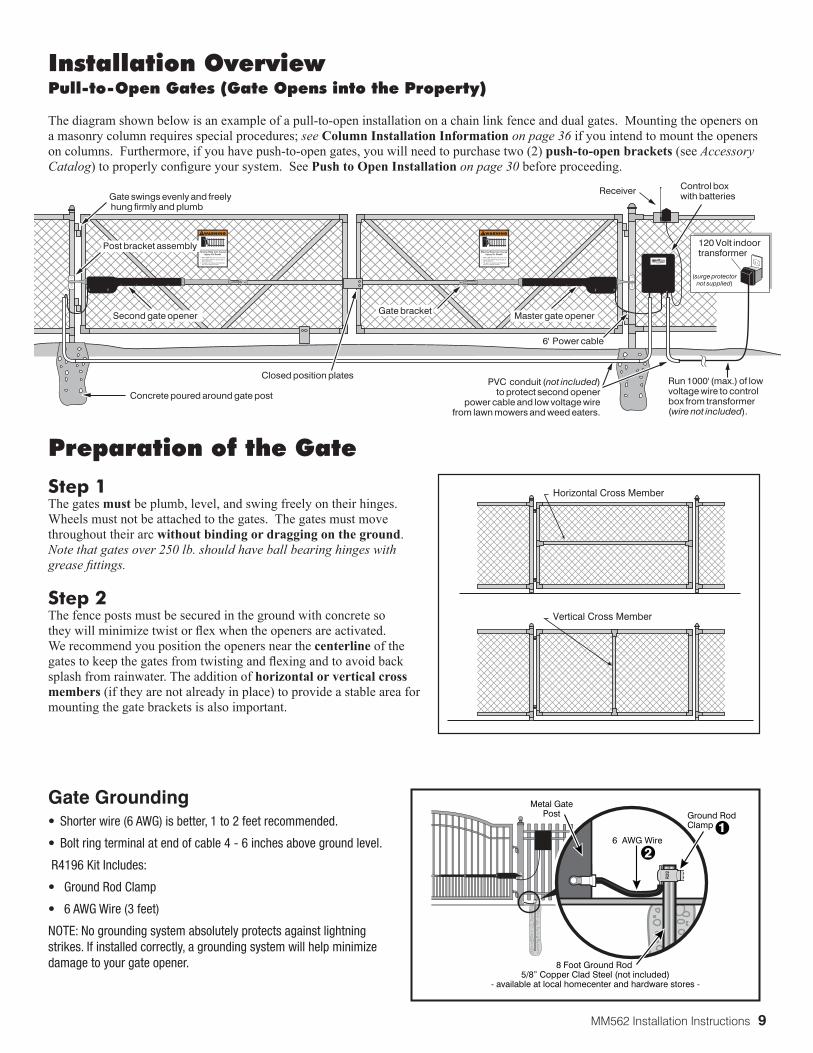
Step 1 The gates must be plumb, level, and swing freely on their hinges. Wheels must not be attached to the gates. The gates must move throughout their arc without binding or dragging on the ground. Note that gates over 250 lb. should have ball bearing hinges with grease fittings.
Step 2 The fence posts must be secured in the ground with concrete so they will minimize twist or flex when the openers are activated. We recommend you position the openers near the centerline of the gates to keep the gates from twisting and flexing and to avoid back splash from rainwater. The addition of horizontal or vertical cross members (if they are not already in place) to provide a stable area for mounting the gate brackets is also important.
Installation OverviewPull-to-Open Gates (Gate Opens into the Property)
The diagram shown below is an example of a pull-to-open installation on a chain link fence and dual gates. Mounting the openers on a masonry column requires special procedures; see Column Installation Information on page 36 if you intend to mount the openers on columns. Furthermore, if you have push-to-open gates, you will need to purchase two (2) push-to-open brackets (see Accessory Catalog) to properly configure your system. See Push to Open Installation on page 30 before proceeding.
Horizontal Cross Member
Vertical Cross Member
500UL325 SERIES
®
E-Z GATE OPENER1-800-543-GATE (4283)
www.mightymule.com
Gate swings evenly and freely hung firmly and plumb
Receiver
PVC conduit (not included)to protect second opener
power cable and low voltage wirefrom lawn mowers and weed eaters.
Control box with batteries
Concrete poured around gate post
6' Power cable
Closed position plates
120 Volt indoortransformer
(surge protectornot supplied)
Second gate opener Master gate opener
Post bracket assembly
Gate bracket
Run 1000' (max.) of lowvoltage wire to controlbox from transformer(wire not included).
Gate Grounding• Shorter wire (6 AWG) is better, 1 to 2 feet recommended.
• Bolt ring terminal at end of cable 4 - 6 inches above ground level.
R4196 Kit Includes:
• Ground Rod Clamp
• 6 AWG Wire (3 feet)
NOTE: No grounding system absolutely protects against lightning strikes. If installed correctly, a grounding system will help minimize damage to your gate opener.
Metal GatePost
6 AWG Wire
8 Foot Ground Rod 5/8” Copper Clad Steel (not included)
- available at local homecenter and hardware stores -
Ground RodClamp
10 MM562 Installation Instructions
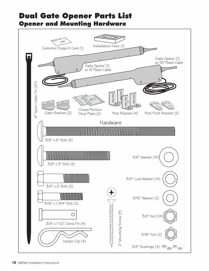
Dual Gate Opener Parts ListOpener and Mounting Hardware
Hairpin Clip (4)
3/8" x 1-1/2" Clevis Pin (4)
5/16" x 1-3/4" Bolt (2)
3/8" x 2" Bolt (2)
3/8" x 3" Bolt (4)
3/8" x 8" Bolt (8)
8" N
ylon
Cab
le T
ie (
20)
3/8" Washer (18)
3/8" Lock Washer (14)
5/16" Washer (2)
3/8" Nut (14)
5/16" Nut (2)
Hardware
Gate Opener (1)w/ 6' Power Cable
Gate Opener (1)w/ 32' Power Cable
Gate Bracket (2) Post Pivot Bracket (2)
Customer Support Card (1)
Post Bracket (4)Closed PositionStop Plate (2)
2" M
ount
ing
Scr
ew (
5)
®
E-Z GATE OPENER
3/8" Bushings (4)
Installation Video (1)
MM562 Installation Instructions 11
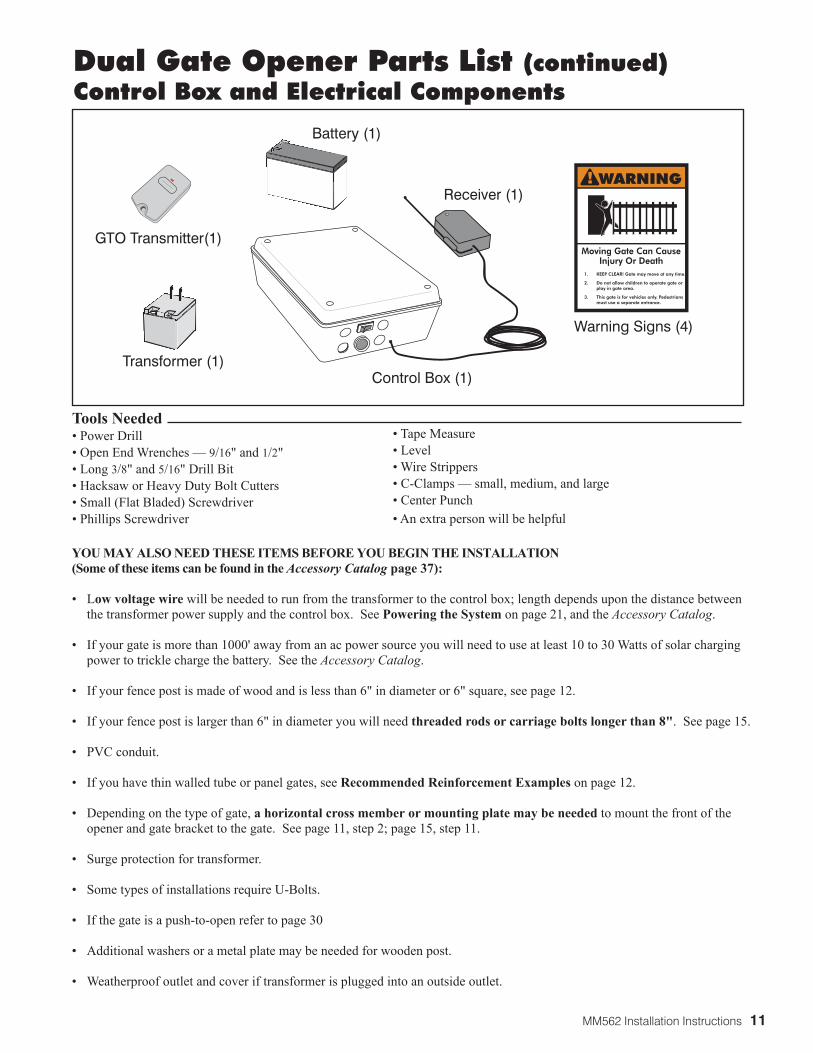
Tools Needed• Power Drill• Open End Wrenches — 9/16" and 1/2"• Long 3/8" and 5/16" Drill Bit• Hacksaw or Heavy Duty Bolt Cutters• Small (Flat Bladed) Screwdriver• Phillips Screwdriver
Dual Gate Opener Parts List (continued)Control Box and Electrical Components
Transformer (1)
Battery (1)
Control Box (1)
Warning Signs (4)
GTO Transmitter(1)
1. KEEP CLEAR! Gate may move at any time.
2. Do not allow children to operate gate or play in gate area.
3. This gate is for vehicles only. Pedestrians must use a separate entrance.
Moving Gate Can CauseInjury Or Death
WARNING!Receiver (1)
• Tape Measure• Level• Wire Strippers• C-Clamps — small, medium, and large• Center Punch• An extra person will be helpful
YOU MAY ALSO NEED THESE ITEMS BEFORE YOU BEGIN THE INSTALLATION (Some of these items can be found in the Accessory Catalog page 37):
• Low voltage wire will be needed to run from the transformer to the control box; length depends upon the distance between the transformer power supply and the control box. See Powering the System on page 21, and the Accessory Catalog.
• If your gate is more than 1000' away from an ac power source you will need to use at least 10 to 30 Watts of solar charging power to trickle charge the battery. See the Accessory Catalog.
• If your fence post is made of wood and is less than 6" in diameter or 6" square, see page 12.
• If your fence post is larger than 6" in diameter you will need threaded rods or carriage bolts longer than 8". See page 15. • PVC conduit.
• If you have thin walled tube or panel gates, see Recommended Reinforcement Examples on page 12.
• Depending on the type of gate, a horizontal cross member or mounting plate may be needed to mount the front of the opener and gate bracket to the gate. See page 11, step 2; page 15, step 11.
• Surge protection for transformer.
• Some types of installations require U-Bolts.
• If the gate is a push-to-open refer to page 30
• Additional washers or a metal plate may be needed for wooden post.
• Weatherproof outlet and cover if transformer is plugged into an outside outlet.
12 MM562 Installation Instructions
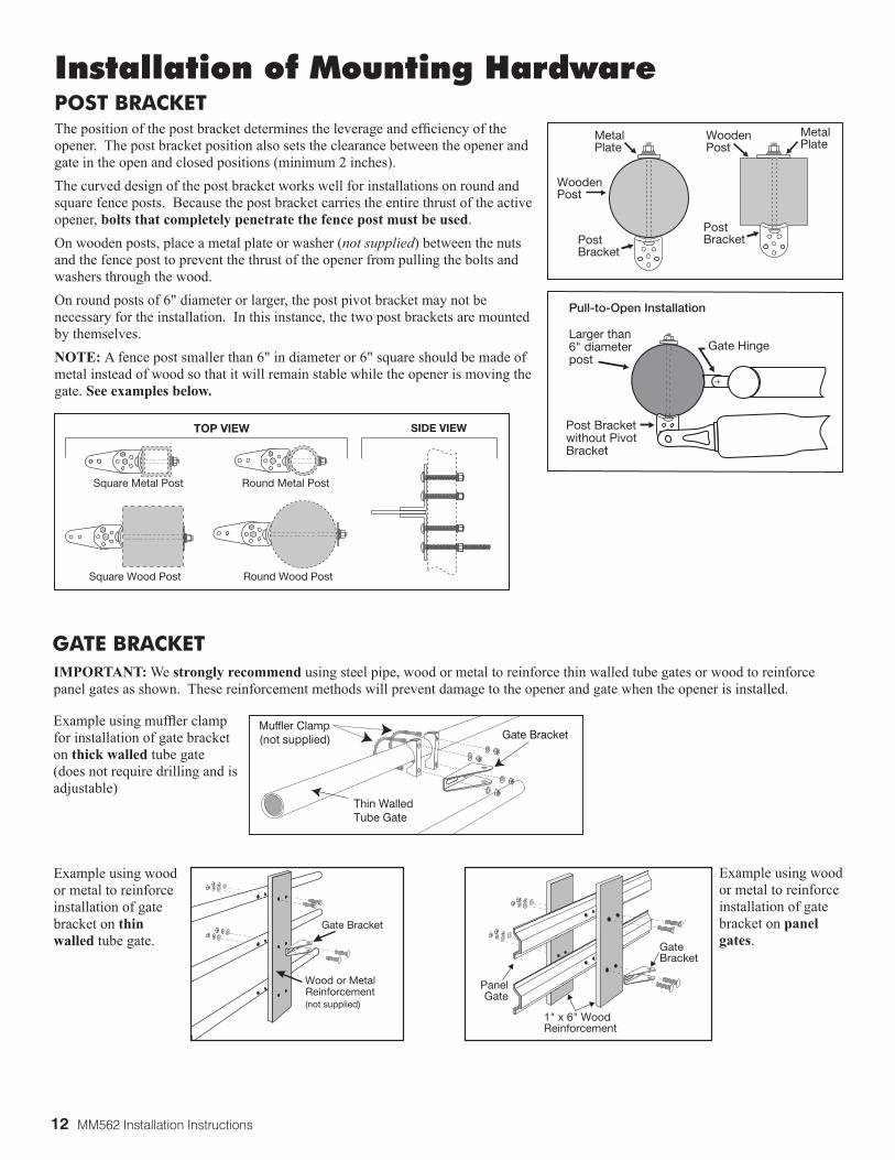
Installation of Mounting HardwarePOST BRACKETThe position of the post bracket determines the leverage and efficiency of the opener. The post bracket position also sets the clearance between the opener and gate in the open and closed positions (minimum 2 inches).The curved design of the post bracket works well for installations on round and square fence posts. Because the post bracket carries the entire thrust of the active opener, bolts that completely penetrate the fence post must be used.On wooden posts, place a metal plate or washer (not supplied) between the nuts and the fence post to prevent the thrust of the opener from pulling the bolts and washers through the wood.On round posts of 6" diameter or larger, the post pivot bracket may not be necessary for the installation. In this instance, the two post brackets are mounted by themselves.NOTE: A fence post smaller than 6" in diameter or 6" square should be made of metal instead of wood so that it will remain stable while the opener is moving the gate. See examples below.
Post Bracket
MetalPlate
WoodenPost
WoodenPost
MetalPlate
Post Bracket
Gate Hinge
Post Bracketwithout PivotBracket
Pull-to-Open Installation
Larger than 6" diameter post
GATE BRACKET IMPORTANT: We strongly recommend using steel pipe, wood or metal to reinforce thin walled tube gates or wood to reinforce panel gates as shown. These reinforcement methods will prevent damage to the opener and gate when the opener is installed.
Thin WalledTube Gate
Gate BracketMuffler Clamp(not supplied)
Gate Bracket
Wood or MetalReinforcement(not supplied)
GateBracket
PanelGate
1" x 6" WoodReinforcement
Example using muffler clamp for installation of gate bracket on thick walled tube gate (does not require drilling and is adjustable)
Example using wood or metal to reinforce installation of gate bracket on thin walled tube gate.
Example using wood or metal to reinforce installation of gate bracket on panel gates.
Round Metal PostSquare Metal Post
Square Wood Post Round Wood Post
SIDE VIEWTOP VIEW
MM562 Installation Instructions 13
Clevis Pin
Hairpin Clip
Post Bracket Assembly
Rear Mount
Opener
Bushing
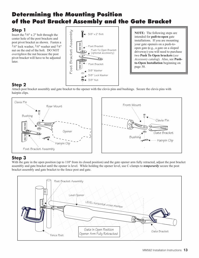
Determining the Mounting Position of the Post Bracket Assembly and the Gate Bracket
Step 3 With the gate in the open position (up to 110º from its closed position) and the gate opener arm fully retracted, adjust the post bracket assembly and gate bracket until the opener is level. While holding the opener level, use C-clamps to temporarily secure the post bracket assembly and gate bracket to the fence post and gate.
Step 1 Insert the 3/8" x 2" bolt through the center hole of the post brackets and post pivot bracket as shown. Fasten a 3/8" lock washer, 3/8" washer and 3/8" nut on the end of the bolt. DO NOT overtighten the nut because the post pivot bracket will have to be adjusted later.
Step 2 Attach post bracket assembly and gate bracket to the opener with the clevis pins and bushings. Secure the clevis pins with hairpin clips.
Level Opener
Fence Post
Gate In Open PositionOpener Arm Fully Retracted
LEVEL horizontal cross member
Post Bracket Assembly
Gate Bracket
Clevis Pin
Hairpin ClipBushing
Gate Bracket
Front Mount
3/8" x 2" Bolt
3/8" Nut
Push-To-Open Bracket�(optional accessory)
Post Bracket
Post Bracket
3/8" Lock WasherP
ost
Bra
cket
Ass
embl
y3/8" Washer
NOTE: The following steps are intended for pull-to-open gate installations. If you are mounting your gate openers on a push-to-open gate (e.g., a gate on a sloped driveway) you will need to purchase two Push To Open brackets (see Accessory catalog). Also, see Push-to-Open Installation beginning on page 30.
14 MM562 Installation Instructions
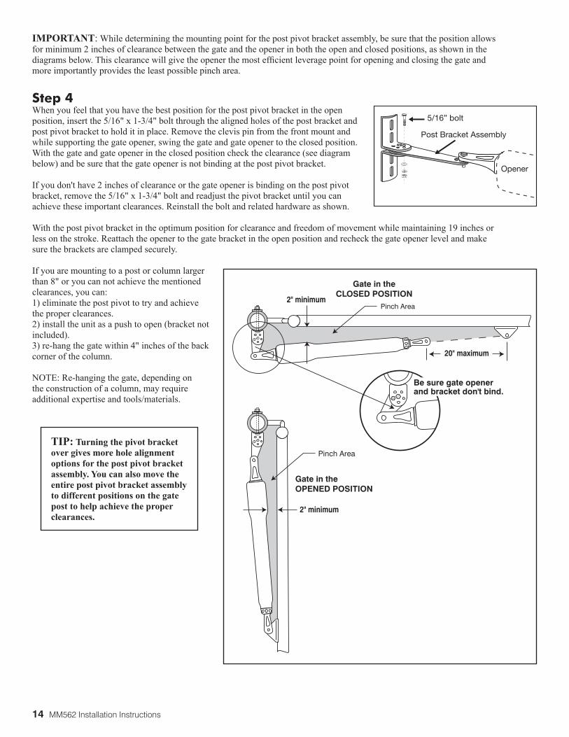
Gate in theCLOSED POSITION
Pinch Area
Gate in theOPENED POSITION
Pinch Area
2" minimum
2" minimum
20" maximum
Be sure gate opener and bracket don't bind.
Step 4 When you feel that you have the best position for the post pivot bracket in the open position, insert the 5/16" x 1-3/4" bolt through the aligned holes of the post bracket and post pivot bracket to hold it in place. Remove the clevis pin from the front mount and while supporting the gate opener, swing the gate and gate opener to the closed position. With the gate and gate opener in the closed position check the clearance (see diagram below) and be sure that the gate opener is not binding at the post pivot bracket.
If you don't have 2 inches of clearance or the gate opener is binding on the post pivot bracket, remove the 5/16" x 1-3/4" bolt and readjust the pivot bracket until you can achieve these important clearances. Reinstall the bolt and related hardware as shown.
With the post pivot bracket in the optimum position for clearance and freedom of movement while maintaining 19 inches or less on the stroke. Reattach the opener to the gate bracket in the open position and recheck the gate opener level and make sure the brackets are clamped securely.
If you are mounting to a post or column larger than 8" or you can not achieve the mentioned clearances, you can:1) eliminate the post pivot to try and achieve the proper clearances. 2) install the unit as a push to open (bracket not included). 3) re-hang the gate within 4" inches of the back corner of the column.
NOTE: Re-hanging the gate, depending on the construction of a column, may require additional expertise and tools/materials.
IMPORTANT: While determining the mounting point for the post pivot bracket assembly, be sure that the position allows for minimum 2 inches of clearance between the gate and the opener in both the open and closed positions, as shown in the diagrams below. This clearance will give the opener the most efficient leverage point for opening and closing the gate and more importantly provides the least possible pinch area.
TIP: Turning the pivot bracket over gives more hole alignment options for the post pivot bracket assembly. You can also move the entire post pivot bracket assembly to different positions on the gate post to help achieve the proper clearances.
5/16” bolt
Post Bracket Assembly
Opener
MM562 Installation Instructions 15
Installing the Post Bracket Assembly and Gate Bracket
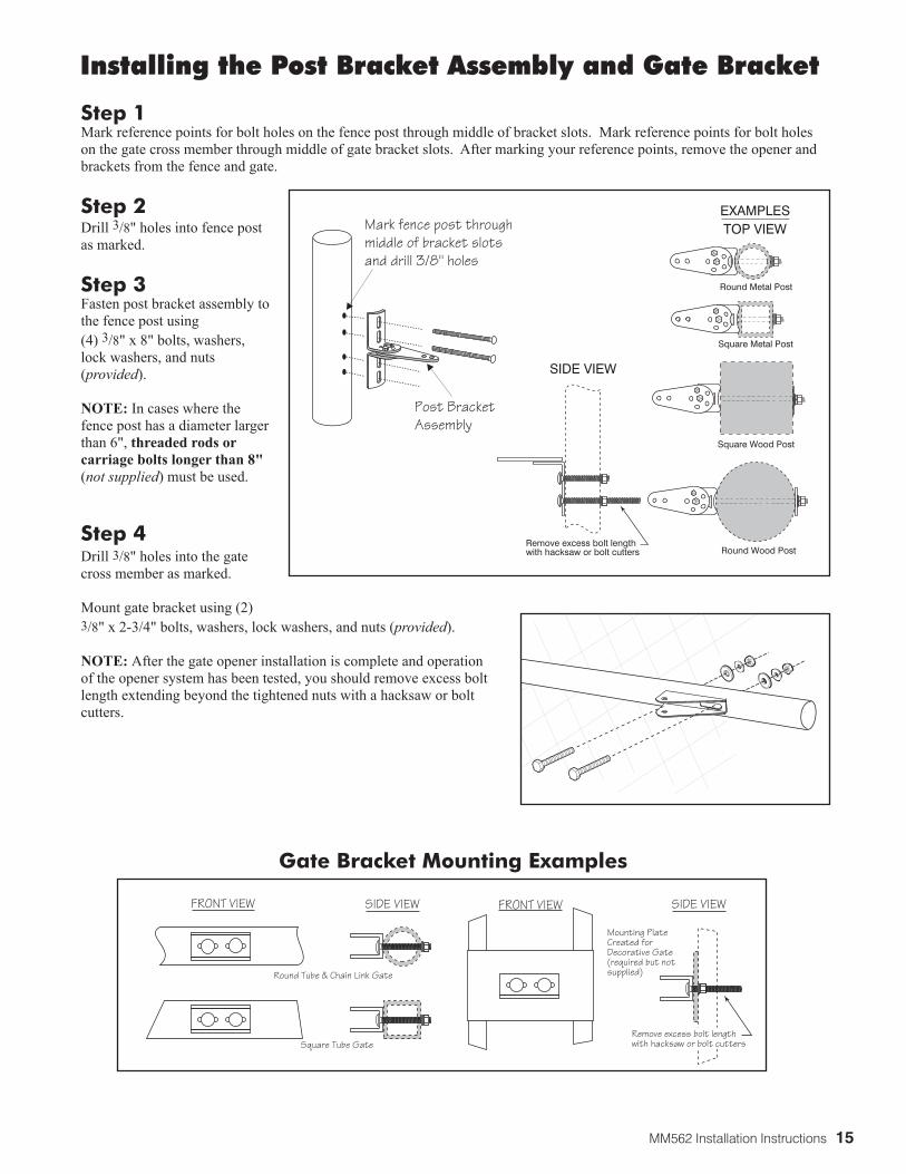
Step 1 Mark reference points for bolt holes on the fence post through middle of bracket slots. Mark reference points for bolt holes on the gate cross member through middle of gate bracket slots. After marking your reference points, remove the opener and brackets from the fence and gate.
Step 2 Drill 3/8" holes into fence post as marked.
Step 3 Fasten post bracket assembly to the fence post using(4) 3/8" x 8" bolts, washers, lock washers, and nuts (provided).
NOTE: In cases where the fence post has a diameter larger than 6", threaded rods or carriage bolts longer than 8"(not supplied) must be used.
Step 4 Drill 3/8" holes into the gate cross member as marked.
Mount gate bracket using (2)3/8" x 2-3/4" bolts, washers, lock washers, and nuts (provided).
NOTE: After the gate opener installation is complete and operation of the opener system has been tested, you should remove excess bolt length extending beyond the tightened nuts with a hacksaw or bolt cutters.
Gate Bracket Mounting Examples
Post Bracket�Assembly
Mark fence post through �middle of bracket slots�and drill 3/8" holes
Round Metal Post
Round Wood Post
Square Metal Post
Square Wood Post
Remove excess bolt length with hacksaw or bolt cutters
SIDE VIEW
TOP VIEWEXAMPLES
Round Tube & Chain Link Gate
Square Tube Gate
Mounting Plate Created for Decorative Gate(required but notsupplied)
Remove excess bolt length with hacksaw or bolt cutters
FRONT VIEW SIDE VIEW FRONT VIEW SIDE VIEW
16 MM562 Installation Instructions
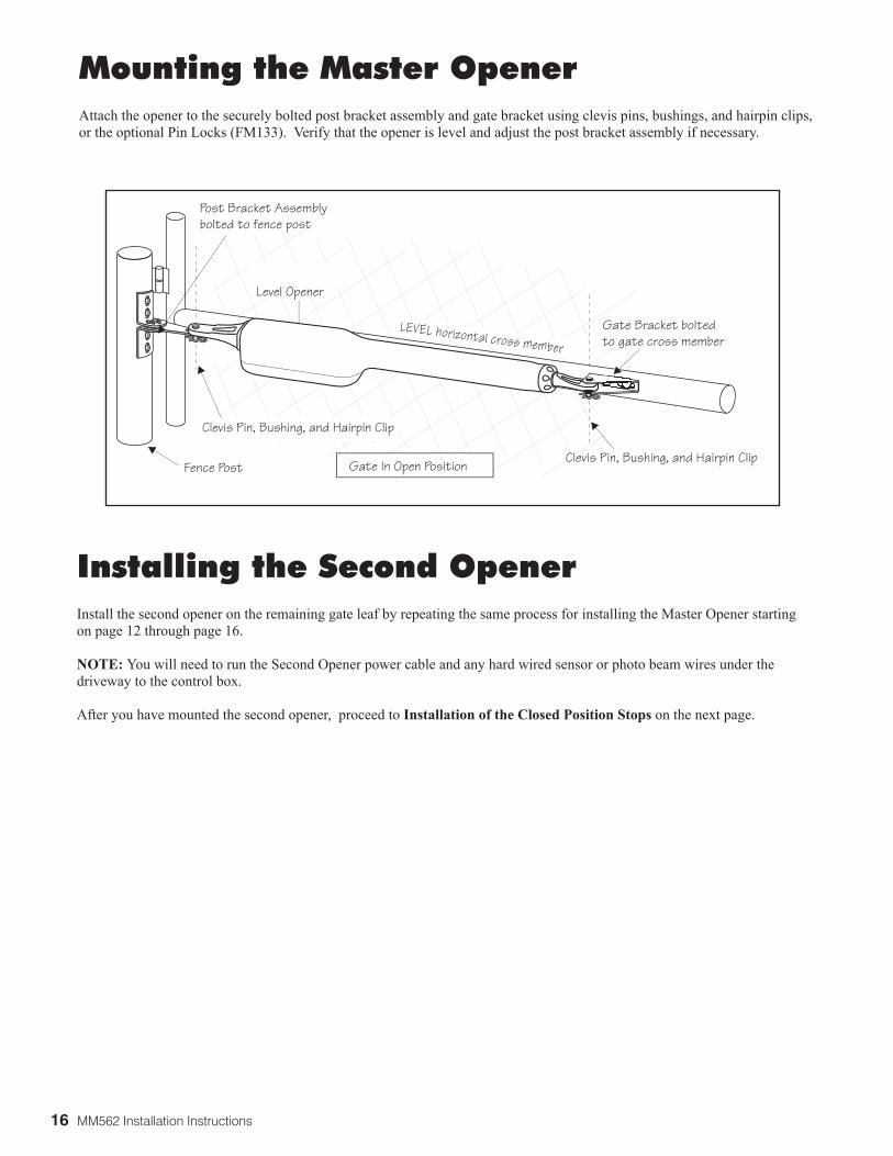
Mounting the Master OpenerAttach the opener to the securely bolted post bracket assembly and gate bracket using clevis pins, bushings, and hairpin clips, or the optional Pin Locks (FM133). Verify that the opener is level and adjust the post bracket assembly if necessary.
Installing the Second OpenerInstall the second opener on the remaining gate leaf by repeating the same process for installing the Master Opener starting on page 12 through page 16.
NOTE: You will need to run the Second Opener power cable and any hard wired sensor or photo beam wires under the driveway to the control box.
After you have mounted the second opener, proceed to Installation of the Closed Position Stops on the next page.
Level Opener
Gate In Open Position
LEVEL horizontal cross member
Post Bracket Assembly bolted to fence post
Clevis Pin, Bushing, and Hairpin Clip
Clevis Pin, Bushing, and Hairpin Clip
Gate Bracket bolted to gate cross member
Fence Post
MM562 Installation Instructions 17
Closed Position �Stop Plates
Gate Hinge
CONTROL BOX
Gate Hinge
The gate leaf can open�up to 110˚ (max.)
Optional Ground Stop�(beneath gate)
The gate leaf can open�up to 110˚ (max.)
MASTER GATE SLAVE GATE
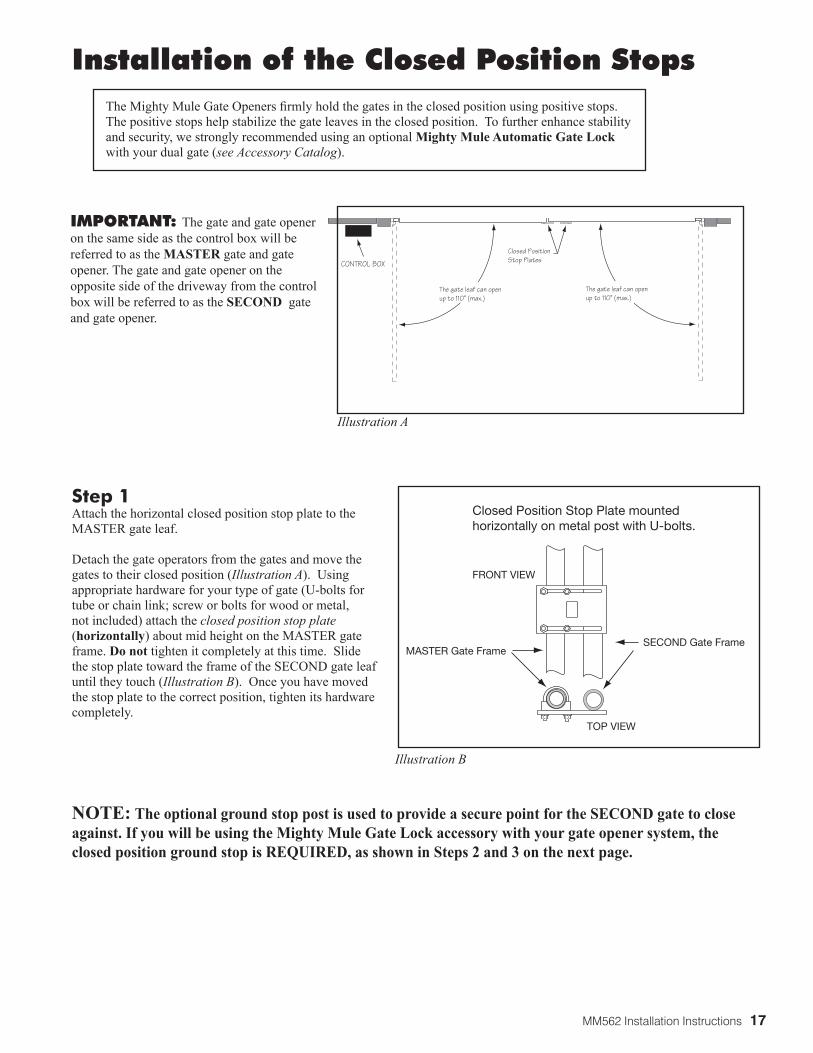
Installation of the Closed Position StopsThe Mighty Mule Gate Openers firmly hold the gates in the closed position using positive stops. The positive stops help stabilize the gate leaves in the closed position. To further enhance stability and security, we strongly recommended using an optional Mighty Mule Automatic Gate Lock with your dual gate (see Accessory Catalog).
IMPORTANT: The gate and gate opener on the same side as the control box will be referred to as the MASTER gate and gate opener. The gate and gate opener on the opposite side of the driveway from the control box will be referred to as the SECOND gate and gate opener.
Step 1Attach the horizontal closed position stop plate to the MASTER gate leaf.
Detach the gate operators from the gates and move the gates to their closed position (Illustration A). Using appropriate hardware for your type of gate (U-bolts for tube or chain link; screw or bolts for wood or metal, not included) attach the closed position stop plate (horizontally) about mid height on the MASTER gate frame. Do not tighten it completely at this time. Slide the stop plate toward the frame of the SECOND gate leaf until they touch (Illustration B). Once you have moved the stop plate to the correct position, tighten its hardware completely.
NOTE: The optional ground stop post is used to provide a secure point for the SECOND gate to close against. If you will be using the Mighty Mule Gate Lock accessory with your gate opener system, the closed position ground stop is REQUIRED, as shown in Steps 2 and 3 on the next page.
Illustration B
Closed Position Stop Plate mounted horizontally on metal post with U-bolts.
SECOND Gate FrameMASTER Gate Frame
TOP VIEW
FRONT VIEW
Illustration A
18 MM562 Installation Instructions
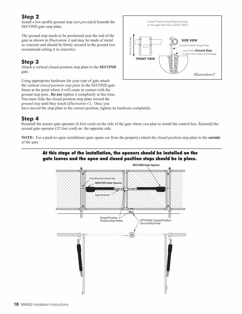
Step 3 Attach a vertical closed position stop plate to the SECOND gate.
Using appropriate hardware for your type of gate attach the vertical closed position stop plate to the SECOND gate frame at the point where it will come in contact with the ground stop post.. Do not tighten it completely at this time. You must slide the closed position stop plate toward the ground stop until they touch (Illustration C). Once you have moved the stop plate to the correct position, tighten its hardware completely.
Step 4 Reinstall the master gate operator (6 foot cord) on the side of the gate where you plan to install the control box. Reinstall the second gate operator (32 foot cord) on the opposite side.
NOTE: For a push-to-open installation (gate opens out from the property) attach the closed position stop plate to the outside of the gate.
Post Bracket Assembly
Gate Bracket
MASTER Gate Opener
Closed Position Positive Stop Plates
SECOND Gate Opener
OPTIONAL Closed Position Ground Stop Post
Step 2 Install a low profile ground stop (not provided) beneath the SECOND gate stop plate.
The ground stop needs to be positioned near the end of the gate as shown in Illustration A and may be made of metal or concrete and should be firmly secured in the ground (we recommend setting it in concrete).
Closed Position Stop Plate mounted�on the gate leaf that CLOSES FIRST
Closed Position Stop Plate��
Low Profile Ground Stopin Near the Center of Driveway
FRONT VIEW
SIDE VIEW
Mou
nt V
erti
cally
Illustration C
At this stage of the installation, the openers should be installed on the gate leaves and the open and closed position stops should be in place.
MM562 Installation Instructions 19
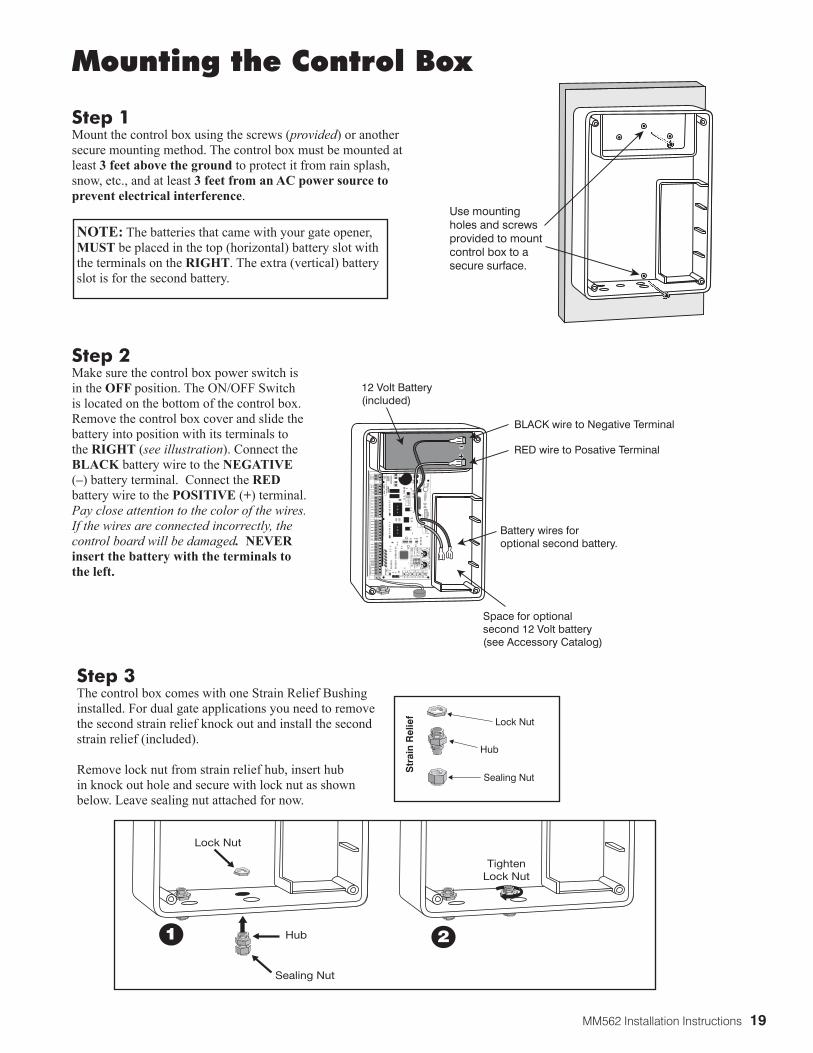
Use mountingholes and screwsprovided to mount control box to a secure surface.
Step 2 Make sure the control box power switch is in the OFF position. The ON/OFF Switch is located on the bottom of the control box. Remove the control box cover and slide the battery into position with its terminals to the RIGHT (see illustration). Connect the BLACK battery wire to the NEGATIVE (–) battery terminal. Connect the RED battery wire to the POSITIVE (+) terminal. Pay close attention to the color of the wires. If the wires are connected incorrectly, the control board will be damaged. NEVER insert the battery with the terminals to the left.
Mounting the Control Box
Step 3 The control box comes with one Strain Relief Bushing installed. For dual gate applications you need to remove the second strain relief knock out and install the second strain relief (included).
Remove lock nut from strain relief hub, insert hub in knock out hole and secure with lock nut as shown below. Leave sealing nut attached for now.
Step 1 Mount the control box using the screws (provided) or another secure mounting method. The control box must be mounted at least 3 feet above the ground to protect it from rain splash, snow, etc., and at least 3 feet from an AC power source to prevent electrical interference.
25FU
SEB
AT
T+
BA
TT-
1 2 3 4
ON DIP
STAT
US
LEAR
N R
MT
REC
EIVER
LEAR
NM
AST
LIMIT
LEAR
NSLV
LIMIT
S3S4
ALM
S2
OFF
SOFT
STAR
T O
FFW
AR
NIN
G O
FFO
PEN
PU
LLSLV
OP
EN D
LY.
MO
DE1
OFF
MO
DE2
OFF
ON
ON
PU
SHSIM
ULT.
ON
ON
12
0M
INM
AX
CH
AR
GIN
G
PW
R IN
GTO
RC
VR
.
WHT
BLU
BRN
ORG
RED
BLK
GRN
WHT
BLU
BRN
ORG
RED
BLK
GRN
COM
GRN
BLK
RED
CYCLE
SAFETY
EXIT
SHADOW
OPENEDGE
COM
GTO
TR
AN
SFLO
CK
PW
RA
UX
RLY
PO
WER
INP
UTS
CO
NT
RO
LO
UT
PU
TS
MA
STER
CA
BLE
SLAV
E CA
BLE
CO
NT
RO
L INP
UTS
AU
TO C
LOSE TIM
E STA
LL FOR
CE
CLOSEEDGE
18 VA
Co
rSO
LAR
GTO
LOC
K
AU
X
Battery wires foroptional second battery.
BLACK wire to Negative Terminal
RED wire to Posative Terminal
12 Volt Battery(included)
Space for optional second 12 Volt battery(see Accessory Catalog)
Sealing Nut
Hub
Lock Nut
Str
ain
Rel
ief
NOTE: The batteries that came with your gate opener, MUST be placed in the top (horizontal) battery slot with the terminals on the RIGHT. The extra (vertical) battery slot is for the second battery.
Lock Nut
TightenLock Nut
Hub
Sealing Nut
1 2
20 MM562 Installation Instructions
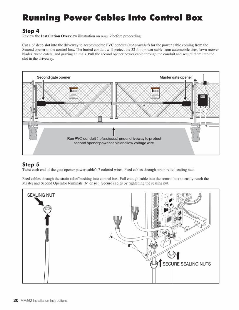
Step 5Twist each end of the gate opener power cable’s 7 colored wires. Feed cables through strain relief sealing nuts.
Feed cables through the strain relief bushing into control box. Pull enough cable into the control box to easily reach the Master and Second Operator terminals (6" or so ). Secure cables by tightening the sealing nut.
Running Power Cables Into Control BoxStep 4Review the Installation Overview illustration on page 9 before proceeding. Cut a 6" deep slot into the driveway to accommodate PVC conduit (not provided) for the power cable coming from the Second opener to the control box. The buried conduit will protect the 32 foot power cable from automobile tires, lawn mower blades, weed eaters, and grazing animals. Pull the second opener power cable through the conduit and secure them into the slot in the driveway.
15FU
SEBATT+
BATT-
1 2 3 4ON
STATUS
LEARN
RMT
RECEIVER
LEARN
MA
ST LIMIT
LEARN
SLV LIM
IT
S3
S4
ALM
S2
OFFSO
FT START O
FFW
ARN
ING
OFF
OPEN
PULL
SLV O
PEN D
LY.
MO
DE1 O
FFM
OD
E2 OFF
ONO
NPUSH
SIMU
LT.
ONO
N
120M
INM
AX
GTO
RCVR.
WHT
BLU
BRN
ORG
RED
BLK
GRN
WHT
BLU
BRN
ORG
RED
BLK
GRN
COM
GRN
BLK
RED
CYCLE
SAFETY
EXIT
SHADOW
OPEN
EDGE
COM
AU
XRLY
MA
STER CABLE
SECON
D CA
BLECO
NTRO
L INPU
TS
AUTO
CLOSE TIM
E STA
LL FORCE
CLOSE
EDGE
GTOLO
CKAU
X
6”
SECURE SEALING NUTS
SEALING NUT
500UL325 SERIES
®
E-Z GATE OPENER1-800-543-GATE (4283)
www.mightymule.com
Second gate opener Master gate opener
Run PVC conduit (not included) under driveway to protect second opener power cable and low voltage wire.
MM562 Installation Instructions 21
Power Cable from theMaster Operator Arm
RE
CE
IVE
R
GTO
RC
VR
.
WHT
BLU
BRN
ORG
RED
BLK
GRN
COM
GRN
BLK
RED
CYCLE
SAFETY
EXIT
SHADOW
OPENEDGE
COM
MA
ST
ER
OP
ER
ATO
RC
ON
TR
OL IN
PU
TSCLOSE
EDGE
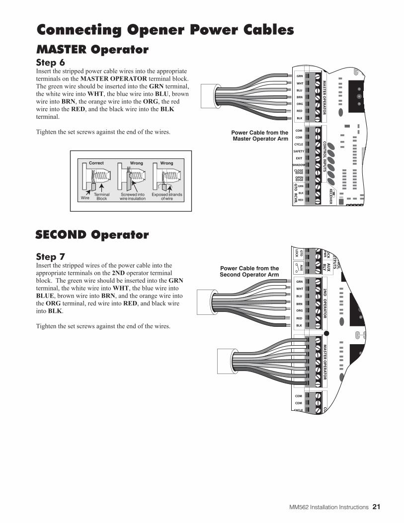
Step 6Insert the stripped power cable wires into the appropriate terminals on the MASTER OPERATOR terminal block. The green wire should be inserted into the GRN terminal, the white wire into WHT, the blue wire into BLU, brown wire into BRN, the orange wire into the ORG, the red wire into the RED, and the black wire into the BLK terminal.
Tighten the set screws against the end of the wires.
Correct
WireTerminal
Block
Wrong Wrong
Exposed strandsof wire
Screwed intowire insulation
Connecting Opener Power CablesMASTER Operator
Step 7Insert the stripped wires of the power cable into the appropriate terminals on the 2ND operator terminal block. The green wire should be inserted into the GRN terminal, the white wire into WHT, the blue wire into BLUE, brown wire into BRN, and the orange wire into the ORG terminal, red wire into RED, and black wire into BLK.
Tighten the set screws against the end of the wires.
SECOND Operator
Power Cable from theSecond Operator Arm
WHT
BLU
BRN
ORG
RED
BLK
GRN
WHT
BLU
BRN
ORG
RED
BLK
GRN
COM
CYCLE
COM
LOC
KP
WR
AU
XR
LY
CO
NT
RO
LO
UT
PU
TS
MA
ST
ER
OP
ER
ATO
R2
ND
OP
ER
ATO
RC
ON
GTO
LOC
K
AU
X

22 MM562 Installation Instructions
OPTIONAL Solar Panels and Gate Activity
Powering the System Installation of the Transformer
IMPORTANT: • Never connect the transformer and a solar panel to the opener control board at the same
time. It will damage the control board. • The transformer is designed and intended for indoor use. If the transformer can be plugged only
into an outside electrical outlet, a weatherproof cover or housing (available at local electrical supply stores) must be used.
• All low voltage wire used with the Mighty Mule Gate Opener must be 16 gauge dual conductor, stranded, direct burial wire (see page 22 and the accessory pages). Do not run more than 1000 feet of wire.
• If your gate is more than 1000 ft. from an ac power source, you will need to use at least one 10 watt Solar Panel to charge the battery (see the accessory pages). Refer to the Solar Panels and Gate Activity chart below.
Step 1 Make sure the power switch is OFF before proceeding to the next step.
Step 2Select the electrical outlet into which you will plug the transformer. Measure the distance from this outlet to the control box following the path where the wire will be laid. After you have measured how much wire is needed, cut the wire to the appropriate length.
ON/OFF Switch
The table and map illustrate the maximum number of gate cycles to expect per day in a particular area when using from 10 to 30 watts of solar charging power, prior to the battery depleting to a state where
the unit will not function.. (see Accessory Catalog). The figures shown are for winter (minimum sunlight) and do not account for the use of any accessory items. Accessories connected to your system will draw additional power from the battery.
NOTE: A maximum of 30 watts of solar charging power can be connected to the Mighty Mule Gate Opener. Consult Solar Panel Installation Instructions for further information.
Winter Ratings Zone 1 Zone 2 Zone 3
12 v dual gate (10 watts) solar charger 4 8 1312 v dual gate (15 watts) solar charger 7 13 2012 v dual gate (20 watts) solar charger 10 18 2712 v dual gate (25 watts) solar charger 13 23 3412 v dual gate (30 watts) solar charger 16 28 41
MM562 Installation Instructions 23
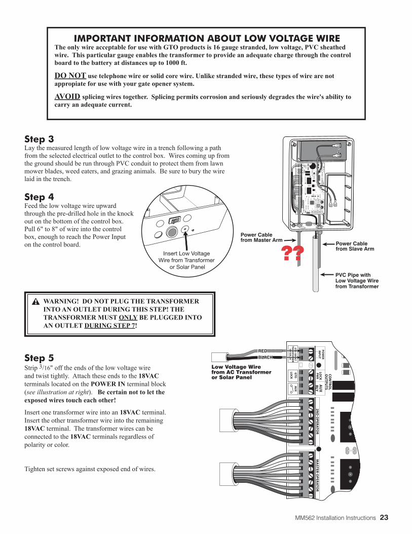
Step 5Strip 3/16" off the ends of the low voltage wire and twist tightly. Attach these ends to the 18VAC terminals located on the POWER IN terminal block (see illustration at right). Be certain not to let the exposed wires touch each other!
Insert one transformer wire into an 18VAC terminal. Insert the other transformer wire into the remaining 18VAC terminal. The transformer wires can be connected to the 18VAC terminals regardless of polarity or color.
Tighten set screws against exposed end of wires.
WHT
BLU
BRN
ORG
RED
BLK
GRN
WHT
BLU
BRN
ORG
RED
BLK
GRN
PO
WE
RIN
PU
TLO
CK
PW
RA
UX
RLY
CO
NT
RO
LO
UT
PU
TS
MA
ST
ER
OP
ER
ATO
R2
ND
OP
ER
ATO
R
GTO
18
VO
LTTR
AN
SFOR
MER
OR
SOLA
R
GTO
LOC
K
AU
X
REDBLACK
REDBLACK
Low Voltage Wirefrom AC Transformeror Solar Panel
Power Cable from Master Arm
Power Cable from Slave Arm
PVC Pipe withLow Voltage Wirefrom Transformer
25
FUSE
BA
TT+
BA
TT-
1 2 3 4
ON DIP
STA
TU
S
LEAR
N R
MT
REC
EIVER
LEAR
NM
AS
T LIM
IT
LEAR
NS
LV LIM
IT
S3
S4
ALM
S2
OFF
SO
FT S
TAR
T O
FFW
AR
NIN
G O
FFO
PEN
PU
LLS
LV O
PEN
DLY.
MO
DE1
OFF
MO
DE2
OFF
ON
ON
PU
SH
SIM
ULT.
ON
ON
12
0M
INM
AX
CH
AR
GIN
G
PW
R IN
GTO
RC
VR
.
WHT
BLU
BRN
ORG
RED
BLK
GRN
WHT
BLU
BRN
ORG
RED
BLK
GRN
COM
GRN
BLK
RED
CYCLE
SAFETY
EXIT
SHADOW
OPENEDGE
COM
GTO
TR
AN
SF
LOC
KP
WR
AU
XR
LY
PO
WER
INP
UT
SC
ON
TR
OL
OU
TP
UT
S
MA
ST
ER C
AB
LES
LAV
E C
AB
LEC
ON
TR
OL IN
PU
TS
AU
TO C
LOSE TIM
E STA
LL FOR
CE
CLOSEEDGE
18
VA
Co
rSO
LAR
GTO
LOC
K
AU
X
WARNING! DO NOT PLUG THE TRANSFORMER INTO AN OUTLET DURING THIS STEP! THE TRANSFORMER MUST ONLY BE PLUGGED INTO AN OUTLET DURING STEP 7!
Step 3Lay the measured length of low voltage wire in a trench following a path from the selected electrical outlet to the control box. Wires coming up from the ground should be run through PVC conduit to protect them from lawn mower blades, weed eaters, and grazing animals. Be sure to bury the wire laid in the trench.
Step 4Feed the low voltage wire upward through the pre-drilled hole in the knock out on the bottom of the control box. Pull 6" to 8" of wire into the control box, enough to reach the Power Input on the control board.
IMPORTANT INFORMATION ABOUT LOW VOLTAGE WIREThe only wire acceptable for use with GTO products is 16 gauge stranded, low voltage, PVC sheathed wire. This particular gauge enables the transformer to provide an adequate charge through the control board to the battery at distances up to 1000 ft.
DO NOT use telephone wire or solid core wire. Unlike stranded wire, these types of wire are not appropiate for use with your gate opener system.
AVOID splicing wires together. Splicing permits corrosion and seriously degrades the wire's ability to carry an adequate current.
Insert Low Voltage Wire from Transformer
or Solar Panel
??
24 MM562 Installation Instructions
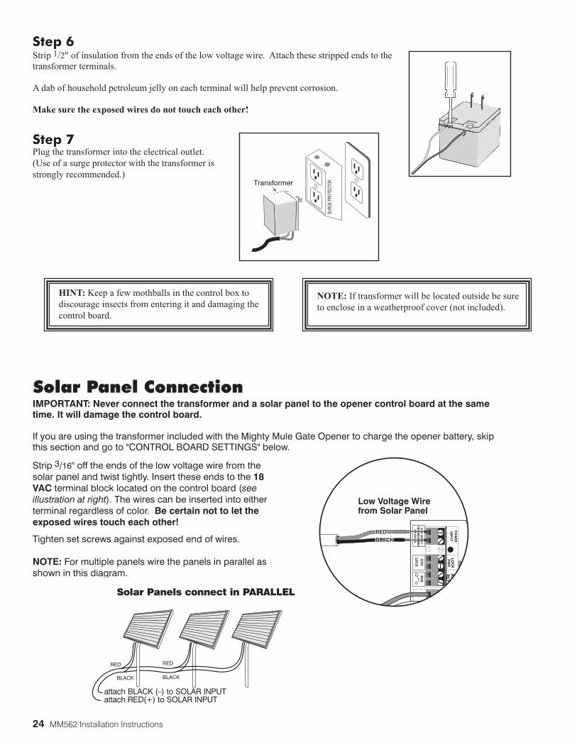
Step 7Plug the transformer into the electrical outlet.(Use of a surge protector with the transformer is strongly recommended.)
HINT: Keep a few mothballs in the control box to discourage insects from entering it and damaging the control board.
NOTE: If transformer will be located outside be sureto enclose in a weatherproof cover (not included).
Step 6Strip 1/2" of insulation from the ends of the low voltage wire. Attach these stripped ends to the transformer terminals.
A dab of household petroleum jelly on each terminal will help prevent corrosion.
Make sure the exposed wires do not touch each other!
SURG
E PR
OTEC
TORTransformer
IMPORTANT: Never connect the transformer and a solar panel to the opener control board at the same time. It will damage the control board.
If you are using the transformer included with the Mighty Mule Gate Opener to charge the opener battery, skip this section and go to "CONTROL BOARD SETTINGS" below.
Strip 3/16" off the ends of the low voltage wire from the solar panel and twist tightly. Insert these ends to the 18 VAC terminal block located on the control board (see illustration at right). The wires can be inserted into either terminal regardless of color. Be certain not to let the exposed wires touch each other!
Tighten set screws against exposed end of wires.
NOTE: For multiple panels wire the panels in parallel as shown in this diagram.
RED RED
BLACK BLACK
attach BLACK (–) to SOLAR INPUTattach RED(+) to SOLAR INPUT
Solar Panels connect in PARALLEL WHT
GRN
PO
WE
RIN
PU
TLO
CK
PW
RA
UX
RLY
CO
NT
RO
LO
UT
PU
TS
2N
D O
PE
RA
TOR
GTO
18
VO
LTTR
AN
SFOR
MER
OR
SOLA
R
GTO
LOC
K
AU
X
REDBLACK
REDBLACK
Low Voltage Wirefrom Solar Panel
Solar Panel Connection
MM562 Installation Instructions 25
1 2
3 4
ON
DIP
STATUS
LEARN RMT
LEARNMAST LIMIT
LEARNSLV LIMIT
S3
S4
S2
OFF
SOFT START OFFWARNING OFFOPEN PULLSLV OPEN DLY.MODE1 OFFMODE2 OFF
ONONPUSHSIMULT.ONON
120 MIN MAX
AUTO CLOSE TIME STALL FORCE
1 2
3 4
ON
DIP
STATUS
LEARN RMT
LEARNMAST LIMIT
LEARNSLV LIMIT
S3
S4
S2
OFF
SOFT START OFFWARNING OFFOPEN PULLSLV OPEN DLY.MODE1 OFFMODE2 OFF
ONONPUSHSIMULT.ONON
120 MIN MAX
AUTO CLOSE TIME STALL FORCE
1 2
3 4
ON
DIP
SOFT START OFFWARNING OFFOPEN PULLSLV OPEN DLY.MODE1 OFFMODE2 OFF
ONONPUSHSIMULT.ONON
120 MIN
ON
OFF1 O
N
DIP
23
4
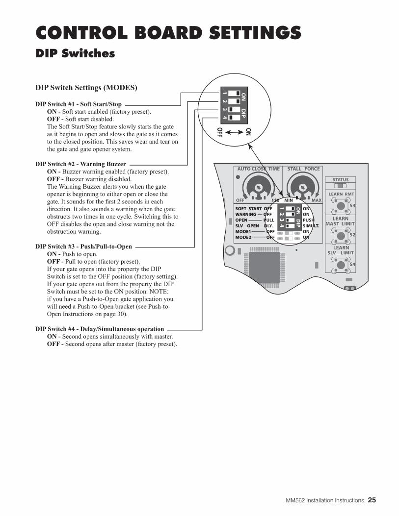
CONTROL BOARD SETTINGS DIP Switches
DIP Switch Settings (MODES)
DIP Switch #1 - Soft Start/Stop ON - Soft start enabled (factory preset). OFF - Soft start disabled. The Soft Start/Stop feature slowly starts the gate
as it begins to open and slows the gate as it comes to the closed position. This saves wear and tear on the gate and gate opener system.
DIP Switch #2 - Warning Buzzer ON - Buzzer warning enabled (factory preset). OFF - Buzzer warning disabled. The Warning Buzzer alerts you when the gate
opener is beginning to either open or close the gate. It sounds for the first 2 seconds in each direction. It also sounds a warning when the gate obstructs two times in one cycle. Switching this to OFF disables the open and close warning not the obstruction warning.
DIP Switch #3 - Push/Pull-to-Open ON - Push to open. OFF - Pull to open (factory preset). If your gate opens into the property the DIP
Switch is set to the OFF position (factory setting). If your gate opens out from the property the DIP Switch must be set to the ON position. NOTE: if you have a Push-to-Open gate application you will need a Push-to-Open bracket (see Push-to-Open Instructions on page 30).
DIP Switch #4 - Delay/Simultaneous operation ON - Second opens simultaneously with master. OFF - Second opens after master (factory preset).
26 MM562 Installation Instructions
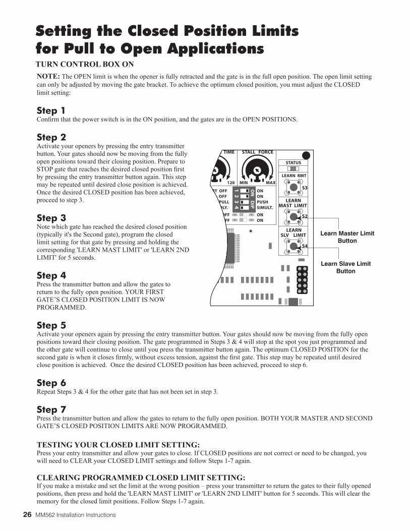
NOTE: The OPEN limit is when the opener is fully retracted and the gate is in the full open position. The open limit setting can only be adjusted by moving the gate bracket. To achieve the optimum closed position, you must adjust the CLOSED limit setting:
Step 1Confirm that the power switch is in the ON position, and the gates are in the OPEN POSITIONS.
Step 2Activate your openers by pressing the entry transmitter button. Your gates should now be moving from the fully open positions toward their closing position. Prepare to STOP gate that reaches the desired closed position first by pressing the entry transmitter button again. This step may be repeated until desired close position is achieved. Once the desired CLOSED position has been achieved, proceed to step 3.
Step 3Note which gate has reached the desired closed position (typically it's the Second gate), program the closed limit setting for that gate by pressing and holding the corresponding 'LEARN MAST LIMIT' or 'LEARN 2ND LIMIT' for 5 seconds.
Step 4Press the transmitter button and allow the gates to return to the fully open position. YOUR FIRST GATE’S CLOSED POSITION LIMIT IS NOW PROGRAMMED.
Step 5Activate your openers again by pressing the entry transmitter button. Your gates should now be moving from the fully open positions toward their closing position. The gate programmed in Steps 3 & 4 will stop at the spot you just programmed and the other gate will continue to close until you press the transmitter button again. The optimum CLOSED POSITION for the second gate is when it closes firmly, without excess tension, against the first gate. This step may be repeated until desired close position is achieved. Once the desired CLOSED position has been achieved, proceed to step 6.
Step 6Repeat Steps 3 & 4 for the other gate that has not been set in step 3.
Step 7Press the transmitter button and allow the gates to return to the fully open position. BOTH YOUR MASTER AND SECOND GATE’S CLOSED POSITION LIMITS ARE NOW PROGRAMMED.
TESTING YOUR CLOSED LIMIT SETTING:Press your entry transmitter and allow your gates to close. If CLOSED positions are not correct or need to be changed, you will need to CLEAR your CLOSED LIMIT settings and follow Steps 1-7 again.
CLEARING PROGRAMMED CLOSED LIMIT SETTING:If you make a mistake and set the limit at the wrong position – press your transmitter to return the gates to their fully opened positions, then press and hold the 'LEARN MAST LIMIT' or 'LEARN 2ND LIMIT' button for 5 seconds. This will clear the memory for the closed limit positions. Follow Steps 1-7 again.
Setting the Closed Position Limitsfor Pull to Open Applications
1 2
3 4
ON
D
IPSTATUS
LEARN RMT
LEARNMAST LIMIT
LEARNSLV LIMIT
S3
S4
S2
ART OFFG OFF PULL
EN DLY.
OFF OFF
ONONPUSHSIMULT.
ONON
120 MIN MAX
CLOSE TIME STALL FORCE
Learn Master LimitButton
Learn Slave LimitButton
TURN CONTROL BOX ON

MM562 Installation Instructions 27
Setting Your Personal Transmitter CodeAll GTO transmitters are set to a standard code at the factory and are ready to operate your GTO® Gate Opener®. For your safety and security, however, we strongly recommend that you replace the factory setting with your own personal code. Follow the directions below:
3. “Teach” the New Code to Control Board MemoryA. Press and hold transmitter button.B. Press and hold the LEARN RMT (Learn Remote) button
on the control board until the buzzer sounds.C. Release transmitter button. The new code is stored in control board memory.D. Release the LEARN RMT (Learn Remote) button.
Learn RemoteButton
1 2
3 4
ON
D
IP
STATUS
LEARN RMT
LEARNMAST LIMIT
LEARNSLV LIMIT
S3
S4
S2
ART OFFG OFF PULL
EN DLY.
OFF OFF
ONONPUSHSIMULT.
ONON
120 MIN MAX
CLOSE TIME STALL FORCE
2. Set the transmitter DIP SwitchesThere are nine (9) transmitter DIP switches; each can be placed in three different positions (+, 0, –). DO NOT set all the switches in the same position, such as all +, all 0, or all –. Once the DIP switches have been set to a personal code, replace front cover.
WARNING: No other adjustments should be made inside the transmitter.
1. Remove the Transmitter CoverOn the back of the transmitter use a small phillips head screw driver to remove the two screws on the sides of the visor clip and separate the front cover from the transmitter. With the front cover removed, the battery and the DIP switches will be exposed. To set a new code, use a small screwdriver to move the switches.
+0
ECE
1 2 3 4 5 6 7 8 9
1 2
3 4
5 6
7 8
9
ECE
A23S 12V
ALKALINE BATTERY
+0
–
LED
NOTE: For any additional transmitters you may have purchased, match the DIP switch settings and they will work with the transmitter you just programmed.
28 MM562 Installation Instructions
1 2
3 4
ON
OFF
SOFT START OFFWARNING OFFOPEN PULLSLV OPEN DLY.
MODE1 OFFMODE2 OFF
ONONPUSSIM
ONON
120 MIN
AUTO CLOSE TIME STALL FO1
2 3
4
ON
OFF
SOFT START OFFWARNING OFFOPEN PULLSLV OPEN DLY.
MODE1 OFFMODE2 OFF
ONONPUSSIM
ONON
120 MIN
O CLOSE TIME STALL FO
O
SM
TO O1
2
ON ON
ON
0 MIN MAX
E STALL FORCE
MIN MAX
STALL FORCE
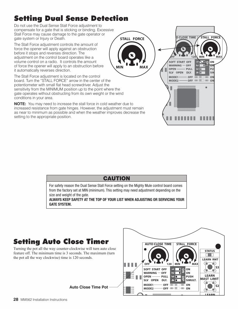
Setting Dual Sense Detection Do not use the Dual Sense Stall Force adjustment to compensate for a gate that is sticking or binding. Excessive Stall Force may cause damage to the gate operator or gate system or Injury or Death.
The Stall Force adjustment controls the amount of force the opener will apply against an obstruction before it stops and reverses direction. The adjustment on the control board operates like a volume control on a radio. It controls the amount of force the opener will apply to an obstruction before it automatically reverses direction.
The Stall Force adjustment is located on the control board. Turn the “STALL FORCE” arrow in the center of the potentiometer with small flat head screwdriver. Adjust the sensitivity from the MINIMUM position up to the point where the gate operates without obstructing from its own weight or the wind conditions in your area.
NOTE: You may need to increase the stall force in cold weather due to increased resistance from gate hinges. However, the adjustment must remain as near to minimum as possible and when the weather improves decrease the setting to the appropriate position.
For safety reason the Dual Sense Stall Force setting on the Mighty Mule control board comes from the factory set at MIN (minimum). This setting may need adjustment depending on the size and weight of the gate.ALWAYS KEEP SAFETY AT THE TOP OF YOUR LIST WHEN ADJUSTING OR SERVICING YOUR GATE SYSTEM.
CAUTION
Auto Close Time Pot
1 2
3 4
ON
D
IP
STATUS
LEARN RMT
LEARNMAST LIMIT
LEARN
S3
S2
OFF
SOFT START OFFWARNING OFFOPEN PULLSLV OPEN DLY.
MODE1 OFFMODE2 OFF
ONONPUSHSIMULT.
ONON
120 MIN MAX
AUTO CLOSE TIME STALL FORCESetting Auto Close TimerTurning the pot all the way counter-clockwise will turn auto close feature off. The minimum time is 3 seconds. The maximum (turn the pot all the way clockwise) time is 120 seconds.
MM562 Installation Instructions 29
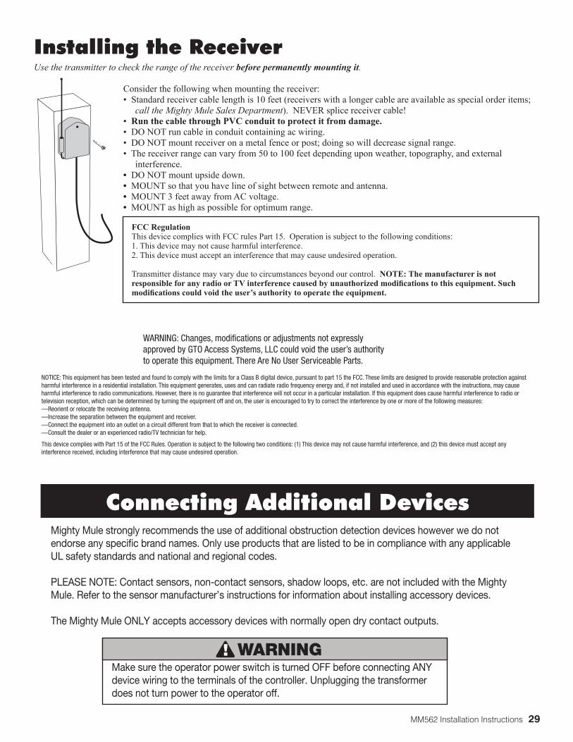
Installing the ReceiverUse the transmitter to check the range of the receiver before permanently mounting it.
Consider the following when mounting the receiver:• Standard receiver cable length is 10 feet (receivers with a longer cable are available as special order items; call the Mighty Mule Sales Department). NEVER splice receiver cable!• Run the cable through PVC conduit to protect it from damage. • DO NOT run cable in conduit containing ac wiring.• DO NOT mount receiver on a metal fence or post; doing so will decrease signal range.• The receiver range can vary from 50 to 100 feet depending upon weather, topography, and external interference.• DO NOT mount upside down.• MOUNT so that you have line of sight between remote and antenna.• MOUNT 3 feet away from AC voltage.• MOUNT as high as possible for optimum range.
FCC RegulationThis device complies with FCC rules Part 15. Operation is subject to the following conditions:1. This device may not cause harmful interference.2. This device must accept an interference that may cause undesired operation.
Transmitter distance may vary due to circumstances beyond our control. NOTE: The manufacturer is not responsible for any radio or TV interference caused by unauthorized modifications to this equipment. Such modifications could void the user’s authority to operate the equipment.
Mighty Mule strongly recommends the use of additional obstruction detection devices however we do not endorse any specific brand names. Only use products that are listed to be in compliance with any applicable UL safety standards and national and regional codes.
PLEASE NOTE: Contact sensors, non-contact sensors, shadow loops, etc. are not included with the Mighty Mule. Refer to the sensor manufacturer’s instructions for information about installing accessory devices.
The Mighty Mule ONLY accepts accessory devices with normally open dry contact outputs.
Make sure the operator power switch is turned OFF before connecting ANY device wiring to the terminals of the controller. Unplugging the transformer does not turn power to the operator off.
WARNING
WARNING: Changes, modifications or adjustments not expressly approved by GTO Access Systems, LLC could void the user’s authority to operate this equipment. There Are No User Serviceable Parts.
NOTICE: This equipment has been tested and found to comply with the limits for a Class B digital device, pursuant to part 15 the FCC. These limits are designed to provide reasonable protection against harmful interference in a residential installation. This equipment generates, uses and can radiate radio frequency energy and, if not installed and used in accordance with the instructions, may cause harmful interference to radio communications. However, there is no guarantee that interference will not occur in a particular installation. If this equipment does cause harmful interference to radio or television reception, which can be determined by turning the equipment off and on, the user is encouraged to try to correct the interference by one or more of the following measures:—Reorient or relocate the receiving antenna.—Increase the separation between the equipment and receiver.—Connect the equipment into an outlet on a circuit different from that to which the receiver is connected.—Consult the dealer or an experienced radio/TV technician for help.
This device complies with Part 15 of the FCC Rules. Operation is subject to the following two conditions: (1) This device may not cause harmful interference, and (2) this device must accept any interference received, including interference that may cause undesired operation.
Connecting Additional Devices
30 MM562 Installation Instructions
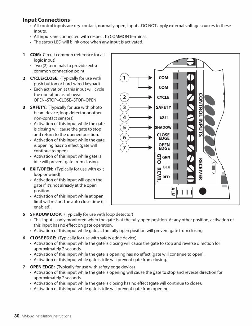
Input Connections • All control inputs are dry-contact, normally open, inputs. DO NOT apply external voltage sources to these
inputs. • All inputs are connected with respect to COMMON terminal. • The status LED will blink once when any input is activated.
1 COM: Circuit common (reference for all logic input)
• Two (2) terminals to provide extra common connection point.
2 CYCLE/CLOSE: (Typically for use with push button or hard-wired keypad)
• Each activation at this input will cycle the operation as follows:
OPEN–STOP–CLOSE–STOP–OPEN
3 SAFETY: (Typically for use with photo beam device, loop detector or other non-contact sensors)
• Activation of this input while the gate is closing will cause the gate to stop and return to the opened position.
• Activation of this input while the gate is opening has no effect (gate will continue to open).
• Activation of this input while gate is idle will prevent gate from closing.
4 EXIT/OPEN: (Typically for use with exit loop or wand)
• Activation of this input will open the gate if it’s not already at the open position
• Activation of this input while at open limit will restart the auto close time (if enabled).
5 SHADOW LOOP: (Typically for use with loop detector) • This input is only monitored when the gate is at the fully open position. At any other position, activation of
this input has no effect on gate operation. • Activation of this input while gate at the fully open position will prevent gate from closing.
6 CLOSE EDGE: (Typically for use with safety edge device) • Activation of this input while the gate is closing will cause the gate to stop and reverse direction for
approximately 2 seconds. • Activation of this input while the gate is opening has no effect (gate will continue to open). • Activation of this input while gate is idle will prevent gate from closing.
7 OPEN EDGE: (Typically for use with safety edge device) • Activation of this input while the gate is opening will cause the gate to stop and reverse direction for
approximately 2 seconds. • Activation of this input while the gate is closing has no effect (gate will continue to close). • Activation of this input while gate is idle will prevent gate from opening.
1
2
3
4
7
5
6
RE
CE
IVE
R
ALM
GTO
RC
VR
.
BLK
COM
GRN
BLK
RED
CYCLE
SAFETY
EXIT
SHADOW
OPENEDGE
COM
CO
NT
RO
L INP
UT
SCLOSEEDGE
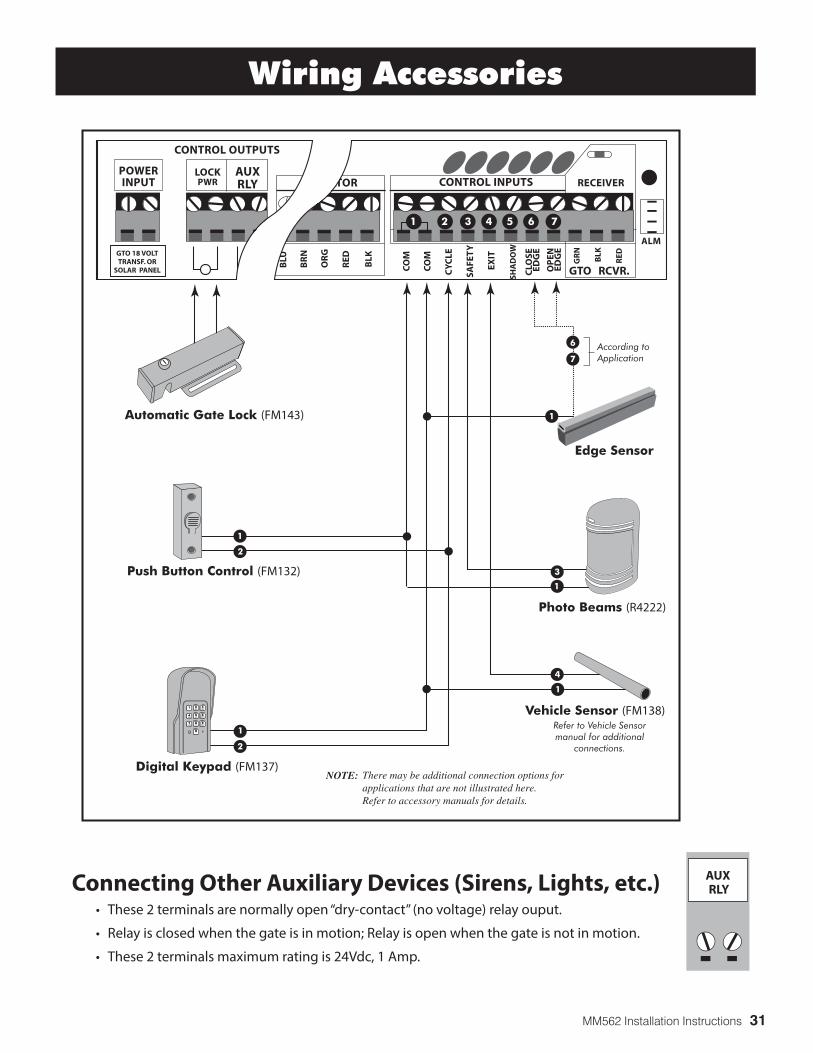
MM562 Installation Instructions 31
RECEIVER
ALM
GTO RCVR.
WH
T
BLU
BR
N
OR
G
RED
BLK
WH
T
BLU
BR
N
OR
G
RED BLK
GR
N
CO
M
GR
N
BLK
RED
CY
CLE
SAFE
TY
EXIT
SHA
DO
W
OP
ENED
GE
CO
M
MASTER OPERATOR2ND OPERATOR CONTROL INPUTS
CLO
SEED
GE
2 3 4 5 6 7
WH
T
BLU
BR
N
OR
G
RED
BLK
GR
N
WH
T
BLU
BR
N
OR
G
RED BLK
GR
N
CO
M
CY
CLE
CO
M
LOCKPWR
AUXRLY
POWERINPUT
CONTROL OUTPUTS
MASTER OPERATOR2ND OPERATOR CONTROL INPUTS
GTO 18 VOLTTRANSF. OR
SOLAR PANEL
1 2 3 4 5 6 71 2 3 4 5 6 7
Photo Beams (R4222)
Push Button Control (FM132)
Automatic Gate Lock (FM143)
According toApplication
Vehicle Sensor (FM138)Refer to Vehicle Sensormanual for additional
connections.
Edge Sensor
NOTE: There may be additional connection options for applications that are not illustrated here. Refer to accessory manuals for details.
2
1
1
3
1
1
Digital Keypad (FM137)
4
1
2
1 2ABC
3DEF
4GHI
5JKL
6MNO
7PRS
8TUV
9WXY
0
7
6
Connecting Other Auxiliary Devices (Sirens, Lights, etc.) • These 2 terminals are normally open “dry-contact” (no voltage) relay ouput.
• Relay is closed when the gate is in motion; Relay is open when the gate is not in motion.
• These 2 terminals maximum rating is 24Vdc, 1 Amp.
Wiring Accessories
RLYAUX
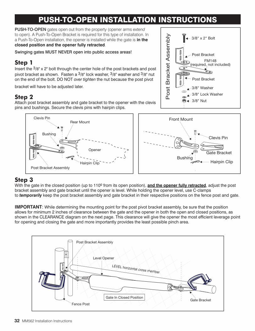
32 MM562 Installation Instructions
PUSH-TO-OPEN gates open out from the property (opener arms extend to open). A Push-To-Open Bracket is required for this type of installation. In a Push-To-Open installation, the opener is installed while the gate is in the closed position and the opener fully retracted.
Swinging gates MUST NEVER open into public access areas!
Step 1 Insert the 3/8" x 2" bolt through the center hole of the post brackets and post pivot bracket as shown. Fasten a 3/8" lock washer, 3/8" washer and 3/8" nut on the end of the bolt. DO NOT over tighten the nut because the post pivot
bracket will have to be adjusted later.
Step 2 Attach post bracket assembly and gate bracket to the opener with the clevis pins and bushings. Secure the clevis pins with hairpin clips.
Step 3 With the gate in the closed position (up to 110º from its open position), and the opener fully retracted, adjust the post bracket assembly and gate bracket until the opener is level. While holding the opener level, use C-clamps to temporarily keep the post bracket assembly and gate bracket in their respective positions on the fence post and gate.
IMPORTANT: While determining the mounting point for the post pivot bracket assembly, be sure that the position allows for minimum 2 inches of clearance between the gate and the opener in both the open and closed positions, as shown in the CLEARANCE diagram on the next page. This clearance will give the opener the most efficient leverage point for opening and closing the gate and more importantly provides the least possible pinch area.
3/8" x 2" Bolt
3/8" Nut
FM148(required, not included)
Post Bracket
Post Bracket
3/8" Lock Washer
Po
st
Bra
cket
Assem
bly
3/8" Washer
PUSH-TO-OPEN INSTALLATION INSTRUCTIONS
Level Opener
Fence Post
Gate In Closed Position
LEVEL horizontal cross member
Post Bracket Assembly
Gate Bracket
Clevis Pin
Hairpin ClipPost Bracket Assembly
Bushing
Rear Mount
Opener
Clevis Pin
Hairpin ClipBushing
Gate Bracket
Front Mount
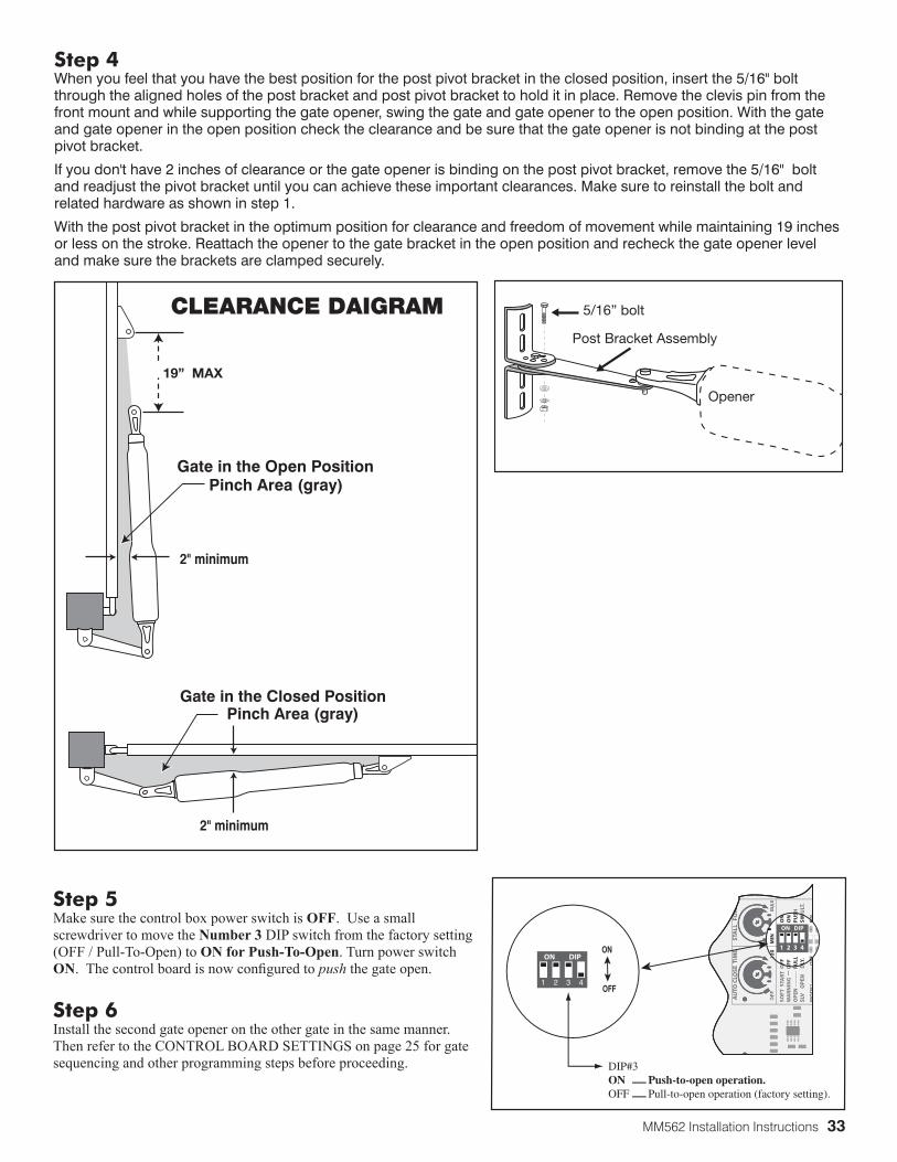
MM562 Installation Instructions 33
19” MAX
CLEARANCE DAIGRAM
Step 5Make sure the control box power switch is OFF. Use a small screwdriver to move the Number 3 DIP switch from the factory setting (OFF / Pull-To-Open) to ON for Push-To-Open. Turn power switch ON. The control board is now configured to push the gate open.
Step 6Install the second gate opener on the other gate in the same manner. Then refer to the CONTROL BOARD SETTINGS on page 25 for gate sequencing and other programming steps before proceeding. DIP#3
ON Push-to-open operation.OFF Pull-to-open operation (factory setting).
ON
OFF1
ON DIP
2 3 4
1 2 3 4
ON
OFF
SO
FT S
TAR
T O
FFW
AR
NIN
G
O
FFO
PE
N
PU
LLS
LV
OP
EN
D
LY.
MO
DE
1O
FF
ON
ON
PU
SH
SIM
ULT
.
ON
12
0M
INM
AX
AU
TO C
LOSE
TIM
E ST
ALL
FO
RC
E
1 2 3 4
ON
OFF
SO
FT S
TAR
T O
FFW
AR
NIN
G
O
FFO
PE
N
PU
LLS
LV
OP
EN
D
LY.
MO
DE
1O
FF
ON
ON
PU
SH
SIM
ULT
.
ON
12
0M
INM
AX
AU
TO C
LOSE
TIM
E ST
ALL
FO
RC
1 2 3 4
ON DIP
OFF
OFF
PU
LLD
LY.
OFF
OFF
ON
ON
PU
SS
IMU
ON
ON
12
0M
IN
Step 4 When you feel that you have the best position for the post pivot bracket in the closed position, insert the 5/16" bolt through the aligned holes of the post bracket and post pivot bracket to hold it in place. Remove the clevis pin from the front mount and while supporting the gate opener, swing the gate and gate opener to the open position. With the gate and gate opener in the open position check the clearance and be sure that the gate opener is not binding at the post pivot bracket.
If you don't have 2 inches of clearance or the gate opener is binding on the post pivot bracket, remove the 5/16" bolt and readjust the pivot bracket until you can achieve these important clearances. Make sure to reinstall the bolt and related hardware as shown in step 1.
With the post pivot bracket in the optimum position for clearance and freedom of movement while maintaining 19 inches or less on the stroke. Reattach the opener to the gate bracket in the open position and recheck the gate opener level and make sure the brackets are clamped securely.
5/16” bolt
Post Bracket Assembly
Opener
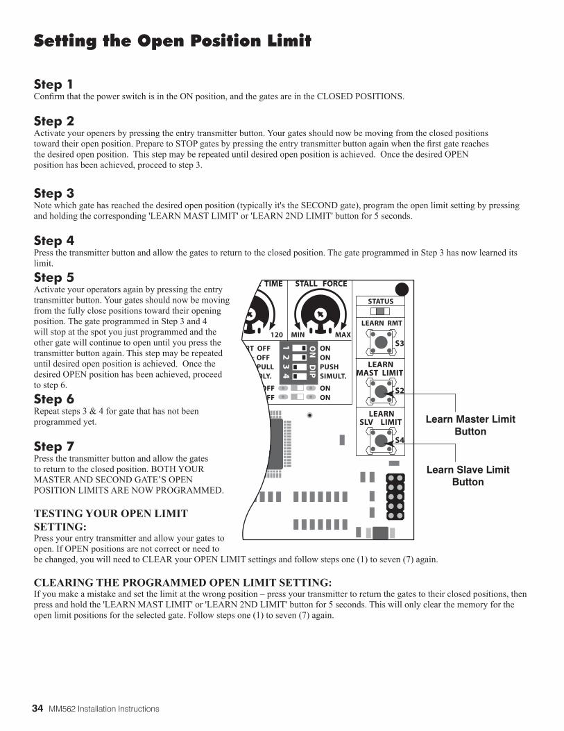
34 MM562 Installation Instructions
Step 3Note which gate has reached the desired open position (typically it's the SECOND gate), program the open limit setting by pressing and holding the corresponding 'LEARN MAST LIMIT' or 'LEARN 2ND LIMIT' button for 5 seconds.
Step 4Press the transmitter button and allow the gates to return to the closed position. The gate programmed in Step 3 has now learned its limit.
Step 5Activate your operators again by pressing the entry transmitter button. Your gates should now be moving from the fully close positions toward their opening position. The gate programmed in Step 3 and 4 will stop at the spot you just programmed and the other gate will continue to open until you press the transmitter button again. This step may be repeated until desired open position is achieved. Once the desired OPEN position has been achieved, proceed to step 6.
Step 6Repeat steps 3 & 4 for gate that has not been programmed yet.
Step 7Press the transmitter button and allow the gates to return to the closed position. BOTH YOUR MASTER AND SECOND GATE’S OPEN POSITION LIMITS ARE NOW PROGRAMMED.
TESTING YOUR OPEN LIMIT SETTING:Press your entry transmitter and allow your gates to open. If OPEN positions are not correct or need to be changed, you will need to CLEAR your OPEN LIMIT settings and follow steps one (1) to seven (7) again.
CLEARING THE PROGRAMMED OPEN LIMIT SETTING:If you make a mistake and set the limit at the wrong position – press your transmitter to return the gates to their closed positions, then press and hold the 'LEARN MAST LIMIT' or 'LEARN 2ND LIMIT' button for 5 seconds. This will only clear the memory for the open limit positions for the selected gate. Follow steps one (1) to seven (7) again.
1 2
3 4
ON
D
IP
STATUS
LEARN RMT
LEARNMAST LIMIT
LEARNSLV LIMIT
S3
S4
S2
ART OFFG OFF PULL
EN DLY.
OFF OFF
ONONPUSHSIMULT.
ONON
120 MIN MAX
CLOSE TIME STALL FORCE
Learn Master LimitButton
Learn Slave LimitButton
Setting the Open Position Limit
Step 1Confirm that the power switch is in the ON position, and the gates are in the CLOSED POSITIONS.
Step 2Activate your openers by pressing the entry transmitter button. Your gates should now be moving from the closed positions toward their open position. Prepare to STOP gates by pressing the entry transmitter button again when the first gate reaches the desired open position. This step may be repeated until desired open position is achieved. Once the desired OPEN position has been achieved, proceed to step 3.

MM562 Installation Instructions 35
If your gate opener does not function properly after it is installed, use this guide before calling the GTO Service Department.
Audible FeedbackIndication Possible Diagnosis Check1 short beep upon activation Blown Fuse
Low or Bad BatteryLoose Battery Connection
• Fuse• Battery Under Load• Battery Harness Connections
A series of beeps that stop and do not repeat after power-up
Circuit Board Powered Up & Ready
• Normal Operation
Continuous Uninterrupted Alarm
Circuit Board Senses an Obstruction
• Path of Gate• Gate for Level and Plumb• Stall Force Adjustment• For diagnostic purposes, temporarily disconnect the
external obstruction detection devices• Rev Counter
1 beep with 10 seconds off Low Battery Condition • Fuses• Battery Harness Connections• Battery Under Load
1 beep then 2 beeps, then pause and repeats
Master Motor Terminals Shorted
• Connections to Master Inputs • Master Arm Power Cable• Motor• Circuit Board
1 beep then 3 beeps, then pause and repeats
Second Motor Terminals Shorted
• Connections to Second Inputs• Second Arm Power Cable• Motor• Circuit Board
1 beep with 2 seconds, then pause and repeats
Master Arm Limit Switch Error
• Connections to Master Inputs• Master Arm Power Cable
2 beeps with 2 seconds, then pause and repeats
Second Arm Limit Switch Error
• Connections to Second Inputs• Second Arm Power Cable
3 beeps with 2 seconds, then pause and repeats
Master Arm Rev Counter Error
• Connections to Master Inputs• Master Arm Power Cable• Rev Counter
4 beeps with 2 seconds, then pause and repeats
Second Arm Rev Counter Error
• Connections to Second Inputs• Second Arm Power Cable• Rev Counter
Troubleshooting Guide
VOLTAGE READINGS18 Vac Transformer .....................................................................................18.0 to 22.0 Vac, 2200 mA5 W Solar panel (single) ............................................................................18.0 to 22.0 Vdc, 300 mA* measure voltage at panel and control box in full sun; this will increase by approximately 300mA for each additional solar panel.
Two 12 V, 7 amp hour Batteries .............................................................12.5 to 13.5 Vdc 7.0 Ah*measure voltage at battery terminals with battery disconnected from circuit board
Charging circuit ..........................................................................................13.3 to 14.8 Vdc*measure voltage at battery terminals with battery connected to circuit board and GREEN "POWER IN" LED is ON.

36 MM562 Installation Instructions
Visual FeedbackIndication Possible Diagnosis Check
Status (clear) 1 blink Cycle Terminal ShortedDisconnect the push button, keypad, intercom keypad, or any other accessory wired to this terminal. Try the remote. If the remote works, then the problem is the accessory.
Status (clear) 2 blinks Safety Terminal Shorted
Disconnect the loop detector, photo beam, or any other accessory wired to this terminal. Try the remote. If the remote works, the problem is the accessory.
Status (clear) 3 blinks Exit Terminal Shorted Disconnect exit wand, loop detector, photo beam, Knox box, or any other accessory wired to this terminal. Try remote. If the remote works, the problem is the accessory.
Status (clear) 4 blinks Shadow Terminal Shorted
Disconnect the loop detector, photo beam, or any other accessory wired to this terminal. Try remote. If the remote works, the problem is the accessory.
Status (clear) 5 blinks Close Edge Terminal Shorted
Disconnect the edge sensor, photo beam, or any other accessory wired to this terminal. Try the remote. If the remote works, the problem is the accessory.
Status (clear) 6 blinks Open Edge Terminal Shorted
Disconnect edge sensor, photo beam, or any other accessory wired to this terminal. Try the remote. If the remote works, the problem is the accessory.
RF (yellow) Flickers Receiving 318 MHz RF
Normal operation when remote or wireless keypad is used.
RF (yellow) does not flash when remote is pressed
No 318 MHz RF Received
• Battery in Remote• Program Remote• Antenna Receiver Connections• Antenna Receiver
Power (green) ON AC or Solar Power Present
Normal Operation
Power (green) OFF No AC or Solar Power Transformer:• Breaker or GFI• Power at AC outlet.• Output of Transformer.• Voltage on wire at 18 VAC Input
Solar:• Weather• Solar Panel Placement• Output of Solar Panel• Voltage on wire at Solar Input
Charge (red) ON and FLASH
Unit in fast, soak or float charge
Battery voltage increasing slowly or stead at aprox 13.8 -14.1. Normal condition.
Charge (red) OFF Battery Not Being Charged
AC powerTransformerSolar Panel Charging Circuit

MM562 Installation Instructions 37
15FUSE
BATT+
BATT-
1 2
3 4
ON
STATUS
LEARN RMT
RECEIVER
LEARNMAST LIMIT
LEARN2ND LIMIT
S3
S4
ALM
S2
OFF
SOFT START OFFWARNING OFFOPEN PULL2ND OPEN DLY.
MODE1 OFFMODE2 OFF
ONONPUSHSIMULT.
ONON
120 MIN MAX
CHARGING
POWER IN
GTO RCVR.
WH
T
BLU
BR
N
OR
G
RED
BLK
GR
N
WH
T
BLU
BR
N
OR
G
RED BLK
GR
N
CO
M
GR
N
BLK
RED
CY
CLE
SAFE
TY
EXIT
SHA
DO
W
OP
ENED
GE
CO
M
LOCKPWR
AUXRLY
POWERINPUT
CONTROL OUTPUTS
MASTER OPERATOR2ND OPERATOR CONTROL INPUTS
AUTO CLOSE TIME STALL FORCE
CLO
SEED
GEGTO 18 VOLT
TRANSF. ORSOLAR PANEL
1 2 3 4 5 6 7
DIAGPORT
CHARGING
POWER IN
RED LED
GREEN LED
Battery/Power Troubleshooting
POWER IN LED CHARGING LEDON Steady ON Battery ChargingON Blinking Battery Fully ChargedON OFF Test charging circuit, check batteryOFF OFF No AC/Solar Power, check batteryOFF Blinking Check battery, incoming AC transformer or solarOFF Steady ON Test charging circuit and check incoming AC trans-
former or solar and check battery
Monthly, test the obstruction and entrapment protection systems.Monthly, service the gate operator (make sure the power switch is OFF). Clean extended operator arm with a soft, dry clean cloth. After cleaning, apply a high quality silicon spray to a soft dry cloth and wipe the push/pull tube. DO NOT directly spray the tube! On all gates weighing 250 lb. or more, routinely grease the ball bearing hinges at least 4 times a year; more frequently if the gates are near a coastal area.Monthly, turn off the power switch and disconnect the Mighty Mule and move the gate to make sure the gate is moving freely without sticking or binding. Lubricate the hinges or repair the gate as required before reattaching the Mighty Mule.Monthly, check the gate system for potentially entrapments from new landscaping or construction. Eliminate or guard as required.Monthly, check that the warning signs are mounted on each side of the gate and clearly visible. Replace the signs if they are missing or damaged.Replace batteries every 2-3 years and properly recycle old batteries.
MAINTENANCE

38 MM562 Installation Instructions
If your Gate Operator is not operating properly, please follow the steps below:
1. First use the procedures found in the Troubleshooting Guide (see page 25).
2. Use the 24/7 Troubleshooting Wizard at http://support.gtoinc.com.
3. If you are unable to solve the problem, call the GTO Service Department at (800) 543-1236, or (850) 575-4144. Refer to the serial number (located on the right side of the control box) and date of purchase when calling for assistance.
4. If repair or replacement of your gate operator is necessary, the Service Department will assign a Return Goods Authorization (RGA) number to you.
5. Securely pack the component(s) authorized for return to the factory. Include a copy of your sales receipt for the purchase of the product(s). Write the RGA number issued to you on the outside of the package in LARGE BOLD PRINT.
Ship the package(s) freight prepaid to: GTO, 3121 Hartsfield Road, Tallahassee, Florida, USA 32303.
NOTE: Products returned to GTO without a Return Goods Authorization (RGA) number in LARGE BOLD PRINT on the outside of the package WILL NOT be accepted. Also, items returned to GTO freight collect WILL NOT be accepted.
Repair Service
GTO Technical Service and Installation Assistance8:00am–7:00pm • Monday–Friday (EST)
Toll Free Support: 800-543-1236 • Local Support: 850-575-4144 • Fax: 850-575-8950
24/7 Troubleshooting Wizard: http://support.gtoinc.com

MM562 Installation Instructions 39
Accessories
POWERING ACCESSORIESLow Voltage Wire [RB509] The 16 gauge, stranded, dual conductor low voltage Wire is for connecting the AC powered transformer, solar panel or wired accessories to the system’s control board. This specially designed wire is UV treated, PVC coated, and ready for direct burial.
Solar Panel Kits [FM121/FM123]If your gate operator is more than 1000 ft. away from an AC power outlet, you can choose to maintain the battery charge with the GTO Solar Panel Kit.
• 10 Watt Solar Panel Charging Kit [FM123]
• 5 Watt Solar Panel Charging Kit [FM121]
Additional/Replacement Battery [FM150]For additional battery power or replacement.
“FROM VEHICLE” ENTRY AND EXIT ACCESSORIESTransmitters [FM135/FM134]Purchase an additional transmitter for each vehicle in your family. The Two-Button Transmitter can be programmed to operate both your gate operator and a garage door opener using the Universal Receiver. Or it can be programmed to open two gate operator systems.
• Single Button Transmitter [FM135]
• Dual Button Transmitter [FM134]
Universal Receiver [RB709U-NB]The Universal Antenna Receiver gives you the ability to use one remote to activate your gate operator and your garage door opener. Connects to any brand garage door opener. Up to 100 ft. range. This receiver only uses Mighty Mule transmitters.
Digital Keypad [FM137]Allow friends access to your property using an identification code that you provide. Program up to 25 entry codes for added security. Powered by three “AA” batteries (not included).
Please visit www.mightymule.com for photos and detailed descriptions of accessories. Or call 1-800-543-4283.
1 2ABC
3DEF
4GHI
5JKL
6MNO
7PRS
8TUV
9WXY
0
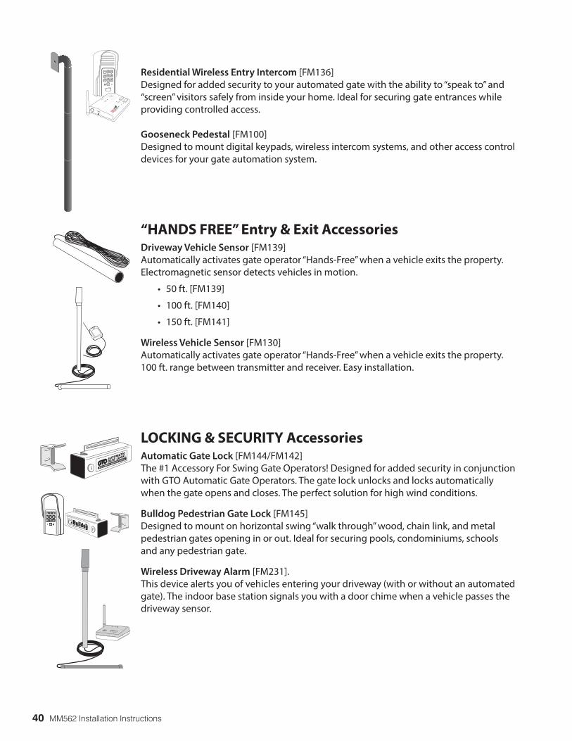
40 MM562 Installation Instructions
Residential Wireless Entry Intercom [FM136]Designed for added security to your automated gate with the ability to “speak to” and “screen” visitors safely from inside your home. Ideal for securing gate entrances while providing controlled access.
Gooseneck Pedestal [FM100]Designed to mount digital keypads, wireless intercom systems, and other access control devices for your gate automation system.
“HANDS FREE” Entry & Exit AccessoriesDriveway Vehicle Sensor [FM139]Automatically activates gate operator “Hands-Free” when a vehicle exits the property. Electromagnetic sensor detects vehicles in motion.
• 50 ft. [FM139]
• 100 ft. [FM140]
• 150 ft. [FM141]
Wireless Vehicle Sensor [FM130]Automatically activates gate operator “Hands-Free” when a vehicle exits the property. 100 ft. range between transmitter and receiver. Easy installation.
LOCKING & SECURITY AccessoriesAutomatic Gate Lock [FM144/FM142]The #1 Accessory For Swing Gate Operators! Designed for added security in conjunction with GTO Automatic Gate Operators. The gate lock unlocks and locks automatically when the gate opens and closes. The perfect solution for high wind conditions.
Bulldog Pedestrian Gate Lock [FM145]Designed to mount on horizontal swing “walk through” wood, chain link, and metal pedestrian gates opening in or out. Ideal for securing pools, condominiums, schools and any pedestrian gate.
Wireless Driveway Alarm [FM231].This device alerts you of vehicles entering your driveway (with or without an automated gate). The indoor base station signals you with a door chime when a vehicle passes the driveway sensor.
AUTOMATIC
GATE LOCK ®
ELECTRONIC SECURITY LOCK
, Inc.SECURITY GATE LOCK
®
2ABC
3DEF
5JKL
6MNO
8TUV
9WXY
0
1
4GHI
7PRS
POWER
Keypad
Batt Low
Grant
Permiss
ion
Answer
DV 9VAC
CESS
CONTR
OL
SYST
EMS
1-80
0-54
3-42
83

MM562 Installation Instructions 41
If you have a question about any special order item, just call 1-800-543-GATE!
The contents of all material available on this installation manual are copyrighted by GTO Access Systems, LLC (“GTO”), unless otherwise indicated. All rights are reserved by GTO, and content may not be reproduced, downloaded, disseminated, published, or transferred in any form or by any means, except with the prior, written permission of GTO. Any reprinting of GTO publications is by permission only. Copyright infringement is a violation of federal law.
Mighty Mule, E-Z Gate, GTO, Dual Sense Technology, Linear PRO Access, are registered trademarks of GTO Access Systems, LLC America’s DIY
Automatic Gate Openers is a trademark of GTO and are the exclusive property of GTO Access Systems, LLC. All rights are reserved by GTO, and these marks may not be used, in any for without the prior, written permission of GTO.
ADDITIONAL AccessoriesPhoto Beams [R4222]Primary “through beam” photo beam device. Provides “non-contact” obstruction protection.
Pin Lock [FM345]Use as a substitute for the clevis pin at the front mount of the gate opener to prevent theft of the operator.
• Pin Lock 10-pack: ten Pin Locks keyed alike [FM345KA].
Push Button Control [RB101]Wire this unlit push button directly to your gate operator for simple open/close/stop operation from up to 1000 ft. away. Use 16 gauge low-voltage wire.
Replacement Transformer [RB570]Standard 18 volt, 2200 mA AC transformer included with the gate operator to maintain battery charge.
HARDWARE AccessoriesPush To Open Brackets [FM148]Required when the gate operator must push a gate open (arm extends to open), such as away from a sloping driveway or where space prevents gate from opening into the property (pull to open). Order two brackets for a dual swing gate installation.

Gate Operator Installation Checklist
1. The gate has been checked to make sure it is level and moves freely in both directions.
2. Potential pinch areas have been guarded so as to be inaccessible OR have sensing edges and/or photo beam obstruction detection devices installed.
3. The installer has installed one or more contact or non-contact obstruction sensing devices, if required for this installation.
4. If pedestrian traffic is expected, a separate pedestrian gate has been installed, a minimum of seven feet from the gate systems. All pedestrian traffic must use the pedestrian gate.
5. Warning signs have been installed on each side of the gate in highly visible locations. These signs must remain at all times.
6. There are no controls installed on the gate operator, or within 10 feet of the gate.
7. The Dual Sense Technology feature has been properly adjusted and tested to make sure that the gate stops and reverses a short distance with minimal resistance applied.
8. Reviewed and understand all of the operational functions, obstruction sensing devices, warning beeper and reset, etc.
9. Review and understand the proper use of the operator’s manual disconnect feature. The manual disconnect must never be used while the gate is in motion. The power switch must be turned off before using the manual disconnect and disengaging the operator.
10. Reviewed all safety instructions, and keep the safety instructions and owner’s information sheets for reference.
11. Review and understand the maintenance schedule for both the gate and the gate operator.
For sales call toll free:
1-800-543-4283The Sales Department is open Monday – Friday 8:00 A.M. – 5:00 P.M. (Eastern Time)
For technical service Call toll free:1-800-543-1236
The Technical Service Department is open Monday – Friday 8:00 A.M. – 7:00 P.M. (Eastern Time)
3121 Hartsfield Road • Tallahassee, Florida, USA 32303www.mightymule.com