Embed Size (px)
Citation preview
INSTALLATION MANUAL
IOM-WR-SmartTrac 1340 2 of 16
This manual only covers installation of Watts Radiant’s SmartTrac™.
This is not a design manual. For design assistance, we encourage
you to contact us or our representatives for a design analysis
using RadiantWorks® or LoopCAD® Professional system design
software.
Before designing or installing a radiant heating or cooling system,
you should always consult with local, experienced design and
installation professionals to ensure compliance with local building
practices, climate conditions, state and local building codes, and
past customs.
Read Manual and all product labels BEFORE
using this product and follow all safety and
use information. Failure to do so could result in
personal injury or property damage.
•
To avoid serious personal injury or property damage:
Do not use unless you know the safe and proper operation
of equipment required for installation.
It is the installers responsibility to ensure that this product
is safely installed according to all applicable codes and
standards.
Keep this Manual available for easy access by all users.
Replacement Manuals are available at WattsRadiant.com
•
•
•
Introduction ......................................................................................................................... 3
SmartTrac™ Properties.......................................................................................................... 3
MDF Technical Data .............................................................................................................. 3
Features & Benefits of SmartTrac™ .............................................................................. 3
Design & Performance ..................................................................................................... 4
Heat Loss Analysis and System Design....................................................................... 3
R-Value of Floor Assemblies ............................................................................................. 3
System Output ......................................................................................................................... 3
Understanding the Product ........................................................................................... 5
Tubing & Tube Lengths .................................................................................................... 5
Pressure Drop Charts ........................................................................................................... 5
Preparing for Installation ................................................................................................ 6
Estimating the required tubing ...................................................................................... 6
Estimating the required number of panels ............................................................. 6
General floor surface requirements ............................................................................. 6
Wood subfloor requirements .......................................................................................... 6
Installation ............................................................................................................................. 6
Equipment required for installation over a wood subfloor ............................ 6
Installation overview............................................................................................................. 7
Layout ........................................................................................................................................... 7
Creating custom paths ........................................................................................................ 7
Manifold detail ......................................................................................................................... 8
Attaching SmartTrac™ to a subfloor ........................................................................... 8
Installing SmartTrac™ on walls or ceilings ............................................................... 9
Installing SmartTrac™ over concrete ............................................................................ 9
Installing tubing in the grooves ..................................................................................... 9
Pressure testing ....................................................................................................................... 9
Flooring Installation ........................................................................................................10
Installing SmartTrac™ Over Concrete ....................................................................... 12
Appendix A - R-Value of Typical Flooring Materials ........................................... 13
Example panel layout for 5 circuit system .............................................................14
Warranty ...............................................................................................................................16
Table of Contents
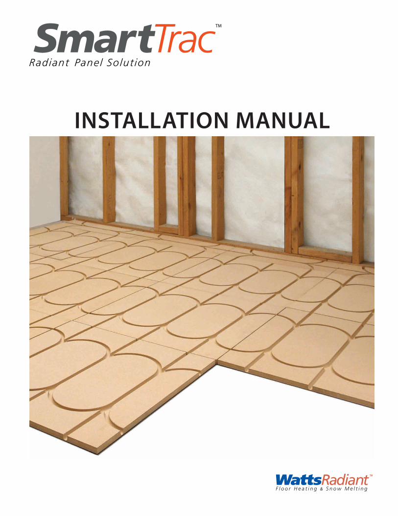
An Introduction to Radiant, the Smart Way This manual contains information related to radiant floor installations
using the SmartTrac™ Radiant Panel Solution. For design informa-
tion, please consult Watts Radiant’s RadiantWorks® or LoopCAD®
Professional design software.
Many of the accessory items used with SmartTrac™ are mentioned
in this manual. New tools and accessory items are added to the
Watts Radiant product offering on a regular basis. Please refer to
the Watts Radiant product catalog for current product information.
Additional product information may also be found at our web site
www.wattsradiant.com.
Watts Radiant offers a wide range of support options, from local whole-
salers and representatives to our factory-direct toll-free number.
When you select Watts Radiant, your choice comes with an entire
support team.
Understanding Safety Information
This is a safety-alert symbol. The safety alert symbol
is shown alone or used with a signal word (WARNING
or CAUTION), a pictorial and/or a safety message to
identify hazards.
When you see this symbol alone or with a signal word
on your equipment or in this Manual, be alert to the
potential for death or serious personal injury.
This symbol identifies hazards which, if not avoided,
could result in death or serious injury.
This symbol identifies hazards which, if not avoided,
could result in minor or moderate injury.
This symbol identifies practices, actions, or failure
to act which could result in property damage or
damage to the equipment.
3 of 16 © 2013 Watts Radiant
The SmartTrac™ Radiant Panel is non-structural and designed specifically
for subfloor, ceiling and wall applications. It is made of high recycled
content MDF. The dense board spreads the heat evenly and quickly
from the hydronic tubing that snaps easily into the channel.
SmartTrac™ heats rapidly and is easy to control with setback thermostats
for maximum energy efficiency. It contains just enough thermal mass
to be effective, but not so much that it is difficult to control. No other
product offers this combination of performance, ease of installation,
cost-effectiveness and ecologically responsible construction.
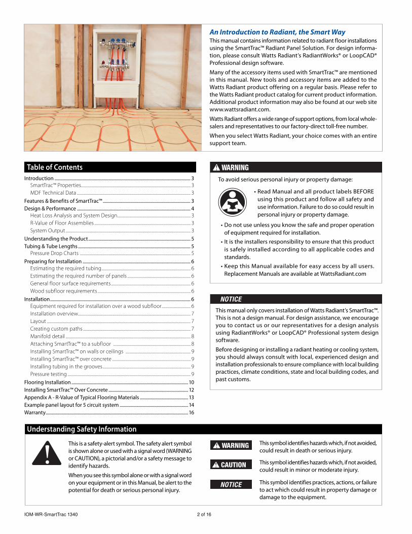
SmartTrac™ Properties
Dimensions: 24" x 24" x 5/8" (610 mm x 610 mm x 16 mm)
Standard
Panel Weight:
8.95 lbs (4.06 kg)
Utility Panel
Weight:
8.65 lbs (3.92 kg)
Tube Spacing: 8" (203 mm) O.C.
MDF Board: Awarded CARB ULEF Exemption. Products meet CARB
ATCM 93120 Phase 2 emission requirements. Meets
physical proper ties of ANSI A208.2-2009 Grade 130
Hydronic radiant heating is the most comfortable and efficient way
to heat your home or building, with numerous construction benefits
and unsurpassed flexibility in zoning. SmartTrac™ is designed for the
application of hydronic radiant tubing over a variety of construction
types. It may be used in new construction and is also advantageous
in the growing retrofit market. While only adding 5/8" (16 mm) to
the existing floor height, SmartTrac™ provides a superior performing
radiant heating or cooling system.
Installation FriendlySmartTrac™ has all the intelligence you need built into it so that the
vast majority of installations can be quickly accomplished using
only the Standard panel. For more complex installations, the Utility
panel can be used.
Construction FriendlySmartTrac™ avoids joist upsizing, double plating and hardwood
nailing strips associated with gypsum-based concrete radiant heating
systems. Also, SmartTrac™ eliminates substantial drying costs required
by moisture-laden concrete and gypsum-based cement. Time is
money. SmartTrac™ eliminates scheduling and curing delays.
Introduction
Features & Benefits of SmartTrac™
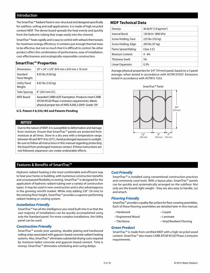
MDF Technical Data
Density: 46 lb/ft3 (7.4 kg/mm3)
Internal Bond: 130 lb/in2 (896 kPa)
Screw Holding, Face: 225 lbs (102 kg)
Screw Holding, Edge: 200 lbs (91 kg)
Flame Spread Rating: Class 3 (C)
Moisture Content: 4 - 6%
Thickness Swell: 5%
Linear Expansion: 0.3%
Average physical properties for 3/4" (19 mm) panel, based on a 5 panel
average, when tested in accordance with ASTM D1037. Emissions
tested in accordance with ASTM E-1333.
Cost FriendlySmartTrac™ is installed using conventional construction practices
and commonly used tools. With a layout plan, SmartTrac™ panels
can be quickly and systematically arranged on the subfloor. Not
only are the boards light weight - they are also easy to handle, cut
and attach.
Flooring FriendlySmartTrac™ provides a quality flat surface for floor covering assemblies.
Each of these flooring assemblies are detailed later in this manual.
Hardwood
Engineered Wood
Tile/Stone
•
•
•
Carpet
Laminate
Vinyl/Resilient Flooring
•
•
•
Green ProductSmartTrac™ is made from certified MDF with a high recycled wood
content. SmartTrac™ also meets CARB ATCM 93120 Phase 2 emission
requirements.
12"
24"(610 mm)
(102 mm)(203 mm)(305 mm)8" 4"
SmartTrac™ Panel
Due to the nature of MDF, it is susceptible to deformation and damage
from moisture. Ensure that SmartTrac™ panels are protected from
moisture at all times. Store in a dry area with a temperature range
between 40 and 90°F (4 to 32°C). Avoid prolonged exposure to sunlight.
Be sure to follow all instructions in this manual regarding protecting
the board from prolonged moisture contact. If these instructions are
not followed, expansion can create undesirable effects.
U.S. Patent # 6,533,185 and Patents Pending
IOM-WR-SmartTrac 1340 4 of 16
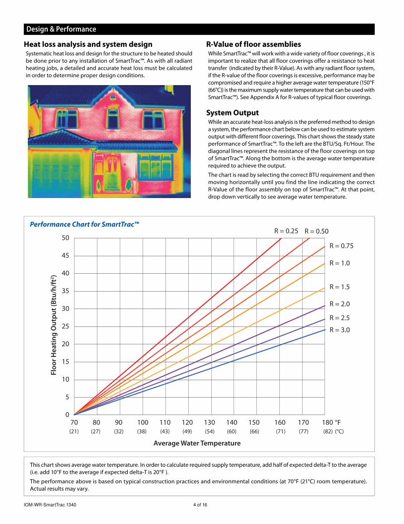
Heat loss analysis and system designSystematic heat loss and design for the structure to be heated should
be done prior to any installation of SmartTrac™. As with all radiant
heating jobs, a detailed and accurate heat loss must be calculated
in order to determine proper design conditions.
Design & Performance
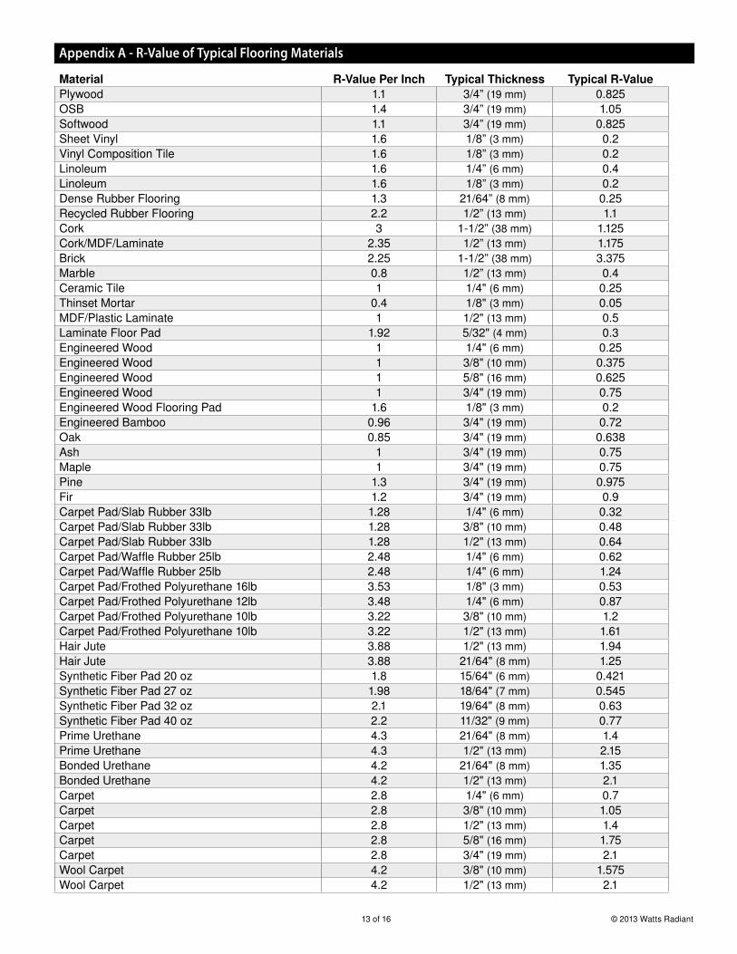
R-Value of floor assembliesWhile SmartTrac™ will work with a wide variety of floor coverings , it is
important to realize that all floor coverings offer a resistance to heat
transfer (indicated by their R-Value). As with any radiant floor system,
if the R-value of the floor coverings is excessive, performance may be
compromised and require a higher average water temperature (150°F
(66°C)) is the maximum supply water temperature that can be used with
SmartTrac™). See Appendix A for R-values of typical floor coverings.
System OutputWhile an accurate heat-loss analysis is the preferred method to design
a system, the performance chart below can be used to estimate system
output with different floor coverings. This chart shows the steady state
performance of SmartTrac™. To the left are the BTU/Sq. Ft/Hour. The
diagonal lines represent the resistance of the floor coverings on top
of SmartTrac™. Along the bottom is the average water temperature
required to achieve the output.
The chart is read by selecting the correct BTU requirement and then
moving horizontally until you find the line indicating the correct
R-Value of the floor assembly on top of SmartTrac™. At that point,
drop down vertically to see average water temperature.
Flo
or
He
ati
ng
Ou
tpu
t (B
tu/h
/ft2
)
Average Water Temperature
R = 0.75
R = 0.25 R = 0.50
R = 1.0
R = 1.5
R = 2.0
R = 3.0
50
45
40
35
30
25
20
15
10
5
070 80 90 100 110 120 130 140 150 160 170 180(21) (27) (32) (38) (43) (49) (54) (60) (66) (71) (77) (82)
R = 2.5
°F(°C)
Performance Chart for SmartTrac™
This chart shows average water temperature. In order to calculate required supply temperature, add half of expected delta-T to the average
(i.e. add 10°F to the average if expected delta-T is 20°F ).
The performance above is based on typical construction practices and environmental conditions (at 70°F (21°C) room temperature).
Actual results may vary.
5 of 16 © 2013 Watts Radiant
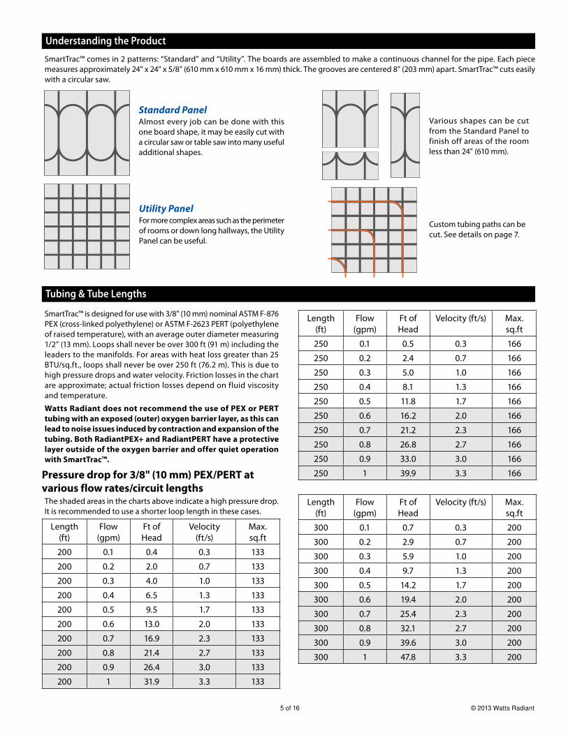
SmartTrac™ comes in 2 patterns: “Standard” and “Utility”. The boards are assembled to make a continuous channel for the pipe. Each piece
measures approximately 24" x 24" x 5/8" (610 mm x 610 mm x 16 mm) thick. The grooves are centered 8" (203 mm) apart. SmartTrac™ cuts easily
with a circular saw.
Utility Panel For more complex areas such as the perimeter
of rooms or down long hallways, the Utility
Panel can be useful.
Various shapes can be cut
from the Standard Panel to
finish off areas of the room
less than 24" (610 mm).
Understanding the Product
Standard PanelAlmost every job can be done with this
one board shape, it may be easily cut with
a circular saw or table saw into many useful
additional shapes.
SmartTrac™ is designed for use with 3/8" (10 mm) nominal ASTM F-876
PEX (cross-linked polyethylene) or ASTM F-2623 PERT (polyethylene
of raised temperature), with an average outer diameter measuring
1/2" (13 mm). Loops shall never be over 300 ft (91 m) including the
leaders to the manifolds. For areas with heat loss greater than 25
BTU/sq.ft., loops shall never be over 250 ft (76.2 m). This is due to
high pressure drops and water velocity. Friction losses in the chart
are approximate; actual friction losses depend on fluid viscosity
and temperature.
Watts Radiant does not recommend the use of PEX or PERT
tubing with an exposed (outer) oxygen barrier layer, as this can
lead to noise issues induced by contraction and expansion of the
tubing. Both RadiantPEX+ and RadiantPERT have a protective
layer outside of the oxygen barrier and offer quiet operation
with SmartTrac™.
Pressure drop for 3/8" (10 mm) PEX/PERT at
various flow rates/circuit lengthsThe shaded areas in the charts above indicate a high pressure drop.
It is recommended to use a shorter loop length in these cases.
Length
(ft)
Flow
(gpm)
Ft of
Head
Velocity
(ft/s)
Max.
sq.ft
200 0.1 0.4 0.3 133
200 0.2 2.0 0.7 133
200 0.3 4.0 1.0 133
200 0.4 6.5 1.3 133
200 0.5 9.5 1.7 133
200 0.6 13.0 2.0 133
200 0.7 16.9 2.3 133
200 0.8 21.4 2.7 133
200 0.9 26.4 3.0 133
200 1 31.9 3.3 133
Tubing & Tube Lengths
Length
(ft)
Flow
(gpm)
Ft of
Head
Velocity (ft/s) Max.
sq.ft
250 0.1 0.5 0.3 166
250 0.2 2.4 0.7 166
250 0.3 5.0 1.0 166
250 0.4 8.1 1.3 166
250 0.5 11.8 1.7 166
250 0.6 16.2 2.0 166
250 0.7 21.2 2.3 166
250 0.8 26.8 2.7 166
250 0.9 33.0 3.0 166
250 1 39.9 3.3 166
Length
(ft)
Flow
(gpm)
Ft of
Head
Velocity (ft/s) Max.
sq.ft
300 0.1 0.7 0.3 200
300 0.2 2.9 0.7 200
300 0.3 5.9 1.0 200
300 0.4 9.7 1.3 200
300 0.5 14.2 1.7 200
300 0.6 19.4 2.0 200
300 0.7 25.4 2.3 200
300 0.8 32.1 2.7 200
300 0.9 39.6 3.0 200
300 1 47.8 3.3 200
Custom tubing paths can be
cut. See details on page 7.
IOM-WR-SmartTrac 1340 6 of 16
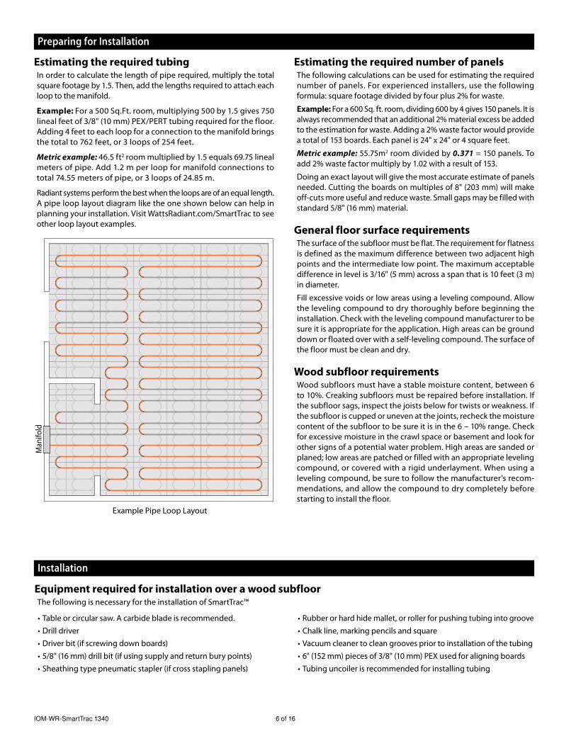
Estimating the required tubingIn order to calculate the length of pipe required, multiply the total
square footage by 1.5. Then, add the lengths required to attach each
loop to the manifold.
Example: For a 500 Sq.Ft. room, multiplying 500 by 1.5 gives 750
lineal feet of 3/8" (10 mm) PEX/PERT tubing required for the floor.
Adding 4 feet to each loop for a connection to the manifold brings
the total to 762 feet, or 3 loops of 254 feet.
Metric example: 46.5 ft2 room multiplied by 1.5 equals 69.75 lineal
meters of pipe. Add 1.2 m per loop for manifold connections to
total 74.55 meters of pipe, or 3 loops of 24.85 m.
Radiant systems perform the best when the loops are of an equal length.
A pipe loop layout diagram like the one shown below can help in
planning your installation. Visit WattsRadiant.com/SmartTrac to see
other loop layout examples.
Estimating the required number of panelsThe following calculations can be used for estimating the required
number of panels. For experienced installers, use the following
formula: square footage divided by four plus 2% for waste.
Example: For a 600 Sq. ft. room, dividing 600 by 4 gives 150 panels. It is
always recommended that an additional 2% material excess be added
to the estimation for waste. Adding a 2% waste factor would provide
a total of 153 boards. Each panel is 24" x 24" or 4 square feet.
Metric example: 55.75m2 room divided by 0.371 = 150 panels. To
add 2% waste factor multiply by 1.02 with a result of 153.
Doing an exact layout will give the most accurate estimate of panels
needed. Cutting the boards on multiples of 8" (203 mm) will make
off-cuts more useful and reduce waste. Small gaps may be filled with
standard 5/8" (16 mm) material.
General floor surface requirementsThe surface of the subfloor must be flat. The requirement for flatness
is defined as the maximum difference between two adjacent high
points and the intermediate low point. The maximum acceptable
difference in level is 3/16" (5 mm) across a span that is 10 feet (3 m)
in diameter.
Fill excessive voids or low areas using a leveling compound. Allow
the leveling compound to dry thoroughly before beginning the
installation. Check with the leveling compound manufacturer to be
sure it is appropriate for the application. High areas can be ground
down or floated over with a self-leveling compound. The surface of
the floor must be clean and dry.
Wood subfloor requirements Wood subfloors must have a stable moisture content, between 6
to 10%. Creaking subfloors must be repaired before installation. If
the subfloor sags, inspect the joists below for twists or weakness. If
the subfloor is cupped or uneven at the joints, recheck the moisture
content of the subfloor to be sure it is in the 6 – 10% range. Check
for excessive moisture in the crawl space or basement and look for
other signs of a potential water problem. High areas are sanded or
planed; low areas are patched or filled with an appropriate leveling
compound, or covered with a rigid underlayment. When using a
leveling compound, be sure to follow the manufacturer’s recom-
mendations, and allow the compound to dry completely before
starting to install the floor.
Preparing for Installation
Installation
Table or circular saw. A carbide blade is recommended.
Drill driver
Driver bit (if screwing down boards)
5/8" (16 mm) drill bit (if using supply and return bury points)
Sheathing type pneumatic stapler (if cross stapling panels)
•
•
•
•
•
Example Pipe Loop Layout
Man
ifo
ld
Rubber or hard hide mallet, or roller for pushing tubing into groove
Chalk line, marking pencils and square
Vacuum cleaner to clean grooves prior to installation of the tubing
6" (152 mm) pieces of 3/8" (10 mm) PEX used for aligning boards
Tubing uncoiler is recommended for installing tubing
•
•
•
•
•
Equipment required for installation over a wood subfloorThe following is necessary for the installation of SmartTrac™
7 of 16 © 2013 Watts Radiant
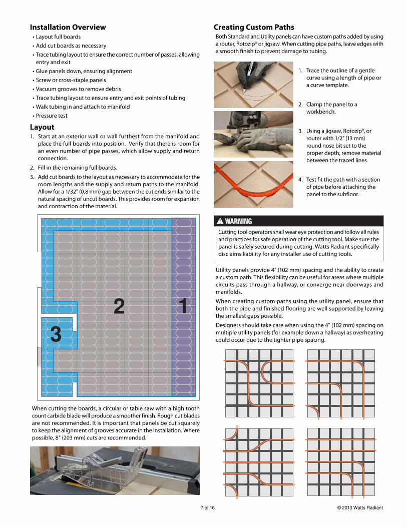
Layout1. Start at an exterior wall or wall furthest from the manifold and
place the full boards into position. Verify that there is room for
an even number of pipe passes, which allow supply and return
connection.
2. Fill in the remaining full boards.
3. Add cut boards to the layout as necessary to accommodate for the
room lengths and the supply and return paths to the manifold.
Allow for a 1/32" (0.8 mm) gap between the cut ends similar to the
natural spacing of uncut boards. This provides room for expansion
and contraction of the material.
When cutting the boards, a circular or table saw with a high tooth
count carbide blade will produce a smoother finish. Rough cut blades
are not recommended. It is important that panels be cut squarely
to keep the alignment of grooves accurate in the installation. Where
possible, 8" (203 mm) cuts are recommended.
Installation OverviewLayout full boards
Add cut boards as necessary
Trace tubing layout to ensure the correct number of passes, allowing
entry and exit
Glue panels down, ensuring alignment
Screw or cross-staple panels
Vacuum grooves to remove debris
Trace tubing layout to ensure entry and exit points of tubing
Walk tubing in and attach to manifold
Pressure test
•
•
•
•
•
•
•
•
•
Creating Custom PathsBoth Standard and Utility panels can have custom paths added by using
a router, Rotozip® or jigsaw. When cutting pipe paths, leave edges with
a smooth finish to prevent damage to tubing.
Cutting tool operators shall wear eye protection and follow all rules
and practices for safe operation of the cutting tool. Make sure the
panel is safely secured during cutting. Watts Radiant specifically
disclaims liability for any installer use of cutting tools.
Utility panels provide 4" (102 mm) spacing and the ability to create
a custom path. This flexibility can be useful for areas where multiple
circuits pass through a hallway, or converge near doorways and
manifolds.
When creating custom paths using the utility panel, ensure that
both the pipe and finished flooring are well supported by leaving
the smallest gaps possible.
Designers should take care when using the 4" (102 mm) spacing on
multiple utility panels (for example down a hallway) as overheating
could occur due to the tighter pipe spacing.
123
1. Trace the outline of a gentle
curve using a length of pipe or
a curve template.
2. Clamp the panel to a
workbench.
3. Using a jigsaw, Rotozip®, or
router with 1/2" (13 mm)
round nose bit set to the
proper depth, remove material
between the traced lines.
4. Test fit the path with a section
of pipe before attaching the
panel to the subfloor.
IOM-WR-SmartTrac 1340 8 of 16
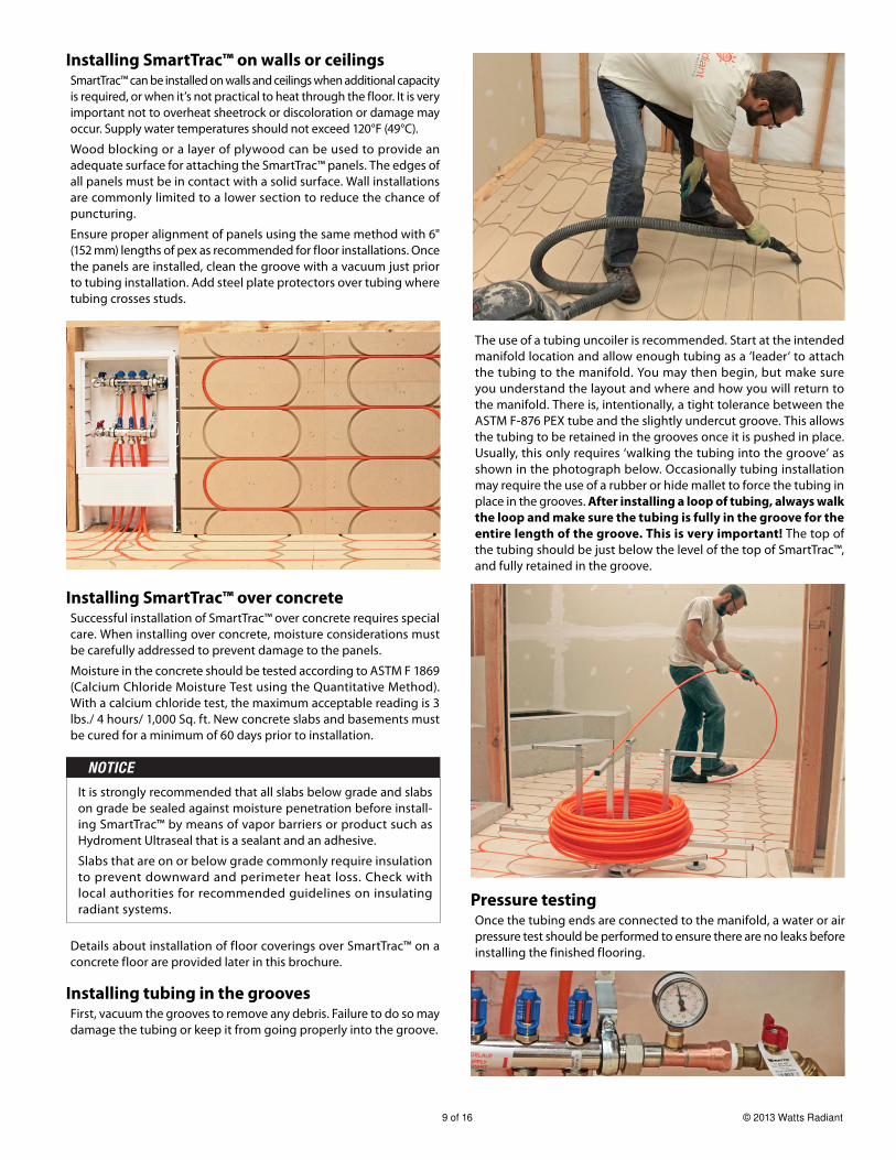
Attaching SmartTrac™ to a subfloorEach SmartTrac™ panel should be glued to a wooden subfloor using
construction adhesive type glue at a minimum 1/8" (3 mm) bead in
the gluing pattern below. Every board should be glued.
The glue may be applied to the underside of the board or to the floor.
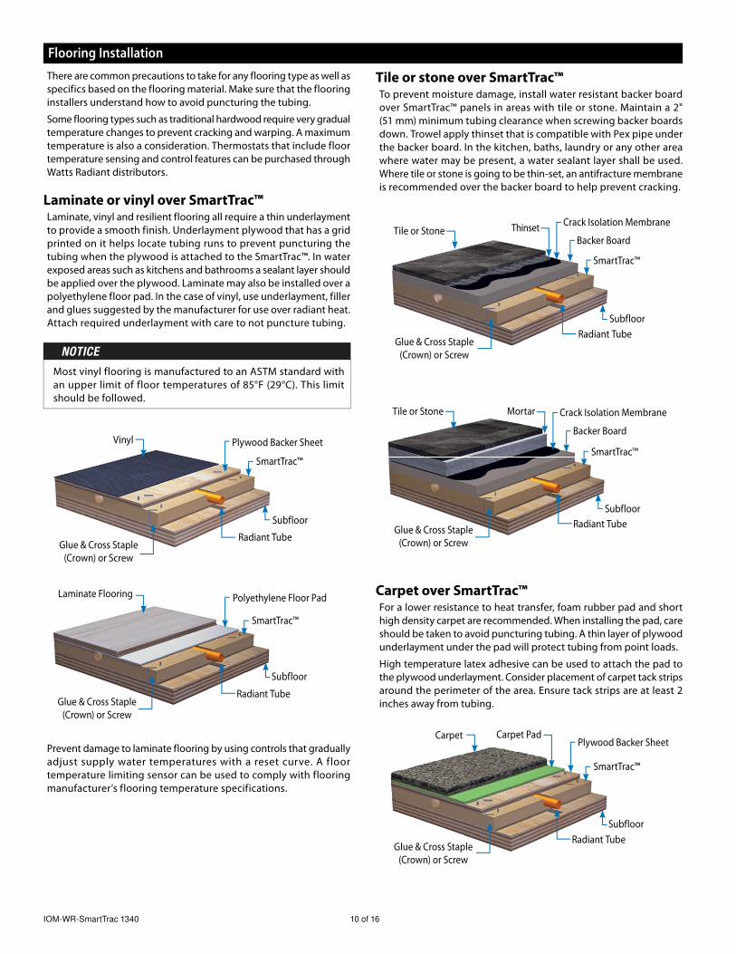
Screw or cross staple boards to the subfloorAfter you have glued SmartTrac™, the boards should be screwed or
cross-stapled to the subfloor (1" (24 mm) long, #8 screws are recom-
mended). On full size pieces (24" x 24" (610 mm x 610 mm)), 10 screws
should be used, 3 on each side and 4 in the middle. This pattern is
shown below (blue arrows indicate attachment points).
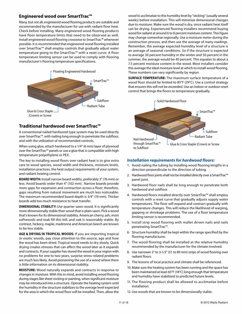
When using staples instead of screws it is very important that
the board is glued and stapled with the same quantity of glue
and staple points as shown in the pattern above. Cross stapling
with a sheathing stapler is the fastest way to install SmartTrac™.
1-1/2" (38 mm) long, 16 gauge staples are recommended. Cross
stapling means 2 staples are put closely together at opposing 45°
angles. (45° angle to the surface)
How to align the grooves correctlyThe easiest way to assure the grooves for the pipe are correctly aligned
between boards is to cut 6" (152 mm) pieces of 3/8" (10 mm) ASTM F-876
PEX/PERT and use them as alignment tools. To do this, get the boards
close to the desired alignment and press a piece of tubing in each
groove, lapping 3" (76 mm) into the groove of each board, as shown
below. After the board is attached, these should be removed.
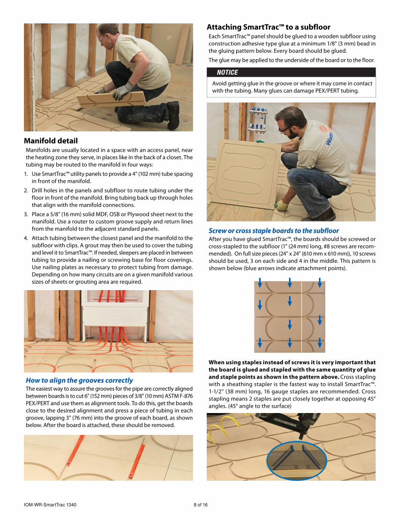
Manifold detailManifolds are usually located in a space with an access panel, near
the heating zone they serve, in places like in the back of a closet. The
tubing may be routed to the manifold in four ways:
1. Use SmartTrac™ utility panels to provide a 4" (102 mm) tube spacing
in front of the manifold.
2. Drill holes in the panels and subfloor to route tubing under the
floor in front of the manifold. Bring tubing back up through holes
that align with the manifold connections.
3. Place a 5/8" (16 mm) solid MDF, OSB or Plywood sheet next to the
manifold. Use a router to custom groove supply and return lines
from the manifold to the adjacent standard panels.
4. Attach tubing between the closest panel and the manifold to the
subfloor with clips. A grout may then be used to cover the tubing
and level it to SmartTrac™. If needed, sleepers are placed in between
tubing to provide a nailing or screwing base for floor coverings.
Use nailing plates as necessary to protect tubing from damage.
Depending on how many circuits are on a given manifold various
sizes of sheets or grouting area are required.
Avoid getting glue in the groove or where it may come in contact
with the tubing. Many glues can damage PEX/PERT tubing.
9 of 16 © 2013 Watts Radiant
Installing tubing in the groovesFirst, vacuum the grooves to remove any debris. Failure to do so may
damage the tubing or keep it from going properly into the groove.
The use of a tubing uncoiler is recommended. Start at the intended
manifold location and allow enough tubing as a ‘leader‘ to attach
the tubing to the manifold. You may then begin, but make sure
you understand the layout and where and how you will return to
the manifold. There is, intentionally, a tight tolerance between the
ASTM F-876 PEX tube and the slightly undercut groove. This allows
the tubing to be retained in the grooves once it is pushed in place.
Usually, this only requires ‘walking the tubing into the groove‘ as
shown in the photograph below. Occasionally tubing installation
may require the use of a rubber or hide mallet to force the tubing in
place in the grooves. After installing a loop of tubing, always walk
the loop and make sure the tubing is fully in the groove for the
entire length of the groove. This is very important! The top of
the tubing should be just below the level of the top of SmartTrac™,
and fully retained in the groove.
Installing SmartTrac™ on walls or ceilingsSmartTrac™ can be installed on walls and ceilings when additional capacity
is required, or when it’s not practical to heat through the floor. It is very
important not to overheat sheetrock or discoloration or damage may
occur. Supply water temperatures should not exceed 120°F (49°C).
Wood blocking or a layer of plywood can be used to provide an
adequate surface for attaching the SmartTrac™ panels. The edges of
all panels must be in contact with a solid surface. Wall installations
are commonly limited to a lower section to reduce the chance of
puncturing.
Ensure proper alignment of panels using the same method with 6"
(152 mm) lengths of pex as recommended for floor installations. Once
the panels are installed, clean the groove with a vacuum just prior
to tubing installation. Add steel plate protectors over tubing where
tubing crosses studs.
Installing SmartTrac™ over concreteSuccessful installation of SmartTrac™ over concrete requires special
care. When installing over concrete, moisture considerations must
be carefully addressed to prevent damage to the panels.
Moisture in the concrete should be tested according to ASTM F 1869
(Calcium Chloride Moisture Test using the Quantitative Method).
With a calcium chloride test, the maximum acceptable reading is 3
lbs./ 4 hours/ 1,000 Sq. ft. New concrete slabs and basements must
be cured for a minimum of 60 days prior to installation.
Pressure testingOnce the tubing ends are connected to the manifold, a water or air
pressure test should be performed to ensure there are no leaks before
installing the finished flooring.Details about installation of floor coverings over SmartTrac™ on a
concrete floor are provided later in this brochure.
It is strongly recommended that all slabs below grade and slabs
on grade be sealed against moisture penetration before install-
ing SmartTrac™ by means of vapor barriers or product such as
Hydroment Ultraseal that is a sealant and an adhesive.
Slabs that are on or below grade commonly require insulation
to prevent downward and perimeter heat loss. Check with
local authorities for recommended guidelines on insulating
radiant systems.
IOM-WR-SmartTrac 1340 10 of 16
Carpet over SmartTrac™For a lower resistance to heat transfer, foam rubber pad and short
high density carpet are recommended. When installing the pad, care
should be taken to avoid puncturing tubing. A thin layer of plywood
underlayment under the pad will protect tubing from point loads.
High temperature latex adhesive can be used to attach the pad to
the plywood underlayment. Consider placement of carpet tack strips
around the perimeter of the area. Ensure tack strips are at least 2
inches away from tubing.
Flooring Installation
There are common precautions to take for any flooring type as well as
specifics based on the flooring material. Make sure that the flooring
installers understand how to avoid puncturing the tubing.
Some flooring types such as traditional hardwood require very gradual
temperature changes to prevent cracking and warping. A maximum
temperature is also a consideration. Thermostats that include floor
temperature sensing and control features can be purchased through
Watts Radiant distributors.
Laminate or vinyl over SmartTrac™Laminate, vinyl and resilient flooring all require a thin underlayment
to provide a smooth finish. Underlayment plywood that has a grid
printed on it helps locate tubing runs to prevent puncturing the
tubing when the plywood is attached to the SmartTrac™. In water
exposed areas such as kitchens and bathrooms a sealant layer should
be applied over the plywood. Laminate may also be installed over a
polyethylene floor pad. In the case of vinyl, use underlayment, filler
and glues suggested by the manufacturer for use over radiant heat.
Attach required underlayment with care to not puncture tubing.
Tile or stone over SmartTrac™To prevent moisture damage, install water resistant backer board
over SmartTrac™ panels in areas with tile or stone. Maintain a 2"
(51 mm) minimum tubing clearance when screwing backer boards
down. Trowel apply thinset that is compatible with Pex pipe under
the backer board. In the kitchen, baths, laundry or any other area
where water may be present, a water sealant layer shall be used.
Where tile or stone is going to be thin-set, an antifracture membrane
is recommended over the backer board to help prevent cracking.
Prevent damage to laminate flooring by using controls that gradually
adjust supply water temperatures with a reset curve. A floor
temperature limiting sensor can be used to comply with flooring
manufacturer’s flooring temperature specifications.
SmartTrac™
Carpet Carpet PadPlywood Backer Sheet
Subfloor
Radiant TubeGlue & Cross Staple
(Crown) or Screw
SmartTrac™
Tile or Stone Mortar
Subfloor
Radiant TubeGlue & Cross Staple
(Crown) or Screw
Crack Isolation Membrane
Backer Board
SmartTrac™
Tile or Stone Thinset
Subfloor
Radiant TubeGlue & Cross Staple
(Crown) or Screw
Crack Isolation Membrane
Backer Board
SmartTrac™
Laminate Flooring Polyethylene Floor Pad
Subfloor
Radiant TubeGlue & Cross Staple
(Crown) or Screw
SmartTrac™
Vinyl Plywood Backer Sheet
Subfloor
Radiant TubeGlue & Cross Staple
(Crown) or Screw
Most vinyl flooring is manufactured to an ASTM standard with
an upper limit of floor temperatures of 85°F (29°C). This limit
should be followed.
11 of 16 © 2013 Watts Radiant
Engineered wood over SmartTrac™Many, but not all, engineered wood flooring products are suitable and
recommended by the manufacturer for use with radiant floor heat.
Check before installing. Many engineered wood flooring products
have floor temperature limits that need to be observed as well.
Install engineered wood flooring crosswise to SmartTrac™ whenever
possible. It is recommended that engineered wood flooring installed
over SmartTrac™ shall employ controls that gradually adjust water
temperature going to the SmartTrac™ with a reset curve. A floor
temperature limiting sensor can be used to comply with flooring
manufacturer’s flooring temperature specifications.
Traditional hardwood over SmartTrac™A conventional nailed hardwood type system may be used directly
over SmartTrac™, with nailing long enough to penetrate the subfloor,
and with the utilization of recommended controls.
When using glue, attach hardwood to a 1/4" (6 mm) layer of plywood
over the SmartTrac™ panels or use a glue that is compatible with high
temperature polyethylene or PEX.
The key to installing wood floors over radiant heat is to give extra
care to wood species, wood width and thickness, moisture levels,
installation practices, the heat output requirements of your system,
and radiant heating control.
BOARD WIDTH: Install narrow board widths, preferably 3" (76 mm) or
less. Avoid boards wider than 4" (102 mm) . Narrow boards provide
more gaps for expansion and contraction across a floor; therefore,
gaps resulting from natural movement are much less noticeable.
The maximum recommended board depth is 3/4" (19 mm). Thicker
boards add too much resistance to heat transfer.
DIMENSIONAL STABILITY: Use quarter sawn wood. It is significantly
more dimensionally stable than wood that is plain sawn. Pick a wood
that’s known for its dimensional stability. American cherry, ash, most
softwoods and teak fill this bill, and oak is reasonably stable. By
contrast, hickory, maple, madronne and American beech are known
to be less stable.
AGE & DRYING IN TROPICAL WOODS: If you are importing tropical
or exotic woods, pay close attention to the source, age and how
the wood has been dried. Tropical wood needs to dry slowly. Quick
drying creates stresses that can affect the wood later as it expands
and contracts. If your supplier has stored the wood in your region with
no problems for one to two years, surprise stress-related problems
are much less likely. Avoid pioneering the use of a wood where there
is little information on its dimensional stability.
MOISTURE: Wood naturally expands and contracts in response to
changes in moisture. With this in mind, avoid installing wood flooring
during stages like sheet rocking or painting, when significant moisture
may be introduced into a structure. Operate the heating system until
the humidity in the structure stabilizes to the average level expected
for the area in which the wood floor will be installed. Then, allow the
Installation requirements for hardwood floors:1. Avoid nailing the tubing by installing wood flooring lengths in a
direction perpendicular to the direction of tubing.
2. Hardwood floor joints shall not be installed directly over a SmartTrac™
panel joint.
3. Hardwood floor nails shall be long enough to penetrate both
hardwood and subfloor.
4. Hardwood floors installed directly over SmartTrac™ shall employ
controls with a reset curve that gradually adjusts supply water
temperatures. The floor will expand and contract gradually with
temperature changes. This will reduce the likelihood of warping,
gapping or shrinkage problems. The use of a floor temperature
limiting sensor is recommended.
5. Install strip wood flooring with mallet driven nails and nails
penetrating SmartTrac™.
6. Structure humidity shall be kept within the range specified by the
flooring manufacturer.
7. The wood flooring shall be installed at the relative humidity
recommended by the manufacturer for the climate involved.
8. Use narrower 2" to 3-1/2" (51 to 89 mm) strips of wood flooring over
radiant floors.
9. The lessons of local practice and climate shall be referenced.
10. Make sure the heating system has been running and the space has
been maintained at least 65°F (18°C) long enough that temperature
and humidity have stabilized to predicted future levels.
11. The flooring product shall be allowed to acclimatize before
installation.
12. Use woods that are known to be dimensionally stable.
wood to acclimatize to this humidity level by “sticking” (usually several
weeks) before installation. This will minimize dimensional changes
due to moisture. Make sure the wood is dry, since radiant heat itself
can be drying. Experienced flooring installers recommend buying
wood for radiant at around 6 to 8 percent moisture content. This figure
may change somewhat regionally. Use a moisture meter during the
construction process, and then use the average of many readings.
Remember, the average expected humidity level of a structure is
an average of seasonal conditions. So if the structure is expected
to average 30 percent humidity in the winter and 50 percent in the
summer, the average would be 40 percent. This equates to about a
7.5 percent moisture content in the wood. Most installers consider
this average the ideal moisture level at which to install wood flooring.
These numbers can vary significantly by region.
SURFACE TEMPERATURE: The maximum surface temperature of a
wood floor should be limited to 85°F (29°C). Use a control strategy
that ensures this will not be exceeded. Use an indoor or outdoor reset
control that brings the floors to temperature gradually.
SmartTrac™
Floating Engineered Hardwood
Subfloor
Radiant Tube
Glue & Cross Staple
(Crown) or ScrewSmartTrac™
Solid Hardwood Floor
Subfloor
Radiant Tube
Glue & Cross Staple (Crown) or Screw
Nail Hardwood
through SmartTrac™
to Subfloor
IOM-WR-SmartTrac 1340 12 of 16
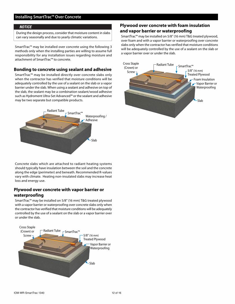
SmartTrac™ may be installed over concrete using the following 3
methods only when the installing parties are willing to assume full
responsibility for any installation issues regarding moisture and
attachment of SmartTrac™ to concrete.
Bonding to concrete using sealant and adhesiveSmartTrac™ may be installed directly over concrete slabs only
when the contractor has verified that moisture conditions will be
adequately controlled by the use of a sealant on the slab or a vapor
barrier under the slab. When using a sealant and adhesive on top of
the slab, the sealant may be a combination sealant/wood adhesive
such as Hydroment Ultra-Set Advanced™ or the sealant and adhesive
may be two separate but compatible products.
Installing SmartTrac™ Over Concrete
Plywood over concrete with vapor barrier or
waterproofingSmartTrac™ may be installed on 5/8" (16 mm) T&G treated plywood
with a vapor barrier or waterproofing over concrete slabs only when
the contractor has verified that moisture conditions will be adequately
controlled by the use of a sealant on the slab or a vapor barrier over
or under the slab.
Plywood over concrete with foam insulation
and vapor barrier or waterproofingSmartTrac™ may be installed on 5/8" (16 mm) T&G treated plywood,
over foam and with a vapor barrier or waterproofing over concrete
slabs only when the contractor has verified that moisture conditions
will be adequately controlled by the use of a sealant on the slab or
a vapor barrier over or under the slab.
SmartTrac™Radiant Tube
Waterproofing / Adhesive
Slab
SmartTrac™
5/8" (16 mm)
Treated Plywood
Radiant Tube
Foam InsulationVapor Barrier or Waterproofing
Slab
Cross Staple
(Crown) or
Screw
SmartTrac™Radiant Tube
Vapor Barrier or Waterproofing
Slab
Cross Staple
(Crown) or
Screw 5/8" (16 mm)
Treated Plywood
During the design process, consider that moisture content in slabs
can vary seasonally and due to yearly climatic variations.
Concrete slabs which are attached to radiant heating systems
should typically have insulation between the soil and the concrete
along the edge (perimeter) and beneath. Recommended R-values
vary with climate. Heating non-insulated slabs may increase heat
loss and energy use.
13 of 16 © 2013 Watts Radiant
Material R-Value Per Inch Typical Thickness Typical R-ValuePlywood 1.1 3/4” (19 mm) 0.825OSB 1.4 3/4” (19 mm) 1.05Softwood 1.1 3/4” (19 mm) 0.825Sheet Vinyl 1.6 1/8” (3 mm) 0.2Vinyl Composition Tile 1.6 1/8” (3 mm) 0.2Linoleum 1.6 1/4” (6 mm) 0.4Linoleum 1.6 1/8” (3 mm) 0.2Dense Rubber Flooring 1.3 21/64” (8 mm) 0.25Recycled Rubber Flooring 2.2 1/2” (13 mm) 1.1Cork 3 1-1/2” (38 mm) 1.125Cork/MDF/Laminate 2.35 1/2” (13 mm) 1.175Brick 2.25 1-1/2” (38 mm) 3.375Marble 0.8 1/2” (13 mm) 0.4Ceramic Tile 1 1/4" (6 mm) 0.25Thinset Mortar 0.4 1/8" (3 mm) 0.05MDF/Plastic Laminate 1 1/2" (13 mm) 0.5Laminate Floor Pad 1.92 5/32" (4 mm) 0.3Engineered Wood 1 1/4" (6 mm) 0.25Engineered Wood 1 3/8" (10 mm) 0.375Engineered Wood 1 5/8" (16 mm) 0.625Engineered Wood 1 3/4" (19 mm) 0.75Engineered Wood Flooring Pad 1.6 1/8" (3 mm) 0.2Engineered Bamboo 0.96 3/4" (19 mm) 0.72Oak 0.85 3/4" (19 mm) 0.638Ash 1 3/4" (19 mm) 0.75Maple 1 3/4" (19 mm) 0.75Pine 1.3 3/4" (19 mm) 0.975Fir 1.2 3/4" (19 mm) 0.9Carpet Pad/Slab Rubber 33lb 1.28 1/4" (6 mm) 0.32Carpet Pad/Slab Rubber 33lb 1.28 3/8" (10 mm) 0.48Carpet Pad/Slab Rubber 33lb 1.28 1/2" (13 mm) 0.64Carpet Pad/Waffle Rubber 25lb 2.48 1/4" (6 mm) 0.62Carpet Pad/Waffle Rubber 25lb 2.48 1/4" (6 mm) 1.24Carpet Pad/Frothed Polyurethane 16lb 3.53 1/8" (3 mm) 0.53Carpet Pad/Frothed Polyurethane 12lb 3.48 1/4" (6 mm) 0.87Carpet Pad/Frothed Polyurethane 10lb 3.22 3/8" (10 mm) 1.2Carpet Pad/Frothed Polyurethane 10lb 3.22 1/2" (13 mm) 1.61Hair Jute 3.88 1/2" (13 mm) 1.94Hair Jute 3.88 21/64" (8 mm) 1.25Synthetic Fiber Pad 20 oz 1.8 15/64" (6 mm) 0.421Synthetic Fiber Pad 27 oz 1.98 18/64" (7 mm) 0.545Synthetic Fiber Pad 32 oz 2.1 19/64" (8 mm) 0.63Synthetic Fiber Pad 40 oz 2.2 11/32" (9 mm) 0.77Prime Urethane 4.3 21/64" (8 mm) 1.4Prime Urethane 4.3 1/2" (13 mm) 2.15Bonded Urethane 4.2 21/64" (8 mm) 1.35Bonded Urethane 4.2 1/2" (13 mm) 2.1Carpet 2.8 1/4" (6 mm) 0.7Carpet 2.8 3/8" (10 mm) 1.05Carpet 2.8 1/2" (13 mm) 1.4Carpet 2.8 5/8" (16 mm) 1.75Carpet 2.8 3/4" (19 mm) 2.1Wool Carpet 4.2 3/8" (10 mm) 1.575Wool Carpet 4.2 1/2" (13 mm) 2.1
Appendix A - R-Value of Typical Flooring Materials
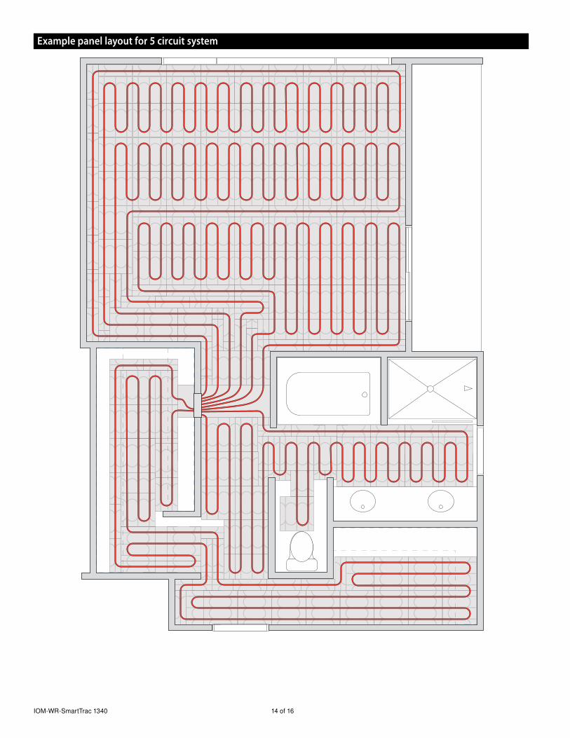
IOM-WR-SmartTrac 1340 14 of 16
Example panel layout for 5 circuit system
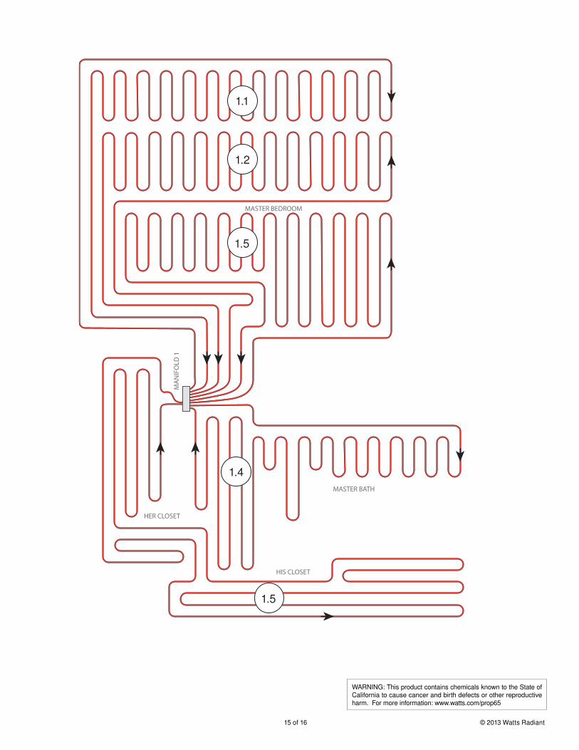
15 of 16 © 2013 Watts Radiant
WARNING: This product contains chemicals known to the State of California to cause cancer and birth defects or other reproductive harm. For more information: www.watts.com/prop65
MA
NIF
OLD
1
HIS CLOSET
MASTER BATH
HER CLOSET
MASTER BEDROOM
1.5
1.4
1.1
1.2
1.5
EDP#2915098
A Watts Water Technologies Company USA: Springfield, MO • Tel. (800) 276-2419 • Fax: (417) 864-8161 • www.wattsradiant.com Canada: Burlington, ONT. • Tel. (888) 208-8927 • Fax: (905) 332-7068 • www.watts.ca
IOM-WR-SmartTrac 1340 © 2013 Watts Radiant
SmartTrac™ Radiant Panel Limited Warranty
Watts Radiant (the Company) warrants its SmartTrac™ Radiant Panel (the Product) to be free from defects in materials and workmanship under normal usage for a period of one year from the documented date of installation of the Product. In the event of defects within the warranty period, the Company will replace the Product without charge. This remedy is the sole and exclusive remedy for breach of warranty. This warranty is transferable to subsequent owners.
Under this Limited Warranty, the Company will provide the following:
In order to make a claim, you must:
(a) Provide the Company with sufficient details relating to the nature of the defect, the installation, the history of operation, and any repairs that may have been made.
(b) At the Company’s discretion and at the owner’s expense, ship the Product to the Company or the Company’s local representative or distributor.
(c) Provide proof that the Product was stored and installed in accordance with the applicable Product Installation Manual and any special written design or installation guidelines by the Company for this project.
(d) Provide a retail sales receipt or proof of purchase.
The following are not covered by this Limited Warranty:
(a) Any incidental or consequential damage, including inconvenience, loss of time or loss of income.(b) Any labor or materials required to repair or replace the Product that are not authorized in writing by the Company.(c) Any labor or materials required to remove, repair or replace materials other than the Products.(d) Any freight or delivery costs related to the Product or any related products.
Watts Radiant assumes no responsibility under this Limited Warranty for any damage to the Product caused by any trades people, visitors on the job site, or damage caused as a result of post-installation work. This Limited Warranty shall be invalidated by any abuse, misuse, misapplication or improper installation of the Products. The staff at the Company is available to answer any questions regarding the proper installation or application of the Product at this toll-free phone number: 800-276-2419 (USA/International) or 888-208-8927 (Canada). If you are ever in doubt about the correct installation procedure to follow, or if the Product appears to be damaged, you must call us before proceeding with the installation or proposed repair.
WATTS RADIANT DISCLAIMS ANY WARRANTY NOT PROVIDED HEREIN, INCLUDING ANY IMPLIED WARRANTY OF MERCHANTABILITY OR IMPLIED WARRANTY OF FITNESS FOR A PARTICULAR PURPOSE. WATTS RADIANT FURTHER DISCLAIMS ANY RESPONSIBILITY FOR SPECIAL, INDIRECT, SECONDARY, INCIDENTAL, OR CONSEQUENTIAL DAMAGES ARISING FROM OWNERSHIP OR USE OF THIS PRODUCT, INCLUDING INCONVENIENCE OR LOSS OF USE. THERE ARE NO WARRANTIES WHICH EXTEND BEYOND THE FACE OF THIS DOCUMENT. NO AGENT OR REPRESENTATIVE OF WATTS RADIANT HAS ANY AUTHORITY TO EXTEND OR MODIFY THIS WARRANTY UNLESS SUCH EXTENSION OR MODIFICATION IS MADE IN WRITING BY A CORPORATE OFFICER.
Some states/provinces do not allow the exclusion or limitation of incidental or consequential damages and some states/provinces do not allow limitations on how long implied warranties may last. Therefore, the above limitations or exclusions may not apply to you. This warranty gives you specific legal rights and you may also have other rights, which vary from state to state or province to province. SO FAR AS IS CONSISTENT WITH APPLICABLE STATE/PROVINCIAL LAW, ANY IMPLIED WARRANTIES THAT MAY NOT BE DISCLAIMED, INCLUDING IMPLIED WARRANTIES OF MERCHANTABILITY OR FITNESS FOR A PARTICULAR PURPOSE ARE LIMITED IN DURATION TO ONE YEAR FROM THE DATE OF MANUFACTURE.
Effective: September 1, 2013. This warranty applies to all Products purchased after this date.