Embed Size (px)
Citation preview

KX-TVA50 Model KX-TVA200
Thank you for purchasing a Panasonic Voice Processing System.Please read this manual carefully before using this product and save this manual for future use.
KX-TVA50/KX-TVA200: Version 1.0
Voice Processing System
Installation Manual
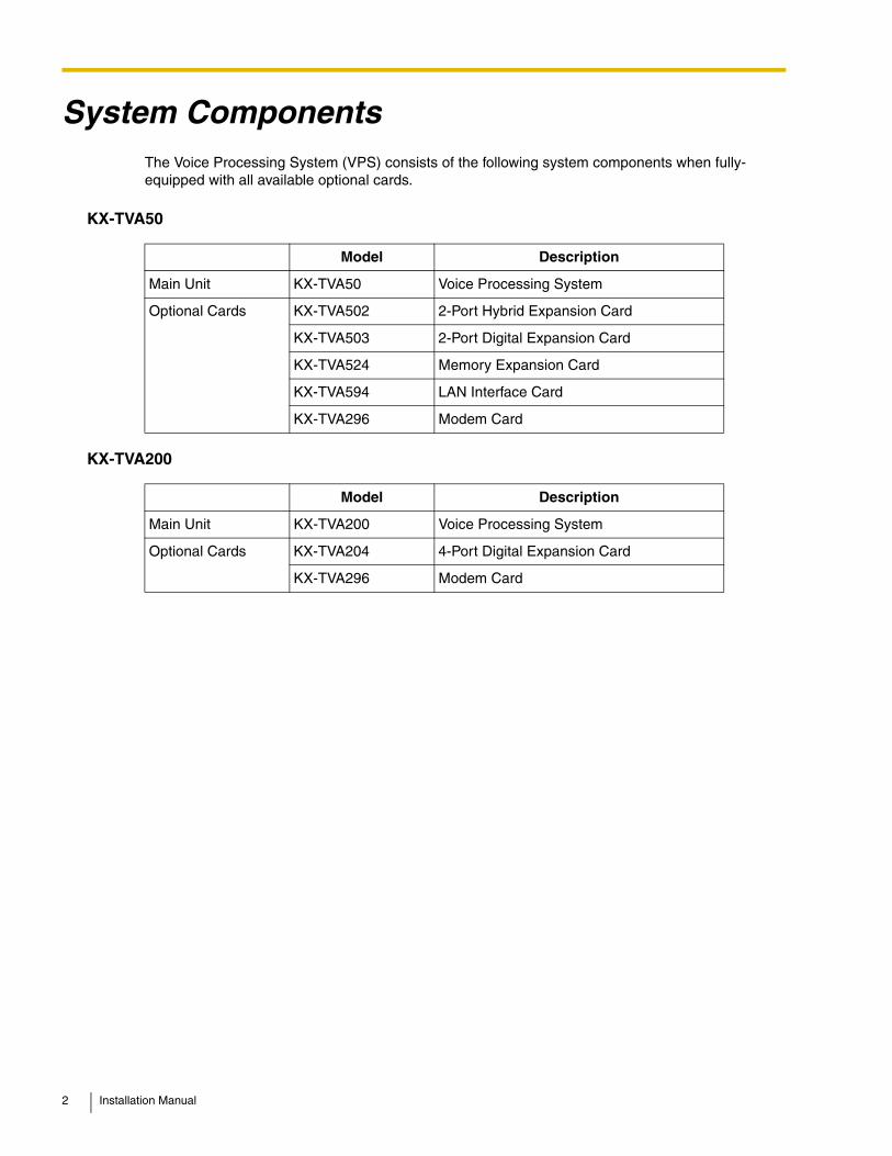
System ComponentsThe Voice Processing System (VPS) consists of the following system components when fully-equipped with all available optional cards.
KX-TVA50
KX-TVA200
Model Description
Main Unit KX-TVA50 Voice Processing System
Optional Cards KX-TVA502 2-Port Hybrid Expansion Card
KX-TVA503 2-Port Digital Expansion Card
KX-TVA524 Memory Expansion Card
KX-TVA594 LAN Interface Card
KX-TVA296 Modem Card
Model Description
Main Unit KX-TVA200 Voice Processing System
Optional Cards KX-TVA204 4-Port Digital Expansion Card
KX-TVA296 Modem Card
2 Installation Manual
Important Safety InstructionsWhen using telephone equipment, basic safety precautions should always be followed to reduce the risk of fire, electric shock and injury to persons, including the following:
• Follow all product warnings, cautions, and instructions.
• Read all the information contained in this manual.
• Close and secure the front cover when the unit is in operation.
• This unit is equipped with a 3–wire grounding plug. The plug will only fit into an grounded power outlet. Do not modify this plug in any way. If it cannot be inserted into the outlet, have the outlet replaced by a licensed electrician.
• This unit is designed to operate at one specific voltage and current setting. The proper voltage and current required for this unit are listed on the product label.
• Do not overload wall outlets. Overloaded outlets could result in fire and/or electrical shock.
• Use only the AC cord included with the unit when connecting the AC adaptor to the power outlet.
• Install the unit so that the AC cord is not obstructed in any way. Do not connect the unit to an extension cord.
• Before touching any internal components, turn off the unit, disconnect the AC adaptor, and wait at least 20 seconds.
• Unplug the AC adaptor before cleaning the unit.
• Do not use solvents, liquid cleaners, water, or abrasive powders to clean the unit. Use only a damp soft cloth for cleaning.
• Do not expose the unit to dust, moisture, condensation, high temperatures (more than 40 [104 ] ), vibration, and direct sunlight.
• Mount the unit on a stable wall surface. Do not mount the unit inside of a separate enclosure unless it is properly ventilated.
• Mount the unit on a surface that is flat and free of obstructions, so that the openings on the back of the unit will not be blocked.
• Do not block the vent slots and openings located on all sides of the unit. Allow at least 20 cm (8 in) of space above and 10 cm (4 in) on the sides of the unit.
• Do not install the unit near water or moisture, heating appliances, or electrical noise generating devices such as televisions, monitors, fluorescent lamps, or electric motors.
• Handle the unit carefully. Do not drop or otherwise expose the unit to physical shock.
• Do not insert wires, pins, or any other material into the unit's vent slots or access points. This could result in electrical shock and serious unit malfunction.
• If the unit malfunctions, disconnect the unit from the telephone line and check the line by reconnecting the telephone. If the telephone operates properly, have the unit repaired by a Panasonic Factory Service Technician.
• Do not disassemble this product. Dangerous electrical shock could result. The unit must only be disassembled and repaired by a Panasonic Factory Service Technician.
• Unplug and transport the unit to a service technician if the AC adaptor or AC cord is frayed or damaged, if the cabinet is cracked or broken, or if the unit has been exposed to moisture, has been dropped, or is not otherwise operating properly.
• Do not use the telephone during a lightning storm or to report a gas leak in the vicinity of the leak.
• The lines connecting the PBX and VPS must never run outside of the building.
• This product is only for connection behind a suitable PBX and should not be connected directly to the network.
˚C
˚F
Installation Manual 3
WARNING
• UNPLUG THIS UNIT FROM POWER OUTLETS IF IT EMITS SMOKE, AN ABNORMAL SMELL OR MAKES UNUSUAL NOISE. THESE CONDITIONS CAN CAUSE FIRE OR ELECTRIC SHOCK. CONFIRM THAT SMOKE HAS STOPPED AND CONTACT AN AUTHORIZED SERVICE CENTER.
• THIS UNIT MAY ONLY BE INSTALLED AND SERVICED BY QUALIFIED SERVICE PERSONNEL.
• WHEN A FAILURE OCCURS WHICH EXPOSES ANY INTERNAL PARTS, DISCONNECT THE POWER SUPPLY CORD IMMEDIATELY AND RETURN THIS UNIT TO YOUR DEALER.
• DISCONNECT THE TELECOM CONNECTION BEFORE DISCONNECTING THE POWER CONNECTION PRIOR TO RELOCATING THE EQUIPMENT, AND RECONNECT THE POWER FIRST.
• TO PREVENT FIRE OR ELECTRICAL SHOCK, DO NOT EXPOSE THIS UNIT TO RAIN OR MOISTURE.
• THIS UNIT IS EQUIPPED WITH AN GROUNDING CONTACT PLUG. FOR SAFETY REASONS, THIS PLUG MUST ONLY BE CONNECTED TO AN GROUNDING CONTACT SOCKET WHICH HAS BEEN INSTALLED ACCORDING TO REGULATIONS.
• THE POWER SUPPLY CORD IS USED AS THE MAIN DISCONNECT DEVICE. ENSURE THAT THE AC OUTLET IS LOCATED NEAR THE EQUIPMENT AND IS EASILY ACCESSIBLE.
CAUTIONDANGER OF EXPLOSION EXISTS IF THE BATTERY IS INCORRECTLY REPLACED. REPLACE THE BATTERY WITH THE SAME OR EQUIVALENT TYPE RECOMMENDED BY THE BATTERY MANUFACTURER. DISPOSE OF USED BATTERIES ACCORDING TO THE MANUFACTURER'S INSTRUCTIONS.
SAVE THESE INSTRUCTIONS
4 Installation Manual
Other InformationWhen you ship the product
Carefully pack and send it prepaid, adequately insured and preferably in the original carton. Attach a postage-paid letter, detailing the symptom, to the outside of the carton. DO NOT send the product to the Executive or Regional Sales offices. They are NOT equipped to make repairs.
Product servicePanasonic Factory Servicenters for this product are listed in the servicenter directory. Consult your certified Panasonic dealer for detailed instructions.
Installation noteThis product is only for connection behind a suitable PBX and should not be connected directly to the network.
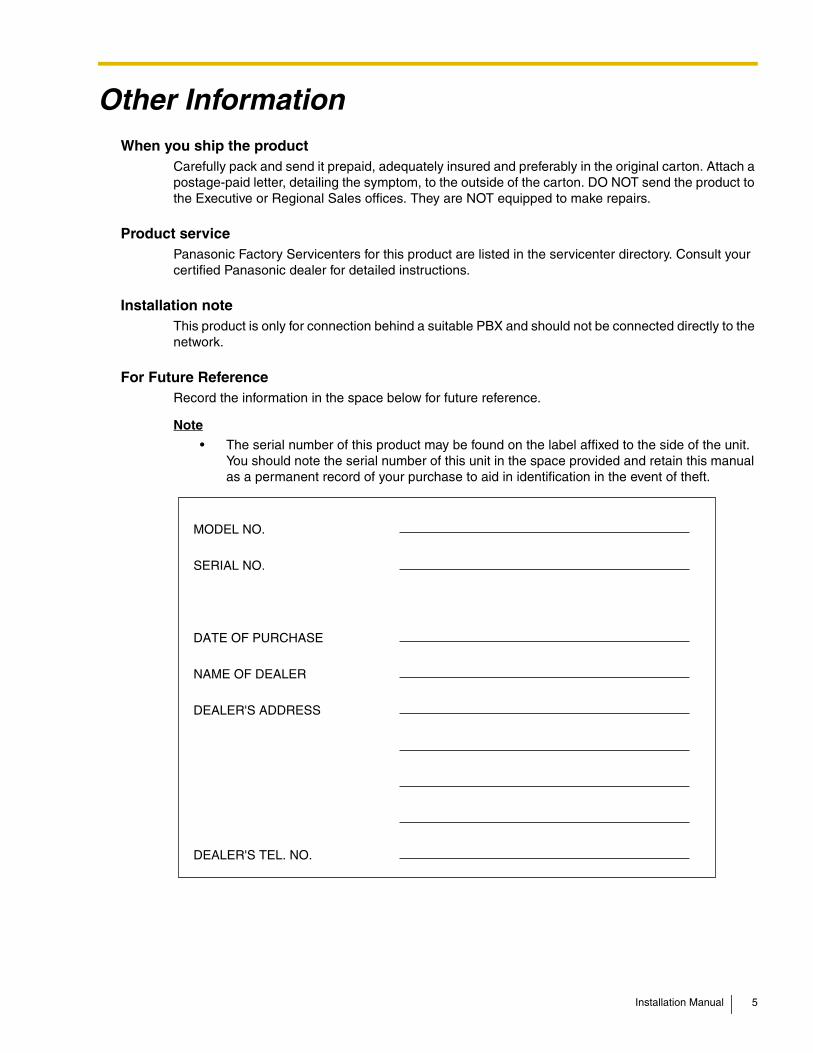
For Future ReferenceRecord the information in the space below for future reference.
Note
• The serial number of this product may be found on the label affixed to the side of the unit. You should note the serial number of this unit in the space provided and retain this manual as a permanent record of your purchase to aid in identification in the event of theft.
MODEL NO.
SERIAL NO.
DATE OF PURCHASE
NAME OF DEALER
DEALER'S ADDRESS
DEALER'S TEL. NO.
Installation Manual 5
F.C.C. REQUIREMENTS AND RELEVANT INFORMATION
This equipment has been tested and found to comply with the limits for a Class B digital device, pursuant to Part 15 of the FCC Rules. These limits are designed to provide reasonable protection against harmful interference in a residential installation. This equipment generates, uses and can radiate radio frequency energy and, if not installed and used in accordance with the instructions, may cause harmful interference to radio communications. However, there is no guarantee that interference will not occur in a particular installation. If this equipment does cause harmful interference to radio or television reception, which can be determined by turning the equipment off and on, the user is encouraged to try to correct the interference by one or more of the following measures.
– Reorient or relocate the receiving antenna.
– Increase the separation between the equipment and receiver.
– Connect the equipment into an outlet on a circuit different from that to which the receiver is connected.
– Consult the dealer or an experienced radio/TV technician for help.
CAUTIONAny changes or modifications not expressly approved by the party responsible for compliance could void the user's authority to operate this device.
The following information applies to when an optional modem card is installed in this product.
Notify The Telephone Company
This equipment complies with Part 68 of the FCC rules and the requirements adopted by the ACTA. On the back of this equipment is a label that contains, among other information, a product identifier in the following format:
• US:AAAEQ##TXXXX
If requested, this number must be provided to the telephone company. Installation must be performed by a qualified professional installer. If required, provide the telephone company with the following technical information:
• The telephone numbers to which the system will be connected
• Make: Panasonic
• Model: KX-TVA50/KX-TVA200
• Ringer Equivalence No. for KX-TVA50: 0.4BRinger Equivalence No. for KX-TVA200: 0.4B
• Facility Interface Code: 02LS2
• Service Order Code: 9.0F
• Required Network Interface Jack: RJ11C
Wiring
A plug and jack used to connect this equipment to the premises wiring and telephone network must comply with the applicable FCC Part 68 rules and requirements adopted by the ACTA. A modular plug is provided with this product. It is designed to be connected to a compatible modular jack that is also compliant. See installation instructions for details.
6 Installation Manual
Ringer Equivalence No. (REN)
The REN is used to determine the number of devices that may be connected to a telephone line. Excessive RENs on a telephone line may result in the devices not ringing in response to an incoming call. In most but not all areas, the sum of RENs should not exceed five (5.0). To be certain of the number of devices that may be connected to a line, as determined by the total RENs, contact the local telephone company. For products approved after July 23, 2001, the REN for this product is part of the product identifier that has the following format:
• US:AAAEQ##TXXXX
The digits represented by ## are the REN without a decimal point (e.g., 03 is a REN of 0.3).
Telephone Service Problems
If this equipment causes harm to the telephone network, the telephone company will notify you in advance that temporary discontinuance of service may be required. But if advance notice isn't practical, the telephone company will notify the customer as soon as possible. Also, you will be advised of your right to file a complaint with the FCC if you believe it is necessary.
Changes in Telephone Company Communications Facilities, Equipment, Operations, and Procedures
The telephone company may make changes in its facilities, equipment, operations or procedures that could affect the operation of the equipment. If this happens the telephone company will provide advance notice in order for you to make necessary modifications to maintain uninterrupted service.
Trouble with this equipment
If trouble is experienced with this equipment, for repair or warranty information, please contact a Factory Servicenter or other Authorized Servicer. If the equipment is causing harm to the telephone network, the telephone company may request that you disconnect the equipment until the problem is resolved. Do not attempt to repair this equipment yourself.
Connection to the Party Line
Connection to party line service is subject to state tariffs. Contact the state public utility commission, public service commission or corporation commission for information.
Combined Use with Alarm Equipment
If your home has specially wired alarm equipment connected to the telephone line, ensure the installation of this equipment does not disable your alarm equipment. If you have questions about what will disable alarm equipment, consult your telephone company or a qualified installer.
Installation Manual 7
IntroductionThank you for purchasing the Panasonic Voice Processing System KX-TVA50/KX-TVA200. We are confident that this product will provide your customer or client with many years of dependable service.
This Installation Manual is designed to serve as an overall technical reference for the KX-TVA50/KX-TVA200.It provides instructions for installing the VPS hardware, configuring the connected PBX for use with the VPS, and getting started with the KX-TVA Maintenance Console software.
The Installation Manual is divided into the following sections:
Section 1 Voice Processing System Overview
This section provides a basic introduction to the VPS and its specifications. It briefly explains what the VPS can do, and how it is connected to and interacts with the PBX.
Section 2 Installation
This section explains how to install the VPS and its optional cards.
Section 3 Installing KX-TVA Maintenance Console
This section explains how to install KX-TVA Maintenance Console on a PC.
Section 4 PBX Programming for APT/DPT Integration
This section explains how to configure compatible Panasonic PBXs to use APT/DPT Integration with the VPS.
Section 5 PBX Programming for Inband Integration (KX-TVA50 only)
This section explains how to configure selected Panasonic PBXs to use Inband Integration with the VPS.
Section 6 Configuring the System
This section explains how to configure the VPS for basic operation.
Section 7 System Maintenance
This section describes how to perform common maintenance procedures.
Glossary
An alphabetical listing of features, terms, and abbreviations, as well as their definitions.
Index
An alphabetical listing of features and terms, as well as the page numbers of related sections.
8 Installation Manual
About the Other ManualsAlong with this Installation Manual, the following manuals are available:
Feature Manual
The Voice Processing System Feature Manual is an overall reference describing VPS features. It explains what the VPS can do, and how to obtain the most of its many features. Sections from the Feature Manual are listed throughout this manual for your reference.
Programming Manual
The Voice Processing System Programming Manual is an overall reference for programming the VPS using KX-TVA Maintenance Console. It explains how to use KX-TVA Maintenance Console and obtain the most out of system administration. Sections from the Programming Manual are listed throughout this manual for your reference.
Subscriber's Manual
The Voice Processing System Subscriber's Manual describes how subscribers can access commonly used VPS features and functions with their extensions and mailboxes. Relevant sections from the Subscriber's Manual are listed throughout this manual for your reference.
Note• For KX-TD500, KX-TDA series, and KX-TAW series PBXs, the term "trunk (CO line)" used in this
manual indicates a trunk (CO line) group.
Trademarks• Microsoft and Windows are either registered trademarks or trademarks of Microsoft Corporation
in the United States and/or other countries.
• Intel and Pentium are trademarks or registered trademarks of Intel Corporation or its subsidiaries in the United States and other countries.
• All other trademarks identified herein are the property of their respective owners.
• Screen shots reprinted with permission from Microsoft Corporation.
Installation Manual 9
Table of Contents
1 Voice Processing System Overview ................................................... 131.1 Basic System Construction ...........................................................................................141.1.1 Main Unit ...........................................................................................................................141.1.2 System Connection Diagram ............................................................................................151.1.3 Options..............................................................................................................................161.1.4 Initial Configuration and Expansion Capabilities ...............................................................161.1.5 Installer Equipment and Software Requirements..............................................................171.1.6 Recommendations for System Configuration....................................................................181.1.7 Compatible PBXs ..............................................................................................................201.2 Voice Mail Integration .....................................................................................................211.2.1 Overview ...........................................................................................................................211.2.2 Connection Examples—KX-TVA50...................................................................................221.2.3 Connection Examples—KX-TVA200.................................................................................251.3 Specifications..................................................................................................................26
2 Installation............................................................................................. 292.1 Before Installation...........................................................................................................302.2 Unpacking........................................................................................................................332.3 Names and Locations.....................................................................................................342.4 Installation Overview ......................................................................................................392.5 Opening/Closing the Covers..........................................................................................402.6 Removing the Dummy Cover Plates..............................................................................442.7 Installing Optional Cards—KX-TVA50...........................................................................452.7.1 2-Port Hybrid Expansion Card (KX-TVA502) ....................................................................462.7.2 2-Port Digital Expansion Card (KX-TVA503).....................................................................482.7.3 Memory Expansion Card (KX-TVA524) ............................................................................502.7.4 LAN Interface Card (KX-TVA594) .....................................................................................512.7.5 Modem Card (KX-TVA296) ...............................................................................................532.8 Installing Optional Cards—KX-TVA200.........................................................................552.8.1 4-Port Digital Expansion Card (KX-TVA204).....................................................................562.8.2 Modem Card (KX-TVA296) ...............................................................................................592.9 PBX Connections............................................................................................................602.9.1 Connecting to the PBX......................................................................................................602.9.2 Modular Plug Connection..................................................................................................612.10 PC Connection ................................................................................................................622.10.1 USB Connection ...............................................................................................................622.10.2 LAN Connection................................................................................................................632.10.3 Modem Connection ...........................................................................................................632.11 Frame Ground Connection.............................................................................................652.12 Connecting the AC Adaptor ...........................................................................................662.13 Securing the Cables........................................................................................................682.14 Initializing the VPS During Installation .........................................................................702.15 Wall Mounting..................................................................................................................712.15.1 Wall Mounting the VPS .....................................................................................................712.15.2 Wall Mounting the AC Adaptor ..........................................................................................75
3 Installing KX-TVA Maintenance Console............................................ 813.1 Overview ..........................................................................................................................82
10 Installation Manual
3.2 KX-TVA Maintenance Console Installation................................................................... 833.3 Starting KX-TVA Maintenance Console ........................................................................ 86
4 PBX Programming for APT/DPT Integration ...................................... 894.1 Guidelines for APT/DPT Integration.............................................................................. 904.1.1 What is APT/DPT Integration?.......................................................................................... 904.1.2 When to Use APT/DPT Integration ................................................................................... 904.1.3 APT/DPT Integration Features.......................................................................................... 904.2 KX-TDA and KX-TAW Series PBX Programming for DPT Integration ........................ 944.3 KX-TA824 PBX Programming for APT Integration ..................................................... 1044.4 KX-TD Series PBX Programming for DPT Integration............................................... 1094.4.1 KX-TD Series PBX Programming via the Manager's Extension ..................................... 1094.4.2 KX-TD1232 Series PBX Programming via the Operating and Maintenance Tool........... 1124.5 KX-TD500 PBX Programming for DPT Integration..................................................... 1144.6 KX-TA Series PBX Programming for APT Integration ............................................... 1214.7 Completing the PBX-VPS Connection ........................................................................ 124
5 PBX Programming for Inband Integration (KX-TVA50 only) ........... 1275.1 Guidelines for Inband Integration ............................................................................... 1285.1.1 What is Inband Integration? ............................................................................................ 1285.1.2 When to Use Inband Integration ..................................................................................... 1285.1.3 PBX Requirements for Inband Integration ...................................................................... 1285.2 PBX Settings for Inband Integration ........................................................................... 1315.2.1 General Guidelines and Definitions ................................................................................ 1315.2.2 Global Parameters .......................................................................................................... 1315.2.3 PBX Interface Parameters .............................................................................................. 1325.3 KX-TDA and KX-TAW Series PBX Programming for Inband Integration.................. 1375.4 KX-TA824 PBX Programming for Inband Integration ................................................ 1465.5 KX-TD Series PBX Programming for Inband Integration .......................................... 1515.5.1 KX-TD Series PBX Programming via the Manager's Extension ..................................... 1515.5.2 KX-TD Series PBX Programming via the Operating and Maintenance Tool................... 1515.6 KX-TD500 PBX Programming for Inband Integration ................................................ 1535.7 KX-TA Series PBX Programming for Inband Integration........................................... 163
6 Configuring the System ..................................................................... 1656.1 Starting Up .................................................................................................................... 1666.1.1 Before Programming....................................................................................................... 1666.1.2 Quick Setup .................................................................................................................... 166
7 System Maintenance .......................................................................... 1817.1 Initializing the VPS........................................................................................................ 1827.2 Backing Up the System................................................................................................ 1857.3 Restarting the VPS ....................................................................................................... 187
Glossary .................................................................................................... 189
Index .......................................................................................................... 203
Installation Manual 11

12 Installation Manual
Section 1
Voice Processing System Overview
This section provides a basic introduction to the VPS and its specifications. It briefly explains what the VPS can do, and how it is connected to and interacts with the PBX.
Installation Manual 13
1.1 Basic System Construction
1.1 Basic System Construction
1.1.1 Main Unit
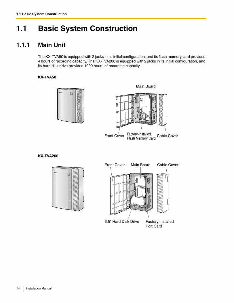
The KX-TVA50 is equipped with 2 jacks in its initial configuration, and its flash memory card provides 4 hours of recording capacity. The KX-TVA200 is equipped with 2 jacks in its initial configuration, and its hard disk drive provides 1000 hours of recording capacity.
KX-TVA50
KX-TVA200
Main Board
Factory-installedFlash Memory Card
Front Cover Cable Cover
Main BoardFront Cover
3.5" Hard Disk Drive
Cable Cover
Factory-installedPort Card
14 Installation Manual
1.1 Basic System Construction
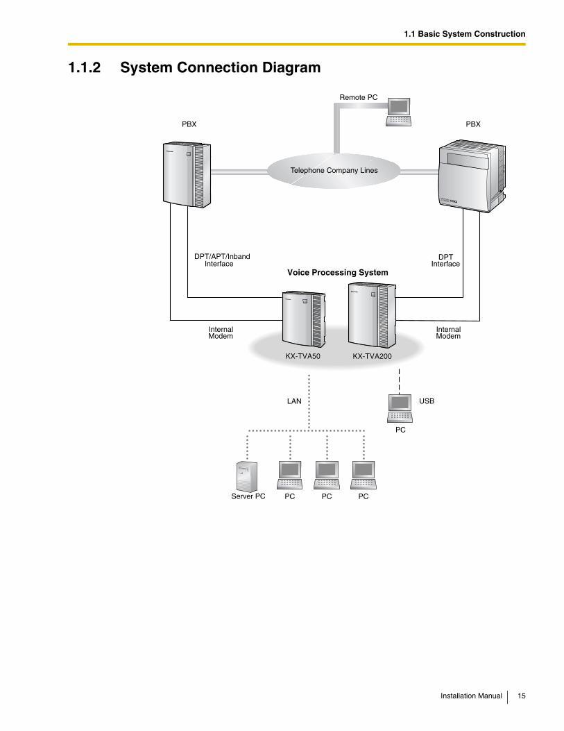
1.1.2 System Connection Diagram
Remote PC
Voice Processing System
PC PC PC
PC
USBLAN
PBXPBX
Server PC
InternalModem
InternalModem
DPT/APT/Inband DPTInterface Interface
KX-TVA50 KX-TVA200KX-TVA50 KX-TVA200
Telephone Company Lines
Installation Manual 15
1.1 Basic System Construction
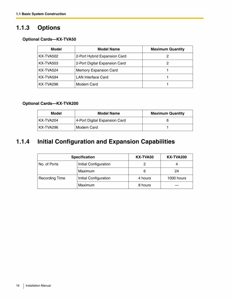
1.1.3 Options
Optional Cards—KX-TVA50
Optional Cards—KX-TVA200
1.1.4 Initial Configuration and Expansion Capabilities
Model Model Name Maximum Quantity
KX-TVA502 2-Port Hybrid Expansion Card 2
KX-TVA503 2-Port Digital Expansion Card 2
KX-TVA524 Memory Expansion Card 1
KX-TVA594 LAN Interface Card 1
KX-TVA296 Modem Card 1
Model Model Name Maximum Quantity
KX-TVA204 4-Port Digital Expansion Card 6
KX-TVA296 Modem Card 1
Specification KX-TVA50 KX-TVA200
No. of Ports Initial Configuration 2 4
Maximum 6 24
Recording Time Initial Configuration 4 hours 1000 hours
Maximum 8 hours —
16 Installation Manual
1.1 Basic System Construction
1.1.5 Installer Equipment and Software Requirements
The installer must use a PC and the KX-TVA Maintenance Console software to configure and customize the VPS. The PC can be connected via the built-in USB port of the VPS, or can access the VPS over a local network via the built-in LAN port (KX-TVA200) or an optional LAN Interface Card (KX-TVA50). Off-site programming is also possible provided an optional Modem Card is installed in the VPS. For more information, see Section 3, Installing KX-TVA Maintenance Console.
Installation Manual 17
1.1 Basic System Construction
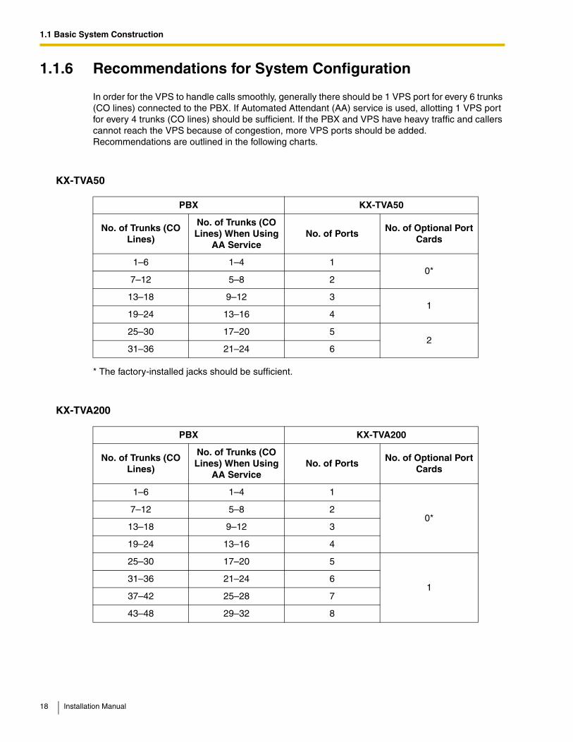
1.1.6 Recommendations for System Configuration
In order for the VPS to handle calls smoothly, generally there should be 1 VPS port for every 6 trunks (CO lines) connected to the PBX. If Automated Attendant (AA) service is used, allotting 1 VPS port for every 4 trunks (CO lines) should be sufficient. If the PBX and VPS have heavy traffic and callers cannot reach the VPS because of congestion, more VPS ports should be added. Recommendations are outlined in the following charts.
KX-TVA50
* The factory-installed jacks should be sufficient.
KX-TVA200
PBX KX-TVA50
No. of Trunks (CO Lines)
No. of Trunks (CO Lines) When Using
AA ServiceNo. of Ports
No. of Optional Port Cards
1–6 1–4 10*
7–12 5–8 2
13–18 9–12 31
19–24 13–16 4
25–30 17–20 52
31–36 21–24 6
PBX KX-TVA200
No. of Trunks (CO Lines)
No. of Trunks (CO Lines) When Using
AA ServiceNo. of Ports
No. of Optional Port Cards
1–6 1–4 1
0*7–12 5–8 2
13–18 9–12 3
19–24 13–16 4
25–30 17–20 5
131–36 21–24 6
37–42 25–28 7
43–48 29–32 8
18 Installation Manual
1.1 Basic System Construction
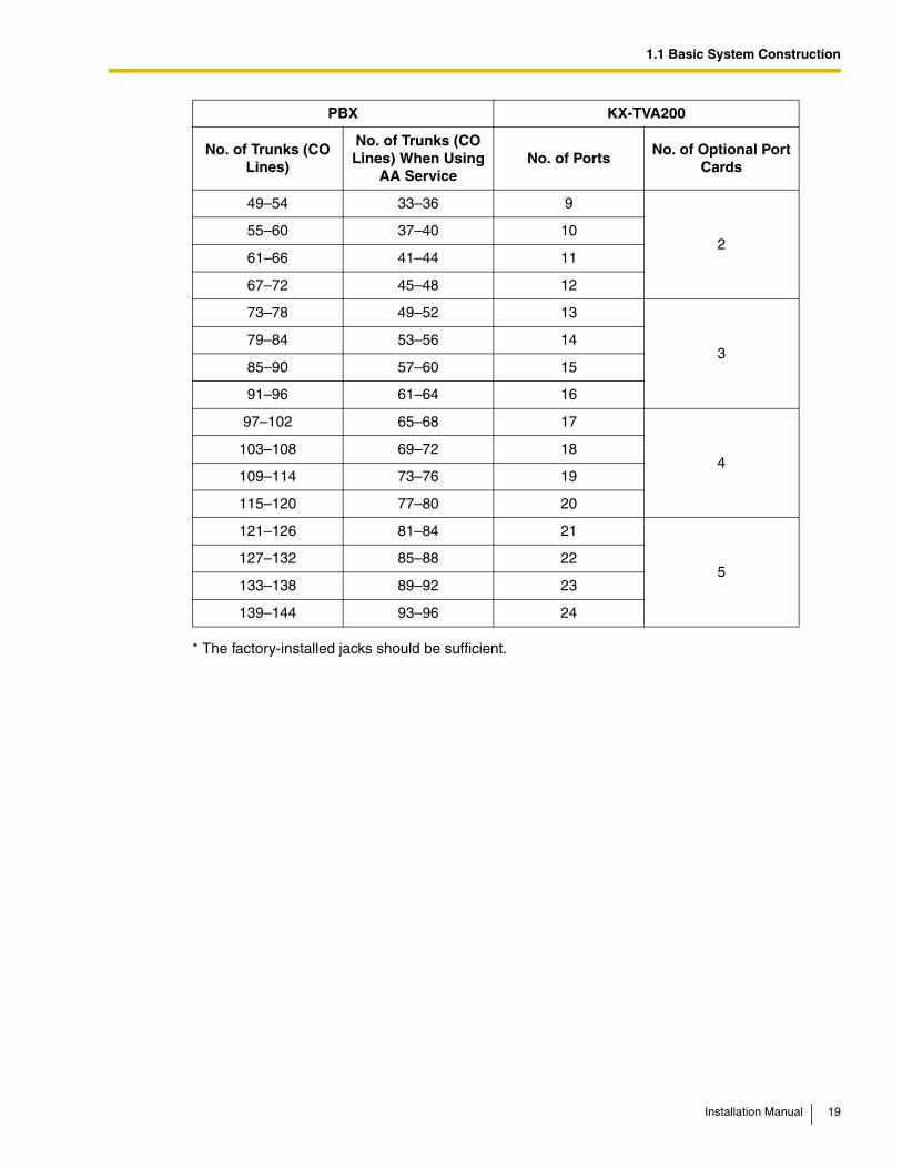
* The factory-installed jacks should be sufficient.
49–54 33–36 9
255–60 37–40 10
61–66 41–44 11
67–72 45–48 12
73–78 49–52 13
379–84 53–56 14
85–90 57–60 15
91–96 61–64 16
97–102 65–68 17
4103–108 69–72 18
109–114 73–76 19
115–120 77–80 20
121–126 81–84 21
5127–132 85–88 22
133–138 89–92 23
139–144 93–96 24
PBX KX-TVA200
No. of Trunks (CO Lines)
No. of Trunks (CO Lines) When Using
AA ServiceNo. of Ports
No. of Optional Port Cards
Installation Manual 19
1.1 Basic System Construction
1.1.7 Compatible PBXs
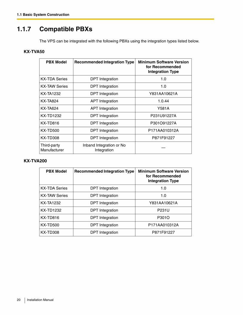
The VPS can be integrated with the following PBXs using the integration types listed below.
KX-TVA50
KX-TVA200
PBX Model Recommended Integration Type Minimum Software Version for Recommended Integration Type
KX-TDA Series DPT Integration 1.0
KX-TAW Series DPT Integration 1.0
KX-TA1232 DPT Integration Y831AA10621A
KX-TA824 APT Integration 1.0.44
KX-TA624 APT Integration Y581A
KX-TD1232 DPT Integration P231U91227A
KX-TD816 DPT Integration P301O91227A
KX-TD500 DPT Integration P171AA010312A
KX-TD308 DPT Integration P871F91227
Third-party Manufacturer
Inband Integration or No Integration
—
PBX Model Recommended Integration Type Minimum Software Version for Recommended Integration Type
KX-TDA Series DPT Integration 1.0
KX-TAW Series DPT Integration 1.0
KX-TA1232 DPT Integration Y831AA10621A
KX-TD1232 DPT Integration P231U
KX-TD816 DPT Integration P301O
KX-TD500 DPT Integration P171AA010312A
KX-TD308 DPT Integration P871F91227
20 Installation Manual
1.2 Voice Mail Integration
1.2 Voice Mail Integration
1.2.1 Overview
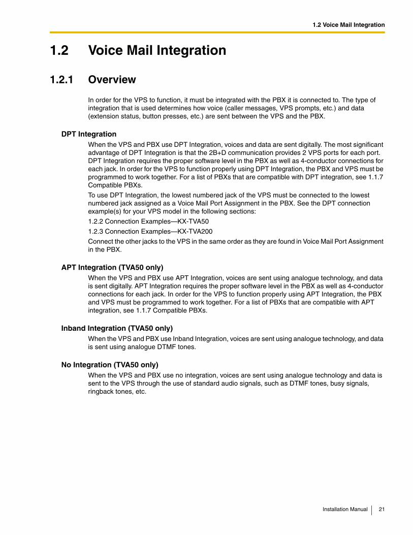
In order for the VPS to function, it must be integrated with the PBX it is connected to. The type of integration that is used determines how voice (caller messages, VPS prompts, etc.) and data (extension status, button presses, etc.) are sent between the VPS and the PBX.
DPT IntegrationWhen the VPS and PBX use DPT Integration, voices and data are sent digitally. The most significant advantage of DPT Integration is that the 2B+D communication provides 2 VPS ports for each port. DPT Integration requires the proper software level in the PBX as well as 4-conductor connections for each jack. In order for the VPS to function properly using DPT Integration, the PBX and VPS must be programmed to work together. For a list of PBXs that are compatible with DPT integration, see 1.1.7 Compatible PBXs.
To use DPT Integration, the lowest numbered jack of the VPS must be connected to the lowest numbered jack assigned as a Voice Mail Port Assignment in the PBX. See the DPT connection example(s) for your VPS model in the following sections:
1.2.2 Connection Examples—KX-TVA50
1.2.3 Connection Examples—KX-TVA200
Connect the other jacks to the VPS in the same order as they are found in Voice Mail Port Assignment in the PBX.
APT Integration (TVA50 only)When the VPS and PBX use APT Integration, voices are sent using analogue technology, and data is sent digitally. APT Integration requires the proper software level in the PBX as well as 4-conductor connections for each jack. In order for the VPS to function properly using APT Integration, the PBX and VPS must be programmed to work together. For a list of PBXs that are compatible with APT integration, see 1.1.7 Compatible PBXs.
Inband Integration (TVA50 only)When the VPS and PBX use Inband Integration, voices are sent using analogue technology, and data is sent using analogue DTMF tones.
No Integration (TVA50 only)When the VPS and PBX use no integration, voices are sent using analogue technology and data is sent to the VPS through the use of standard audio signals, such as DTMF tones, busy signals, ringback tones, etc.
Installation Manual 21
1.2 Voice Mail Integration
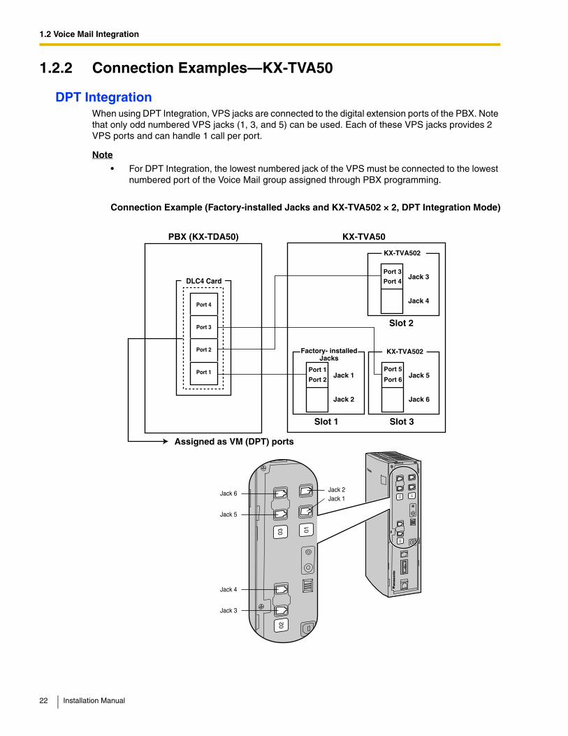
1.2.2 Connection Examples—KX-TVA50
DPT IntegrationWhen using DPT Integration, VPS jacks are connected to the digital extension ports of the PBX. Note that only odd numbered VPS jacks (1, 3, and 5) can be used. Each of these VPS jacks provides 2 VPS ports and can handle 1 call per port.
Note
• For DPT Integration, the lowest numbered jack of the VPS must be connected to the lowest numbered port of the Voice Mail group assigned through PBX programming.
Connection Example (Factory-installed Jacks and KX-TVA502 × 2, DPT Integration Mode)
PBX (KX-TDA50)
Slot 1
Port 2
Port 1
Port 4
Port 3
Port 2
Port 1
KX-TVA50
Assigned as VM (DPT) ports
Jack 1
Jack 2
Factory- installed Jacks
Slot 3
Port 6
Port 5Jack 5
Jack 6
KX-TVA502
Slot 2
Port 4
Port 3Jack 3
Jack 4
KX-TVA502
DLC4 Card
01
0203
01
0203
Jack 6
Jack 5
Jack 2Jack 1
Jack 4
Jack 3
22 Installation Manual
1.2 Voice Mail Integration
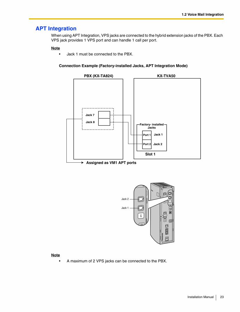
APT IntegrationWhen using APT Integration, VPS jacks are connected to the hybrid extension jacks of the PBX. Each VPS jack provides 1 VPS port and can handle 1 call per port.
Note
• Jack 1 must be connected to the PBX.
Connection Example (Factory-installed Jacks, APT Integration Mode)
Note
• A maximum of 2 VPS jacks can be connected to the PBX.
KX-TVA50PBX (KX-TA824)
Assigned as VM1 APT ports
Jack 7
Jack 8
Port 2
Port 1 Jack 1
Jack 2
Factory- installed Jacks
Slot 1
01
0203
01
Jack 2
Jack 1
Installation Manual 23
1.2 Voice Mail Integration
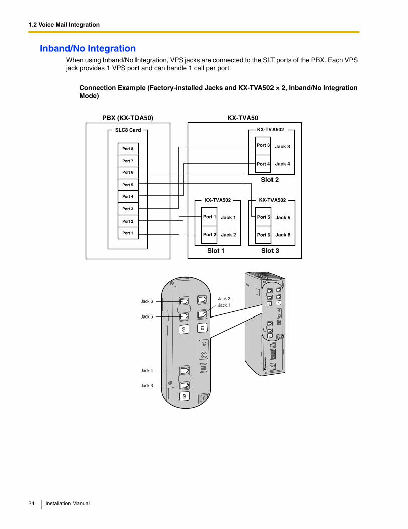
Inband/No IntegrationWhen using Inband/No Integration, VPS jacks are connected to the SLT ports of the PBX. Each VPS jack provides 1 VPS port and can handle 1 call per port.
Connection Example (Factory-installed Jacks and KX-TVA502 × 2, Inband/No Integration Mode)
PBX (KX-TDA50)
Slot 1
Port 2
Port 1
Port 4
Port 5
Port 6
Port 7
Port 8
Port 3
Port 2
Port 1
KX-TVA50
Jack 1
Jack 2
Slot 3
Port 6
Port 5 Jack 5
Jack 6
KX-TVA502 KX-TVA502
Slot 2
Port 4
Port 3 Jack 3
Jack 4
KX-TVA502 SLC8 Card
01
0203
01
0203
Jack 6
Jack 5
Jack 2Jack 1
Jack 4
Jack 3
24 Installation Manual
1.2 Voice Mail Integration
1.2.3 Connection Examples—KX-TVA200
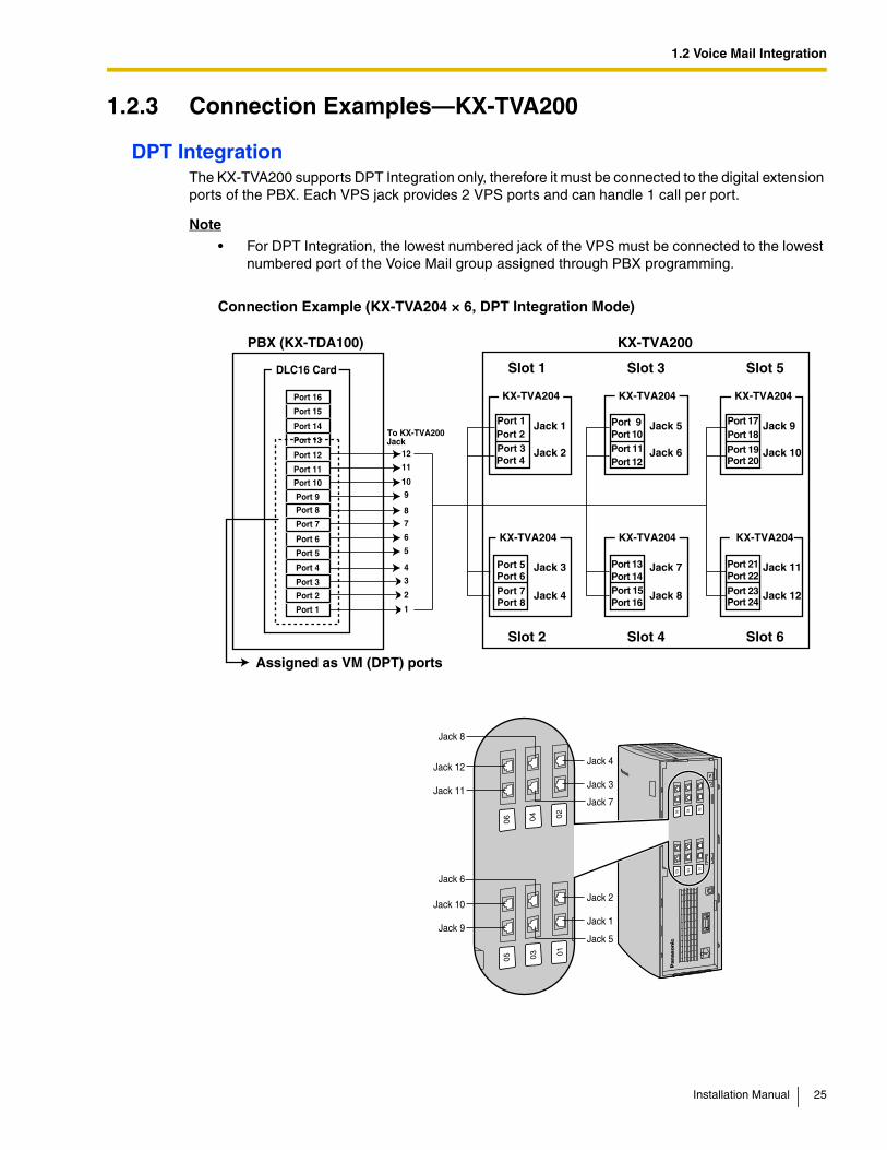
DPT IntegrationThe KX-TVA200 supports DPT Integration only, therefore it must be connected to the digital extension ports of the PBX. Each VPS jack provides 2 VPS ports and can handle 1 call per port.
Note
• For DPT Integration, the lowest numbered jack of the VPS must be connected to the lowest numbered port of the Voice Mail group assigned through PBX programming.
Connection Example (KX-TVA204 × 6, DPT Integration Mode)
PBX (KX-TDA100)
Slot 1
Port 4Port 3Port 2Port 1
Port 4
Port 3
Port 2
Port 1
Port 8
Port 7
Port 6
Port 5
Port 12
Port 11
Port 10
Port 9
Port 16
Port 15
Port 14
Port 13
KX-TVA200
Assigned as VM (DPT) ports
Jack 1
Jack 2
KX-TVA204
Slot 3
Port 10Port 11Port 12
Port 9 Jack 5
Jack 6
KX-TVA204
Slot 5
Port 18Port 17
Port 19Port 20
Port 21Port 22
Port 23Port 24
Jack 10
Jack 9
KX-TVA204
Slot 6
Jack 12
Jack 11
KX-TVA204
Slot 4
Port 14Port 13
Port 15Port 16
Jack 7
Jack 8
KX-TVA204
Slot 2
Port 8Port 7Port 6Port 5 Jack 3
Jack 4
KX-TVA204
DLC16 Card
To KX-TVA200
12
11
109
87
6
5
4
3
2
1
0102
0304
0506
0102
0304
0506
Jack
Jack 12
Jack 8
Jack 4
Jack 3
Jack 7
Jack 2
Jack 1
Jack 11
Jack 10
Jack 9
Jack 6
Jack 5
Installation Manual 25
1.3 Specifications
1.3 Specifications
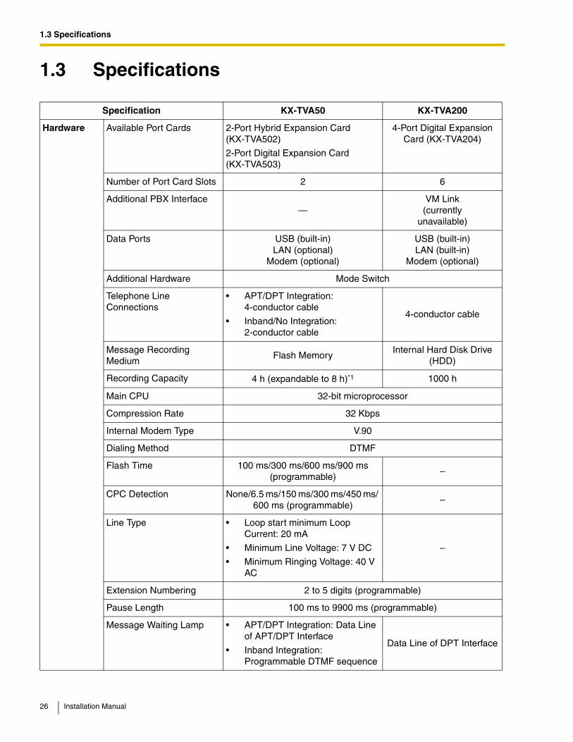
Specification KX-TVA50 KX-TVA200
Hardware Available Port Cards 2-Port Hybrid Expansion Card (KX-TVA502)
2-Port Digital Expansion Card (KX-TVA503)
4-Port Digital Expansion Card (KX-TVA204)
Number of Port Card Slots 2 6
Additional PBX Interface—
VM Link (currently
unavailable)
Data Ports USB (built-in) LAN (optional)
Modem (optional)
USB (built-in) LAN (built-in)
Modem (optional)
Additional Hardware Mode Switch
Telephone Line Connections
• APT/DPT Integration: 4-conductor cable
• Inband/No Integration: 2-conductor cable
4-conductor cable
Message Recording Medium
Flash MemoryInternal Hard Disk Drive
(HDD)
Recording Capacity 4 h (expandable to 8 h)*1 1000 h
Main CPU 32-bit microprocessor
Compression Rate 32 Kbps
Internal Modem Type V.90
Dialing Method DTMF
Flash Time 100 ms/300 ms/600 ms/900 ms (programmable)
–
CPC Detection None/6.5 ms/150 ms/300 ms/450 ms/ 600 ms (programmable)
–
Line Type • Loop start minimum Loop Current: 20 mA
• Minimum Line Voltage: 7 V DC
• Minimum Ringing Voltage: 40 V AC
–
Extension Numbering 2 to 5 digits (programmable)
Pause Length 100 ms to 9900 ms (programmable)
Message Waiting Lamp • APT/DPT Integration: Data Line of APT/DPT Interface
• Inband Integration: Programmable DTMF sequence
Data Line of DPT Interface
26 Installation Manual
1.3 Specifications
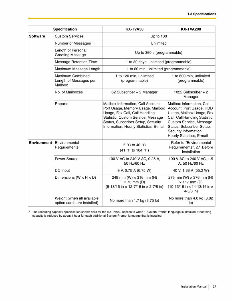
Software Custom Services Up to 100
Number of Messages Unlimited
Length of Personal Greeting Message
Up to 360 s (programmable)
Message Retention Time 1 to 30 days, unlimited (programmable)
Maximum Message Length 1 to 60 min, unlimited (programmable)
Maximum Combined Length of Messages per Mailbox
1 to 120 min, unlimited (programmable)
1 to 600 min, unlimited (programmable)
No. of Mailboxes 62 Subscriber + 2 Manager 1022 Subscriber + 2 Manager
Reports Mailbox Information, Call Account, Port Usage, Memory Usage, Mailbox Usage, Fax Call, Call Handling Statistic, Custom Service, Message Status, Subscriber Setup, Security Information, Hourly Statistics, E-mail
Mailbox Information, Call Account, Port Usage, HDD Usage, Mailbox Usage, Fax Call, Call Handling Statistic, Custom Service, Message Status, Subscriber Setup, Security Information, Hourly Statistics, E-mail
Environment Environmental Requirements
5 to 40 (41 to 104 )
Refer to "Environmental Requirements", 2.1 Before
Installation
Power Source 100 V AC to 240 V AC, 0.25 A, 50 Hz/60 Hz
100 V AC to 240 V AC, 1.5 A, 50 Hz/60 Hz
DC Input 9 V, 0.75 A (6.75 W) 40 V, 1.38 A (55.2 W)
Dimensions (W × H × D) 249 mm (W) × 316 mm (H) × 73 mm (D)
(9-13/16 in × 12-7/16 in × 2-7/8 in)
275 mm (W) × 376 mm (H) × 117 mm (D)
(10-13/16 in × 14-13/16 in × 4-5/8 in)
Weight (when all available option cards are installed)
No more than 1.7 kg (3.75 lb) No more than 4.0 kg (8.82
lb)
*1 The recording capacity specification shown here for the KX-TVA50 applies to when 1 System Prompt language is installed. Recording capacity is reduced by about 1 hour for each additional System Prompt language that is installed.
Specification KX-TVA50 KX-TVA200
˚C ˚C
˚F ˚F
Installation Manual 27

1.3 Specifications
28 Installation Manual
Section 2
Installation
This section explains how to install the VPS and its optional cards.
Installation Manual 29
2.1 Before Installation
2.1 Before InstallationPlease read the following precautions before installing the VPS.
Installation PrecautionsThe VPS should be wall-mounted. Improper placement of the system may result in malfunction, noise, or discoloration. Avoid installing the VPS in the following places:
• in direct sunlight; in hot, cold, or humid places
• in areas where sulfuric gas can damage the equipment (e.g., areas near thermal springs, etc.)
• where shocks or vibrations are frequent or strong
• in dusty places or places where water or oil may come in contact with the unit
• near high frequency generating devices such as sewing machines, elevators or electric welders
• on or near computers or other office equipment, microwave ovens, or air conditioners (Ideally, the VPS should not be installed in the same room with any of these items, and should be at least 2 m (6 ft 7 in) away from televisions.)
Do not obstruct the areas around the PBX and the VPS. Both require open space above the unit for cooling and space on the sides for maintenance and inspection.
Wiring PrecautionsBe sure to follow these instructions when wiring.
• Do not wire the telephone cable parallel to an AC power source, computer, etc. If cables are run near those wires, shield them with metal tubing or use shielded cables and ground the shields.
• Use protectors if running cables on the floor. Avoid running cables under carpets.
• Avoid sharing the power supply to the VPS with computers or other office equipment. Induction noise from such equipment may interrupt the VPS operation.
When making any connections or removing the cover, be sure the power switch is turned off.
When installing telephone wiring, basic safety precautions should always be followed to reduce the risk of fire, electric shock and injury to persons, including the following:
• Never install telephone wiring during a lightning storm.
• Never install telephone jacks in wet locations unless the jack is specifically designed for wet locations.
• Never touch uninsulated telephone wires or terminals unless the telephone line has been disconnected at the network interface.
• Use caution when installing or modifying telephone lines.
Note
• If you live in an area that has frequent power failures, we strongly recommend connecting the VPS and PBX to an uninterruptible power supply (UPS). Use only a UPS which can provide adequate power supply to all connected devices. Refer to the specifications for the power rating of your VPS and PBX.
30 Installation Manual
2.1 Before Installation
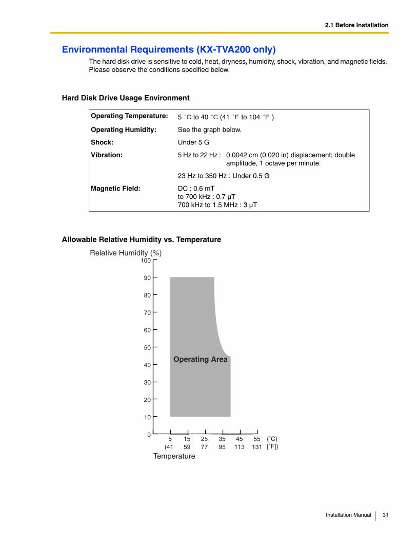
Environmental Requirements (KX-TVA200 only)The hard disk drive is sensitive to cold, heat, dryness, humidity, shock, vibration, and magnetic fields. Please observe the conditions specified below.
Hard Disk Drive Usage Environment
Allowable Relative Humidity vs. Temperature
Operating Temperature: 5 to 40 (41 to 104 )
Operating Humidity: See the graph below.
Shock: Under 5 G
Vibration: 5 Hz to 22 Hz : 0.0042 cm (0.020 in) displacement; double amplitude, 1 octave per minute.
23 Hz to 350 Hz : Under 0.5 G
Magnetic Field: DC : 0.6 mTto 700 kHz : 0.7 µT700 kHz to 1.5 MHz : 3 µT
˚C ˚C ˚F ˚F
0
10
20
30
40
50
60
70
80
90
100
5515 35 45255 (˚C)
Relative Humidity (%)
Temperature
Operating Area
(41 59 77 95 113 131 [˚F])
Installation Manual 31
2.1 Before Installation
Necessary Tools (not supplied)Twisted pair 4-conductor cables are needed for connecting the VPS to the PBX. For the KX-TVA50, twisted pair 2-conductor cables are needed if using Inband or None Integration.
A USB cable is needed when connecting the VPS to the PC that will used for programming via the KX-TVA Maintenance Console.
32 Installation Manual
2.2 Unpacking
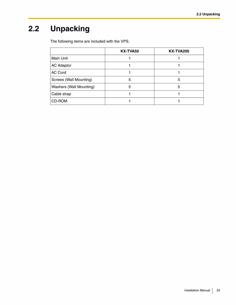
2.2 UnpackingThe following items are included with the VPS.
KX-TVA50 KX-TVA200
Main Unit 1 1
AC Adaptor 1 1
AC Cord 1 1
Screws (Wall Mounting) 5 5
Washers (Wall Mounting) 5 5
Cable strap 1 1
CD-ROM 1 1
Installation Manual 33
2.3 Names and Locations
2.3 Names and Locations
Outside/Inside View
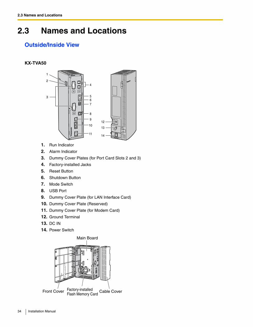
KX-TVA50
1. Run Indicator
2. Alarm Indicator
3. Dummy Cover Plates (for Port Card Slots 2 and 3)
4. Factory-installed Jacks
5. Reset Button
6. Shutdown Button
7. Mode Switch
8. USB Port
9. Dummy Cover Plate (for LAN Interface Card)
10. Dummy Cover Plate (Reserved)
11. Dummy Cover Plate (for Modem Card)
12. Ground Terminal
13. DC IN
14. Power Switch
56
4
8
9
10
11
7
13
12
14
3
2
1
Main Board
Factory-installedFlash Memory Card
Front Cover Cable Cover
34 Installation Manual
2.3 Names and Locations
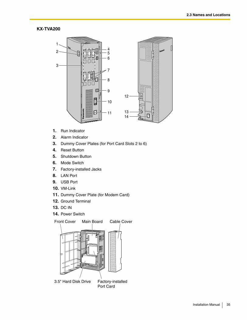
KX-TVA200
1. Run Indicator
2. Alarm Indicator
3. Dummy Cover Plates (for Port Card Slots 2 to 6)
4. Reset Button
5. Shutdown Button
6. Mode Switch
7. Factory-installed Jacks
8. LAN Port
9. USB Port
10. VM-Link
11. Dummy Cover Plate (for Modem Card)
12. Ground Terminal
13. DC IN
14. Power Switch
8
7
654
9
10
11 13
12
14
3
2
1
Main BoardFront Cover
3.5" Hard Disk Drive
Cable Cover
Factory-installedPort Card
Installation Manual 35
2.3 Names and Locations
System Components
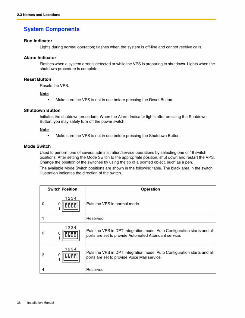
Run IndicatorLights during normal operation; flashes when the system is off-line and cannot receive calls.
Alarm IndicatorFlashes when a system error is detected or while the VPS is preparing to shutdown. Lights when the shutdown procedure is complete.
Reset ButtonResets the VPS.
Note
• Make sure the VPS is not in use before pressing the Reset Button.
Shutdown ButtonInitiates the shutdown procedure. When the Alarm Indicator lights after pressing the Shutdown Button, you may safely turn off the power switch.
Note
• Make sure the VPS is not in use before pressing the Shutdown Button.
Mode SwitchUsed to perform one of several administration/service operations by selecting one of 16 switch positions. After setting the Mode Switch to the appropriate position, shut down and restart the VPS. Change the position of the switches by using the tip of a pointed object, such as a pen.
The available Mode Switch positions are shown in the following table. The black area in the switch illustration indicates the direction of the switch.
Switch Position Operation
0 Puts the VPS in normal mode.
1 Reserved
2Puts the VPS in DPT Integration mode. Auto Configuration starts and all ports are set to provide Automated Attendant service.
3Puts the VPS in DPT Integration mode. Auto Configuration starts and all ports are set to provide Voice Mail service.
4 Reserved
01
1 2 3 4
01
1 2 3 4
01
1 2 3 4
36 Installation Manual
2.3 Names and Locations
When setting the Mode Switch to any position (except 0):
1. Disconnect the port cables from the VPS.
2. Turn the power switch off.
3. Set the Mode Switch.
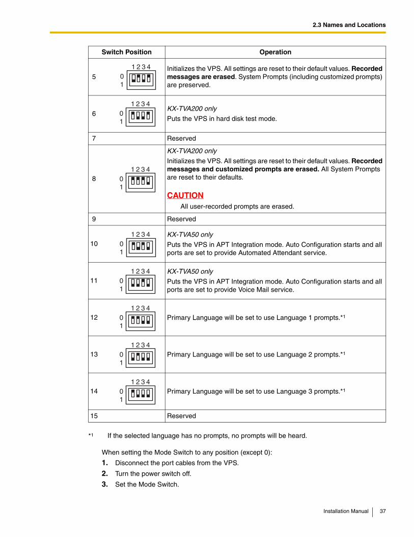
5Initializes the VPS. All settings are reset to their default values. Recorded messages are erased. System Prompts (including customized prompts) are preserved.
6KX-TVA200 only
Puts the VPS in hard disk test mode.
7 Reserved
8
KX-TVA200 only
Initializes the VPS. All settings are reset to their default values. Recorded messages and customized prompts are erased. All System Prompts are reset to their defaults.
CAUTIONAll user-recorded prompts are erased.
9 Reserved
10KX-TVA50 only
Puts the VPS in APT Integration mode. Auto Configuration starts and all ports are set to provide Automated Attendant service.
11 KX-TVA50 only
Puts the VPS in APT Integration mode. Auto Configuration starts and all ports are set to provide Voice Mail service.
12 Primary Language will be set to use Language 1 prompts.*1
13 Primary Language will be set to use Language 2 prompts.*1
14 Primary Language will be set to use Language 3 prompts.*1
15 Reserved
*1 If the selected language has no prompts, no prompts will be heard.
Switch Position Operation
01
1 2 3 4
01
1 2 3 4
01
1 2 3 4
01
1 2 3 4
01
1 2 3 4
01
1 2 3 4
01
1 2 3 4
01
1 2 3 4
Installation Manual 37
2.3 Names and Locations
4. Turn the power switch back on.
5. Connect the port cables.
6. Confirm that the Run Indicator blinks the same number of times as the Mode Switch position (e.g., 5 blinks for switch position 5, etc.).
• This may take several minutes. The Alarm Indicator and Run Indicator will first blink intermittently before the Run Indicator blinks to indicate the Mode Switch position.
7. Turn the power switch off at the VPS.
8. Set the Mode Switch to position 0.
9. Turn the power switch back on at the VPS.
LAN Port (Optional for KX-TVA50)Used to access the VPS over an Ethernet network.
USB PortUsed to access the VPS via USB.
VM Link (Currently unavailable)A VPS-PBX connection interface to be implemented in the future via software upgrade.
Ground Terminal
Must be connected to an ground source with less than 1 resistance.
DC INUsed to supply power to the VPS from the AC Adaptor.
Power SwitchStarts the system and begins the self-test.
SAFETY PRECAUTION: When making any connections or removing the cover, be sure the power switch is turned off.
Factory Installed Flash Memory Card (KX-TVA50 only)Stores all system programming and system prompts, and allows up to 4 hours of message recording time.
Hard Disk Drive (KX-TVA200 only)Stores all system programming and system prompts, and allows up to 1000 hours of message recording time.
Note
• The actual hard disk drive mounted on your VPS may look different from the ones illustrated in this manual.
38 Installation Manual
2.4 Installation Overview
2.4 Installation OverviewThe following is an overview of the steps needed to install optional cards and prepare the VPS hardware for use. Once hardware installation is complete, see Configuring the System for instructions on software setup and VPS customization.
CAUTIONThe information below is only intended as an overview of the installation process. When installing the VPS, refer to the sections listed below for detailed instructions.
1. Open the covers (see 2.5 Opening/Closing the Covers).
2. Remove the Dummy Cover Plates (see 2.6 Removing the Dummy Cover Plates).
3. Install the optional cards (see 2.7 Installing Optional Cards—KX-TVA50 or 2.8 Installing Optional Cards—KX-TVA200).
4. Connect the VPS to the appropriate extension ports of the PBX (see 1.2.2 Connection Examples—KX-TVA50 or 1.2.3 Connection Examples—KX-TVA200). Use 4-conductor or 2-conductor cable as necessary (see 2.9 PBX Connections).
5. Connect the VPS to the PC to be used for programming (see 2.10 PC Connection).
6. Connect the VPS to ground (see 2.11 Frame Ground Connection).
7. Connect the AC adaptor to the VPS and to the power outlet (see 2.12 Connecting the AC Adaptor).
CAUTIONThe power cord is the main disconnect device. Make sure that the power outlet is located near the VPS and is easily accessible.
8. Secure the cables (see 2.13 Securing the Cables).
9. Initialize the VPS (see 2.14 Initializing the VPS During Installation).
10. Close the covers (see 2.5 Opening/Closing the Covers).
11. Wall mount the VPS and AC adaptor (see 2.15 Wall Mounting).
CAUTIONTo turn off the power on the VPS, first press the Shutdown button, wait for the Alarm Indicator to light, then turn off the power switch. Turning off the power switch before the Alarm Indicator lights may cause the VPS to take an exceptionally long time (up to 10 minutes) to start up the next time the power is turned on.
Installation Manual 39
2.5 Opening/Closing the Covers
2.5 Opening/Closing the CoversThe model shown here is the KX-TVA200, however this procedure is the same for the KX-TVA50.
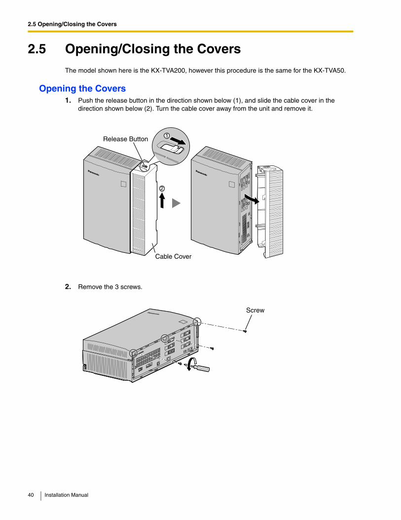
Opening the Covers1. Push the release button in the direction shown below (1), and slide the cable cover in the
direction shown below (2). Turn the cable cover away from the unit and remove it.
2. Remove the 3 screws.
1Release Button
Cable Cover
Screw
40 Installation Manual
2.5 Opening/Closing the Covers
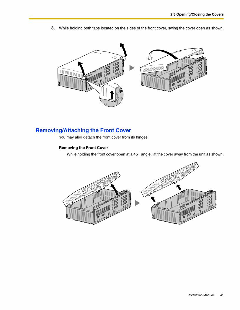
3. While holding both tabs located on the sides of the front cover, swing the cover open as shown.
Removing/Attaching the Front CoverYou may also detach the front cover from its hinges.
Removing the Front Cover
While holding the front cover open at a 45 angle, lift the cover away from the unit as shown.˚
Installation Manual 41
2.5 Opening/Closing the Covers
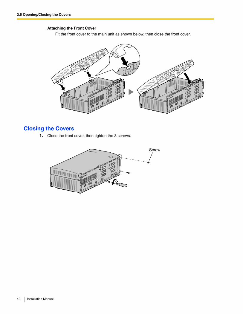
Attaching the Front Cover
Fit the front cover to the main unit as shown below, then close the front cover.
Closing the Covers1. Close the front cover, then tighten the 3 screws.
Screw
42 Installation Manual
2.5 Opening/Closing the Covers
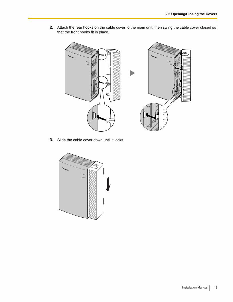
2. Attach the rear hooks on the cable cover to the main unit, then swing the cable cover closed so that the front hooks fit in place.
3. Slide the cable cover down until it locks.
Installation Manual 43
2.6 Removing the Dummy Cover Plates
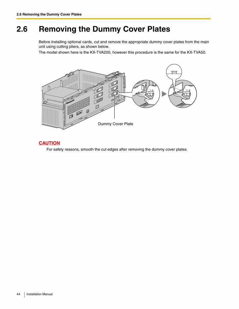
2.6 Removing the Dummy Cover PlatesBefore installing optional cards, cut and remove the appropriate dummy cover plates from the main unit using cutting pliers, as shown below.
The model shown here is the KX-TVA200, however this procedure is the same for the KX-TVA50.
CAUTIONFor safety reasons, smooth the cut edges after removing the dummy cover plates.
Dummy Cover Plate
44 Installation Manual
2.7 Installing Optional Cards—KX-TVA50
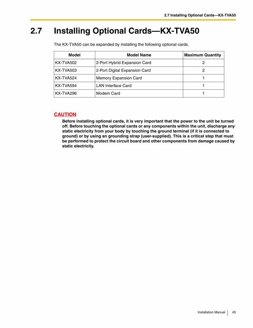
2.7 Installing Optional Cards—KX-TVA50The KX-TVA50 can be expanded by installing the following optional cards.
CAUTIONBefore installing optional cards, it is very important that the power to the unit be turned off. Before touching the optional cards or any components within the unit, discharge any static electricity from your body by touching the ground terminal (if it is connected to ground) or by using an grounding strap (user-supplied). This is a critical step that must be performed to protect the circuit board and other components from damage caused by static electricity.
Model Model Name Maximum Quantity
KX-TVA502 2-Port Hybrid Expansion Card 2
KX-TVA503 2-Port Digital Expansion Card 2
KX-TVA524 Memory Expansion Card 1
KX-TVA594 LAN Interface Card 1
KX-TVA296 Modem Card 1
Installation Manual 45
2.7 Installing Optional Cards—KX-TVA50
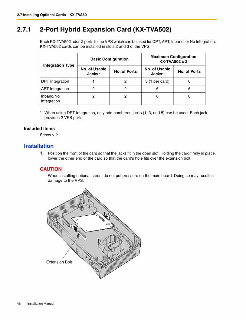
2.7.1 2-Port Hybrid Expansion Card (KX-TVA502)
Each KX-TVA502 adds 2 ports to the VPS which can be used for DPT, APT, Inband, or No Integration. KX-TVA502 cards can be installed in slots 2 and 3 of the VPS.
Included ItemsScrew × 2
Installation1. Position the front of the card so that the jacks fit in the open slot. Holding the card firmly in place,
lower the other end of the card so that the card's hole fits over the extension bolt.
CAUTIONWhen installing optional cards, do not put pressure on the main board. Doing so may result in damage to the VPS.
Integration Type
Basic ConfigurationMaximum Configuration
KX-TVA502 x 2
No. of Usable Jacks*
No. of PortsNo. of Usable
Jacks*No. of Ports
DPT Integration 1 2 3 (1 per card) 6
APT Integration 2 2 6 6
Inband/No Integration
2 2 6 6
* When using DPT Integration, only odd numbered jacks (1, 3, and 5) can be used. Each jack provides 2 VPS ports.
2
1
Extension Bolt
46 Installation Manual

2.7 Installing Optional Cards—KX-TVA50
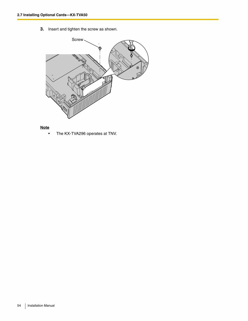
2. Insert and tighten the screws as shown.
Note
• The KX-TVA502 operates at SELV.
Screw
Installation Manual 47
2.7 Installing Optional Cards—KX-TVA50
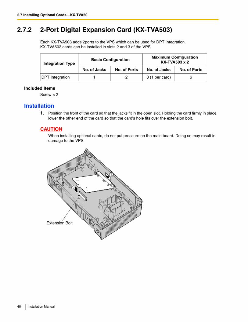
2.7.2 2-Port Digital Expansion Card (KX-TVA503)
Each KX-TVA503 adds 2ports to the VPS which can be used for DPT Integration.KX-TVA503 cards can be installed in slots 2 and 3 of the VPS.
Included ItemsScrew × 2
Installation1. Position the front of the card so that the jacks fit in the open slot. Holding the card firmly in place,
lower the other end of the card so that the card's hole fits over the extension bolt.
CAUTIONWhen installing optional cards, do not put pressure on the main board. Doing so may result in damage to the VPS.
Integration TypeBasic Configuration
Maximum ConfigurationKX-TVA503 x 2
No. of Jacks No. of Ports No. of Jacks No. of Ports
DPT Integration 1 2 3 (1 per card) 6
2
1
Extension Bolt
48 Installation Manual
2.7 Installing Optional Cards—KX-TVA50
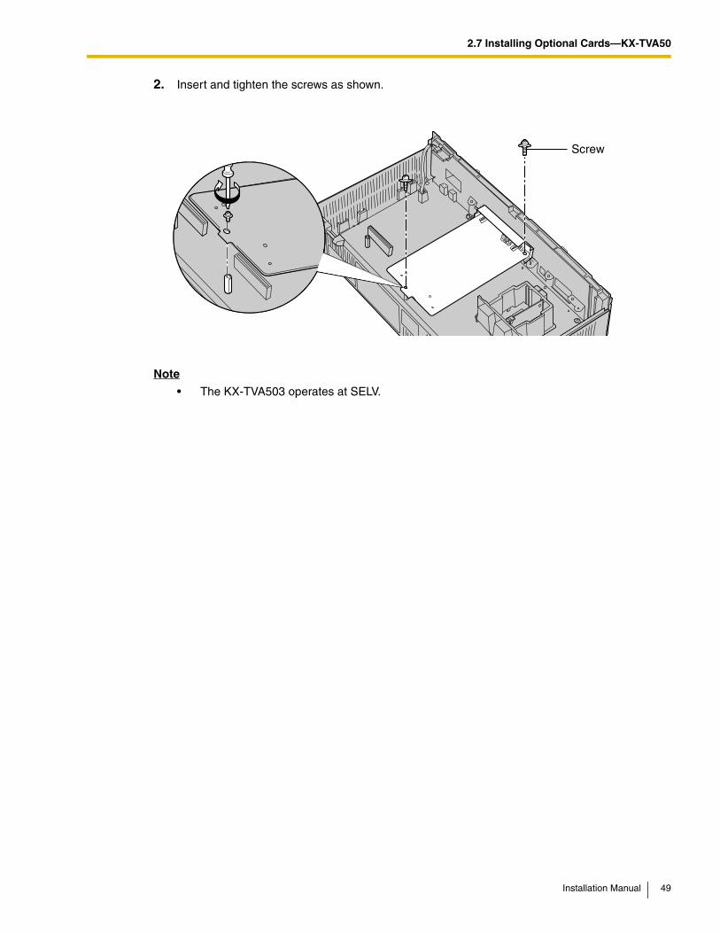
2. Insert and tighten the screws as shown.
Note
• The KX-TVA503 operates at SELV.
Screw
Installation Manual 49
2.7 Installing Optional Cards—KX-TVA50
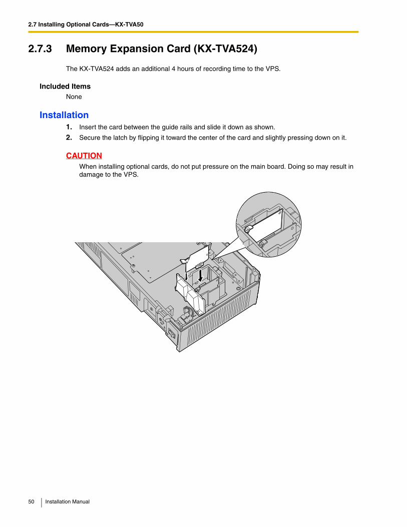
2.7.3 Memory Expansion Card (KX-TVA524)
The KX-TVA524 adds an additional 4 hours of recording time to the VPS.
Included ItemsNone
Installation1. Insert the card between the guide rails and slide it down as shown.
2. Secure the latch by flipping it toward the center of the card and slightly pressing down on it.
CAUTIONWhen installing optional cards, do not put pressure on the main board. Doing so may result in damage to the VPS.
50 Installation Manual
2.7 Installing Optional Cards—KX-TVA50
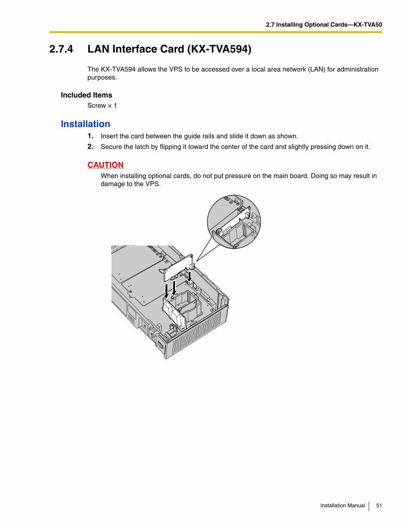
2.7.4 LAN Interface Card (KX-TVA594)
The KX-TVA594 allows the VPS to be accessed over a local area network (LAN) for administration purposes.
Included ItemsScrew × 1
Installation1. Insert the card between the guide rails and slide it down as shown.
2. Secure the latch by flipping it toward the center of the card and slightly pressing down on it.
CAUTIONWhen installing optional cards, do not put pressure on the main board. Doing so may result in damage to the VPS.
Installation Manual 51
2.7 Installing Optional Cards—KX-TVA50
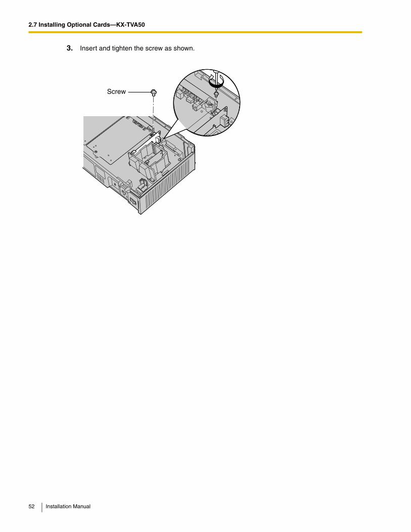
3. Insert and tighten the screw as shown.
Screw
52 Installation Manual
2.7 Installing Optional Cards—KX-TVA50
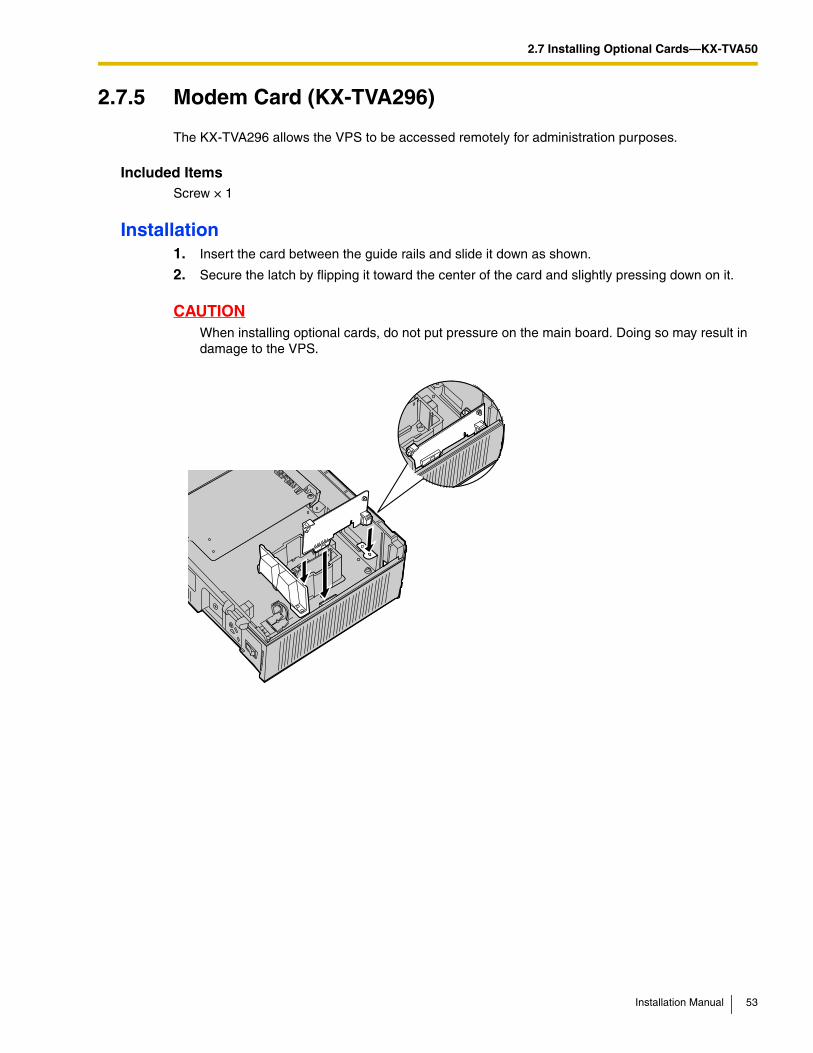
2.7.5 Modem Card (KX-TVA296)
The KX-TVA296 allows the VPS to be accessed remotely for administration purposes.
Included ItemsScrew × 1
Installation1. Insert the card between the guide rails and slide it down as shown.
2. Secure the latch by flipping it toward the center of the card and slightly pressing down on it.
CAUTIONWhen installing optional cards, do not put pressure on the main board. Doing so may result in damage to the VPS.
Installation Manual 53
2.7 Installing Optional Cards—KX-TVA50
3. Insert and tighten the screw as shown.
Note
• The KX-TVA296 operates at TNV.
Screw
54 Installation Manual
2.8 Installing Optional Cards—KX-TVA200
2.8 Installing Optional Cards—KX-TVA200The KX-TVA200 can be expanded by installing the following optional cards.
CAUTIONBefore installing optional cards, it is very important that the power to the unit be turned off. Before touching the optional cards or any components within the unit, discharge any static electricity from your body by touching the ground terminal (if it is connected to ground) or by using an grounding strap (user-supplied). This is a critical step that must be performed to protect the circuit board and other components from damage caused by static electricity.
Model Model Name Maximum Quantity
KX-TVA204 4-Port Digital Expansion Card 5
KX-TVA296 Modem Card 1
Installation Manual 55
2.8 Installing Optional Cards—KX-TVA200
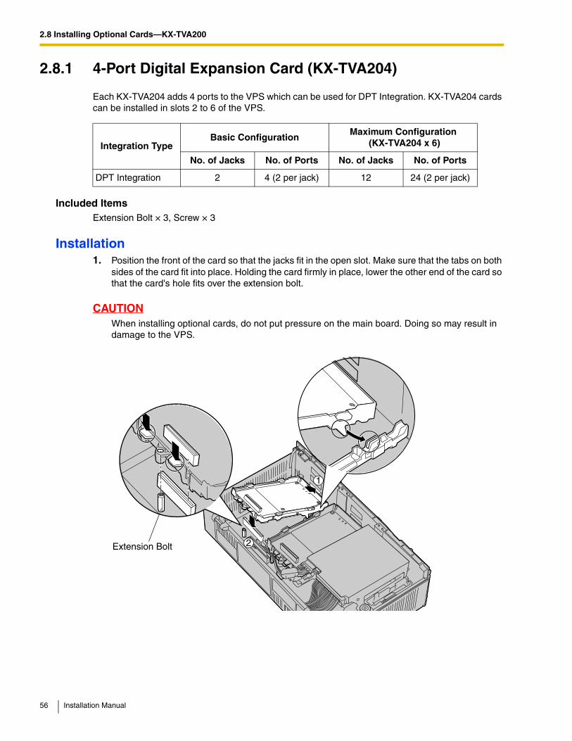
2.8.1 4-Port Digital Expansion Card (KX-TVA204)
Each KX-TVA204 adds 4 ports to the VPS which can be used for DPT Integration. KX-TVA204 cards can be installed in slots 2 to 6 of the VPS.
Included ItemsExtension Bolt × 3, Screw × 3
Installation1. Position the front of the card so that the jacks fit in the open slot. Make sure that the tabs on both
sides of the card fit into place. Holding the card firmly in place, lower the other end of the card so that the card's hole fits over the extension bolt.
CAUTIONWhen installing optional cards, do not put pressure on the main board. Doing so may result in damage to the VPS.
Integration TypeBasic Configuration
Maximum Configuration (KX-TVA204 x 6)
No. of Jacks No. of Ports No. of Jacks No. of Ports
DPT Integration 2 4 (2 per jack) 12 24 (2 per jack)
Extension Bolt
1
2
56 Installation Manual
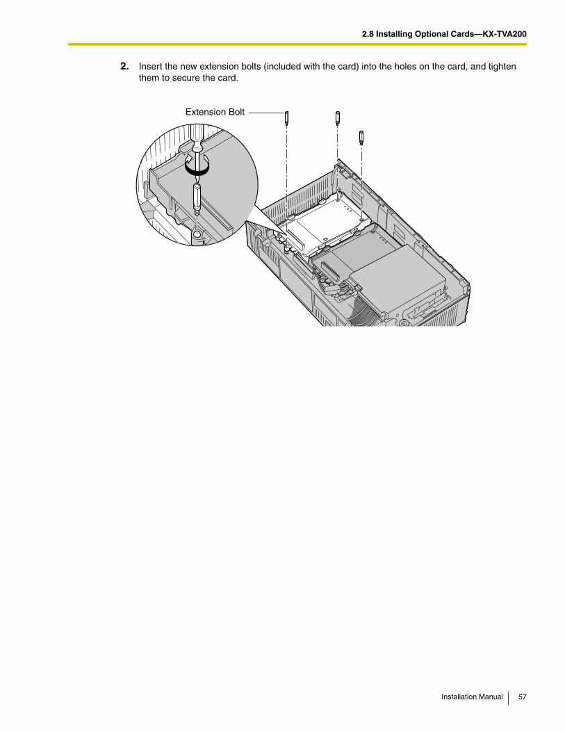
2.8 Installing Optional Cards—KX-TVA200
2. Insert the new extension bolts (included with the card) into the holes on the card, and tighten them to secure the card.
Extension Bolt
Installation Manual 57
2.8 Installing Optional Cards—KX-TVA200
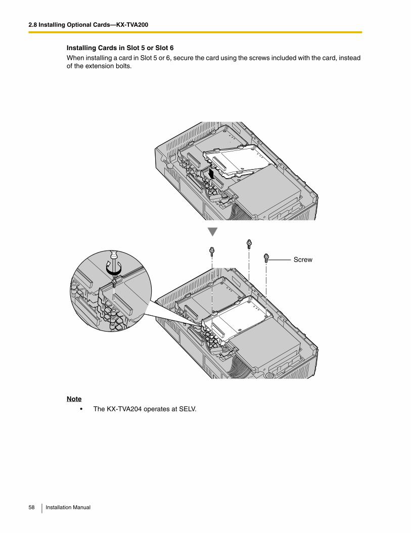
Installing Cards in Slot 5 or Slot 6
When installing a card in Slot 5 or 6, secure the card using the screws included with the card, instead of the extension bolts.
Note
• The KX-TVA204 operates at SELV.
Screw
58 Installation Manual
2.8 Installing Optional Cards—KX-TVA200
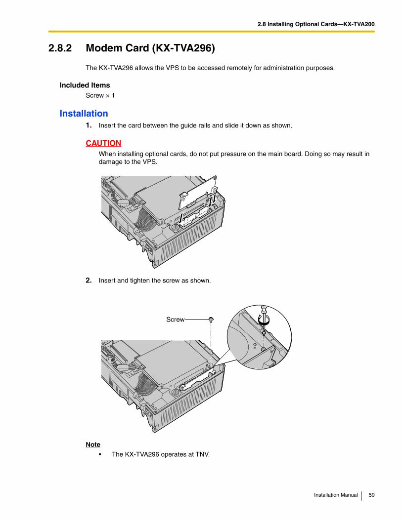
2.8.2 Modem Card (KX-TVA296)
The KX-TVA296 allows the VPS to be accessed remotely for administration purposes.
Included ItemsScrew × 1
Installation1. Insert the card between the guide rails and slide it down as shown.
CAUTIONWhen installing optional cards, do not put pressure on the main board. Doing so may result in damage to the VPS.
2. Insert and tighten the screw as shown.
Note
• The KX-TVA296 operates at TNV.
Screw
Installation Manual 59
2.9 PBX Connections
2.9 PBX Connections
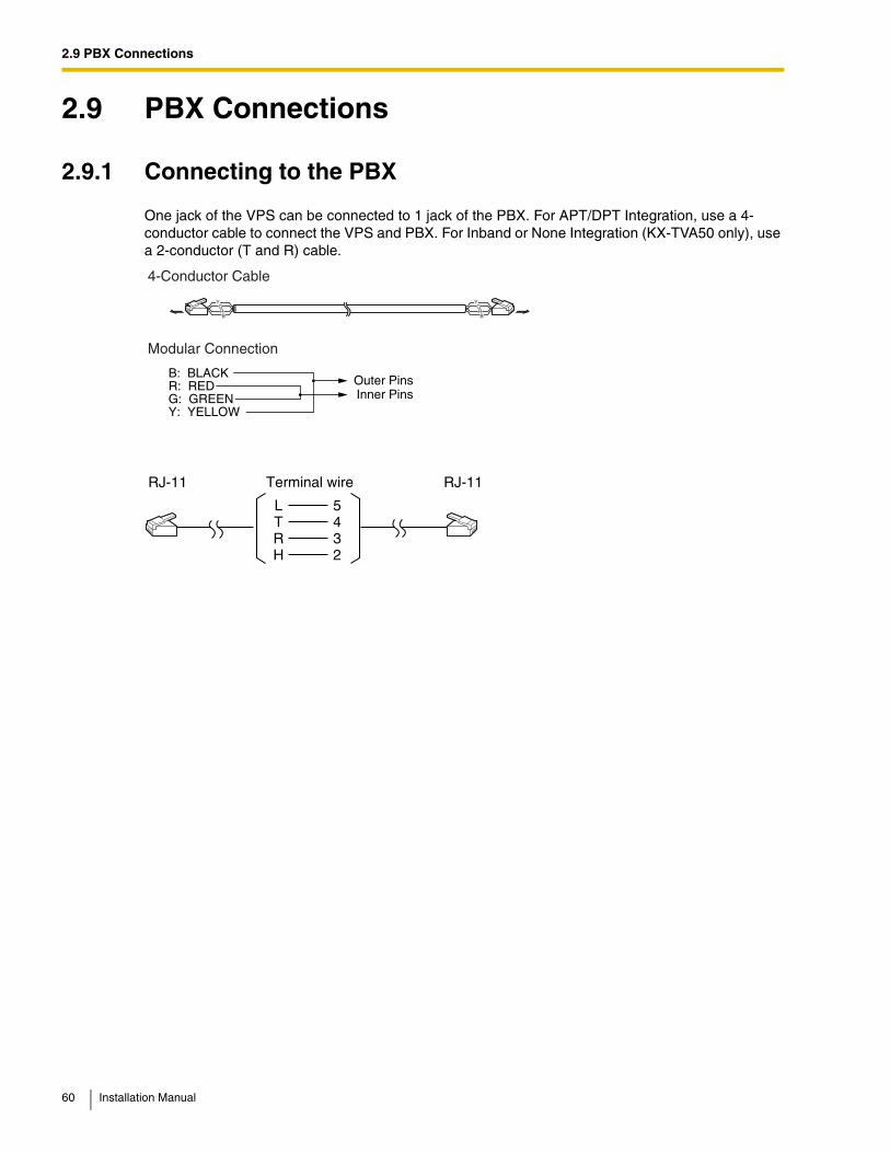
2.9.1 Connecting to the PBX
One jack of the VPS can be connected to 1 jack of the PBX. For APT/DPT Integration, use a 4-conductor cable to connect the VPS and PBX. For Inband or None Integration (KX-TVA50 only), use a 2-conductor (T and R) cable.
YGRB
YGRB
4-Conductor Cable
Modular Connection
Outer PinsInner Pins
B: BLACKR: REDG: GREENY: YELLOW
L 5
Terminal wireRJ-11
T 4R 3H 2
RJ-11
60 Installation Manual
2.9 PBX Connections
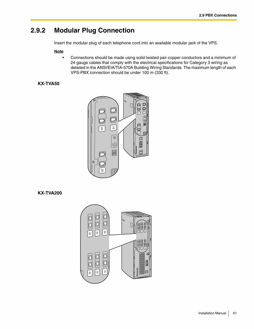
2.9.2 Modular Plug Connection
Insert the modular plug of each telephone cord into an available modular jack of the VPS.
Note
• Connections should be made using solid twisted pair copper conductors and a minimum of 24 gauge cables that comply with the electrical specifications for Category 3 wiring as detailed in the ANSI/EIA/TIA-570A Building Wiring Standards. The maximum length of each VPS-PBX connection should be under 100 m (330 ft).
KX-TVA50
KX-TVA200
01
0203
01
0203
0102
0304
0506
0102
0304
0506
Installation Manual 61
2.10 PC Connection
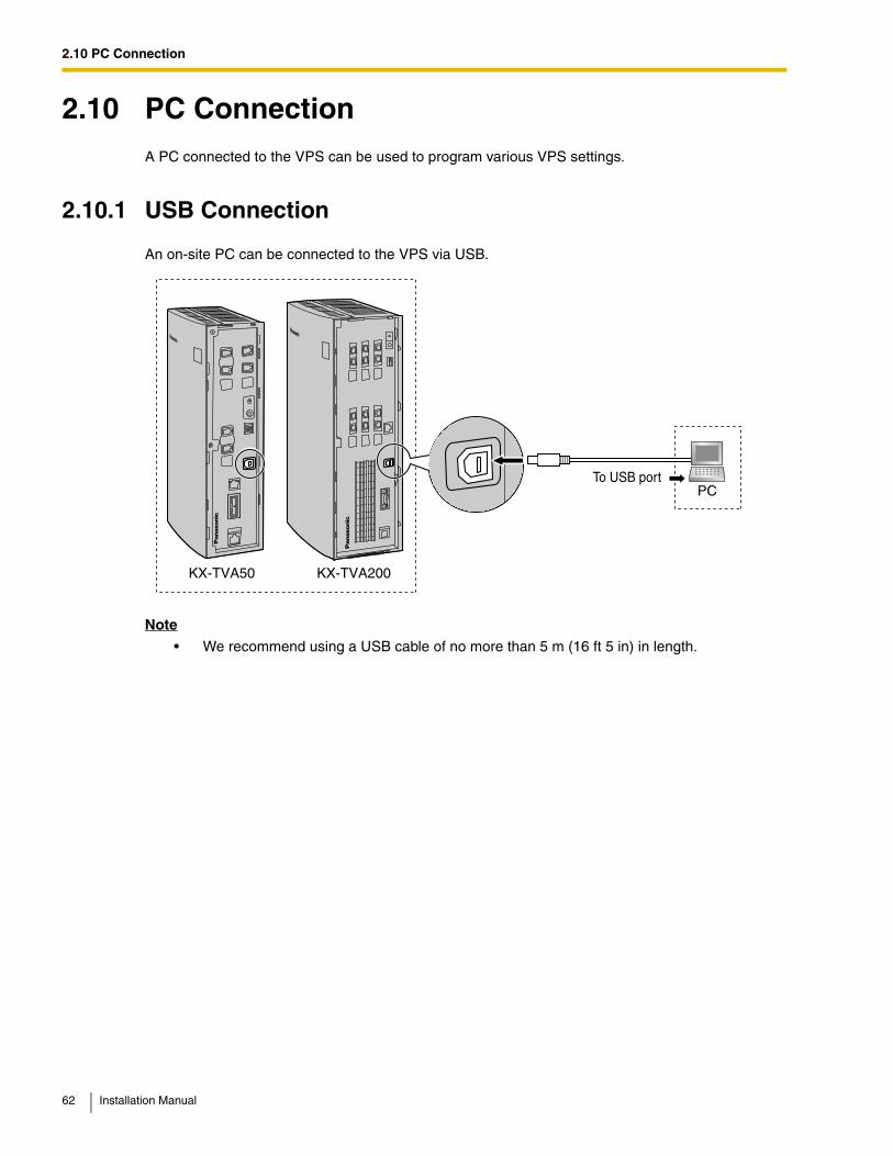
2.10 PC ConnectionA PC connected to the VPS can be used to program various VPS settings.
2.10.1 USB Connection
An on-site PC can be connected to the VPS via USB.
Note
• We recommend using a USB cable of no more than 5 m (16 ft 5 in) in length.
PCTo USB port
KX-TVA200KX-TVA50
62 Installation Manual
2.10 PC Connection
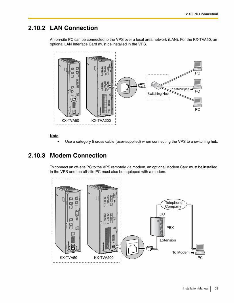
2.10.2 LAN Connection
An on-site PC can be connected to the VPS over a local area network (LAN). For the KX-TVA50, an optional LAN Interface Card must be installed in the VPS.
Note
• Use a category 5 cross cable (user-supplied) when connecting the VPS to a switching hub.
2.10.3 Modem Connection
To connect an off-site PC to the VPS remotely via modem, an optional Modem Card must be installed in the VPS and the off-site PC must also be equipped with a modem.
To network port
Switching Hub
PC
PC
PC
KX-TVA200KX-TVA50
To Modem
CO
Extension
TelephoneCompany
PC
PBX
KX-TVA200KX-TVA50
Installation Manual 63
2.10 PC Connection
Note
• Do not connect the modem directly to the network. Connect the modem to the PBX as you would a standard single line telephone (SLT). Off-site programming is possible if trunk (CO line) calls from the remote PC are routed to the extension port connected to the VPS modem. Note that the effective data transfer rate of the internal modem (maximum 33 600 bps) will be subject to the throughput limitations of the PBX.
64 Installation Manual
2.11 Frame Ground Connection
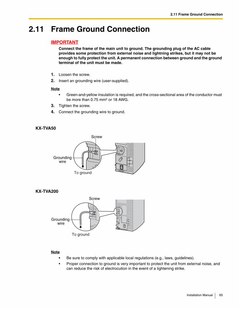
2.11 Frame Ground Connection
IMPORTANTConnect the frame of the main unit to ground. The grounding plug of the AC cable provides some protection from external noise and lightning strikes, but it may not be enough to fully protect the unit. A permanent connection between ground and the ground terminal of the unit must be made.
1. Loosen the screw.
2. Insert an grounding wire (user-supplied).
Note
• Green-and-yellow insulation is required, and the cross-sectional area of the conductor must be more than 0.75 mm2 or 18 AWG.
3. Tighten the screw.
4. Connect the grounding wire to ground.
KX-TVA50
KX-TVA200
Note
• Be sure to comply with applicable local regulations (e.g., laws, guidelines).
• Proper connection to ground is very important to protect the unit from external noise, and can reduce the risk of electrocution in the event of a lightening strike.
Screw
Groundingwire
To ground
Screw
Groundingwire
To ground
Installation Manual 65
2.12 Connecting the AC Adaptor
2.12 Connecting the AC Adaptor
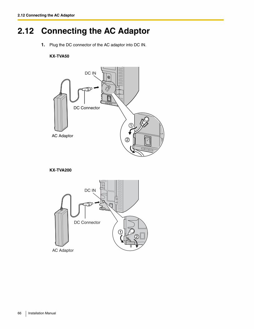
1. Plug the DC connector of the AC adaptor into DC IN.
KX-TVA50
KX-TVA200
AC Adaptor
DC Connector
DC IN
2
1
AC Adaptor
DC Connector
DC IN
21
66 Installation Manual
2.12 Connecting the AC Adaptor
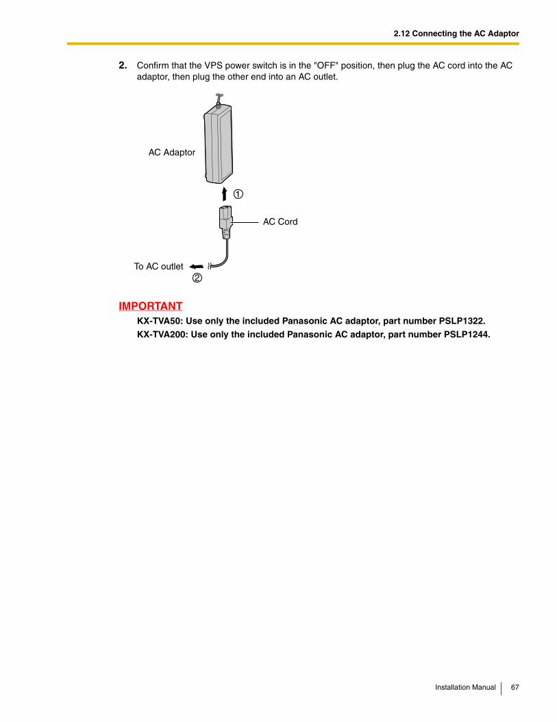
2. Confirm that the VPS power switch is in the "OFF" position, then plug the AC cord into the AC adaptor, then plug the other end into an AC outlet.
IMPORTANTKX-TVA50: Use only the included Panasonic AC adaptor, part number PSLP1322.
KX-TVA200: Use only the included Panasonic AC adaptor, part number PSLP1244.
AC Adaptor
AC Cord
To AC outlet
Installation Manual 67
2.13 Securing the Cables
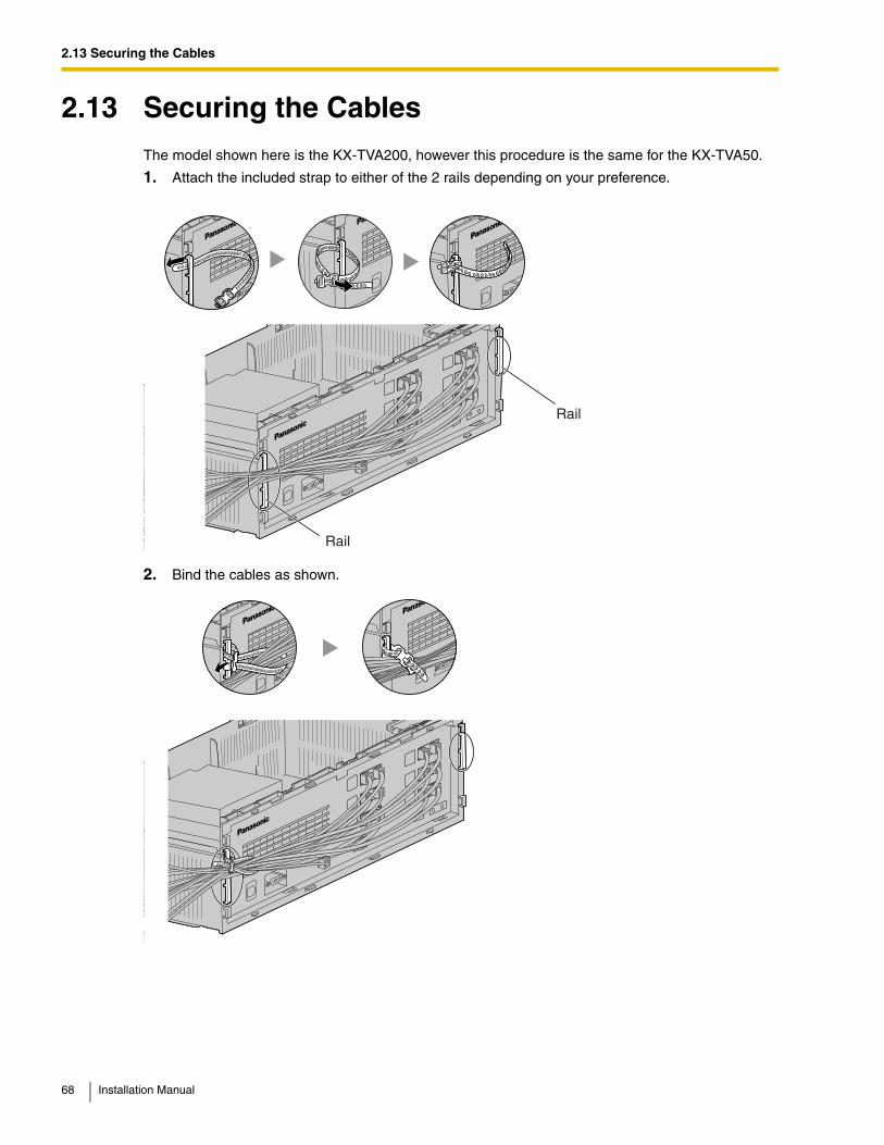
2.13 Securing the CablesThe model shown here is the KX-TVA200, however this procedure is the same for the KX-TVA50.
1. Attach the included strap to either of the 2 rails depending on your preference.
2. Bind the cables as shown.
Rail
Rail
68 Installation Manual
2.13 Securing the Cables
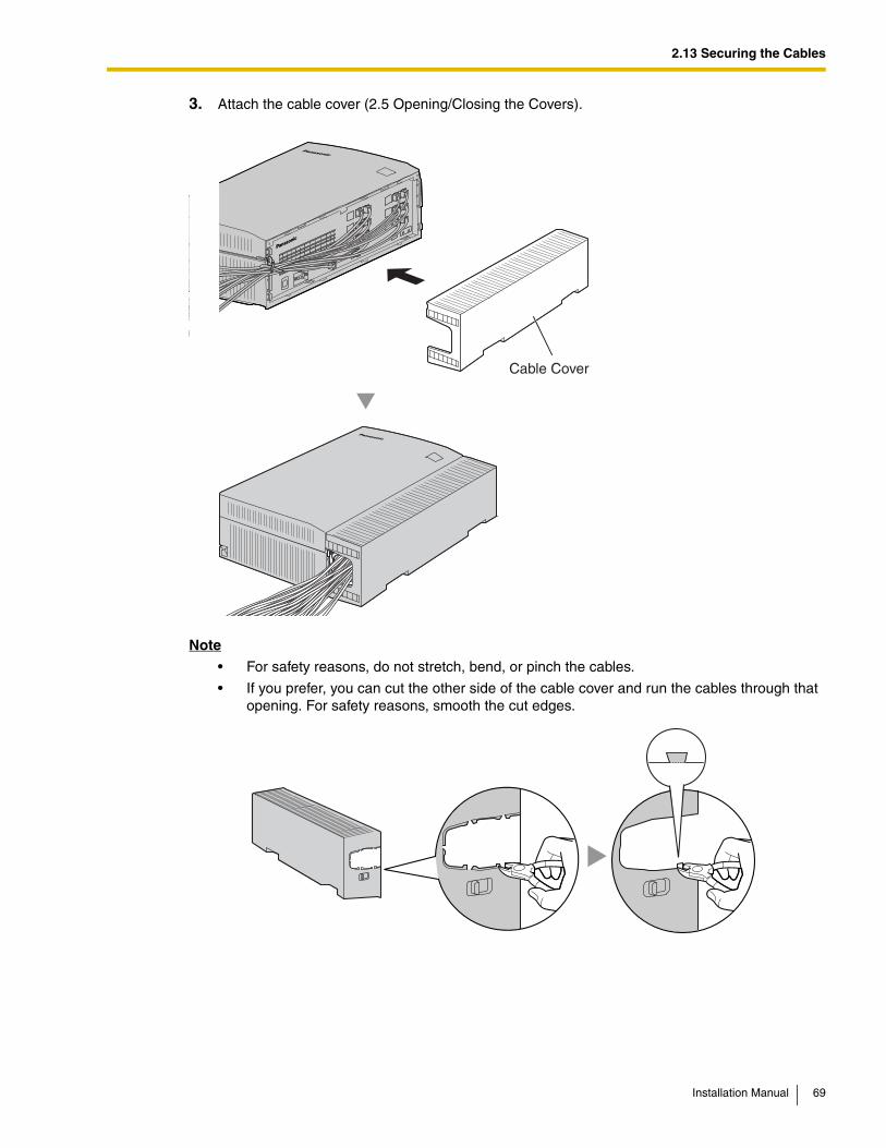
3. Attach the cable cover (2.5 Opening/Closing the Covers).
Note
• For safety reasons, do not stretch, bend, or pinch the cables.
• If you prefer, you can cut the other side of the cable cover and run the cables through that opening. For safety reasons, smooth the cut edges.
Cable Cover
Installation Manual 69
2.14 Initializing the VPS During Installation
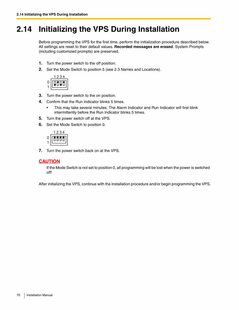
2.14 Initializing the VPS During InstallationBefore programming the VPS for the first time, perform the initialization procedure described below. All settings are reset to their default values. Recorded messages are erased. System Prompts (including customized prompts) are preserved.
1. Turn the power switch to the off position.
2. Set the Mode Switch to position 5 (see 2.3 Names and Locations).
3. Turn the power switch to the on position.
4. Confirm that the Run Indicator blinks 5 times.
• This may take several minutes. The Alarm Indicator and Run Indicator will first blink intermittently before the Run Indicator blinks 5 times.
5. Turn the power switch off at the VPS.
6. Set the Mode Switch to position 0.
7. Turn the power switch back on at the VPS.
CAUTIONIf the Mode Switch is not set to position 0, all programming will be lost when the power is switched off!
After initializing the VPS, continue with the installation procedure and/or begin programming the VPS.
01
1 2 3 4
01
1 2 3 4
70 Installation Manual
2.15 Wall Mounting
2.15 Wall Mounting
2.15.1 Wall Mounting the VPS
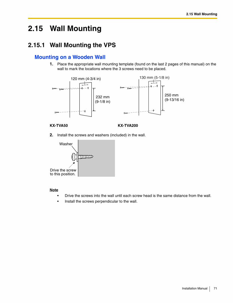
Mounting on a Wooden Wall1. Place the appropriate wall mounting template (found on the last 2 pages of this manual) on the
wall to mark the locations where the 3 screws need to be placed.
2. Install the screws and washers (included) in the wall.
Note
• Drive the screws into the wall until each screw head is the same distance from the wall.
• Install the screws perpendicular to the wall.
KX-TVA50 KX-TVA200
232 mm(9-1/8 in)
120 mm (4-3/4 in)
250 mm(9-13/16 in)
130 mm (5-1/8 in)
Washer
Drive the screwto this position.
Installation Manual 71
2.15 Wall Mounting
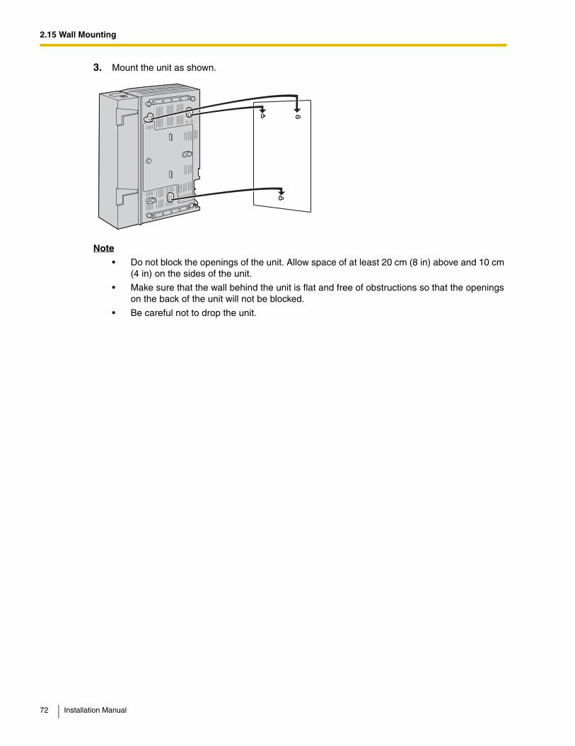
3. Mount the unit as shown.
Note
• Do not block the openings of the unit. Allow space of at least 20 cm (8 in) above and 10 cm (4 in) on the sides of the unit.
• Make sure that the wall behind the unit is flat and free of obstructions so that the openings on the back of the unit will not be blocked.
• Be careful not to drop the unit.
72 Installation Manual
2.15 Wall Mounting
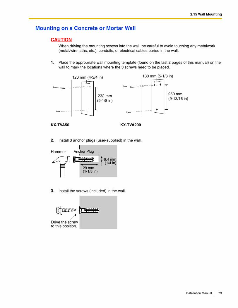
Mounting on a Concrete or Mortar Wall
CAUTIONWhen driving the mounting screws into the wall, be careful to avoid touching any metalwork (metal/wire laths, etc.), conduits, or electrical cables buried in the wall.
1. Place the appropriate wall mounting template (found on the last 2 pages of this manual) on the wall to mark the locations where the 3 screws need to be placed.
2. Install 3 anchor plugs (user-supplied) in the wall.
3. Install the screws (included) in the wall.
KX-TVA50 KX-TVA200
232 mm(9-1/8 in)
120 mm (4-3/4 in)
250 mm(9-13/16 in)
130 mm (5-1/8 in)
Hammer
29 mm(1-1/8 in)
Anchor Plug
6.4 mm (1/4 in)
Drive the screwto this position.
Installation Manual 73

2.15 Wall Mounting
4. Mount the unit as shown.
Note
• Do not block the openings of the unit. Allow space of at least 20 cm (8 in) above and 10 cm (4 in) on the sides of the unit.
• Make sure that the wall behind the unit is flat and free of obstructions so that the openings on the back of the unit will not be blocked.
• Be careful not to drop the unit.
74 Installation Manual
2.15 Wall Mounting
2.15.2 Wall Mounting the AC Adaptor
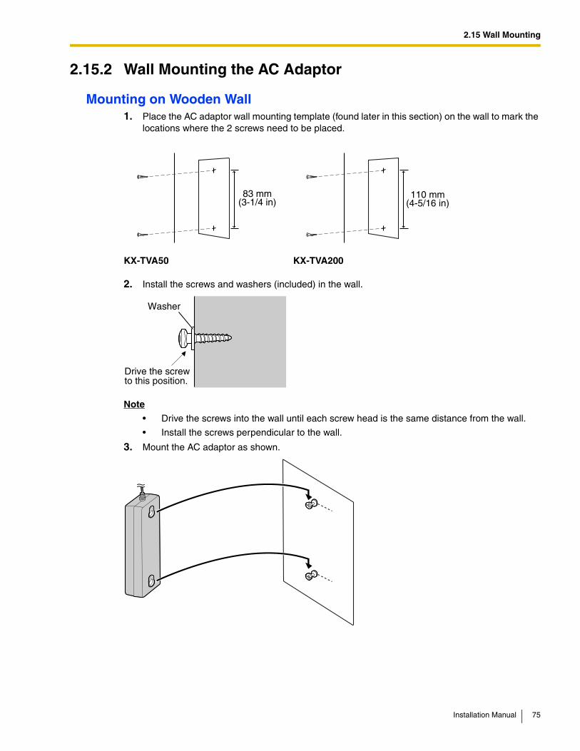
Mounting on Wooden Wall1. Place the AC adaptor wall mounting template (found later in this section) on the wall to mark the
locations where the 2 screws need to be placed.
2. Install the screws and washers (included) in the wall.
Note
• Drive the screws into the wall until each screw head is the same distance from the wall.
• Install the screws perpendicular to the wall.
3. Mount the AC adaptor as shown.
KX-TVA50 KX-TVA200
83 mm(3-1/4 in)
110 mm(4-5/16 in)
Washer
Drive the screwto this position.
Installation Manual 75
2.15 Wall Mounting
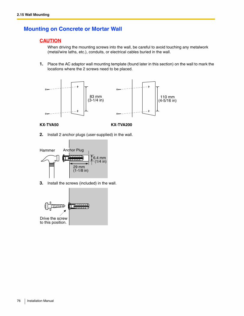
Mounting on Concrete or Mortar Wall
CAUTIONWhen driving the mounting screws into the wall, be careful to avoid touching any metalwork (metal/wire laths, etc.), conduits, or electrical cables buried in the wall.
1. Place the AC adaptor wall mounting template (found later in this section) on the wall to mark the locations where the 2 screws need to be placed.
2. Install 2 anchor plugs (user-supplied) in the wall.
3. Install the screws (included) in the wall.
KX-TVA50 KX-TVA200
83 mm(3-1/4 in)
110 mm(4-5/16 in)
Hammer
29 mm(1-1/8 in)
Anchor Plug
6.4 mm (1/4 in)
Drive the screwto this position.
76 Installation Manual
2.15 Wall Mounting
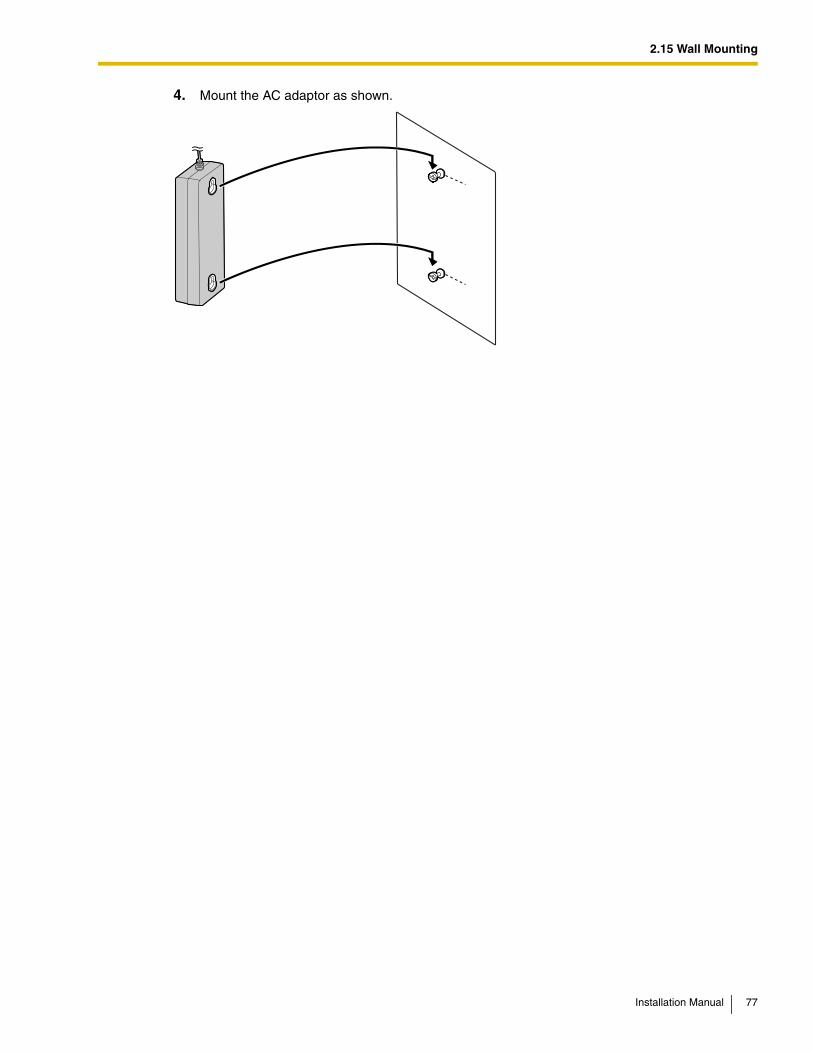
4. Mount the AC adaptor as shown.
Installation Manual 77
2.15 Wall Mounting
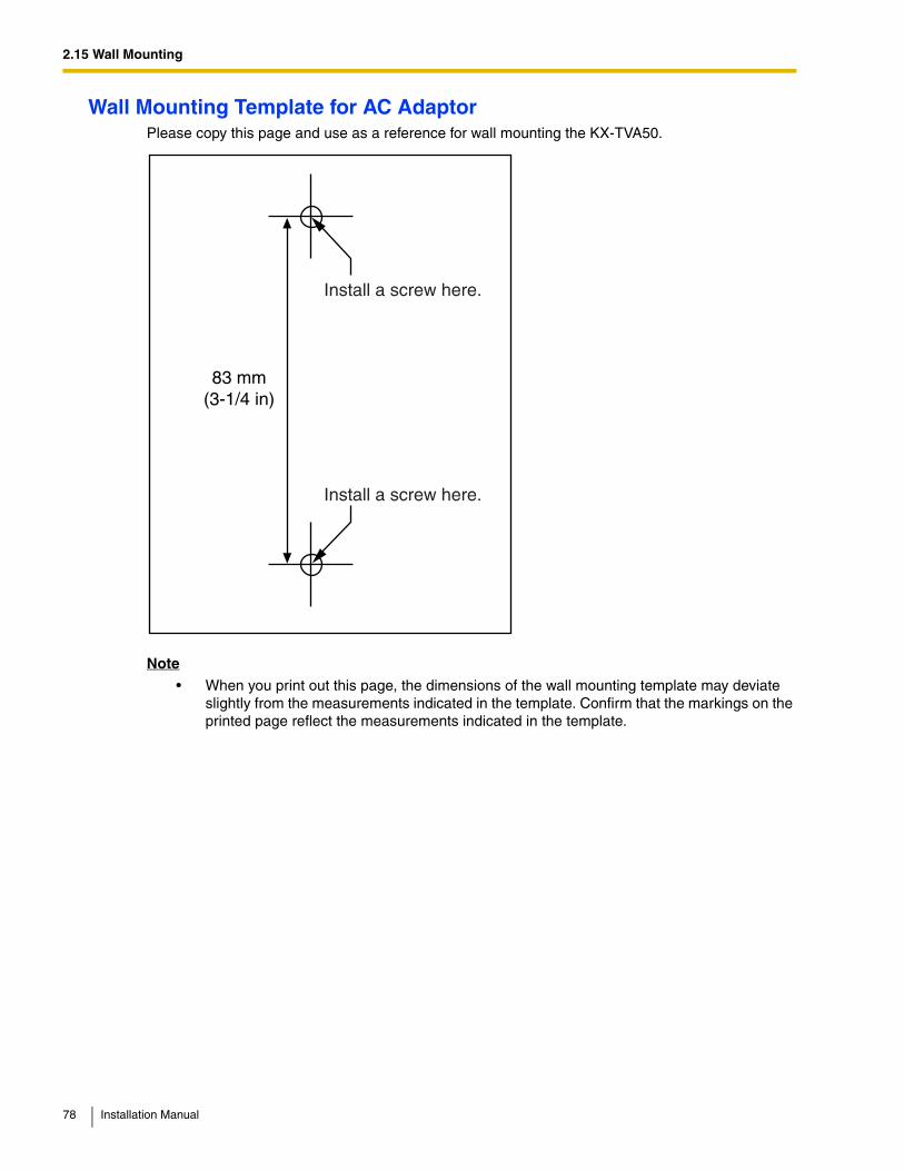
Wall Mounting Template for AC AdaptorPlease copy this page and use as a reference for wall mounting the KX-TVA50.
Note
• When you print out this page, the dimensions of the wall mounting template may deviate slightly from the measurements indicated in the template. Confirm that the markings on the printed page reflect the measurements indicated in the template.
83 mm(3-1/4 in)
Install a screw here.
Install a screw here.
78 Installation Manual
2.15 Wall Mounting
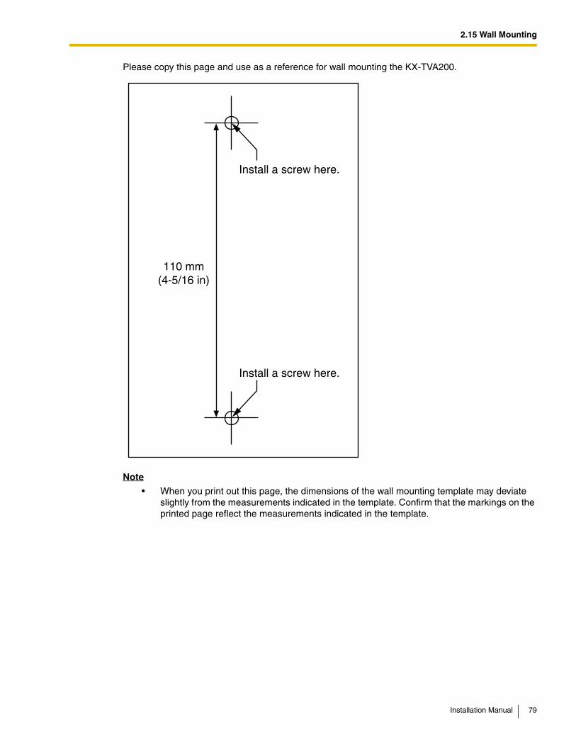
Please copy this page and use as a reference for wall mounting the KX-TVA200.
Note
• When you print out this page, the dimensions of the wall mounting template may deviate slightly from the measurements indicated in the template. Confirm that the markings on the printed page reflect the measurements indicated in the template.
Install a screw here.
Install a screw here.
110 mm(4-5/16 in)
Installation Manual 79

2.15 Wall Mounting
80 Installation Manual

Section 3
Installing KX-TVA Maintenance Console
This section explains how to install KX-TVA Maintenance Console on a PC.
Installation Manual 81
3.1 Overview
3.1 OverviewAfter wall mounting and connecting the VPS to the PBX, you can begin programming the VPS. This programming should be performed by the installer, using the KX-TVA Maintenance Console software. This software can be used to set system parameters, change system prompts, diagnose system functions, etc.KX-TVA Maintenance Console supports connection to the VPS via USB, LAN, and modem. For details on how to connect the PC to the VPS, see 2.9 PBX Connections. For detailed information on all programming parameters available through KX-TVA Maintenance Console, refer to the Programming Manual or the software's on-line Help feature.This section explains how to install the software on a PC. Normally you should install the software KX-TVA Maintenance Console on a PC that will be on-site with you during initial programming.
82 Installation Manual
3.2 KX-TVA Maintenance Console Installation
3.2 KX-TVA Maintenance Console Installation
System RequirementsRequired Operating System
Microsoft Windows 98 SE, Windows 2000, Windows Me, or Windows XP
Minimum Hardware Requirements
CPU: 133 MHz Intel Pentium microprocessor
HDD: 300 MB of available hard disk space
RAM: 64 MB of available RAM (128 MB recommended)
Password SecurityTo maintain system security, a password is required to perform system programming. We recommend changing the default password the first time you access the VPS via KX-TVA Maintenance Console. The default password can be changed by running the Quick Setup utility (see 6.1.2 Quick Setup) or by selecting System Security Administrator Password.
Warning to the Administrator regarding the system password
1. To avoid unauthorized access to VPS settings, which could result in fraudulent dialing, do not disclose the password.
2. Please inform the customer of the importance of the password and the possible dangers if it becomes known to others.
3. Please change the password periodically.
4. To prevent unauthorized access, we strongly recommend selecting a long and random password.
5. If the system password is forgotten, you have to reset the VPS to its factory defaults and reprogram it.
Note
• A Programmer Code, if set, is required to start KX-TVA Maintenance Console. You can set or delete the Programmer Code by selecting Utility Programmer Code. If no code is set, the KX-TVA Maintenance Console can be started and used, but a password is required to connect to the VPS and change VPS settings.
® ®
® ®
Installation Manual 83
3.2 KX-TVA Maintenance Console Installation
Installing KX-TVA Maintenance Console
Note
• To install or uninstall the software on a PC running Windows 2000 Professional or Windows XP Professional, you must be logged in as a user that is in either the "Administrators" or "Power Users" group.
• When the VPS is first connected to the PC via USB, a wizard should appear and ask you to select the appropriate USB driver. Browse for and select the KX-TVA USB driver, which is copied to the local drive during installation.
Updating other Panasonic Drivers
CAUTIONInstalling the USB driver may prevent the USB driver for KX-TDA series or PC Console/Phone Software from functioning correctly. In this case, update the USB drivers as necessary from the following folders on the included CD-ROM:KX-TDA Series: CD-ROM Drive:\TDA_USB Driver\TDA_USB DriverPC Console/Phone Software: CD-ROM Drive:\TDA_USB Driver\T7601_USB Driver
Note
• Before installing or uninstalling the driver, be sure to close any open applications.
Windows 98SE
1. Connect the PC to the PBX with a USB cable. The Add New Hardware Wizard will appear.
2. Click Next.
3. Select Search for the best driver for your device. [Recommended], then click Next.
4. Select Specify a location, then click Browse.
5. Specify the folder containing the USB driver, CD-ROM Drive:\USB driver\Win98, then click OK.
6. Click Next.
7. Click Next.
8. Click Finish.
Note
• If a dialog box appears asking you to restart your PC, restart the PC.
1. Copy the KX-TVA Maintenance Console setup file to a local drive on the PC. (Its icon is shown here, on the left.)
2. Double-click the setup file to run the installer.
3. Follow the on-screen instructions provided by the installation wizard.
4. Click "Finish".
5. Click "Yes" when prompted to copy the USB drivers, specify a location, then click "OK".
6. Click "OK" after the drivers have been copied to the local drive.
84 Installation Manual
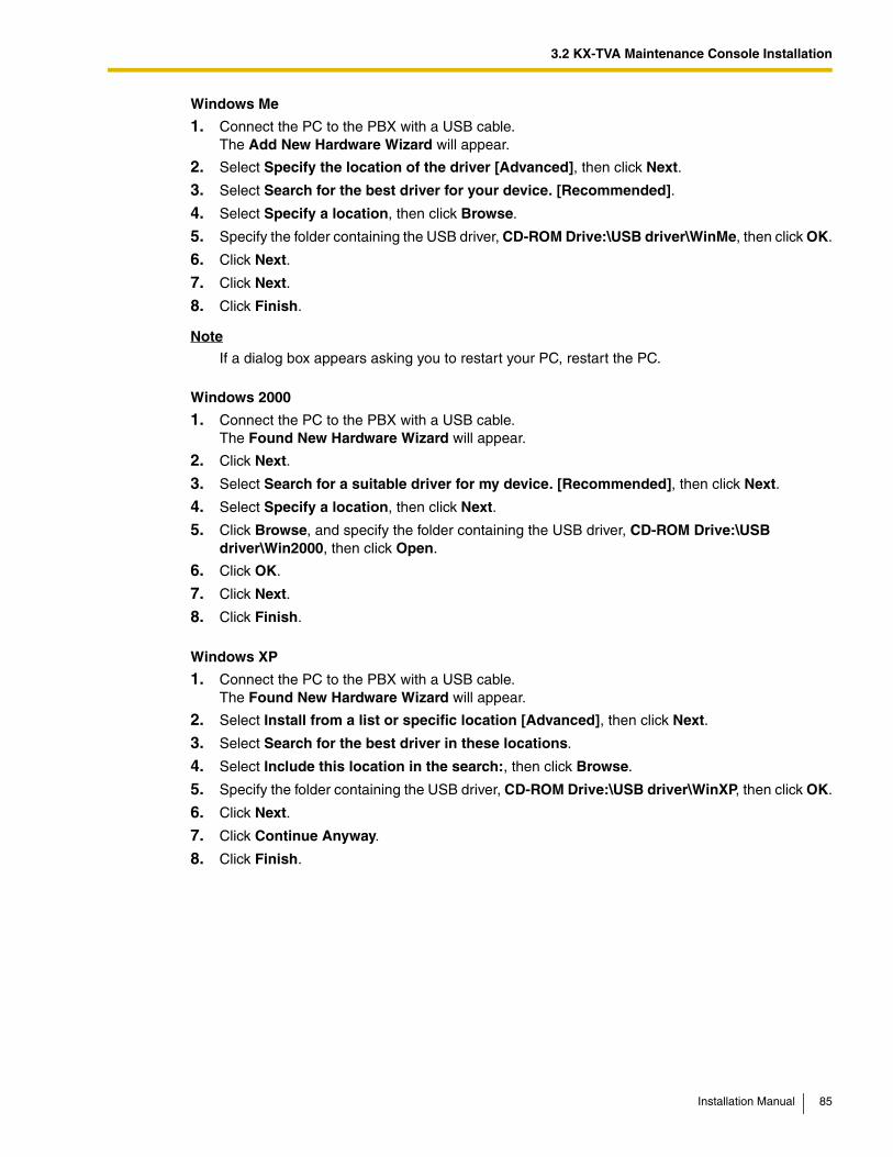
3.2 KX-TVA Maintenance Console Installation
Windows Me
1. Connect the PC to the PBX with a USB cable. The Add New Hardware Wizard will appear.
2. Select Specify the location of the driver [Advanced], then click Next.
3. Select Search for the best driver for your device. [Recommended].
4. Select Specify a location, then click Browse.
5. Specify the folder containing the USB driver, CD-ROM Drive:\USB driver\WinMe, then click OK.
6. Click Next.
7. Click Next.
8. Click Finish.
Note
If a dialog box appears asking you to restart your PC, restart the PC.
Windows 2000
1. Connect the PC to the PBX with a USB cable. The Found New Hardware Wizard will appear.
2. Click Next.
3. Select Search for a suitable driver for my device. [Recommended], then click Next.
4. Select Specify a location, then click Next.
5. Click Browse, and specify the folder containing the USB driver, CD-ROM Drive:\USB driver\Win2000, then click Open.
6. Click OK.
7. Click Next.
8. Click Finish.
Windows XP
1. Connect the PC to the PBX with a USB cable. The Found New Hardware Wizard will appear.
2. Select Install from a list or specific location [Advanced], then click Next.
3. Select Search for the best driver in these locations.
4. Select Include this location in the search:, then click Browse.
5. Specify the folder containing the USB driver, CD-ROM Drive:\USB driver\WinXP, then click OK.
6. Click Next.
7. Click Continue Anyway.
8. Click Finish.
Installation Manual 85
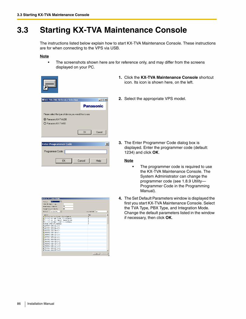
3.3 Starting KX-TVA Maintenance Console
3.3 Starting KX-TVA Maintenance ConsoleThe instructions listed below explain how to start KX-TVA Maintenance Console. These instructions are for when connecting to the VPS via USB.
Note
• The screenshots shown here are for reference only, and may differ from the screens displayed on your PC.
1. Click the KX-TVA Maintenance Console shortcut icon. Its icon is shown here, on the left.
2. Select the appropriate VPS model.
3. The Enter Programmer Code dialog box is displayed. Enter the programmer code (default: 1234) and click OK.
Note
• The programmer code is required to use the KX-TVA Maintenance Console. The System Administrator can change the programmer code (see 1.8.9 Utility—Programmer Code in the Programming Manual).
4. The Set Default Parameters window is displayed the first you start KX-TVA Maintenance Console. Select the TVA Type, PBX Type, and Integration Mode. Change the default parameters listed in the window if necessary, then click OK.
86 Installation Manual
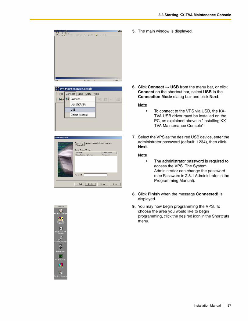
3.3 Starting KX-TVA Maintenance Console
5. The main window is displayed.
6. Click Connect → USB from the menu bar, or click Connect on the shortcut bar, select USB in the Connection Mode dialog box and click Next.
Note
• To connect to the VPS via USB, the KX-TVA USB driver must be installed on the PC, as explained above in "Installing KX-TVA Maintenance Console".
7. Select the VPS as the desired USB device, enter the administrator password (default: 1234), then click Next.
Note
• The administrator password is required to access the VPS. The System Administrator can change the password (see Password in 2.8.1 Administrator in the Programming Manual).
8. Click Finish when the message Connected! is displayed.
9. You may now begin programming the VPS. To choose the area you would like to begin programming, click the desired icon in the Shortcuts menu.
Installation Manual 87
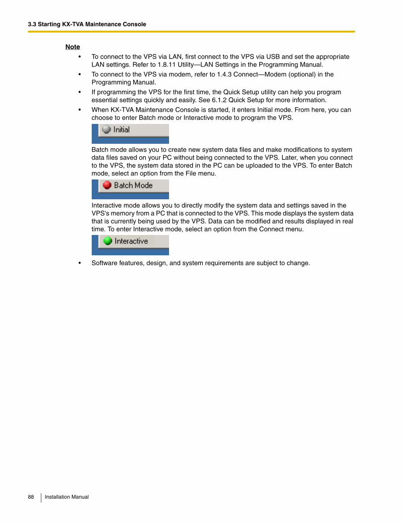
3.3 Starting KX-TVA Maintenance Console
Note
• To connect to the VPS via LAN, first connect to the VPS via USB and set the appropriate LAN settings. Refer to 1.8.11 Utility—LAN Settings in the Programming Manual.
• To connect to the VPS via modem, refer to 1.4.3 Connect—Modem (optional) in the Programming Manual.
• If programming the VPS for the first time, the Quick Setup utility can help you program essential settings quickly and easily. See 6.1.2 Quick Setup for more information.
• When KX-TVA Maintenance Console is started, it enters Initial mode. From here, you can choose to enter Batch mode or Interactive mode to program the VPS.
Batch mode allows you to create new system data files and make modifications to system data files saved on your PC without being connected to the VPS. Later, when you connect to the VPS, the system data stored in the PC can be uploaded to the VPS. To enter Batch mode, select an option from the File menu.
Interactive mode allows you to directly modify the system data and settings saved in the VPS's memory from a PC that is connected to the VPS. This mode displays the system data that is currently being used by the VPS. Data can be modified and results displayed in real time. To enter Interactive mode, select an option from the Connect menu.
• Software features, design, and system requirements are subject to change.
88 Installation Manual
Section 4
PBX Programming for APT/DPT Integration
This section explains how to configure compatible Panasonic PBXs to use APT/DPT Integration with the VPS.
Installation Manual 89
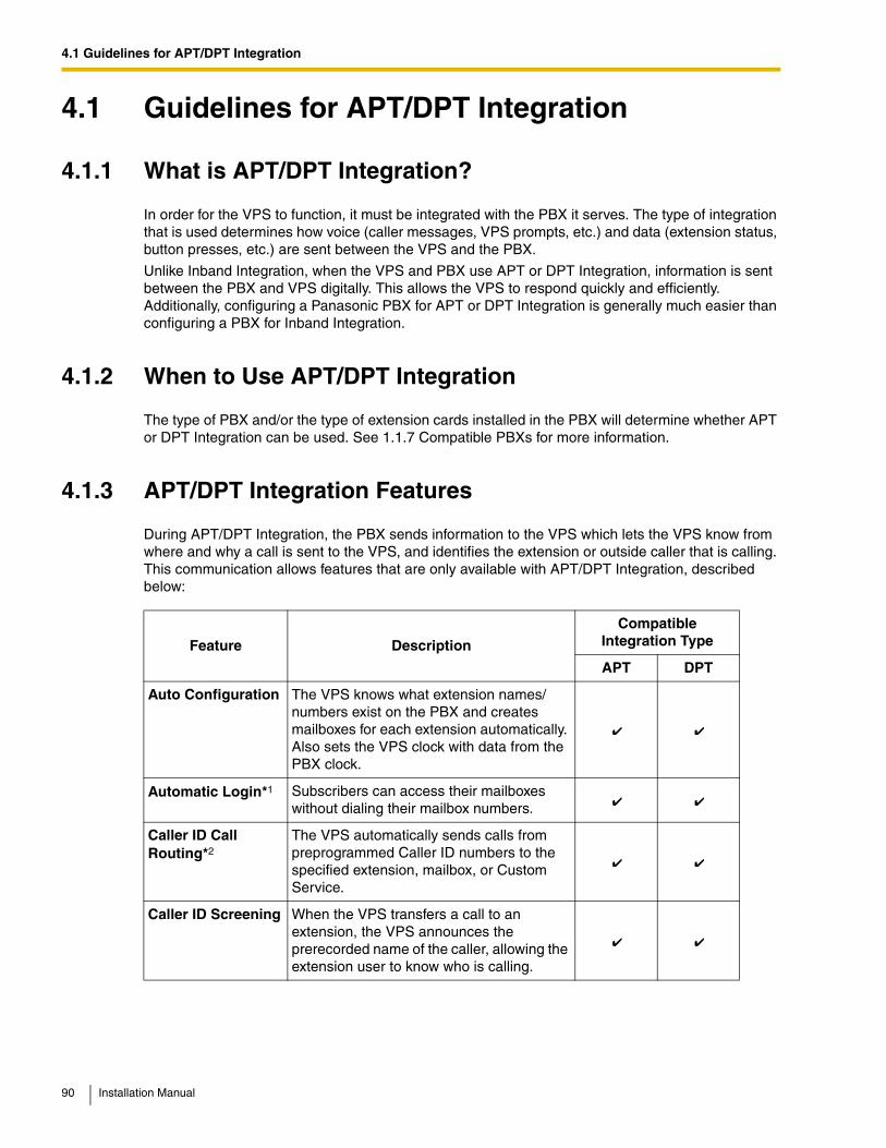
4.1 Guidelines for APT/DPT Integration
4.1 Guidelines for APT/DPT Integration
4.1.1 What is APT/DPT Integration?
In order for the VPS to function, it must be integrated with the PBX it serves. The type of integration that is used determines how voice (caller messages, VPS prompts, etc.) and data (extension status, button presses, etc.) are sent between the VPS and the PBX.
Unlike Inband Integration, when the VPS and PBX use APT or DPT Integration, information is sent between the PBX and VPS digitally. This allows the VPS to respond quickly and efficiently. Additionally, configuring a Panasonic PBX for APT or DPT Integration is generally much easier than configuring a PBX for Inband Integration.
4.1.2 When to Use APT/DPT Integration
The type of PBX and/or the type of extension cards installed in the PBX will determine whether APT or DPT Integration can be used. See 1.1.7 Compatible PBXs for more information.
4.1.3 APT/DPT Integration Features
During APT/DPT Integration, the PBX sends information to the VPS which lets the VPS know from where and why a call is sent to the VPS, and identifies the extension or outside caller that is calling. This communication allows features that are only available with APT/DPT Integration, described below:
Feature Description
Compatible Integration Type
APT DPT
Auto Configuration The VPS knows what extension names/numbers exist on the PBX and creates mailboxes for each extension automatically. Also sets the VPS clock with data from the PBX clock.
Automatic Login*1 Subscribers can access their mailboxes without dialing their mailbox numbers.
Caller ID Call Routing*2
The VPS automatically sends calls from preprogrammed Caller ID numbers to the specified extension, mailbox, or Custom Service.
Caller ID Screening When the VPS transfers a call to an extension, the VPS announces the prerecorded name of the caller, allowing the extension user to know who is calling.
90 Installation Manual
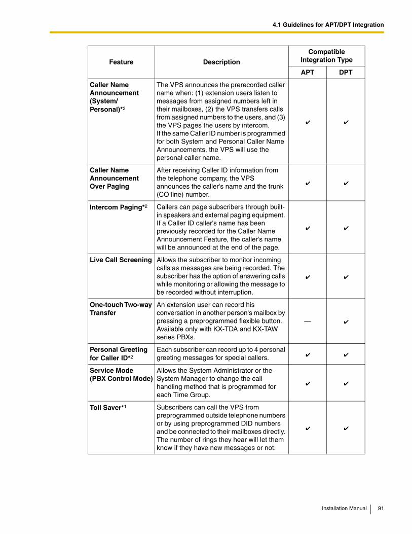
4.1 Guidelines for APT/DPT Integration
Caller Name Announcement (System/Personal)*2
The VPS announces the prerecorded caller name when: (1) extension users listen to messages from assigned numbers left in their mailboxes, (2) the VPS transfers calls from assigned numbers to the users, and (3) the VPS pages the users by intercom. If the same Caller ID number is programmed for both System and Personal Caller Name Announcements, the VPS will use the personal caller name.
Caller Name Announcement Over Paging
After receiving Caller ID information from the telephone company, the VPS announces the caller's name and the trunk (CO line) number.
Intercom Paging*2 Callers can page subscribers through built-in speakers and external paging equipment. If a Caller ID caller's name has been previously recorded for the Caller Name Announcement Feature, the caller's name will be announced at the end of the page.
Live Call Screening Allows the subscriber to monitor incoming calls as messages are being recorded. The subscriber has the option of answering calls while monitoring or allowing the message to be recorded without interruption.
One-touch Two-way Transfer
An extension user can record his conversation in another person's mailbox by pressing a preprogrammed flexible button. Available only with KX-TDA and KX-TAW series PBXs.
—
Personal Greeting for Caller ID*2
Each subscriber can record up to 4 personal greeting messages for special callers.
Service Mode (PBX Control Mode)
Allows the System Administrator or the System Manager to change the call handling method that is programmed for each Time Group.
Toll Saver*1 Subscribers can call the VPS from preprogrammed outside telephone numbers or by using preprogrammed DID numbers and be connected to their mailboxes directly. The number of rings they hear will let them know if they have new messages or not.
Feature Description
Compatible Integration Type
APT DPT
Installation Manual 91
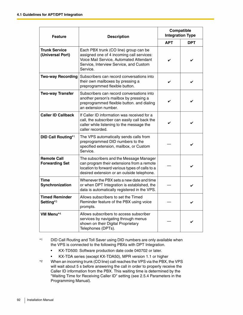
4.1 Guidelines for APT/DPT Integration
Trunk Service (Universal Port)
Each PBX trunk (CO line) group can be assigned one of 4 incoming call services: Voice Mail Service, Automated Attendant Service, Interview Service, and Custom Service.
Two-way Recording Subscribers can record conversations into their own mailboxes by pressing a preprogrammed flexible button.
Two-way Transfer Subscribers can record conversations into another person's mailbox by pressing a preprogrammed flexible button. and dialing an extension number.
Caller ID Callback If Caller ID information was received for a call, the subscriber can easily call back the caller while listening to the message the caller recorded.
DID Call Routing*1 The VPS automatically sends calls from preprogrammed DID numbers to the specified extension, mailbox, or Custom Service.
—
Remote Call Forwarding Set
The subscribers and the Message Manager can program their extensions from a remote location to forward various types of calls to a desired extension or an outside telephone.
—
Time Synchronization
Whenever the PBX sets a new date and time or when DPT Integration is established, the data is automatically registered in the VPS.
—
Timed Reminder Setting*3
Allows subscribers to set the Timed Reminder feature of the PBX using voice prompts.
—
VM Menu*4 Allows subscribers to access subscriber services by navigating through menus shown on their Digital Proprietary Telephones (DPTs).
—
*1 DID Call Routing and Toll Saver using DID numbers are only available when the VPS is connected to the following PBXs with DPT Integration.
• KX-TD500: Software production date code 040702 or later.
• KX-TDA series (except KX-TDA50), MPR version 1.1 or higher*2 When an incoming trunk (CO line) call reaches the VPS via the PBX, the VPS
will wait about 5 s before answering the call in order to properly receive the Caller ID information from the PBX. This waiting time is determined by the "Waiting Time for Receiving Caller ID" setting (see 2.5.4 Parameters in the Programming Manual).
Feature Description
Compatible Integration Type
APT DPT
92 Installation Manual
4.1 Guidelines for APT/DPT Integration
*3 Timed Reminder Setting is only available when the VPS is connected to a KX-TDA series PBX (MPR version 2.0 or higher) or KX-TAW series PBX.
*4 VM Menu is only available when the VPS is connected to a KX-TDA series PBX (MPR version 2.0 or higher).
Installation Manual 93
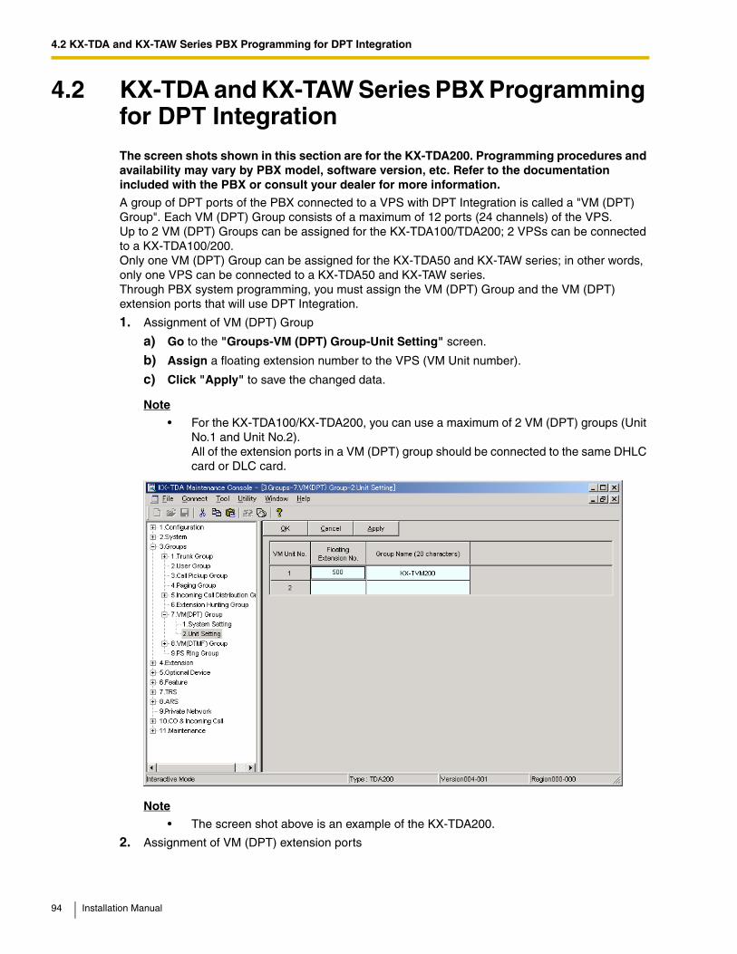
4.2 KX-TDA and KX-TAW Series PBX Programming for DPT Integration
4.2 KX-TDA and KX-TAW Series PBX Programming for DPT IntegrationThe screen shots shown in this section are for the KX-TDA200. Programming procedures and availability may vary by PBX model, software version, etc. Refer to the documentation included with the PBX or consult your dealer for more information.
A group of DPT ports of the PBX connected to a VPS with DPT Integration is called a "VM (DPT) Group". Each VM (DPT) Group consists of a maximum of 12 ports (24 channels) of the VPS. Up to 2 VM (DPT) Groups can be assigned for the KX-TDA100/TDA200; 2 VPSs can be connected to a KX-TDA100/200. Only one VM (DPT) Group can be assigned for the KX-TDA50 and KX-TAW series; in other words, only one VPS can be connected to a KX-TDA50 and KX-TAW series. Through PBX system programming, you must assign the VM (DPT) Group and the VM (DPT) extension ports that will use DPT Integration.
1. Assignment of VM (DPT) Group
a) Go to the "Groups-VM (DPT) Group-Unit Setting" screen.
b) Assign a floating extension number to the VPS (VM Unit number).
c) Click "Apply" to save the changed data.
Note
• For the KX-TDA100/KX-TDA200, you can use a maximum of 2 VM (DPT) groups (Unit No.1 and Unit No.2). All of the extension ports in a VM (DPT) group should be connected to the same DHLC card or DLC card.
Note
• The screen shot above is an example of the KX-TDA200.
2. Assignment of VM (DPT) extension ports
94 Installation Manual
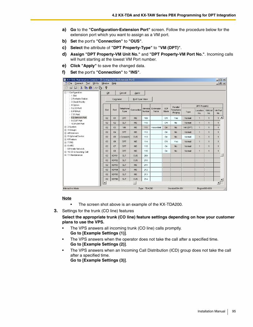
4.2 KX-TDA and KX-TAW Series PBX Programming for DPT Integration
a) Go to the "Configuration-Extension Port" screen. Follow the procedure below for the extension port which you want to assign as a VM port.
b) Set the port's "Connection" to "OUS".
c) Select the attribute of "DPT Property-Type" to "VM (DPT)".
d) Assign "DPT Property-VM Unit No." and "DPT Property-VM Port No.". Incoming calls will hunt starting at the lowest VM Port number.
e) Click "Apply" to save the changed data.
f) Set the port's "Connection" to "INS".
Note
• The screen shot above is an example of the KX-TDA200.
3. Settings for the trunk (CO line) features
Select the appropriate trunk (CO line) feature settings depending on how your customer plans to use the VPS.
• The VPS answers all incoming trunk (CO line) calls promptly. Go to [Example Settings (1)].
• The VPS answers when the operator does not take the call after a specified time. Go to [Example Settings (2)].
• The VPS answers when an Incoming Call Distribution (ICD) group does not take the call after a specified time. Go to [Example Settings (3)].
Installation Manual 95
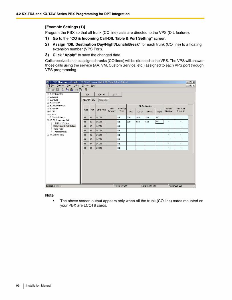
4.2 KX-TDA and KX-TAW Series PBX Programming for DPT Integration
[Example Settings (1)]
Program the PBX so that all trunk (CO line) calls are directed to the VPS (DIL feature).
1) Go to the "CO & Incoming Call-DIL Table & Port Setting" screen.
2) Assign "DIL Destination Day/Night/Lunch/Break" for each trunk (CO line) to a floating extension number (VPS Port).
3) Click "Apply" to save the changed data.
Calls received on the assigned trunks (CO lines) will be directed to the VPS. The VPS will answer those calls using the service (AA, VM, Custom Service, etc.) assigned to each VPS port through VPS programming.
Note
• The above screen output appears only when all the trunk (CO line) cards mounted on your PBX are LCOT8 cards.
96 Installation Manual
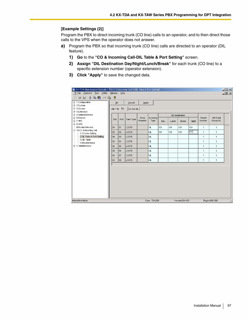
4.2 KX-TDA and KX-TAW Series PBX Programming for DPT Integration
[Example Settings (2)]
Program the PBX to direct incoming trunk (CO line) calls to an operator, and to then direct those calls to the VPS when the operator does not answer.
a) Program the PBX so that incoming trunk (CO line) calls are directed to an operator (DIL feature).
1) Go to the "CO & Incoming Call-DIL Table & Port Setting" screen.
2) Assign "DIL Destination Day/Night/Lunch/Break" for each trunk (CO line) to a specific extension number (operator extension).
3) Click "Apply" to save the changed data.
Installation Manual 97
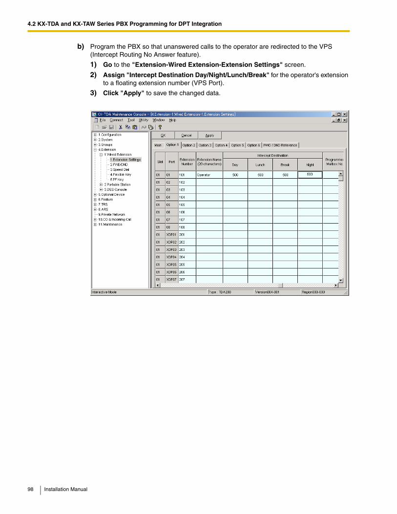
4.2 KX-TDA and KX-TAW Series PBX Programming for DPT Integration
b) Program the PBX so that unanswered calls to the operator are redirected to the VPS (Intercept Routing No Answer feature).
1) Go to the "Extension-Wired Extension-Extension Settings" screen.
2) Assign "Intercept Destination Day/Night/Lunch/Break" for the operator's extension to a floating extension number (VPS Port).
3) Click "Apply" to save the changed data.
98 Installation Manual
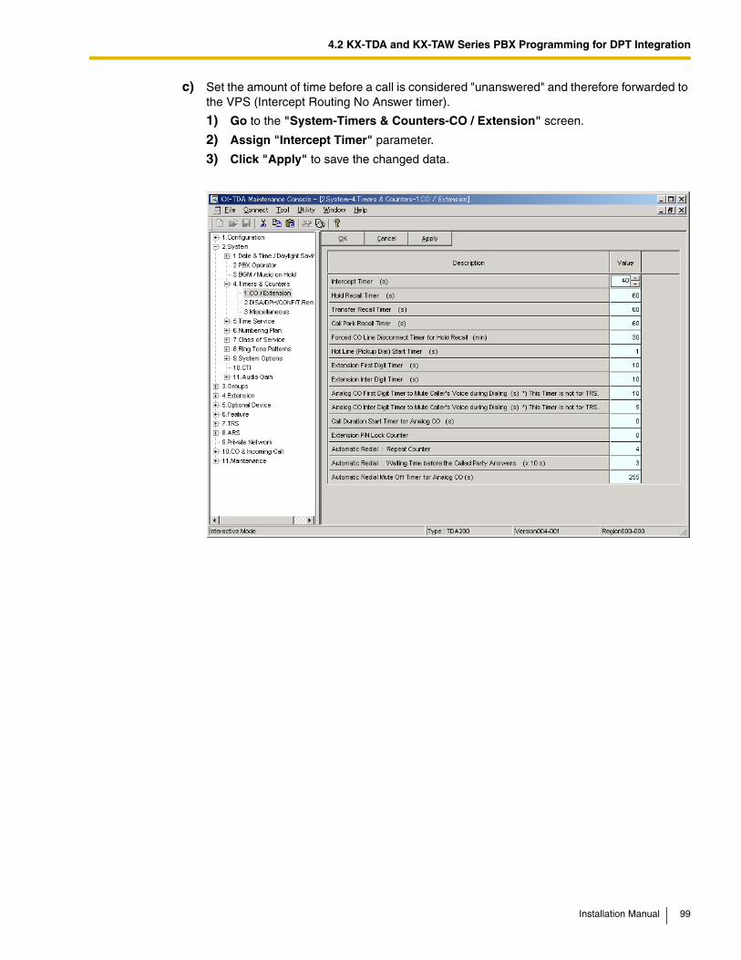
4.2 KX-TDA and KX-TAW Series PBX Programming for DPT Integration
c) Set the amount of time before a call is considered "unanswered" and therefore forwarded to the VPS (Intercept Routing No Answer timer).
1) Go to the "System-Timers & Counters-CO / Extension" screen.
2) Assign "Intercept Timer" parameter.
3) Click "Apply" to save the changed data.
Installation Manual 99
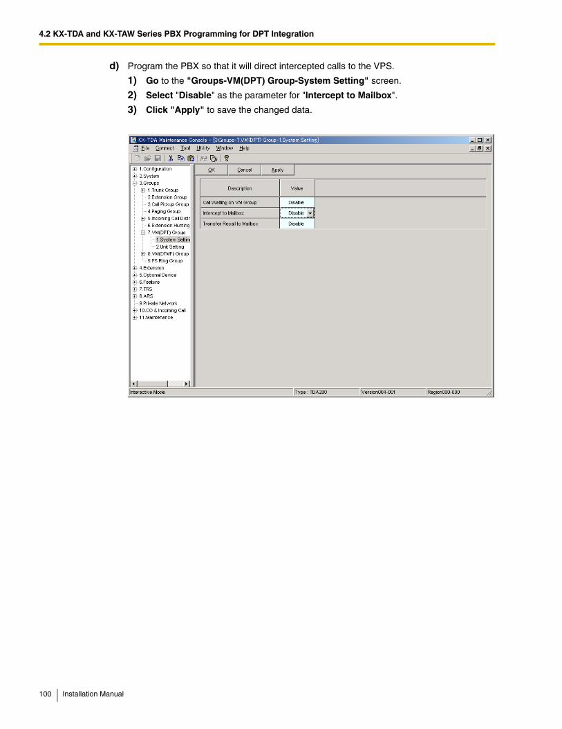
4.2 KX-TDA and KX-TAW Series PBX Programming for DPT Integration
d) Program the PBX so that it will direct intercepted calls to the VPS.
1) Go to the "Groups-VM(DPT) Group-System Setting" screen.
2) Select "Disable" as the parameter for "Intercept to Mailbox".
3) Click "Apply" to save the changed data.
100 Installation Manual
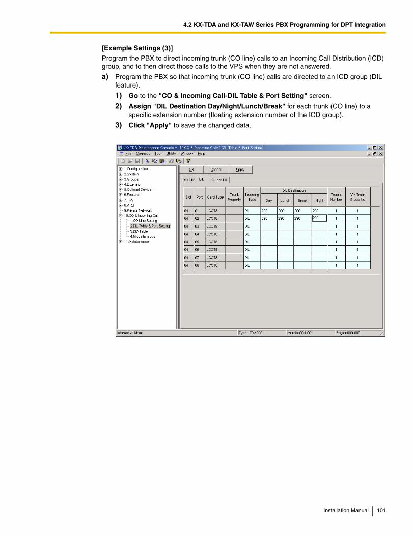
4.2 KX-TDA and KX-TAW Series PBX Programming for DPT Integration
[Example Settings (3)]
Program the PBX to direct incoming trunk (CO line) calls to an Incoming Call Distribution (ICD) group, and to then direct those calls to the VPS when they are not answered.
a) Program the PBX so that incoming trunk (CO line) calls are directed to an ICD group (DIL feature).
1) Go to the "CO & Incoming Call-DIL Table & Port Setting" screen.
2) Assign "DIL Destination Day/Night/Lunch/Break" for each trunk (CO line) to a specific extension number (floating extension number of the ICD group).
3) Click "Apply" to save the changed data.
Installation Manual 101
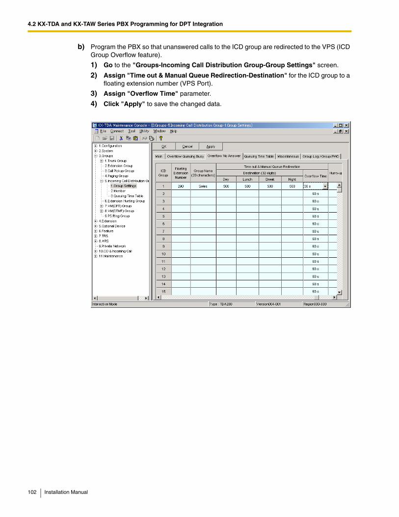
4.2 KX-TDA and KX-TAW Series PBX Programming for DPT Integration
b) Program the PBX so that unanswered calls to the ICD group are redirected to the VPS (ICD Group Overflow feature).
1) Go to the "Groups-Incoming Call Distribution Group-Group Settings" screen.
2) Assign "Time out & Manual Queue Redirection-Destination" for the ICD group to a floating extension number (VPS Port).
3) Assign "Overflow Time" parameter.
4) Click "Apply" to save the changed data.
102 Installation Manual
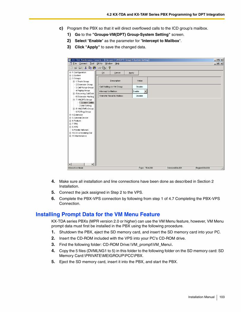
4.2 KX-TDA and KX-TAW Series PBX Programming for DPT Integration
c) Program the PBX so that it will direct overflowed calls to the ICD group's mailbox.
1) Go to the "Groups-VM(DPT) Group-System Setting" screen.
2) Select "Enable" as the parameter for "Intercept to Mailbox".
3) Click "Apply" to save the changed data.
4. Make sure all installation and line connections have been done as described in Section 2 Installation.
5. Connect the jack assigned in Step 2 to the VPS.
6. Complete the PBX-VPS connection by following from step 1 of 4.7 Completing the PBX-VPS Connection.
Installing Prompt Data for the VM Menu FeatureKX-TDA series PBXs (MPR version 2.0 or higher) can use the VM Menu feature, however, VM Menu prompt data must first be installed in the PBX using the following procedure.
1. Shutdown the PBX, eject the SD memory card, and insert the SD memory card into your PC.
2. Insert the CD-ROM included with the VPS into your PC's CD-ROM drive.
3. Find the following folder: CD-ROM Drive:\VM_prompt\VM_Menu\.
4. Copy the 5 files (DVMLNG1 to 5) in this folder to the following folder on the SD memory card: SD Memory Card:\PRIVATE\MEIGROUP\PCC\PBX.
5. Eject the SD memory card, insert it into the PBX, and start the PBX.
Installation Manual 103
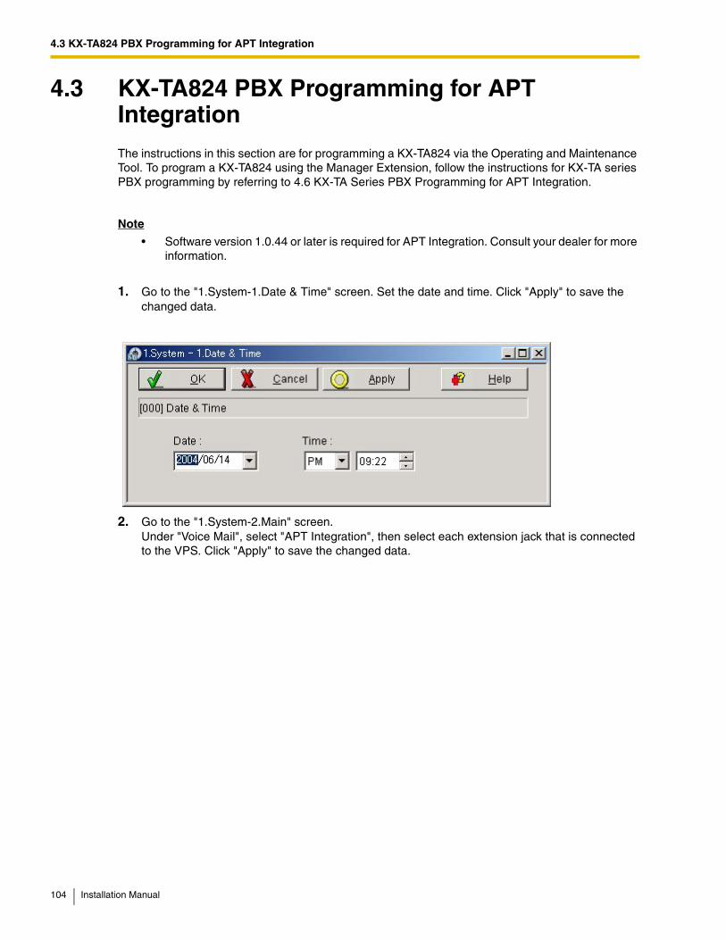
4.3 KX-TA824 PBX Programming for APT Integration
4.3 KX-TA824 PBX Programming for APT IntegrationThe instructions in this section are for programming a KX-TA824 via the Operating and Maintenance Tool. To program a KX-TA824 using the Manager Extension, follow the instructions for KX-TA series PBX programming by referring to 4.6 KX-TA Series PBX Programming for APT Integration.
Note
• Software version 1.0.44 or later is required for APT Integration. Consult your dealer for more information.
1. Go to the "1.System-1.Date & Time" screen. Set the date and time. Click "Apply" to save the changed data.
2. Go to the "1.System-2.Main" screen. Under "Voice Mail", select "APT Integration", then select each extension jack that is connected to the VPS. Click "Apply" to save the changed data.
104 Installation Manual
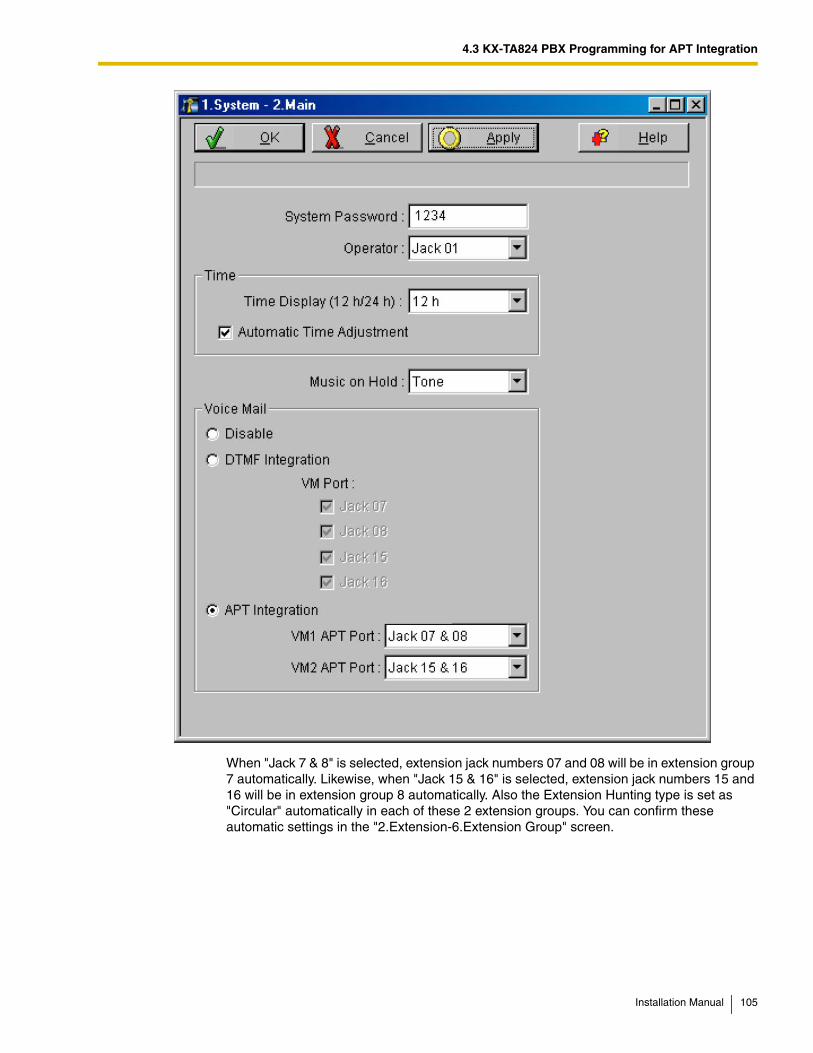
4.3 KX-TA824 PBX Programming for APT Integration
When "Jack 7 & 8" is selected, extension jack numbers 07 and 08 will be in extension group 7 automatically. Likewise, when "Jack 15 & 16" is selected, extension jack numbers 15 and 16 will be in extension group 8 automatically. Also the Extension Hunting type is set as "Circular" automatically in each of these 2 extension groups. You can confirm these automatic settings in the "2.Extension-6.Extension Group" screen.
Installation Manual 105
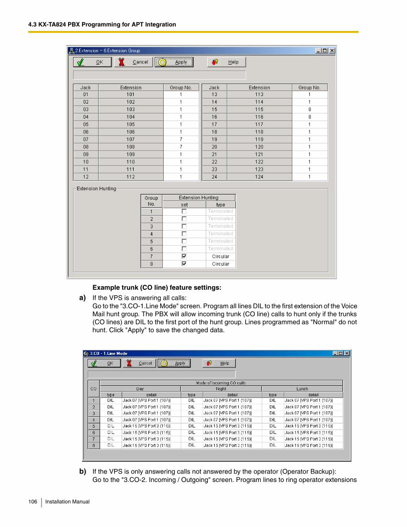
4.3 KX-TA824 PBX Programming for APT Integration
Example trunk (CO line) feature settings:
a) If the VPS is answering all calls: Go to the "3.CO-1.Line Mode" screen. Program all lines DIL to the first extension of the Voice Mail hunt group. The PBX will allow incoming trunk (CO line) calls to hunt only if the trunks (CO lines) are DIL to the first port of the hunt group. Lines programmed as "Normal" do not hunt. Click "Apply" to save the changed data.
b) If the VPS is only answering calls not answered by the operator (Operator Backup): Go to the "3.CO-2. Incoming / Outgoing" screen. Program lines to ring operator extensions
106 Installation Manual
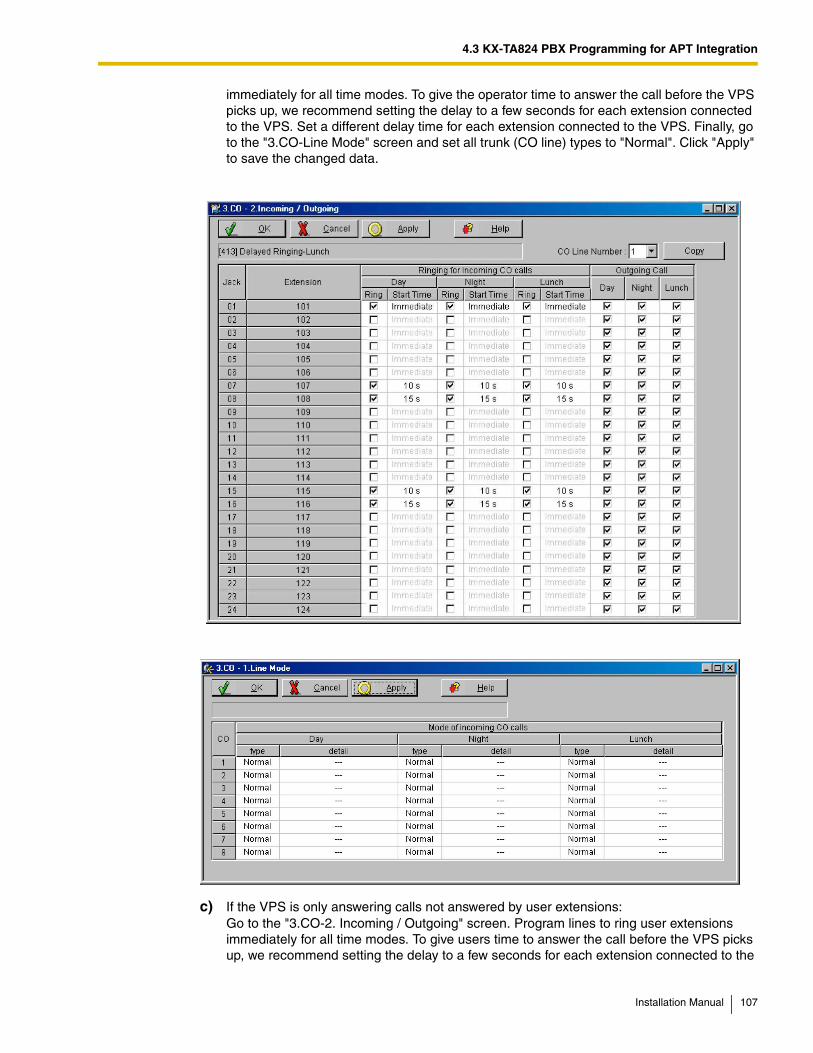
4.3 KX-TA824 PBX Programming for APT Integration
immediately for all time modes. To give the operator time to answer the call before the VPS picks up, we recommend setting the delay to a few seconds for each extension connected to the VPS. Set a different delay time for each extension connected to the VPS. Finally, go to the "3.CO-Line Mode" screen and set all trunk (CO line) types to "Normal". Click "Apply" to save the changed data.
c) If the VPS is only answering calls not answered by user extensions: Go to the "3.CO-2. Incoming / Outgoing" screen. Program lines to ring user extensions immediately for all time modes. To give users time to answer the call before the VPS picks up, we recommend setting the delay to a few seconds for each extension connected to the
Installation Manual 107
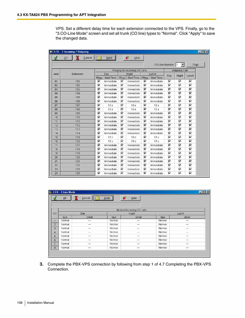
4.3 KX-TA824 PBX Programming for APT Integration
VPS. Set a different delay time for each extension connected to the VPS. Finally, go to the "3.CO-Line Mode" screen and set all trunk (CO line) types to "Normal". Click "Apply" to save the changed data.
3. Complete the PBX-VPS connection by following from step 1 of 4.7 Completing the PBX-VPS Connection.
108 Installation Manual
4.4 KX-TD Series PBX Programming for DPT Integration
4.4 KX-TD Series PBX Programming for DPT IntegrationFor KX-TD500 programming, refer to 4.5 KX-TD500 PBX Programming for DPT Integration.
Programming procedures and availability may vary by PBX model, software version, etc. Refer to the documentation included with the PBX or consult your dealer for more information.
Note
• Do not use system programs [106] or [602] for DPT Integration.
• The next 2 sections (4.4.1 KX-TD Series PBX Programming via the Manager's Extension and 4.4.2 KX-TD1232 Series PBX Programming via the Operating and Maintenance Tool) use the KX-TD1232 as an example. Refer to these examples when configuring the KX-TA1232 and KX-TD816.
4.4.1 KX-TD Series PBX Programming via the Manager's Extension
For KX-TD500 programming, refer to 4.5 KX-TD500 PBX Programming for DPT Integration.
It is important that the PBX has the proper software level to allow DPT Integration with the VPS. Follow the procedures below to confirm the software level, then complete the required programming before starting up the VPS.
Note
• There are 2 methods of programming available for the KX-TD1232. The instructions below show how to program without the operating and maintenance tool. For instructions on programming with the operating and maintenance tool, please see 4.4.2 KX-TD1232 Series PBX Programming via the Operating and Maintenance Tool.
All of the following procedures must be performed through system programming. Refer to the KX-TD1232 Programming Guide or Installation Manual for instructions on how to enter the system programming mode.
Software Verification1. Verify Software—If you are configuring a 2-cabinet system, remember to check both cabinets.
The software must be the same in each. Check the software version of the KX-TD1232 using System Program [116].
Example: P231U60403XX
The underlined digits represent the software production date code (year, month, day). For DPT Integration, the production date must be 60403 or later.
If the software version of the PBX is lower than this, you may not be able to utilize some of the features available only with DPT Integration. For more information, consult your dealer.
From the SYS-PGM NO ? screen:
a) Enter [116].
b) Press the NEXT button (SP-PHONE).
Installation Manual 109
4.4 KX-TD Series PBX Programming for DPT Integration
c) Enter the system number ([0] or [1], master/slave). The PBX displays the ROM version and the date it was created.
2. Set the date and time using System Program [000].
3. Set PBX extension numbering using System Program [003].
4. Assign the Voice Mail port. This program tells the PBX which jack will be connected to the VPS. This allows the PBX to send the proper DPT Integration information to those ports.
Note
• You can assign a maximum of 6 jacks (12 ports) with the KX-TD816 and KX-TD1232.
• If you are configuring a 2-cabinet system, all Voice Mail Ports should be assigned to either the Master or Slave System.
From the SYS-PGM NO ? screen:
a) Enter [117].
b) Press the NEXT button (SP-PHONE).Screen output: M:
c) Enter the jack number (02-64) of the port you will use for the Voice Mail.
d) Press the STORE button.
e) Press END (HOLD) when finished.
5. Follow this step if you are setting flexible numbering. If you are not setting flexible numbering, continue from step 6.
Voice Mail Extension Number Assignment is automatically set. Use System Program [118] or [127] to assign an extension number to each Voice Mail port. Because each jack connected to the VPS provides 2 extensions, this enables you to assign extension numbers to each port. You can assign any extension number that is not already assigned to another port. To reach the VPS, users dial these extension numbers. It is not necessary to change the default programming for the extensions 165 and 166 (or 265 and 266).
From the SYS-PGM NO ? screen:
a) Enter [118].
b) Press the NEXT button (SP-PHONE).
Screen output: VM NO?
c) Press the NEXT button (SP-PHONE).Screen output: VM-01:#_ _ -1: 165 _ _ = the port number you entered in program 117
d) Enter the Extension Number that you want this port to have.The default extension number for port 1: 165; port 2: 166
e) Press the STORE button.
f) Repeat steps c, d, and e until all extension numbers are entered.
Conditions: Jack 01 cannot be used as a Voice Mail port. A jack programmed as a Manager Extension (System Program [006]) cannot be used in this program.
110 Installation Manual
4.4 KX-TD Series PBX Programming for DPT Integration
6. Make sure all installation and line connections have been completed as described in Section 2 Installation.
7. Connect the jack assigned in Step 4 to the VPS.
8. Complete the PBX-VPS connection by following from step 1 of 4.7 Completing the PBX-VPS Connection.
Conditions: No 2 jacks on the PBX can have the same extension number. If you try to enter a number that is already assigned, you will hear an error tone. Each digital extension connected provides 2 Voice Mail ports and must have 2 different extension numbers assigned.
Installation Manual 111
4.4 KX-TD Series PBX Programming for DPT Integration
4.4.2 KX-TD1232 Series PBX Programming via the Operating and Maintenance Tool
Follow these steps after communication between the KX-TD1232 and the programming software has been established. Refer to the Operating and Maintenance manual for connection information.
1. Check the software version.
a) Go to the Main Menu. Press the ALT key and the letter [V] at the same time.
b) Verify the Operating and Maintenance version being used.
Note
• If you have an older version of the maintenance tool but have the correct ROM version in the PBX, you may still program the KX-TD1232 but you must program using the Manager's Extension.
c) Verify the ROM version of the KX-TD1232.
Example: P231U60403XX
The underlined digits represent the software production date code (year, month, day). For DPT Integration, the production date must be 60403 or later.
If the software version of the PBX is lower than this, you may not be able to utilize some of the features available only with DPT Integration. For more information, consult your dealer.
Sample display: Connect DSHS: KX-TD1232 ROM Version: [---P231UxxxxxB] CAN DB data (PC): Empty Version: 4.03A5 [0008301332] MUK
112 Installation Manual
4.4 KX-TD Series PBX Programming for DPT Integration
2. Go to the Main Menu. Choose "System Data Programming" (BATCH [1] or INTERACTIVE [2]).
3. Choose "System" from the System Data Programming Main Menu.
4. Choose "Voice Mail Integration" from the System Menu.
5. First, enter the port numbers that will be connected to the VPS. If desired, change the default extension numbers of the Voice Mail ports.
6. Step 6 should only be completed if the VPS is going to answer all incoming trunk (CO line) calls directly.
Return to the System Data Programming Main Menu. Select "Line" and then select "CO Line Setting 1" or "CO Line Setting 2". Program all lines DIL to the first extension of the Voice Mail hunt group.
7. Continue from step 5 of 4.4.1 KX-TD Series PBX Programming via the Manager's Extension.
Installation Manual 113
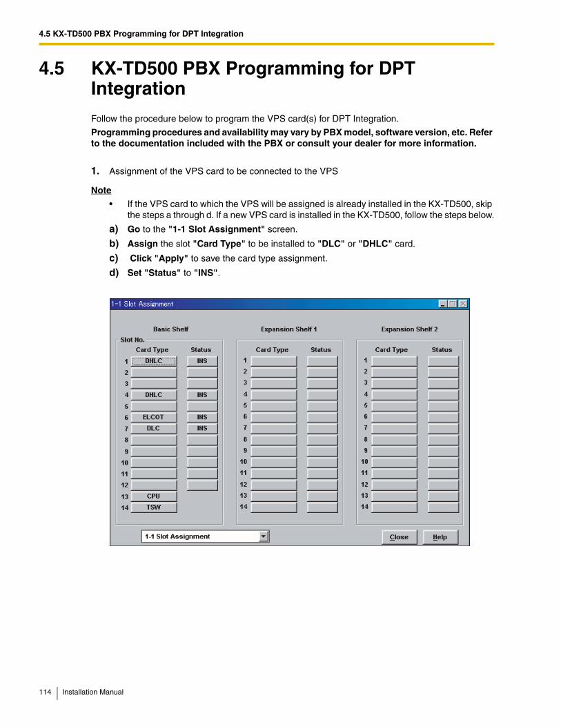
4.5 KX-TD500 PBX Programming for DPT Integration
4.5 KX-TD500 PBX Programming for DPT IntegrationFollow the procedure below to program the VPS card(s) for DPT Integration.
Programming procedures and availability may vary by PBX model, software version, etc. Refer to the documentation included with the PBX or consult your dealer for more information.
1. Assignment of the VPS card to be connected to the VPS
Note
• If the VPS card to which the VPS will be assigned is already installed in the KX-TD500, skip the steps a through d. If a new VPS card is installed in the KX-TD500, follow the steps below.
a) Go to the "1-1 Slot Assignment" screen.
b) Assign the slot "Card Type" to be installed to "DLC" or "DHLC" card.
c) Click "Apply" to save the card type assignment.
d) Set "Status" to "INS".
114 Installation Manual
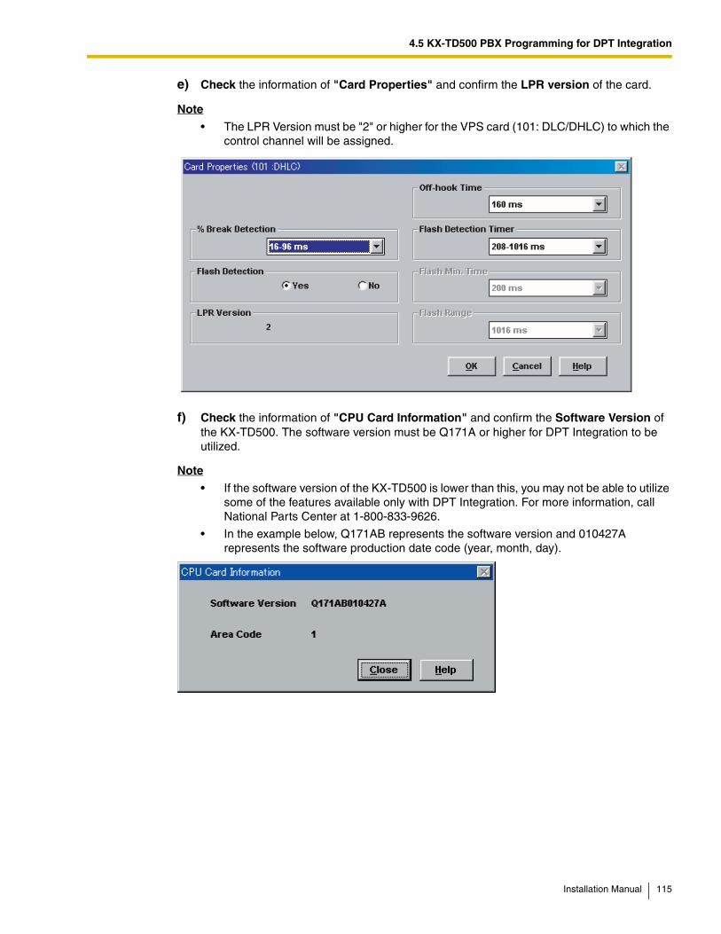
4.5 KX-TD500 PBX Programming for DPT Integration
e) Check the information of "Card Properties" and confirm the LPR version of the card.
Note
• The LPR Version must be "2" or higher for the VPS card (101: DLC/DHLC) to which the control channel will be assigned.
f) Check the information of "CPU Card Information" and confirm the Software Version of the KX-TD500. The software version must be Q171A or higher for DPT Integration to be utilized.
Note
• If the software version of the KX-TD500 is lower than this, you may not be able to utilize some of the features available only with DPT Integration. For more information, call National Parts Center at 1-800-833-9626.
• In the example below, Q171AB represents the software version and 010427A represents the software production date code (year, month, day).
Installation Manual 115
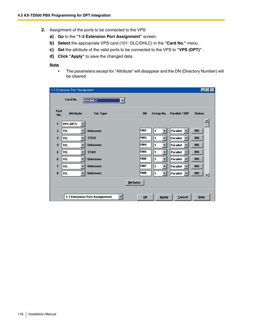
4.5 KX-TD500 PBX Programming for DPT Integration
2. Assignment of the ports to be connected to the VPS
a) Go to the "1-3 Extension Port Assignment" screen.
b) Select the appropriate VPS card (101: DLC/DHLC) in the "Card No." menu.
c) Set the attribute of the valid ports to be connected to the VPS to "VPS (DPT)" .
d) Click "Apply" to save the changed data.
Note
• The parameters except for "Attribute" will disappear and the DN (Directory Number) will be cleared.
116 Installation Manual
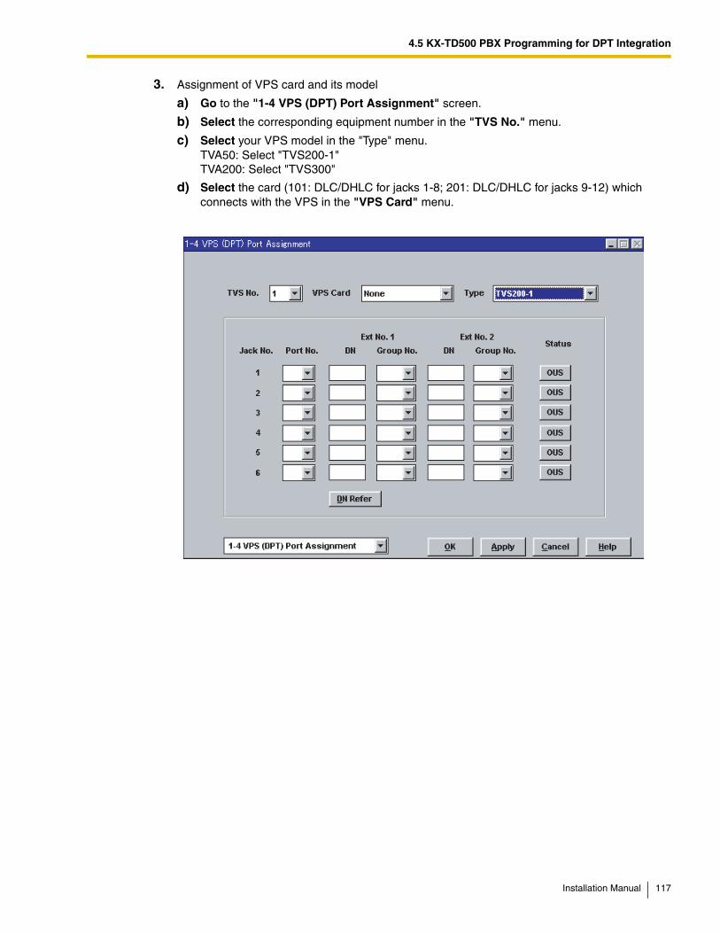
4.5 KX-TD500 PBX Programming for DPT Integration
3. Assignment of VPS card and its model
a) Go to the "1-4 VPS (DPT) Port Assignment" screen.
b) Select the corresponding equipment number in the "TVS No." menu.
c) Select your VPS model in the "Type" menu.TVA50: Select "TVS200-1"TVA200: Select "TVS300"
d) Select the card (101: DLC/DHLC for jacks 1-8; 201: DLC/DHLC for jacks 9-12) which connects with the VPS in the "VPS Card" menu.
Installation Manual 117
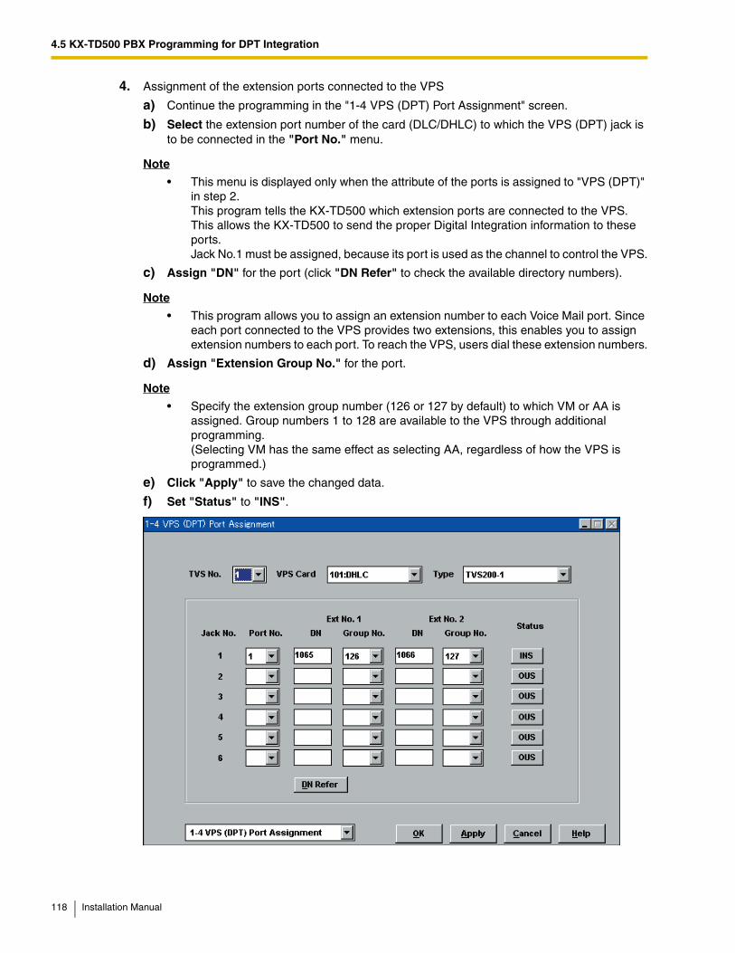
4.5 KX-TD500 PBX Programming for DPT Integration
4. Assignment of the extension ports connected to the VPS
a) Continue the programming in the "1-4 VPS (DPT) Port Assignment" screen.
b) Select the extension port number of the card (DLC/DHLC) to which the VPS (DPT) jack is to be connected in the "Port No." menu.
Note
• This menu is displayed only when the attribute of the ports is assigned to "VPS (DPT)" in step 2. This program tells the KX-TD500 which extension ports are connected to the VPS. This allows the KX-TD500 to send the proper Digital Integration information to these ports. Jack No.1 must be assigned, because its port is used as the channel to control the VPS.
c) Assign "DN" for the port (click "DN Refer" to check the available directory numbers).
Note
• This program allows you to assign an extension number to each Voice Mail port. Since each port connected to the VPS provides two extensions, this enables you to assign extension numbers to each port. To reach the VPS, users dial these extension numbers.
d) Assign "Extension Group No." for the port.
Note
• Specify the extension group number (126 or 127 by default) to which VM or AA is assigned. Group numbers 1 to 128 are available to the VPS through additional programming.(Selecting VM has the same effect as selecting AA, regardless of how the VPS is programmed.)
e) Click "Apply" to save the changed data.
f) Set "Status" to "INS".
118 Installation Manual
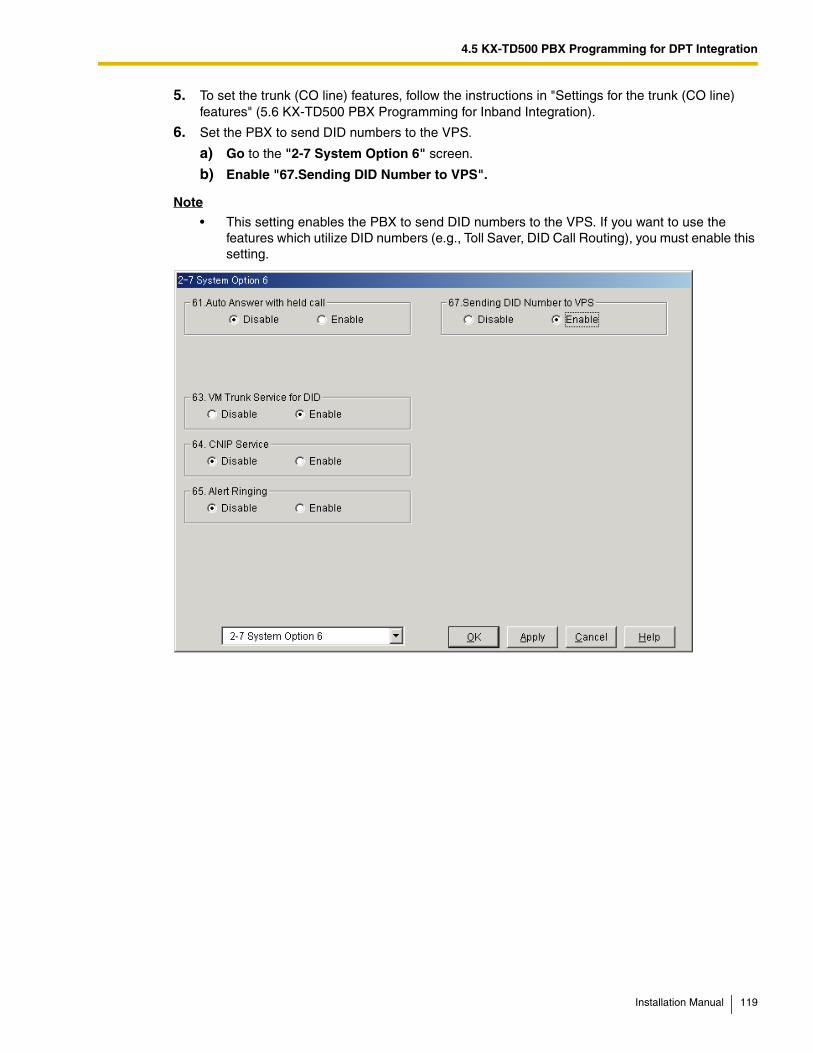
4.5 KX-TD500 PBX Programming for DPT Integration
5. To set the trunk (CO line) features, follow the instructions in "Settings for the trunk (CO line) features" (5.6 KX-TD500 PBX Programming for Inband Integration).
6. Set the PBX to send DID numbers to the VPS.
a) Go to the "2-7 System Option 6" screen.
b) Enable "67.Sending DID Number to VPS".
Note
• This setting enables the PBX to send DID numbers to the VPS. If you want to use the features which utilize DID numbers (e.g., Toll Saver, DID Call Routing), you must enable this setting.
Installation Manual 119

4.5 KX-TD500 PBX Programming for DPT Integration
7. Connect the jack assigned in Step 4 to the VPS.
8. Complete the PBX-VPS connection by following from step 1 of 4.7 Completing the PBX-VPS Connection.
120 Installation Manual
4.6 KX-TA Series PBX Programming for APT Integration
4.6 KX-TA Series PBX Programming for APT IntegrationFor KX-TA824 programming via the Operating and Maintenance Tool, refer to 4.3 KX-TA824 PBX Programming for APT Integration. For KX-TA1232 programming, refer to 4.4 KX-TD Series PBX Programming for DPT Integration.
Programming procedures and availability may vary by PBX model, software version, etc. Refer to the documentation included with the PBX or consult your dealer for more information.
Note
• The KX-TA824 can also be programmed via PC using the Operating and Maintenance Tool. Refer to 4.3 KX-TA824 PBX Programming for APT Integration.
• For KX-TA824, PBX software version 1.0.44 or later is required for APT Integration. Consult your dealer for more information.
It is important that the PBX has the proper software level to allow APT Integration with the VPS. Follow the procedures below to confirm the software level, then complete the required programming before starting up the VPS.
All of the following procedures must be completed after entering system programming. Refer to the KX-TA series Installation Manual for instructions on how to enter the system programming mode.
1. Using the Manager Extension, check the software version of the KX-TA series PBX using System Program [998].Example: Y581J000421(XX)The underlined digits represent the software production date code (year, month, day). For APT Integration, the production date must be 000421 or later.
If the software version of the PBX is lower than this, consult your dealer.
From the SYS-PGM NO ? screen:
a) Enter [998].
b) Press the NEXT button (SP-PHONE). The PBX displays the ROM version and the date it was created.
2. Set the date and time using System Program [000].Date and time are automatically synchronized between the VPS and the PBX during Quick Setup.
3. Set extension numbering using System Program [009].
4. Assign the voice mail port. This program tells the PBX which jacks will be connected to the VPS. This allows the PBX to send the proper APT Integration information to those ports. Jack 07, or jacks 07 and 08 can be assigned for the VPS1 as the voice mail port. Jack 15, or jacks 15 and 16 can be assigned for the VPS2.
Installation Manual 121
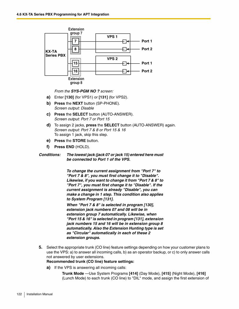
4.6 KX-TA Series PBX Programming for APT Integration
From the SYS-PGM NO ? screen:
a) Enter [130] (for VPS1) or [131] (for VPS2).
b) Press the NEXT button (SP-PHONE).Screen output: Disable
c) Press the SELECT button (AUTO-ANSWER).Screen output: Port 7 or Port 15
d) To assign 2 jacks, press the SELECT button (AUTO-ANSWER) again.Screen output: Port 7 & 8 or Port 15 & 16To assign 1 jack, skip this step.
e) Press the STORE button.
f) Press END (HOLD).
5. Select the appropriate trunk (CO line) feature settings depending on how your customer plans to use the VPS: a) to answer all incoming calls, b) as an operator backup, or c) to only answer calls not answered by user extensions.Recommended trunk (CO line) feature settings:
a) If the VPS is answering all incoming calls:
Trunk Mode —Use System Programs [414] (Day Mode), [415] (Night Mode), [416] (Lunch Mode) to each trunk (CO line) to "DIL" mode, and assign the first extension of
Conditions: The lowest jack (jack 07 or jack 15) entered here must be connected to Port 1 of the VPS.
To change the current assignment from "Port 7" to "Port 7 & 8", you must first change it to "Disable". Likewise, if you want to change it from "Port 7 & 8" to "Port 7", you must first change it to "Disable". If the current assignment is already "Disable", you can make a change in 1 step. This condition also applies to System Program [131].
When "Port 7 & 8" is selected in program [130], extension jack numbers 07 and 08 will be in extension group 7 automatically. Likewise, when "Port 15 & 16" is selected in program [131], extension jack numbers 15 and 16 will be in extension group 8 automatically. Also the Extension Hunting type is set as "Circular" automatically in each of these 2 extension groups.
Extensiongroup 8
KX-TA Series PBX
15
16
Port 1
Port 2
VPS 2
7
8
Port 1
Port 2
VPS 1
Extensiongroup 7
122 Installation Manual
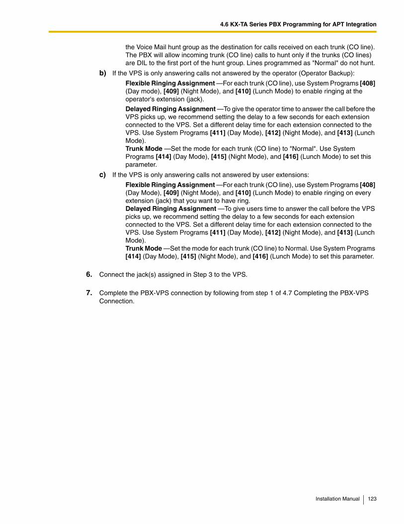
4.6 KX-TA Series PBX Programming for APT Integration
the Voice Mail hunt group as the destination for calls received on each trunk (CO line). The PBX will allow incoming trunk (CO line) calls to hunt only if the trunks (CO lines) are DIL to the first port of the hunt group. Lines programmed as "Normal" do not hunt.
b) If the VPS is only answering calls not answered by the operator (Operator Backup):
Flexible Ringing Assignment —For each trunk (CO line), use System Programs [408] (Day mode), [409] (Night Mode), and [410] (Lunch Mode) to enable ringing at the operator's extension (jack).
Delayed Ringing Assignment —To give the operator time to answer the call before the VPS picks up, we recommend setting the delay to a few seconds for each extension connected to the VPS. Set a different delay time for each extension connected to the VPS. Use System Programs [411] (Day Mode), [412] (Night Mode), and [413] (Lunch Mode).Trunk Mode —Set the mode for each trunk (CO line) to "Normal". Use System Programs [414] (Day Mode), [415] (Night Mode), and [416] (Lunch Mode) to set this parameter.
c) If the VPS is only answering calls not answered by user extensions:
Flexible Ringing Assignment —For each trunk (CO line), use System Programs [408] (Day Mode), [409] (Night Mode), and [410] (Lunch Mode) to enable ringing on every extension (jack) that you want to have ring.Delayed Ringing Assignment —To give users time to answer the call before the VPS picks up, we recommend setting the delay to a few seconds for each extension connected to the VPS. Set a different delay time for each extension connected to the VPS. Use System Programs [411] (Day Mode), [412] (Night Mode), and [413] (Lunch Mode).Trunk Mode —Set the mode for each trunk (CO line) to Normal. Use System Programs [414] (Day Mode), [415] (Night Mode), and [416] (Lunch Mode) to set this parameter.
6. Connect the jack(s) assigned in Step 3 to the VPS.
7. Complete the PBX-VPS connection by following from step 1 of 4.7 Completing the PBX-VPS Connection.
Installation Manual 123
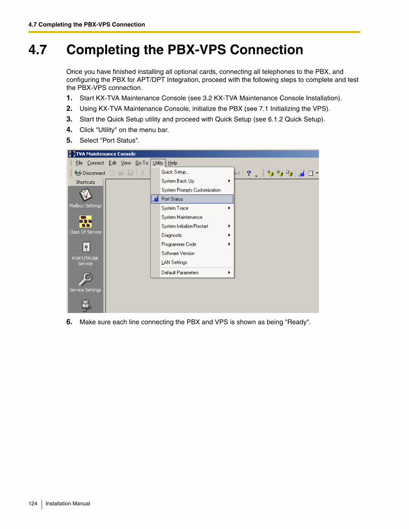
4.7 Completing the PBX-VPS Connection
4.7 Completing the PBX-VPS ConnectionOnce you have finished installing all optional cards, connecting all telephones to the PBX, and configuring the PBX for APT/DPT Integration, proceed with the following steps to complete and test the PBX-VPS connection.
1. Start KX-TVA Maintenance Console (see 3.2 KX-TVA Maintenance Console Installation).
2. Using KX-TVA Maintenance Console, initialize the PBX (see 7.1 Initializing the VPS).
3. Start the Quick Setup utility and proceed with Quick Setup (see 6.1.2 Quick Setup).
4. Click "Utility" on the menu bar.
5. Select "Port Status".
6. Make sure each line connecting the PBX and VPS is shown as being "Ready".
124 Installation Manual
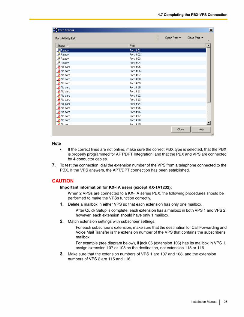
4.7 Completing the PBX-VPS Connection
Note
• If the correct lines are not online, make sure the correct PBX type is selected, that the PBX is properly programmed for APT/DPT Integration, and that the PBX and VPS are connected by 4-conductor cables.
7. To test the connection, dial the extension number of the VPS from a telephone connected to the PBX. If the VPS answers, the APT/DPT connection has been established.
CAUTIONImportant information for KX-TA users (except KX-TA1232):
When 2 VPSs are connected to a KX-TA series PBX, the following procedures should be performed to make the VPSs function correctly.
1. Delete a mailbox in either VPS so that each extension has only one mailbox.
After Quick Setup is complete, each extension has a mailbox in both VPS 1 and VPS 2, however, each extension should have only 1 mailbox.
2. Match extension settings with subscriber settings.
For each subscriber's extension, make sure that the destination for Call Forwarding and Voice Mail Transfer is the extension number of the VPS that contains the subscriber's mailbox.
For example (see diagram below), if jack 06 (extension 106) has its mailbox in VPS 1, assign extension 107 or 108 as the destination, not extension 115 or 116.
3. Make sure that the extension numbers of VPS 1 are 107 and 108, and the extension numbers of VPS 2 are 115 and 116.
Installation Manual 125
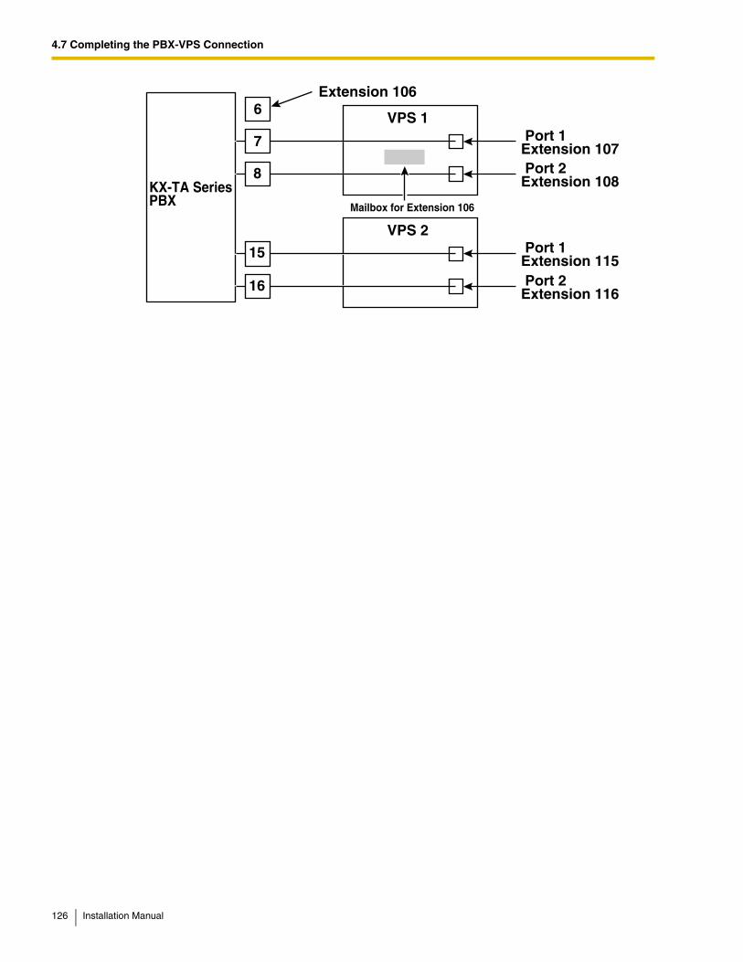
4.7 Completing the PBX-VPS Connection
7
6
8 KX-TA SeriesPBX
VPS 1 Port 1Extension 107 Port 2Extension 108
Extension 106
Mailbox for Extension 106
15
16
Port 1Extension 115 Port 2Extension 116
VPS 2
126 Installation Manual
Section 5
PBX Programming for Inband Integration (KX-TVA50 only)
This section explains how to configure selected Panasonic PBXs to use Inband Integration with the VPS.
Installation Manual 127
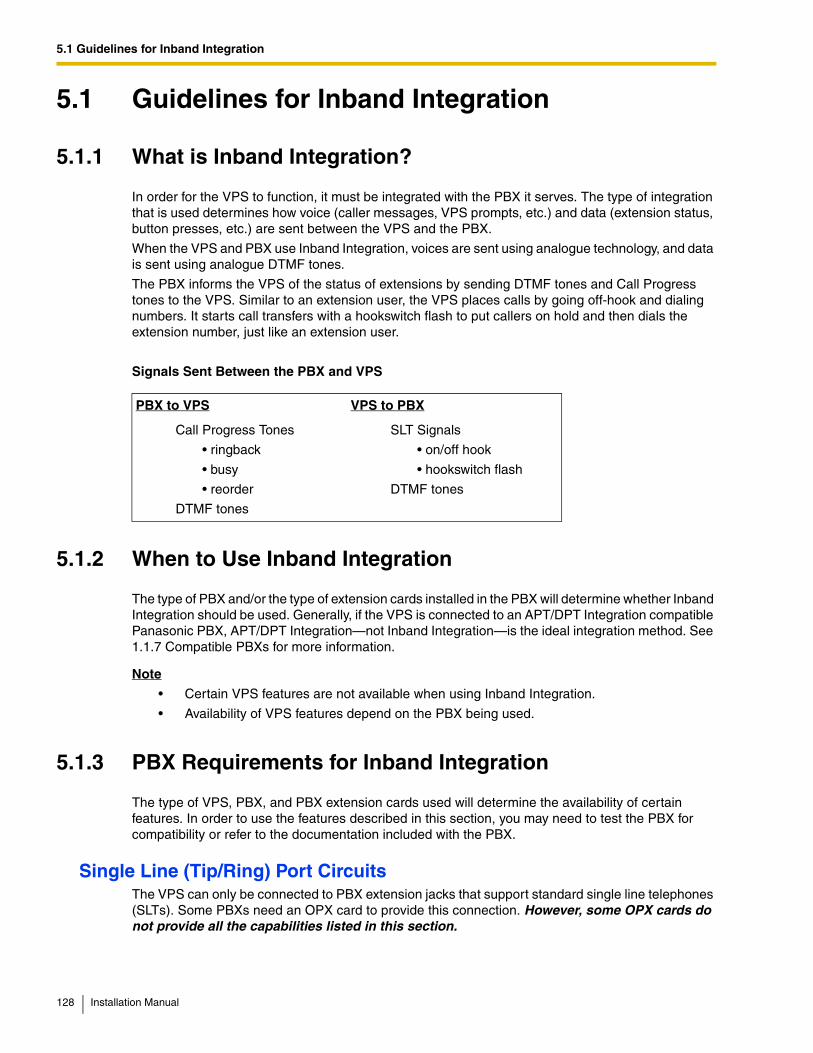
5.1 Guidelines for Inband Integration
5.1 Guidelines for Inband Integration
5.1.1 What is Inband Integration?
In order for the VPS to function, it must be integrated with the PBX it serves. The type of integration that is used determines how voice (caller messages, VPS prompts, etc.) and data (extension status, button presses, etc.) are sent between the VPS and the PBX.
When the VPS and PBX use Inband Integration, voices are sent using analogue technology, and data is sent using analogue DTMF tones.
The PBX informs the VPS of the status of extensions by sending DTMF tones and Call Progress tones to the VPS. Similar to an extension user, the VPS places calls by going off-hook and dialing numbers. It starts call transfers with a hookswitch flash to put callers on hold and then dials the extension number, just like an extension user.
Signals Sent Between the PBX and VPS
5.1.2 When to Use Inband Integration
The type of PBX and/or the type of extension cards installed in the PBX will determine whether Inband Integration should be used. Generally, if the VPS is connected to an APT/DPT Integration compatible Panasonic PBX, APT/DPT Integration—not Inband Integration—is the ideal integration method. See 1.1.7 Compatible PBXs for more information.
Note
• Certain VPS features are not available when using Inband Integration.
• Availability of VPS features depend on the PBX being used.
5.1.3 PBX Requirements for Inband Integration
The type of VPS, PBX, and PBX extension cards used will determine the availability of certain features. In order to use the features described in this section, you may need to test the PBX for compatibility or refer to the documentation included with the PBX.
Single Line (Tip/Ring) Port CircuitsThe VPS can only be connected to PBX extension jacks that support standard single line telephones (SLTs). Some PBXs need an OPX card to provide this connection. However, some OPX cards do not provide all the capabilities listed in this section.
PBX to VPS VPS to PBX
Call Progress Tones
• ringback
• busy
• reorder
DTMF tones
SLT Signals
• on/off hook
• hookswitch flash
DTMF tones
128 Installation Manual
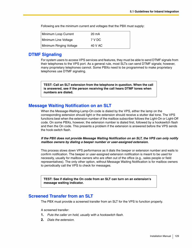
5.1 Guidelines for Inband Integration
Following are the minimum current and voltages that the PBX must supply:
DTMF SignalingFor system users to access VPS services and features, they must be able to send DTMF signals from their telephones to the VPS port. As a general rule, most SLTs can send DTMF signals; however, many proprietary telephones cannot. Some PBXs need to be programmed to make proprietary telephones use DTMF signaling.
Message Waiting Notification on an SLTWhen the Message-Waiting-Lamp-On code is dialed by the VPS, either the lamp on the corresponding extension should light or the extension should receive a stutter dial tone. The VPS functions best when the extension number of the mailbox subscriber follows the Light-On or Light-Off code. On some PBXs, however, the extension number is dialed first, followed by a hookswitch flash and then the On code. This presents a problem if the extension is answered before the VPS sends the hook-switch flash.
If the PBX does not provide Message Waiting Notification on an SLT, the VPS can only notify mailbox owners by dialing a beeper number or user-assigned extension.
This process slows down VPS performance as it dials the beeper or extension number and waits to confirm notification. The beeper or user-assigned extension notification is meant to be used for necessity, usually for mailbox owners who are often out of the office (e.g., sales people or field representatives). The only other option, without Message Waiting Notification is for mailbox owners to periodically call the VPS to check for messages.
Screened Transfer from an SLTThe PBX must provide a screened transfer from an SLT for the VPS to function properly.
A screened transfer:
1. Puts the caller on hold, usually with a hookswitch flash.
2. Dials the extension.
Minimum Loop Current 20 mA
Minimum Line Voltage 7 V DC
Minimum Ringing Voltage 40 V AC
TEST: Call an SLT extension from the telephone in question. When the call is answered, see if the person receiving the call hears DTMF tones when numbers are dialed.
TEST: See if dialing the On code from an SLT can turn on an extension's message waiting indicator.
Installation Manual 129
5.1 Guidelines for Inband Integration
3. Checks to see if the called subscriber is in, out, or on another line, and whether or not that subscriber accepts the transfer.
4. Completes the transfer (by going on-hook) or notifies the caller that the party is busy or not available. It then gives the caller an opportunity to leave a message.
If the PBX does not provide screened transfer from an SLT, the VPS cannot give callers the option to leave a message in a subscriber's mailbox.
Follow-on ID or Called Party IDWhen forwarding or transferring a call to the VPS, a PBX with Follow-on ID sends the mailbox number of the called subscriber to the VPS before connecting the caller. The VPS responds by playing that subscriber's personal greeting. This operation is sometimes called Call Forward to Mailbox. Without this feature, the VPS cannot immediately play the called extension's greeting message when the line is busy or there is no answer because the VPS does not know which mailbox to send the caller to.
TEST: Place a trunk (CO line) call from an SLT. See if you can set up a screened transfer to another extension. Next, try the same test with an intercom call. (The VPS may have to transfer both types of calls.)
130 Installation Manual
5.2 PBX Settings for Inband Integration
5.2 PBX Settings for Inband Integration
5.2.1 General Guidelines and Definitions
In order for the VPS and PBX to communicate properly, certain settings of both the VPS and PBX should be set to the same values.
Programming procedures and availability may vary by PBX model. Consult your dealer for more information.
5.2.2 Global Parameters
Global parameters are hardware settings that affect integration with the PBX. There is no need to change these settings in a typical installation. Only change these parameters when connecting the VPS to a PBX other than a KX-T series PBX. Each port on the VPS should match the type of signaling the PBX expects. If you need to change these settings for the VPS, refer to 2.6.1 Global Parameters in the Programming Manual, and refer also to the documentation included with the PBX.
• Flash/Recall Time The minimum length of time that the PBX requires to recognize a hookswitch flash/recall. Choose the amount that is equal to or greater than the PBX's setting.
• CPC Signal (Calling Party Control Signal) The length of time allowed for the short break in loop current that is used to indicate that the caller has hung up; usually set to NONE, since most PBXs do not provide this signal to single line ports. If choosing a setting other than NONE, use an amount equal to or less than the PBX or telephone company provided CPC signal.
• Disconnect Time The length of time that the line is temporarily unavailable after a call has ended.
• Delay After Dialing Before Analysis The length of time between the end of a call and the start of "Call Progress Tone" detection when an outgoing call is dialed.
• Maximum Time to Wait for Dial Tone The length of time that the VPS must wait for dial tone detection.
• Dial Start Mode Specifies whether to detect "Dial Tone" or wait the specified time in "Off-hook Delay" when an outgoing call is dialed.
• Off-hook Delay The length of delay time when "Off-hook Delay" is selected in "Dial Start Mode".
• Delay After Dialing Before On-hook The length of time that the VPS waits for an answer when an outgoing call is dialed. If the time period expires with no answer, the VPS disconnects the call.
• DTMF Cut Length The length of time for DTMF to be deleted when it is detected while in recording.
• Minimum Message Length Specifies the minimum message recording length. Messages shorter than the specified minimum recording length are discarded from the mailbox.
• Call Progress Tone Detection for Inband Mode Specifies whether to detect "Call Progress Tone".
Installation Manual 131
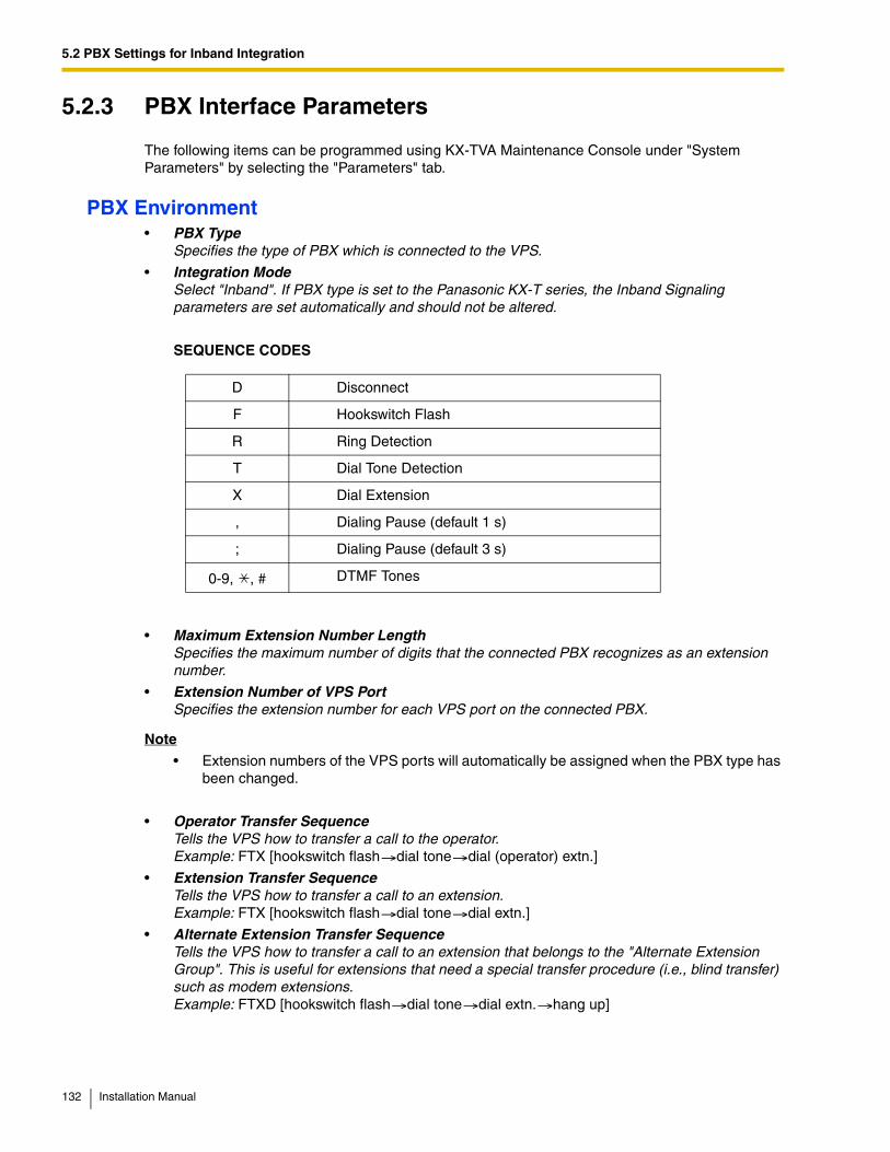
5.2 PBX Settings for Inband Integration
5.2.3 PBX Interface Parameters
The following items can be programmed using KX-TVA Maintenance Console under "System Parameters" by selecting the "Parameters" tab.
PBX Environment• PBX Type
Specifies the type of PBX which is connected to the VPS.
• Integration ModeSelect "Inband". If PBX type is set to the Panasonic KX-T series, the Inband Signaling parameters are set automatically and should not be altered.
SEQUENCE CODES
• Maximum Extension Number Length Specifies the maximum number of digits that the connected PBX recognizes as an extension number.
• Extension Number of VPS Port Specifies the extension number for each VPS port on the connected PBX.
Note
• Extension numbers of the VPS ports will automatically be assigned when the PBX type has been changed.
• Operator Transfer SequenceTells the VPS how to transfer a call to the operator.Example: FTX [hookswitch flash dial tone dial (operator) extn.]
• Extension Transfer SequenceTells the VPS how to transfer a call to an extension.Example: FTX [hookswitch flash dial tone dial extn.]
• Alternate Extension Transfer SequenceTells the VPS how to transfer a call to an extension that belongs to the "Alternate Extension Group". This is useful for extensions that need a special transfer procedure (i.e., blind transfer) such as modem extensions.Example: FTXD [hookswitch flash dial tone dial extn. hang up]
D Disconnect
F Hookswitch Flash
R Ring Detection
T Dial Tone Detection
X Dial Extension
, Dialing Pause (default 1 s)
; Dialing Pause (default 3 s)
0-9, , # DTMF Tones
132 Installation Manual
5.2 PBX Settings for Inband Integration
• Reconnect Sequence on BusyTells the VPS how to return to the caller if the called extension is busy. PBXs differ in how they handle this function. Test from an SLT to determine the sequence.
• Reconnect Sequence on No AnswerTells the VPS how to return to the caller if the called extension does not answer. PBXs differ in how they handle this function. Test from an SLT to determine the sequence.
• Reconnect Sequence on Refused CallTells the VPS how to return to the caller if the called extension's owner has enabled Call Screening to not take the call. PBXs differ in how they handle this function. Test from an SLT to determine the sequence.
• Light-On Sequence for Message Waiting LampThis is the dialing sequence that the VPS must use to turn on a message waiting lamp at an extension.
• Light-Off Sequence for Message Waiting LampThis is the dialing sequence that the VPS must use to turn off a message waiting lamp at an extension.
• Message Waiting Lamp Retry TimeSpecifies the number of times to retry the Message Waiting Lamp light-on/light-off process. This parameter is enabled only when the integration mode is Inband Integration or No Integration.
• Message Waiting Lamp Interval TimeSpecifies the time between retries for the Message Waiting Lamp light-on/light-off process. This parameter is enabled only when the integration mode is Inband Integration or No Integration.
• Call Waiting SequenceThis sequence is carried out by the VPS to perform call waiting when the called extension is busy. PBXs differ in how they handle this function. Test from an SLT to determine the sequence.
• Release Sequence for Call WaitingThis sequence is carried out by the VPS to release call waiting. PBXs differ in how they handle this function. Test from an SLT to determine the sequence.
Installation Manual 133
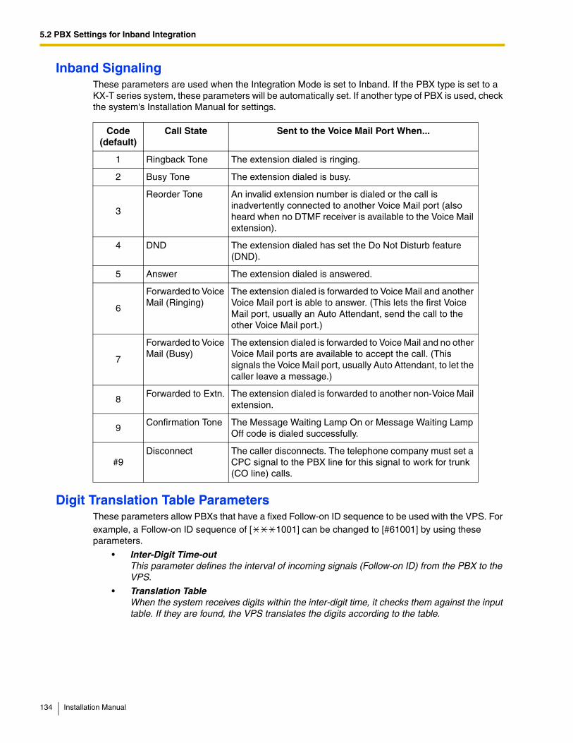
5.2 PBX Settings for Inband Integration
Inband SignalingThese parameters are used when the Integration Mode is set to Inband. If the PBX type is set to a KX-T series system, these parameters will be automatically set. If another type of PBX is used, check the system's Installation Manual for settings.
Digit Translation Table ParametersThese parameters allow PBXs that have a fixed Follow-on ID sequence to be used with the VPS. For example, a Follow-on ID sequence of [ 1001] can be changed to [#61001] by using these parameters.
• Inter-Digit Time-out This parameter defines the interval of incoming signals (Follow-on ID) from the PBX to the VPS.
• Translation Table When the system receives digits within the inter-digit time, it checks them against the input table. If they are found, the VPS translates the digits according to the table.
Code(default)
Call State Sent to the Voice Mail Port When...
1 Ringback Tone The extension dialed is ringing.
2 Busy Tone The extension dialed is busy.
3
Reorder Tone An invalid extension number is dialed or the call is inadvertently connected to another Voice Mail port (also heard when no DTMF receiver is available to the Voice Mail extension).
4 DND The extension dialed has set the Do Not Disturb feature (DND).
5 Answer The extension dialed is answered.
6
Forwarded to Voice Mail (Ringing)
The extension dialed is forwarded to Voice Mail and another Voice Mail port is able to answer. (This lets the first Voice Mail port, usually an Auto Attendant, send the call to the other Voice Mail port.)
7
Forwarded to Voice Mail (Busy)
The extension dialed is forwarded to Voice Mail and no other Voice Mail ports are available to accept the call. (This signals the Voice Mail port, usually Auto Attendant, to let the caller leave a message.)
8Forwarded to Extn. The extension dialed is forwarded to another non-Voice Mail
extension.
9Confirmation Tone The Message Waiting Lamp On or Message Waiting Lamp
Off code is dialed successfully.
#9Disconnect The caller disconnects. The telephone company must set a
CPC signal to the PBX line for this signal to work for trunk (CO line) calls.
134 Installation Manual
5.2 PBX Settings for Inband Integration
Transfer to Outside ParametersThese parameters specify how the VPS will transfer calls to trunks (CO lines) from the following services: Custom Service, Call Transfer Service, and Personal Custom Service.
[Outside Transfer Sequence]
• Call Transfer to Outside Sequence Specifies the sequence the VPS uses to transfer calls to trunks (CO lines).
• Call Transfer to Outside Reconnect Sequence on Busy Specifies the sequence the VPS uses to reconnect the line when the transferred party is busy.
• Call Transfer to Outside Reconnect Sequence on No Answer Specifies the sequence the VPS uses to reconnect the line when the transferred party does not answer.
• Outside Transfer Answer Mode Specifies the answering method the VPS uses to recognize whether the destination party has answered the transferred trunk (CO line) call.
Installation Manual 135
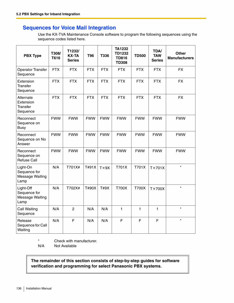
5.2 PBX Settings for Inband Integration
Sequences for Voice Mail IntegrationUse the KX-TVA Maintenance Console software to program the following sequences using the sequence codes listed here.
PBX TypeT308/T616
T1232/KX-TA Series
T96 T336
TA1232 TD1232 TD816 TD308
TD500TDA/TAW
Series
Other Manufacturers
Operator Transfer Sequence
FTX FTX FTX FTX FTX FTX FTX FX
Extension Transfer Sequence
FTX FTX FTX FTX FTX FTX FTX FX
Alternate Extension Transfer Sequence
FTX FTX FTX FTX FTX FTX FTX FX
Reconnect Sequence on Busy
FWW FWW FWW FWW FWW FWW FWW FWW
Reconnect Sequence on No Answer
FWW FWW FWW FWW FWW FWW FWW FWW
Reconnect Sequence on Refuse Call
FWW FWW FWW FWW FWW FWW FWW FWW
Light-On Sequence for Message Waiting Lamp
N/A T701X# T#91X T 9X T701X T701X T 701X *
Light-Off Sequence for Message Waiting Lamp
N/A T702X# T#90X T#9X T700X T700X T 700X *
Call Waiting Sequence
N/A 2 N/A N/A 1 1 1 *
Release Sequence for Call Waiting
N/A F N/A N/A F F F *
* Check with manufacturer.N/A Not Available
The remainder of this section consists of step-by-step guides for software verification and programming for select Panasonic PBX systems.
136 Installation Manual
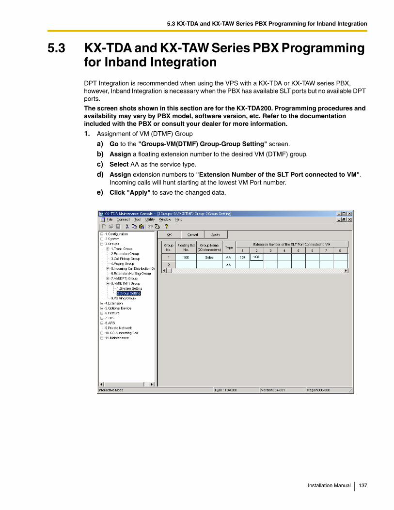
5.3 KX-TDA and KX-TAW Series PBX Programming for Inband Integration
5.3 KX-TDA and KX-TAW Series PBX Programming for Inband IntegrationDPT Integration is recommended when using the VPS with a KX-TDA or KX-TAW series PBX, however, Inband Integration is necessary when the PBX has available SLT ports but no available DPT ports.
The screen shots shown in this section are for the KX-TDA200. Programming procedures and availability may vary by PBX model, software version, etc. Refer to the documentation included with the PBX or consult your dealer for more information.
1. Assignment of VM (DTMF) Group
a) Go to the "Groups-VM(DTMF) Group-Group Setting" screen.
b) Assign a floating extension number to the desired VM (DTMF) group.
c) Select AA as the service type.
d) Assign extension numbers to "Extension Number of the SLT Port connected to VM". Incoming calls will hunt starting at the lowest VM Port number.
e) Click "Apply" to save the changed data.
Installation Manual 137
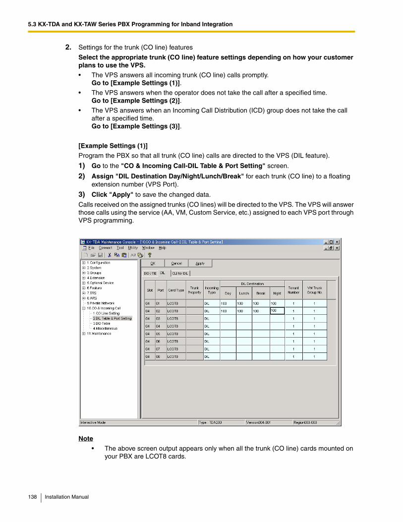
5.3 KX-TDA and KX-TAW Series PBX Programming for Inband Integration
2. Settings for the trunk (CO line) features
Select the appropriate trunk (CO line) feature settings depending on how your customer plans to use the VPS.
• The VPS answers all incoming trunk (CO line) calls promptly. Go to [Example Settings (1)].
• The VPS answers when the operator does not take the call after a specified time. Go to [Example Settings (2)].
• The VPS answers when an Incoming Call Distribution (ICD) group does not take the call after a specified time. Go to [Example Settings (3)].
[Example Settings (1)]
Program the PBX so that all trunk (CO line) calls are directed to the VPS (DIL feature).
1) Go to the "CO & Incoming Call-DIL Table & Port Setting" screen.
2) Assign "DIL Destination Day/Night/Lunch/Break" for each trunk (CO line) to a floating extension number (VPS Port).
3) Click "Apply" to save the changed data.
Calls received on the assigned trunks (CO lines) will be directed to the VPS. The VPS will answer those calls using the service (AA, VM, Custom Service, etc.) assigned to each VPS port through VPS programming.
Note
• The above screen output appears only when all the trunk (CO line) cards mounted on your PBX are LCOT8 cards.
138 Installation Manual
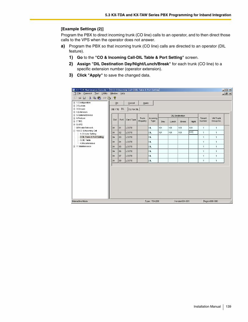
5.3 KX-TDA and KX-TAW Series PBX Programming for Inband Integration
[Example Settings (2)]
Program the PBX to direct incoming trunk (CO line) calls to an operator, and to then direct those calls to the VPS when the operator does not answer.
a) Program the PBX so that incoming trunk (CO line) calls are directed to an operator (DIL feature).
1) Go to the "CO & Incoming Call-DIL Table & Port Setting" screen.
2) Assign "DIL Destination Day/Night/Lunch/Break" for each trunk (CO line) to a specific extension number (operator extension).
3) Click "Apply" to save the changed data.
Installation Manual 139
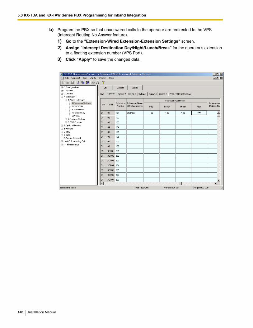
5.3 KX-TDA and KX-TAW Series PBX Programming for Inband Integration
b) Program the PBX so that unanswered calls to the operator are redirected to the VPS (Intercept Routing No Answer feature).
1) Go to the "Extension-Wired Extension-Extension Settings" screen.
2) Assign "Intercept Destination Day/Night/Lunch/Break" for the operator's extension to a floating extension number (VPS Port).
3) Click "Apply" to save the changed data.
140 Installation Manual

5.3 KX-TDA and KX-TAW Series PBX Programming for Inband Integration
c) Set the amount of time that passes before a call is considered "unanswered" and therefore forwarded to the VPS (Intercept Routing No Answer timer).
1) Go to the "System-Timers & Counters-CO / Extension" screen.
2) Assign the "Intercept Timer" parameter.
3) Click "Apply" to save the changed data.
Installation Manual 141
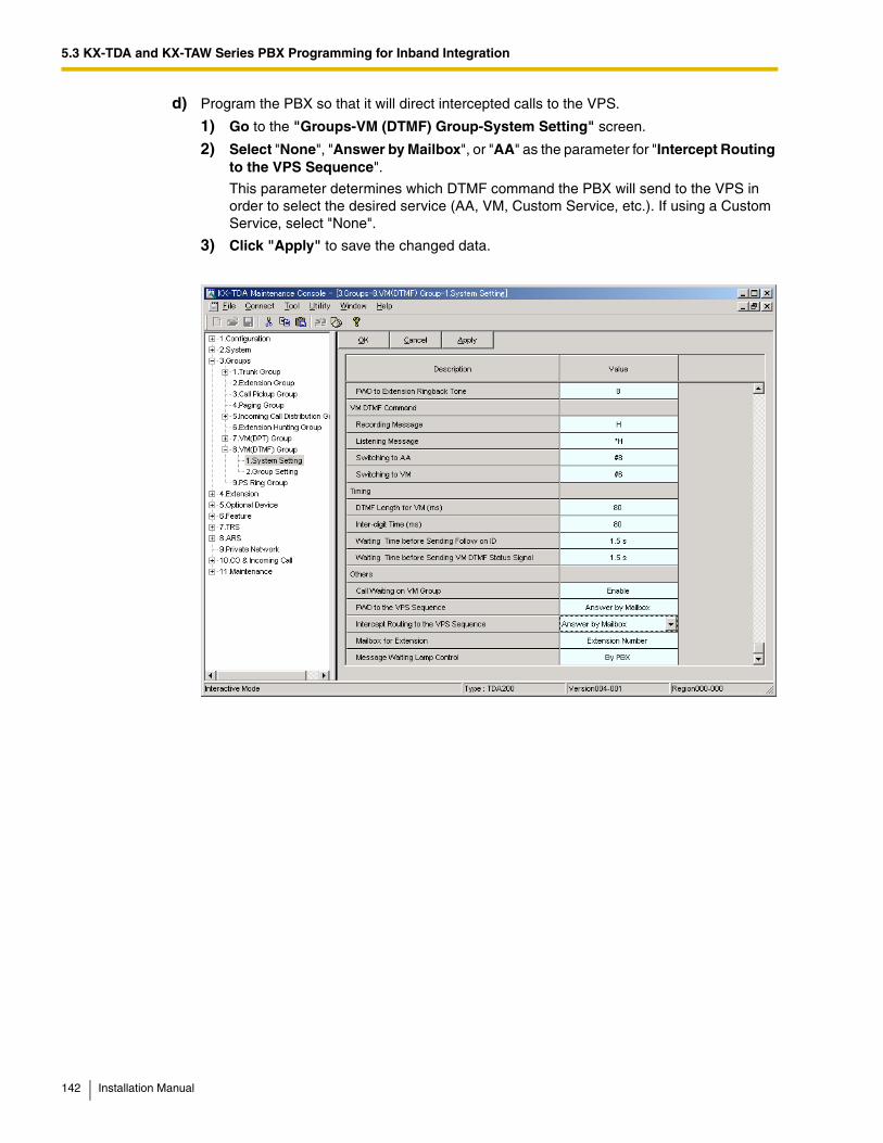
5.3 KX-TDA and KX-TAW Series PBX Programming for Inband Integration
d) Program the PBX so that it will direct intercepted calls to the VPS.
1) Go to the "Groups-VM (DTMF) Group-System Setting" screen.
2) Select "None", "Answer by Mailbox", or "AA" as the parameter for "Intercept Routing to the VPS Sequence".
This parameter determines which DTMF command the PBX will send to the VPS in order to select the desired service (AA, VM, Custom Service, etc.). If using a Custom Service, select "None".
3) Click "Apply" to save the changed data.
142 Installation Manual

5.3 KX-TDA and KX-TAW Series PBX Programming for Inband Integration
[Example Settings (3)]
Program the PBX to direct incoming trunk (CO line) calls to an Incoming Call Distribution (ICD) group, and to then direct those calls to the VPS when they are not answered.
a) Program the PBX so that incoming trunk (CO line) calls are directed to an ICD group (DIL feature).
1) Go to the "CO & Incoming Call-DIL Table & Port Setting" screen.
2) Assign "DIL Destination Day/Night/Lunch/Break" for each trunk (CO line) to a specific extension number (floating extension number of the ICD group).
3) Click "Apply" to save the changed data.
Installation Manual 143
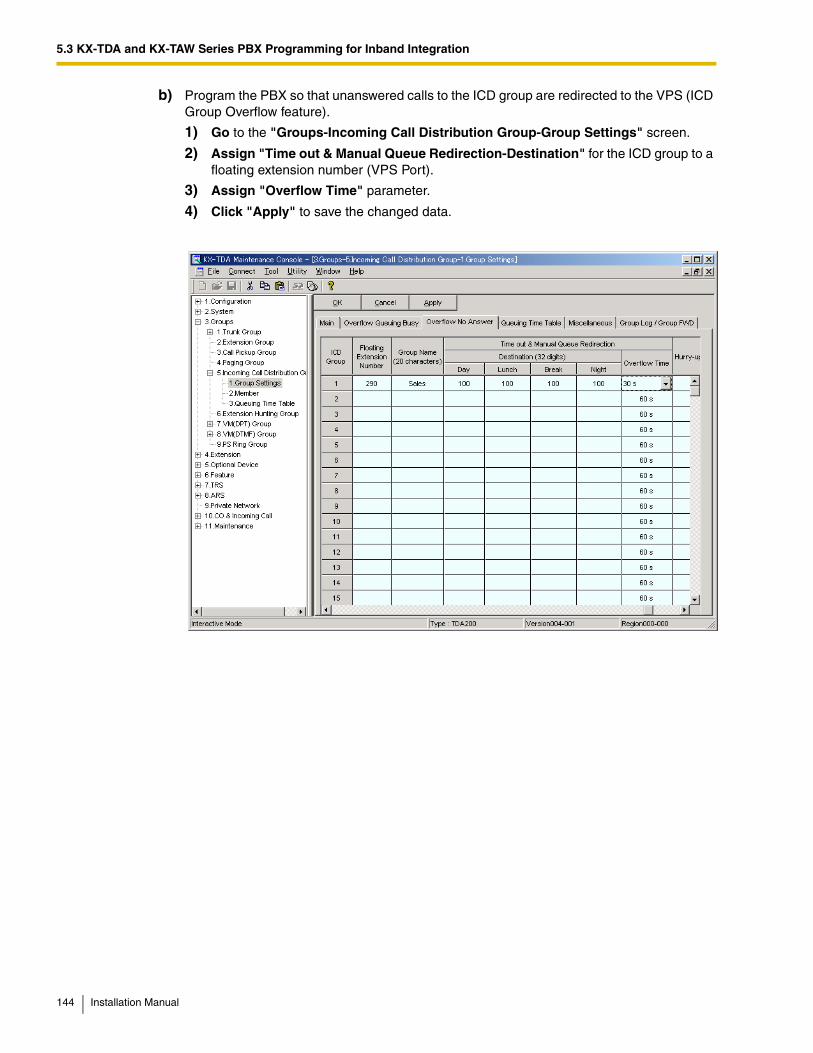
5.3 KX-TDA and KX-TAW Series PBX Programming for Inband Integration
b) Program the PBX so that unanswered calls to the ICD group are redirected to the VPS (ICD Group Overflow feature).
1) Go to the "Groups-Incoming Call Distribution Group-Group Settings" screen.
2) Assign "Time out & Manual Queue Redirection-Destination" for the ICD group to a floating extension number (VPS Port).
3) Assign "Overflow Time" parameter.
4) Click "Apply" to save the changed data.
144 Installation Manual
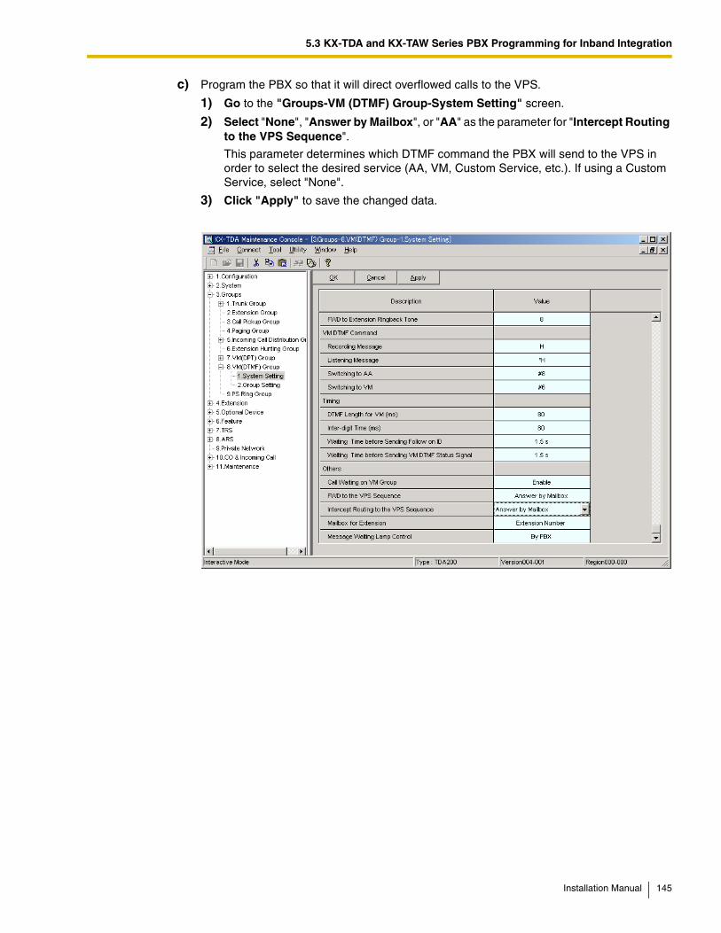
5.3 KX-TDA and KX-TAW Series PBX Programming for Inband Integration
c) Program the PBX so that it will direct overflowed calls to the VPS.
1) Go to the "Groups-VM (DTMF) Group-System Setting" screen.
2) Select "None", "Answer by Mailbox", or "AA" as the parameter for "Intercept Routing to the VPS Sequence".
This parameter determines which DTMF command the PBX will send to the VPS in order to select the desired service (AA, VM, Custom Service, etc.). If using a Custom Service, select "None".
3) Click "Apply" to save the changed data.
Installation Manual 145
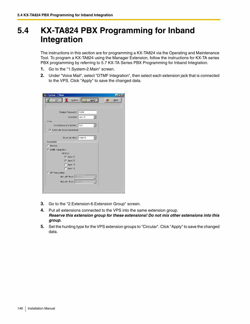
5.4 KX-TA824 PBX Programming for Inband Integration
5.4 KX-TA824 PBX Programming for Inband IntegrationThe instructions in this section are for programming a KX-TA824 via the Operating and Maintenance Tool. To program a KX-TA824 using the Manager Extension, follow the instructions for KX-TA series PBX programming by referring to 5.7 KX-TA Series PBX Programming for Inband Integration.
1. Go to the "1.System-2.Main" screen.
2. Under "Voice Mail", select "DTMF Integration", then select each extension jack that is connected to the VPS. Click "Apply" to save the changed data.
3. Go to the "2.Extension-6.Extension Group" screen.
4. Put all extensions connected to the VPS into the same extension group. Reserve this extension group for these extensions! Do not mix other extensions into this group.
5. Set the hunting type for the VPS extension groups to "Circular". Click "Apply" to save the changed data.
146 Installation Manual
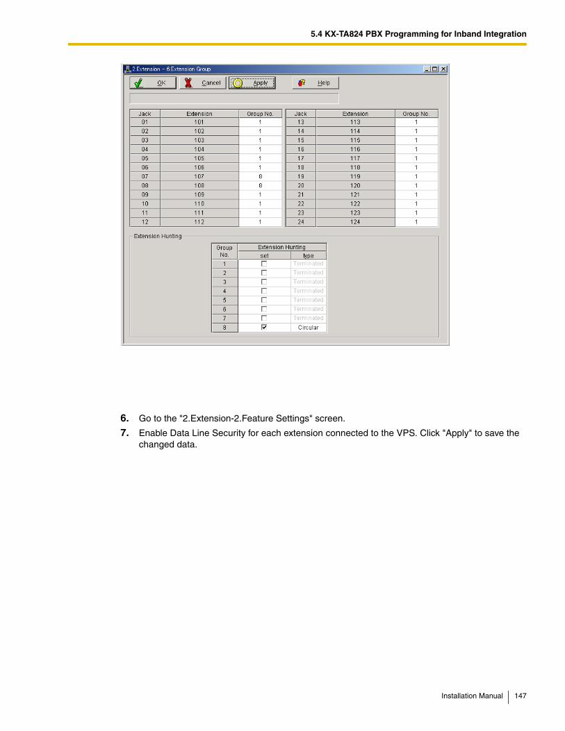
5.4 KX-TA824 PBX Programming for Inband Integration
6. Go to the "2.Extension-2.Feature Settings" screen.
7. Enable Data Line Security for each extension connected to the VPS. Click "Apply" to save the changed data.
Installation Manual 147
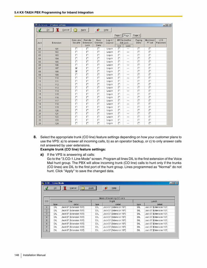
5.4 KX-TA824 PBX Programming for Inband Integration
8. Select the appropriate trunk (CO line) feature settings depending on how your customer plans to use the VPS: a) to answer all incoming calls, b) as an operator backup, or c) to only answer calls not answered by user extensions. Example trunk (CO line) feature settings:
a) If the VPS is answering all calls:Go to the "3.CO-1.Line Mode" screen. Program all lines DIL to the first extension of the Voice Mail hunt group. The PBX will allow incoming trunk (CO line) calls to hunt only if the trunks (CO lines) are DIL to the first port of the hunt group. Lines programmed as "Normal" do not hunt. Click "Apply" to save the changed data.
148 Installation Manual
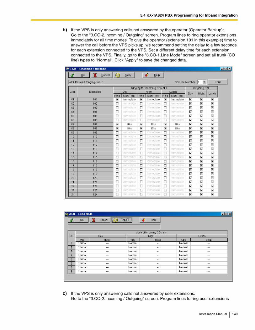
5.4 KX-TA824 PBX Programming for Inband Integration
b) If the VPS is only answering calls not answered by the operator (Operator Backup):Go to the "3.CO-2.Incoming / Outgoing" screen. Program lines to ring operator extensions immediately for all time modes. To give the operator (extension 101 in this example) time to answer the call before the VPS picks up, we recommend setting the delay to a few seconds for each extension connected to the VPS. Set a different delay time for each extension connected to the VPS. Finally, go to the "3.CO-1.Line Mode" screen and set all trunk (CO line) types to "Normal". Click "Apply" to save the changed data.
c) If the VPS is only answering calls not answered by user extensions:Go to the "3.CO-2.Incoming / Outgoing" screen. Program lines to ring user extensions
Installation Manual 149
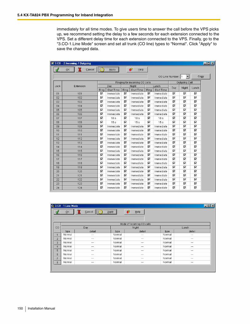
5.4 KX-TA824 PBX Programming for Inband Integration
immediately for all time modes. To give users time to answer the call before the VPS picks up, we recommend setting the delay to a few seconds for each extension connected to the VPS. Set a different delay time for each extension connected to the VPS. Finally, go to the "3.CO-1.Line Mode" screen and set all trunk (CO line) types to "Normal". Click "Apply" to save the changed data.
150 Installation Manual
5.5 KX-TD Series PBX Programming for Inband Integration
5.5 KX-TD Series PBX Programming for Inband IntegrationFor KX-TD500 programming, refer to 5.6 KX-TD500 PBX Programming for Inband Integration.
DPT Integration is recommended when using the VPS with the KX-TA1232, KX-TD816, or KX-TD1232, however, Inband Integration is necessary when the software version of the PBX does not support DPT Integration.
Programming procedures and availability may vary by PBX model, software version, etc. Refer to the documentation included with the PBX or consult your dealer for more information.
5.5.1 KX-TD Series PBX Programming via the Manager's Extension
For KX-TD500 programming, refer to 5.6 KX-TD500 PBX Programming for Inband Integration.
Select a maximum of 2 extension ports to be connected to the VPS. Plug each extension into a Voice Mail port.
Go to System Program [602] and assign the Voice Mail extensions to a different extension group. By default, all extensions are in Extension Group 1.
Go to System Program [106] and assign the new Extension Group to Auto Attendant (AA).
5.5.2 KX-TD Series PBX Programming via the Operating and Maintenance Tool
For KX-TD500 programming, refer to 5.6 KX-TD500 PBX Programming for Inband Integration.
1. Go to the Main Menu. Choose "System Data Programming". (BATCH [1] or INTERACTIVE [2]).
• Before choosing Batch Programming, you must open a file in the Disk File Management Menu (Item 3).
• Before choosing Interactive Programming, you must connect with the system in the DSHS Connect/Disconnect menu.
Installation Manual 151
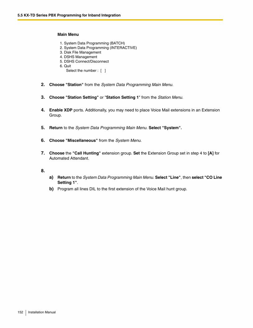
5.5 KX-TD Series PBX Programming for Inband Integration
Main Menu
2. Choose "Station" from the System Data Programming Main Menu.
3. Choose "Station Setting" or "Station Setting 1" from the Station Menu.
4. Enable XDP ports. Additionally, you may need to place Voice Mail extensions in an Extension Group.
5. Return to the System Data Programming Main Menu. Select "System".
6. Choose "Miscellaneous" from the System Menu.
7. Choose the "Call Hunting" extension group. Set the Extension Group set in step 4 to [A] for Automated Attendant.
8.a) Return to the System Data Programming Main Menu. Select "Line", then select "CO Line
Setting 1".
b) Program all lines DIL to the first extension of the Voice Mail hunt group.
1. System Data Programming (BATCH)2. System Data Programming (INTERACTIVE)3. Disk File Management4. DSHS Management5. DSHS Connect/Disconnect6. Quit Select the number : [ ]
152 Installation Manual
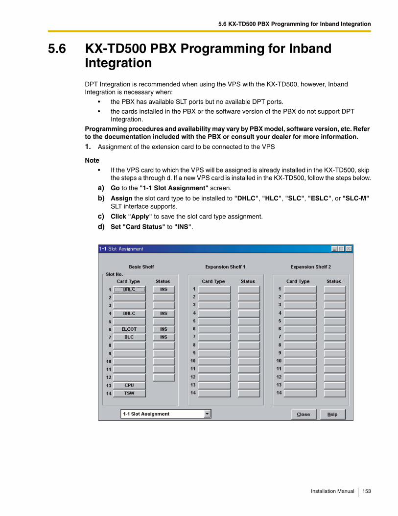
5.6 KX-TD500 PBX Programming for Inband Integration
5.6 KX-TD500 PBX Programming for Inband IntegrationDPT Integration is recommended when using the VPS with the KX-TD500, however, Inband Integration is necessary when:
• the PBX has available SLT ports but no available DPT ports.
• the cards installed in the PBX or the software version of the PBX do not support DPT Integration.
Programming procedures and availability may vary by PBX model, software version, etc. Refer to the documentation included with the PBX or consult your dealer for more information.
1. Assignment of the extension card to be connected to the VPS
Note
• If the VPS card to which the VPS will be assigned is already installed in the KX-TD500, skip the steps a through d. If a new VPS card is installed in the KX-TD500, follow the steps below.
a) Go to the "1-1 Slot Assignment" screen.
b) Assign the slot card type to be installed to "DHLC", "HLC", "SLC", "ESLC", or "SLC-M" SLT interface supports.
c) Click "Apply" to save the slot card type assignment.
d) Set "Card Status" to "INS".
Installation Manual 153
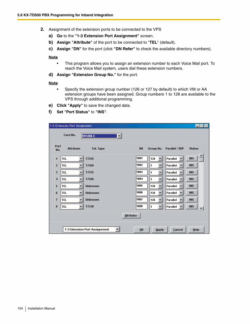
5.6 KX-TD500 PBX Programming for Inband Integration
2. Assignment of the extension ports to be connected to the VPS
a) Go to the "1-3 Extension Port Assignment" screen.
b) Assign "Attribute" of the port to be connected to "TEL" (default).
c) Assign "DN" for the port (click "DN Refer" to check the available directory numbers).
Note
• This program allows you to assign an extension number to each Voice Mail port. To reach the Voice Mail system, users dial these extension numbers.
d) Assign "Extension Group No." for the port.
Note
• Specify the extension group number (126 or 127 by default) to which VM or AA extension groups have been assigned. Group numbers 1 to 128 are available to the VPS through additional programming.
e) Click "Apply" to save the changed data.
f) Set "Port Status" to "INS".
154 Installation Manual
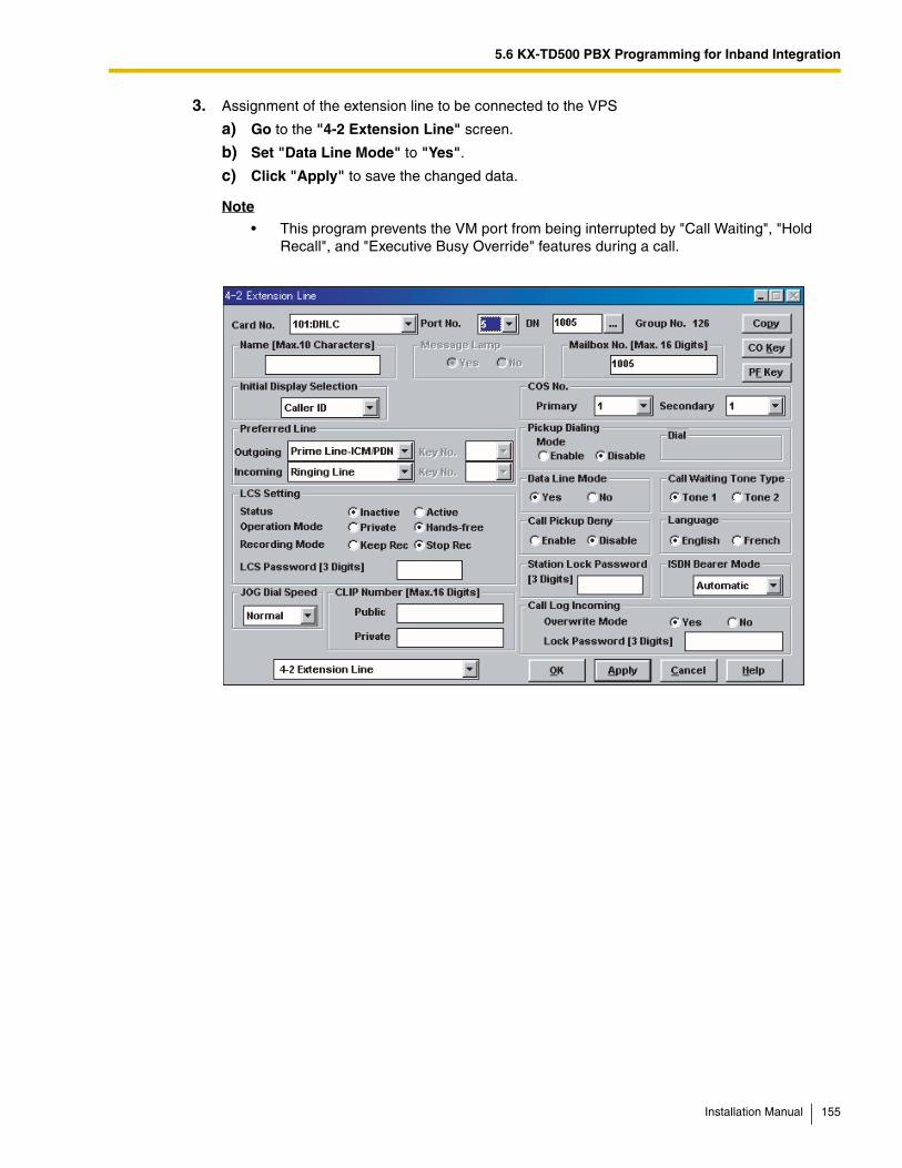
5.6 KX-TD500 PBX Programming for Inband Integration
3. Assignment of the extension line to be connected to the VPS
a) Go to the "4-2 Extension Line" screen.
b) Set "Data Line Mode" to "Yes".
c) Click "Apply" to save the changed data.
Note
• This program prevents the VM port from being interrupted by "Call Waiting", "Hold Recall", and "Executive Busy Override" features during a call.
Installation Manual 155
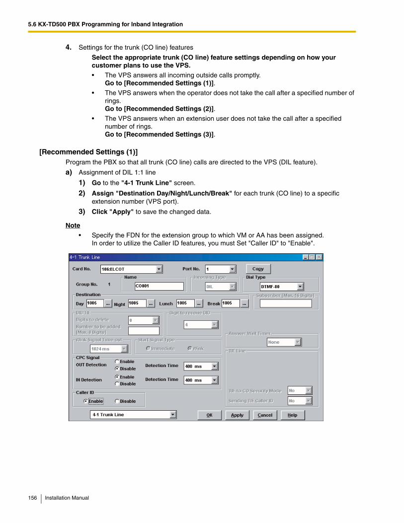
5.6 KX-TD500 PBX Programming for Inband Integration
4. Settings for the trunk (CO line) features
Select the appropriate trunk (CO line) feature settings depending on how your customer plans to use the VPS.
• The VPS answers all incoming outside calls promptly.Go to [Recommended Settings (1)].
• The VPS answers when the operator does not take the call after a specified number of rings.Go to [Recommended Settings (2)].
• The VPS answers when an extension user does not take the call after a specified number of rings.Go to [Recommended Settings (3)].
[Recommended Settings (1)]Program the PBX so that all trunk (CO line) calls are directed to the VPS (DIL feature).
a) Assignment of DIL 1:1 line
1) Go to the "4-1 Trunk Line" screen.
2) Assign "Destination Day/Night/Lunch/Break" for each trunk (CO line) to a specific extension number (VPS port).
3) Click "Apply" to save the changed data.
Note
• Specify the FDN for the extension group to which VM or AA has been assigned.In order to utilize the Caller ID features, you must Set "Caller ID" to "Enable".
156 Installation Manual
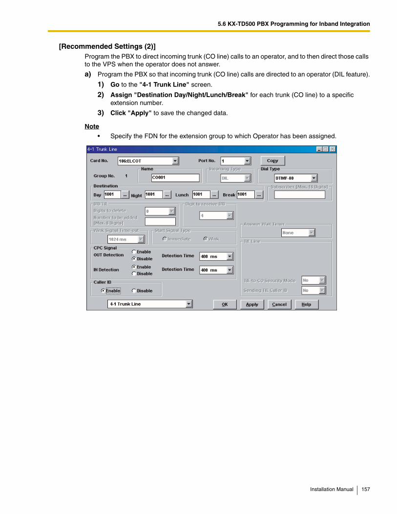
5.6 KX-TD500 PBX Programming for Inband Integration
[Recommended Settings (2)]Program the PBX to direct incoming trunk (CO line) calls to an operator, and to then direct those calls to the VPS when the operator does not answer.
a) Program the PBX so that incoming trunk (CO line) calls are directed to an operator (DIL feature).
1) Go to the "4-1 Trunk Line" screen.
2) Assign "Destination Day/Night/Lunch/Break" for each trunk (CO line) to a specific extension number.
3) Click "Apply" to save the changed data.
Note
• Specify the FDN for the extension group to which Operator has been assigned.
Installation Manual 157
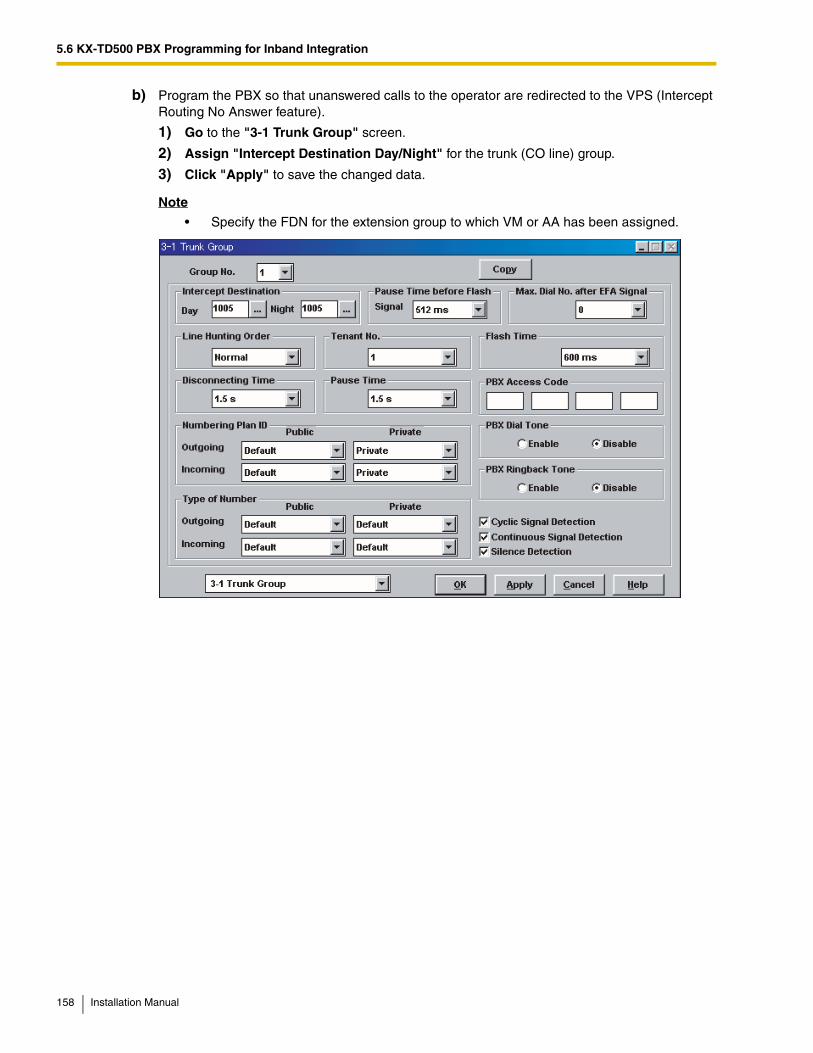
5.6 KX-TD500 PBX Programming for Inband Integration
b) Program the PBX so that unanswered calls to the operator are redirected to the VPS (Intercept Routing No Answer feature).
1) Go to the "3-1 Trunk Group" screen.
2) Assign "Intercept Destination Day/Night" for the trunk (CO line) group.
3) Click "Apply" to save the changed data.
Note
• Specify the FDN for the extension group to which VM or AA has been assigned.
158 Installation Manual
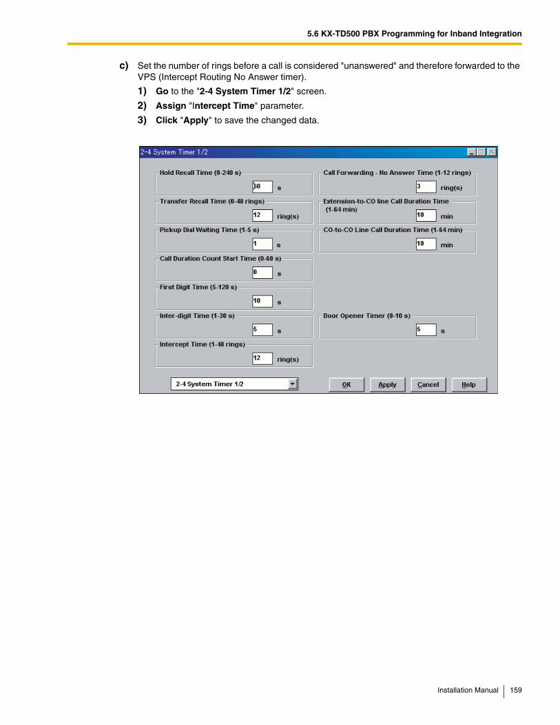
5.6 KX-TD500 PBX Programming for Inband Integration
c) Set the number of rings before a call is considered "unanswered" and therefore forwarded to the VPS (Intercept Routing No Answer timer).
1) Go to the "2-4 System Timer 1/2" screen.
2) Assign "Intercept Time" parameter.
3) Click "Apply" to save the changed data.
Installation Manual 159
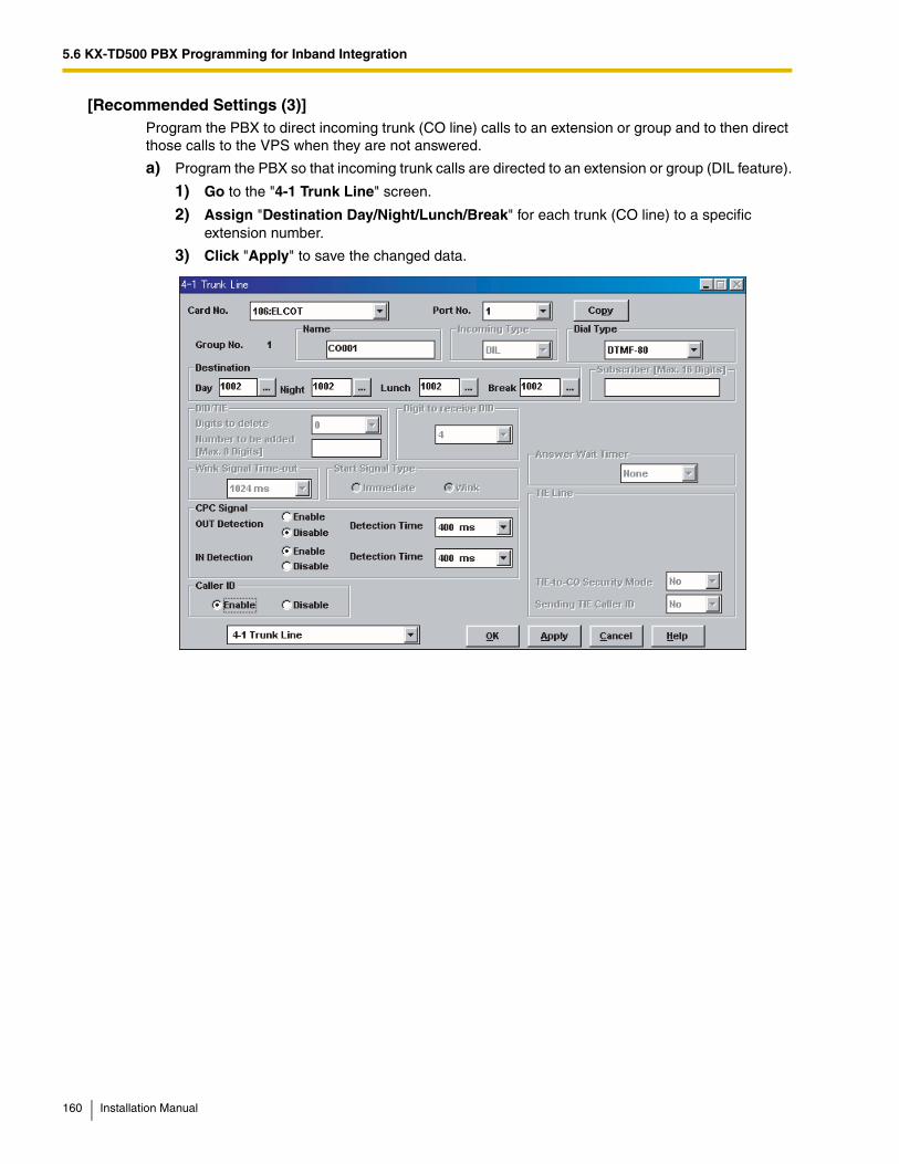
5.6 KX-TD500 PBX Programming for Inband Integration
[Recommended Settings (3)]Program the PBX to direct incoming trunk (CO line) calls to an extension or group and to then direct those calls to the VPS when they are not answered.
a) Program the PBX so that incoming trunk calls are directed to an extension or group (DIL feature).
1) Go to the "4-1 Trunk Line" screen.
2) Assign "Destination Day/Night/Lunch/Break" for each trunk (CO line) to a specific extension number.
3) Click "Apply" to save the changed data.
160 Installation Manual
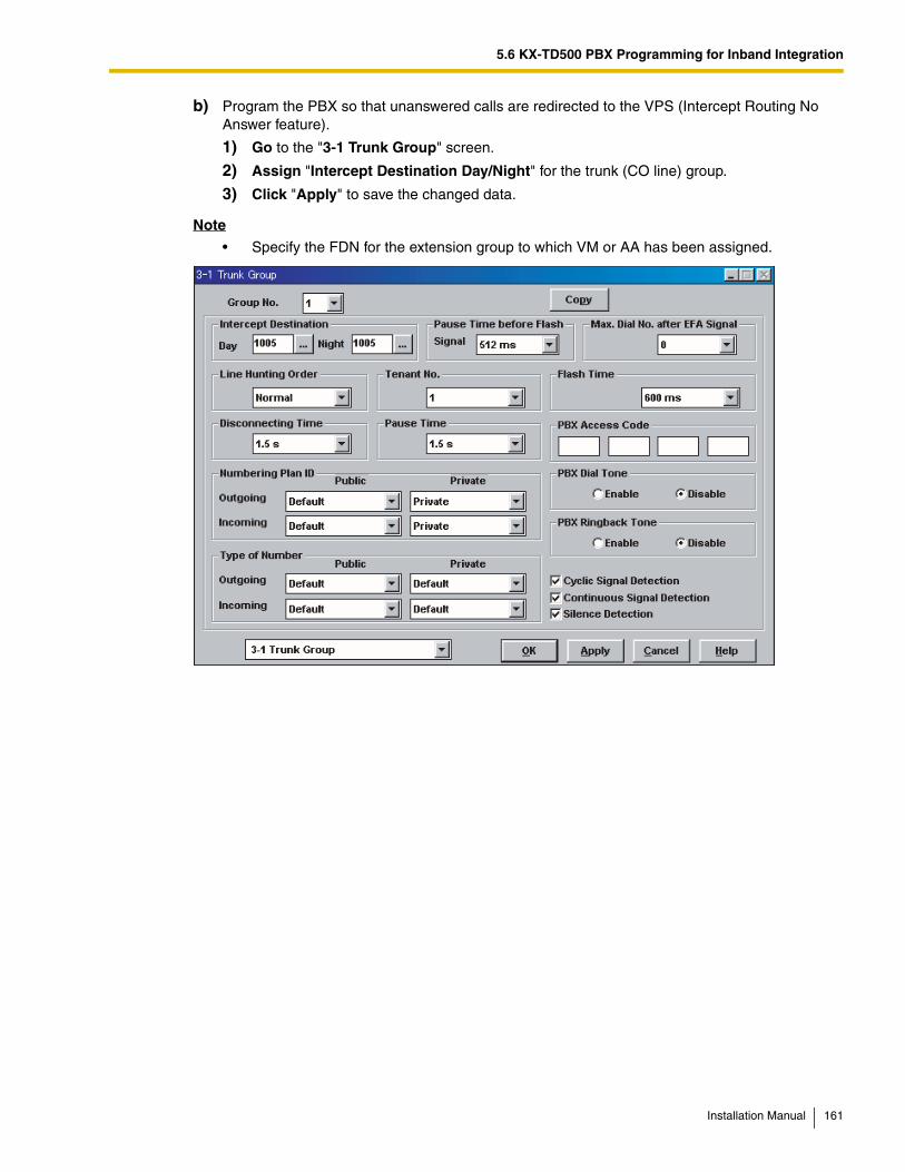
5.6 KX-TD500 PBX Programming for Inband Integration
b) Program the PBX so that unanswered calls are redirected to the VPS (Intercept Routing No Answer feature).
1) Go to the "3-1 Trunk Group" screen.
2) Assign "Intercept Destination Day/Night" for the trunk (CO line) group.
3) Click "Apply" to save the changed data.
Note
• Specify the FDN for the extension group to which VM or AA has been assigned.
Installation Manual 161
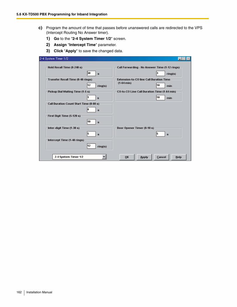
5.6 KX-TD500 PBX Programming for Inband Integration
c) Program the amount of time that passes before unanswered calls are redirected to the VPS (Intercept Routing No Answer timer).
1) Go to the "2-4 System Timer 1/2" screen.
2) Assign "Intercept Time" parameter.
3) Click "Apply" to save the changed data.
162 Installation Manual
5.7 KX-TA Series PBX Programming for Inband Integration
5.7 KX-TA Series PBX Programming for Inband IntegrationNote
• The KX-TA824 can also be programmed via PC using the Operating and Maintenance Tool. Refer to 5.4 KX-TA824 PBX Programming for Inband Integration for more information.
• For KX-TA1232 programming, refer to 5.5 KX-TD Series PBX Programming for Inband Integration.
APT Integration is recommended when using the VPS with a KX-TA series PBX, however, Inband Integration is necessary when:
• the PBX has available SLT ports but no available APT ports.
• the software version of the KX-TA series PBX do not support APT Integration.
Note
• If the PBX is programmed to use 2-digit extension numbers, DTMF Integration is not possible. Program the PBX to use 3-digit extension numbers using System Program [009].
1. Enable System Program [102] for each extension connected to the VPS.
This parameter is used to tell the PBX which extensions are connected to the VPS. Ports with this parameter enabled can receive Follow-on ID and DTMF Signaling (busy, answered, disconnect, etc.) if the Voice Mail Integration and Touchtone Integration features are also enabled.
2. Enable System Program [103] to turn on DTMF Integration. On extensions with the Voice Mail port parameter enabled, the PBX can send DTMF signals to indicate call status; this increases VPS efficiency. Codes apply to all transferred calls; trunk (CO line) calls only indicate a disconnection (provided the PBX is programmed for CPC Detection, and the Telephone Company sends the CPC signal). Refer to the Sequence Codes in 5.2.3 PBX Interface Parameters.
3. Put all extensions connected to the VPS into the same extension group using System Program [600].
Reserve this extension group for these extensions! Do not mix other extensions into this group.
4. Enable hunting for the VPS extension groups using System Program [100].
5. Set the hunting type for the VPS extension groups to "Circular" using System Program [101].
6. At every VPS extension, temporarily connect an SLT or test set, go off-hook and dial 7301# to turn on Data Line Security. This prevents the PBX from sending Executive Override or Call Waiting tones to those extensions. We recommend that all Voice Mail port extensions have this feature enabled to avoid interruption during recording.
7. Select the appropriate trunk (CO line) feature settings depending on how your customer plans to use the VPS: a) to answer all incoming calls, b) as an operator backup, or c) to only answer calls
Installation Manual 163
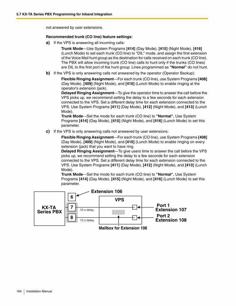
5.7 KX-TA Series PBX Programming for Inband Integration
not answered by user extensions.
Recommended trunk (CO line) feature settings:
a) If the VPS is answering all incoming calls:
Trunk Mode—Use System Programs [414] (Day Mode), [415] (Night Mode), [416] (Lunch Mode) to set each trunk (CO line) to "DIL" mode, and assign the first extension of the Voice Mail hunt group as the destination for calls received on each trunk (CO line). The PBX will allow incoming trunk (CO line) calls to hunt only if the trunks (CO lines) are DIL to the first port of the hunt group. Lines programmed as "Normal" do not hunt.
b) If the VPS is only answering calls not answered by the operator (Operator Backup):
Flexible Ringing Assignment—For each trunk (CO line), use System Programs [408] (Day Mode), [409] (Night Mode), and [410] (Lunch Mode) to enable ringing at the operator's extension (jack).Delayed Ringing Assignment—To give the operator time to answer the call before the VPS picks up, we recommend setting the delay to a few seconds for each extension connected to the VPS. Set a different delay time for each extension connected to the VPS. Use System Programs [411] (Day Mode), [412] (Night Mode), and [413] (Lunch Mode).Trunk Mode—Set the mode for each trunk (CO line) to "Normal". Use System Programs [414] (Day Mode), [415] (Night Mode), and [416] (Lunch Mode) to set this parameter.
c) If the VPS is only answering calls not answered by user extensions:
Flexible Ringing Assignment—For each trunk (CO line), use System Programs [408] (Day Mode), [409] (Night Mode), and [410] (Lunch Mode) to enable ringing on every extension (jack) that you want to have ring.Delayed Ringing Assignment—To give users time to answer the call before the VPS picks up, we recommend setting the delay to a few seconds for each extension connected to the VPS. Set a different delay time for each extension connected to the VPS. Use System Programs [411] (Day Mode), [412] (Night Mode), and [413] (Lunch Mode).Trunk Mode—Set the mode for each trunk (CO line) to "Normal". Use System Programs [414] (Day Mode), [415] (Night Mode), and [416] (Lunch Mode) to set this parameter.
7
6
8
KX-TA Series PBX
VPS Port 1Extension 107 Port 2Extension 108
Extension 106
Mailbox for Extension 106
10 s delay
15 s delay
164 Installation Manual
Section 6
Configuring the System
This section explains how to configure the VPS for basic operation.
Installation Manual 165
6.1 Starting Up
6.1 Starting Up
6.1.1 Before Programming
Careful preparation before you begin programming the VPS will make the programming and customization process easier for you and the customer.
1. Determine the customer's needs.
– Work with the owner/supervisor and Message Manager to build the Custom Service Greetings, Holiday Greetings, etc.
– Decide which ports/trunks (CO lines) should be answered by which greetings.
– Confirm the software level of the PBX to make sure it is compatible with the features the customer wishes to use.
2. While programming the VPS with KX-TVA Maintenance Console, make sure subscribers do not change any of their mailbox settings, otherwise programmed settings may not be saved properly.
3. Work with the Message Manager (perhaps a receptionist or supervisor) to make sure he or she understands the system as well as his or her responsibilities as the Message Manager. This will save you time in the long run.
– Show the Message Manager how to record system greetings. Refer to 7.6 Recording Messages in the Subscriber's Manual.
– Show the Message Manager how to transfer General Delivery Mailbox messages. Refer to 7.2 Managing the General Delivery Mailbox in the Subscriber's Manual.
6.1.2 Quick Setup
The Quick Setup utility allows you to set essential VPS parameters quickly and easily. It is particularly useful when configuring the VPS for the first time or after initializing the VPS.
The following settings can be programmed with the Quick Setup utility:
– System Security settings
– PBX Environment settings
– Mailbox settings
– Port/Trunk settings
– Date and Time setting
Note
• Set the desired parameters in each screen then click "Next" or "Back" to go to the desired screen.
• Each screen of the Quick Setup utility must be completed in order for the settings to take effect.
• The screen shots in this section are examples of the KX-TVA200.
• Settings shown in the screen shots in this section are examples only and may vary depending on the type or settings of the connected PBX, the software version, etc.
166 Installation Manual
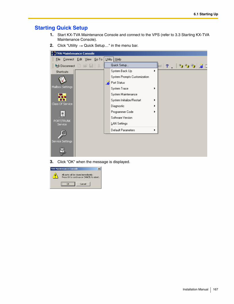
6.1 Starting Up
Starting Quick Setup1. Start KX-TVA Maintenance Console and connect to the VPS (refer to 3.3 Starting KX-TVA
Maintenance Console).
2. Click "Utility Quick Setup…" in the menu bar.
3. Click "OK" when the message is displayed.
Installation Manual 167
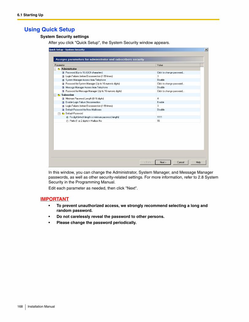
6.1 Starting Up
Using Quick SetupSystem Security settings
After you click "Quick Setup", the System Security window appears.
In this window, you can change the Administrator, System Manager, and Message Manager passwords, as well as other security-related settings. For more information, refer to 2.8 System Security in the Programming Manual.
Edit each parameter as needed, then click "Next".
IMPORTANT• To prevent unauthorized access, we strongly recommend selecting a long and
random password.
• Do not carelessly reveal the password to other persons.
• Please change the password periodically.
168 Installation Manual
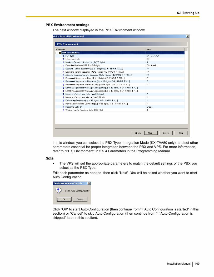
6.1 Starting Up
PBX Environment settings
The next window displayed is the PBX Environment window.
In this window, you can select the PBX Type, Integration Mode (KX-TVA50 only), and set other parameters essential for proper integration between the PBX and VPS. For more information, refer to "PBX Environment" in 2.5.4 Parameters in the Programming Manual.
Note
• The VPS will set the appropriate parameters to match the default settings of the PBX you select as the PBX Type.
Edit each parameter as needed, then click "Next". You will be asked whether you want to start Auto Configuration.
Click "OK" to start Auto Configuration (then continue from "If Auto Configuration is started" in this section) or "Cancel" to skip Auto Configuration (then continue from "If Auto Configuration is skipped" later in this section).
Installation Manual 169
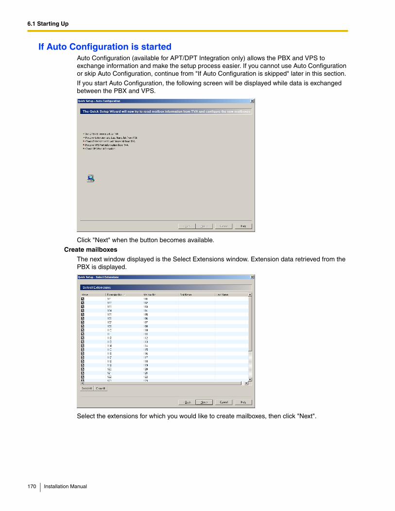
6.1 Starting Up
If Auto Configuration is startedAuto Configuration (available for APT/DPT Integration only) allows the PBX and VPS to exchange information and make the setup process easier. If you cannot use Auto Configuration or skip Auto Configuration, continue from "If Auto Configuration is skipped" later in this section.
If you start Auto Configuration, the following screen will be displayed while data is exchanged between the PBX and VPS.
Click "Next" when the button becomes available.
Create mailboxes
The next window displayed is the Select Extensions window. Extension data retrieved from the PBX is displayed.
Select the extensions for which you would like to create mailboxes, then click "Next".
170 Installation Manual
6.1 Starting Up
Note
• Each extension name retrieved from the PBX is stored in the "Last Name" field of the respective subscriber's Mailbox Settings. Extension names can be retrieved from the following PBXs: KX-TDA series PBXs (MPR version 2.0 or higher)KX-TD500 with software production date code 040901 or later.
• Mailboxes will be created during Auto Configuration. The number of digits used for mailbox numbers is 2 to 5 digits, depending on PBX programming. The Message Manager mailbox (General Delivery Mailbox) number will be 98, 998, 9998, or 99998. The System Manager mailbox number will be 99, 999, 9999, or 99999. If both 3-digit and 4-digit extension numbers are used by the PBX, the VPS will use 4-digit mailbox numbers. When creating mailbox numbers for 3-digit extensions, a "0" will be added to the end of each mailbox number.
Example:
Extension Numbers
201 202 203 2000 2001 2002
Mailbox Numbers
201020202030200020012002
Installation Manual 171
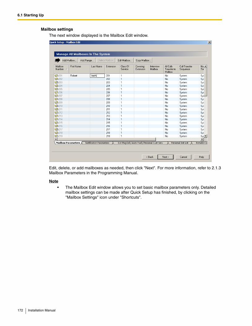
6.1 Starting Up
Mailbox settings
The next window displayed is the Mailbox Edit window.
Edit, delete, or add mailboxes as needed, then click "Next". For more information, refer to 2.1.3 Mailbox Parameters in the Programming Manual.
Note
• The Mailbox Edit window allows you to set basic mailbox parameters only. Detailed mailbox settings can be made after Quick Setup has finished, by clicking on the "Mailbox Settings" icon under "Shortcuts".
172 Installation Manual
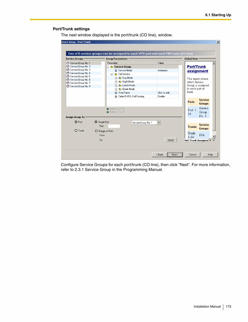
6.1 Starting Up
Port/Trunk settings
The next window displayed is the port/trunk (CO line), window.
Configure Service Groups for each port/trunk (CO line), then click "Next". For more information, refer to 2.3.1 Service Group in the Programming Manual.
Installation Manual 173

6.1 Starting Up
Date and Time setting
The last window displayed is the date and time setting window.
Set the date and time, then click "Finish".
174 Installation Manual
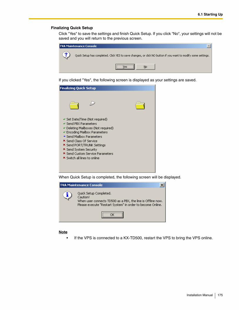
6.1 Starting Up
Finalizing Quick Setup
Click "Yes" to save the settings and finish Quick Setup. If you click "No", your settings will not be saved and you will return to the previous screen.
If you clicked "Yes", the following screen is displayed as your settings are saved.
When Quick Setup is completed, the following screen will be displayed.
Note
• If the VPS is connected to a KX-TD500, restart the VPS to bring the VPS online.
Installation Manual 175
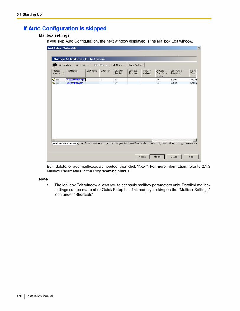
6.1 Starting Up
If Auto Configuration is skippedMailbox settings
If you skip Auto Configuration, the next window displayed is the Mailbox Edit window.
Edit, delete, or add mailboxes as needed, then click "Next". For more information, refer to 2.1.3 Mailbox Parameters in the Programming Manual.
Note
• The Mailbox Edit window allows you to set basic mailbox parameters only. Detailed mailbox settings can be made after Quick Setup has finished, by clicking on the "Mailbox Settings" icon under "Shortcuts".
176 Installation Manual
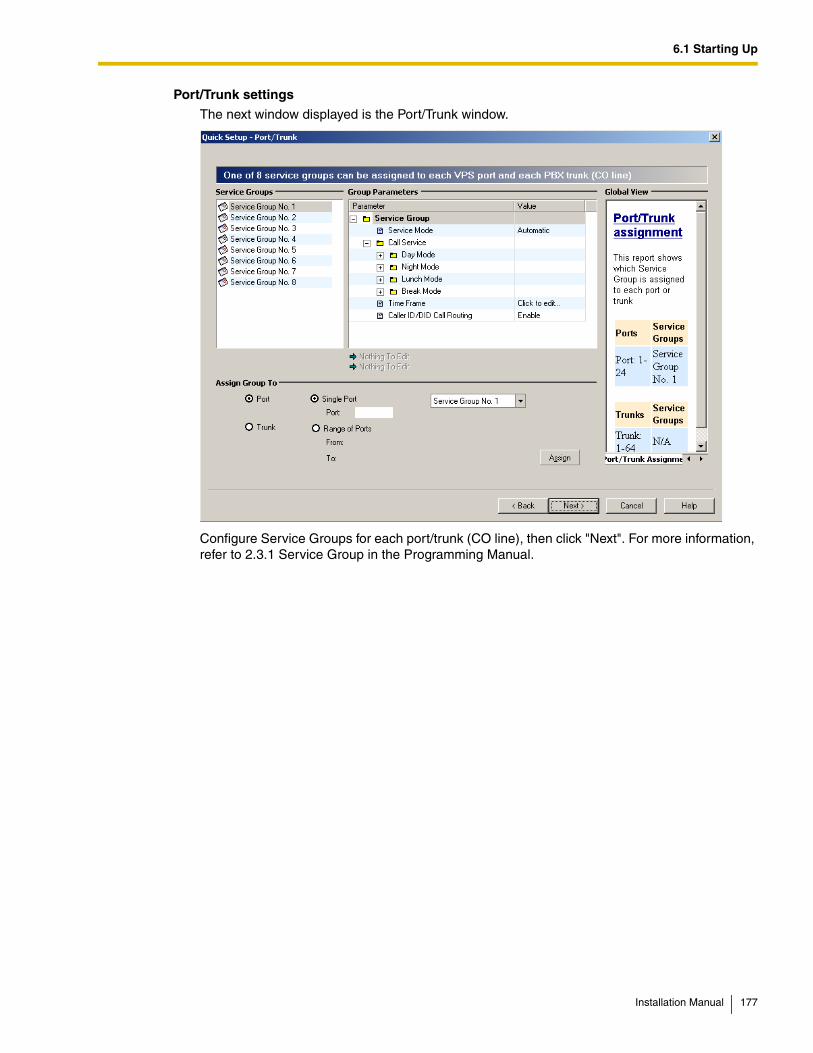
6.1 Starting Up
Port/Trunk settings
The next window displayed is the Port/Trunk window.
Configure Service Groups for each port/trunk (CO line), then click "Next". For more information, refer to 2.3.1 Service Group in the Programming Manual.
Installation Manual 177
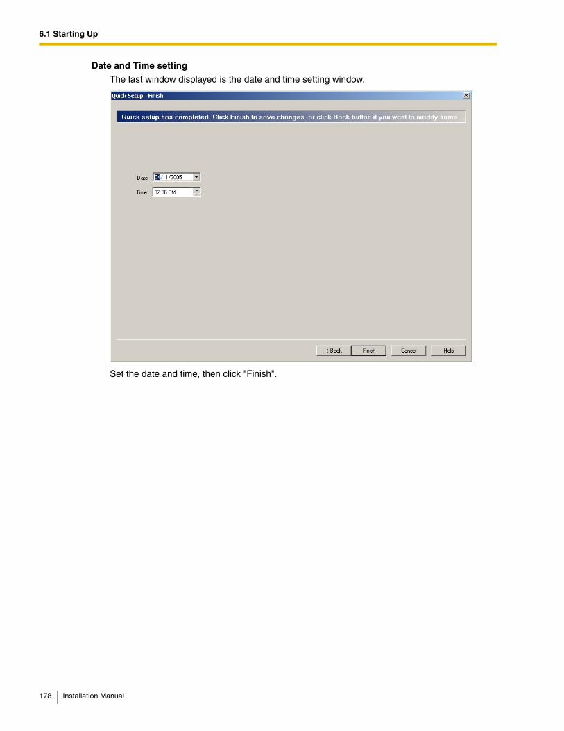
6.1 Starting Up
Date and Time setting
The last window displayed is the date and time setting window.
Set the date and time, then click "Finish".
178 Installation Manual

6.1 Starting Up
Finalizing Quick Setup
Click "Yes" to save the settings and finish Quick Setup. If you click "No", your settings will not be saved and you will return to the previous screen.
If you clicked "Yes", the following screen is displayed as your settings are saved.
When Quick Setup is completed, the following screen will be displayed.
Note
• If the VPS is connected to a KX-TD500, restart the VPS to bring the VPS online.
Installation Manual 179

6.1 Starting Up
180 Installation Manual
Section 7
System Maintenance
This section describes how to perform common maintenance procedures.
Installation Manual 181
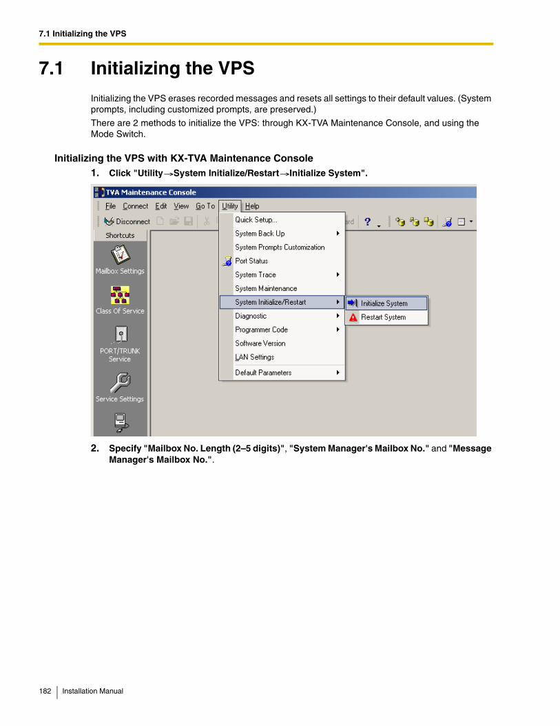
7.1 Initializing the VPS
7.1 Initializing the VPSInitializing the VPS erases recorded messages and resets all settings to their default values. (System prompts, including customized prompts, are preserved.)
There are 2 methods to initialize the VPS: through KX-TVA Maintenance Console, and using the Mode Switch.
Initializing the VPS with KX-TVA Maintenance Console1. Click "Utility System Initialize/Restart Initialize System".
2. Specify "Mailbox No. Length (2–5 digits)", "System Manager's Mailbox No." and "Message Manager's Mailbox No.".
182 Installation Manual
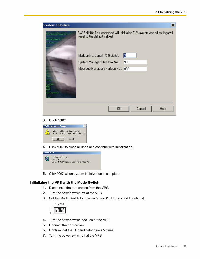
7.1 Initializing the VPS
3. Click "OK".
4. Click "OK" to close all lines and continue with initialization.
5. Click "OK" when system initialization is complete.
Initializing the VPS with the Mode Switch1. Disconnect the port cables from the VPS.
2. Turn the power switch off at the VPS.
3. Set the Mode Switch to position 5 (see 2.3 Names and Locations).
4. Turn the power switch back on at the VPS.
5. Connect the port cables.
6. Confirm that the Run Indicator blinks 5 times.
7. Turn the power switch off at the VPS.
01
1 2 3 4
Installation Manual 183
7.1 Initializing the VPS
8. Set the Mode Switch to position 0.
9. Turn the power switch back on at the VPS.
Note
• The execution time for the initialization may differ each time it is performed because of system capacity and system programs. Generally, initialization will take about 10 min to accomplish.
184 Installation Manual
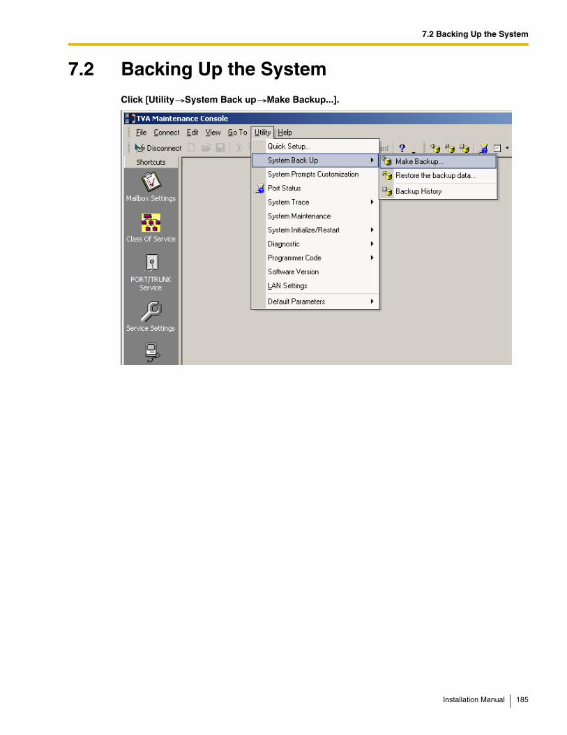
7.2 Backing Up the System
7.2 Backing Up the SystemClick [Utility System Back up Make Backup...].
Installation Manual 185
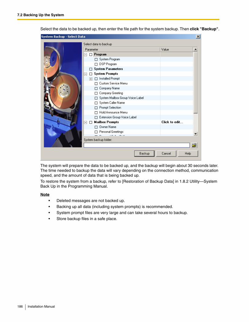
7.2 Backing Up the System
Select the data to be backed up, then enter the file path for the system backup. Then click "Backup".
The system will prepare the data to be backed up, and the backup will begin about 30 seconds later. The time needed to backup the data will vary depending on the connection method, communication speed, and the amount of data that is being backed up.
To restore the system from a backup, refer to [Restoration of Backup Data] in 1.8.2 Utility—System Back Up in the Programming Manual.
Note
• Deleted messages are not backed up.
• Backing up all data (including system prompts) is recommended.
• System prompt files are very large and can take several hours to backup.
• Store backup files in a safe place.
186 Installation Manual
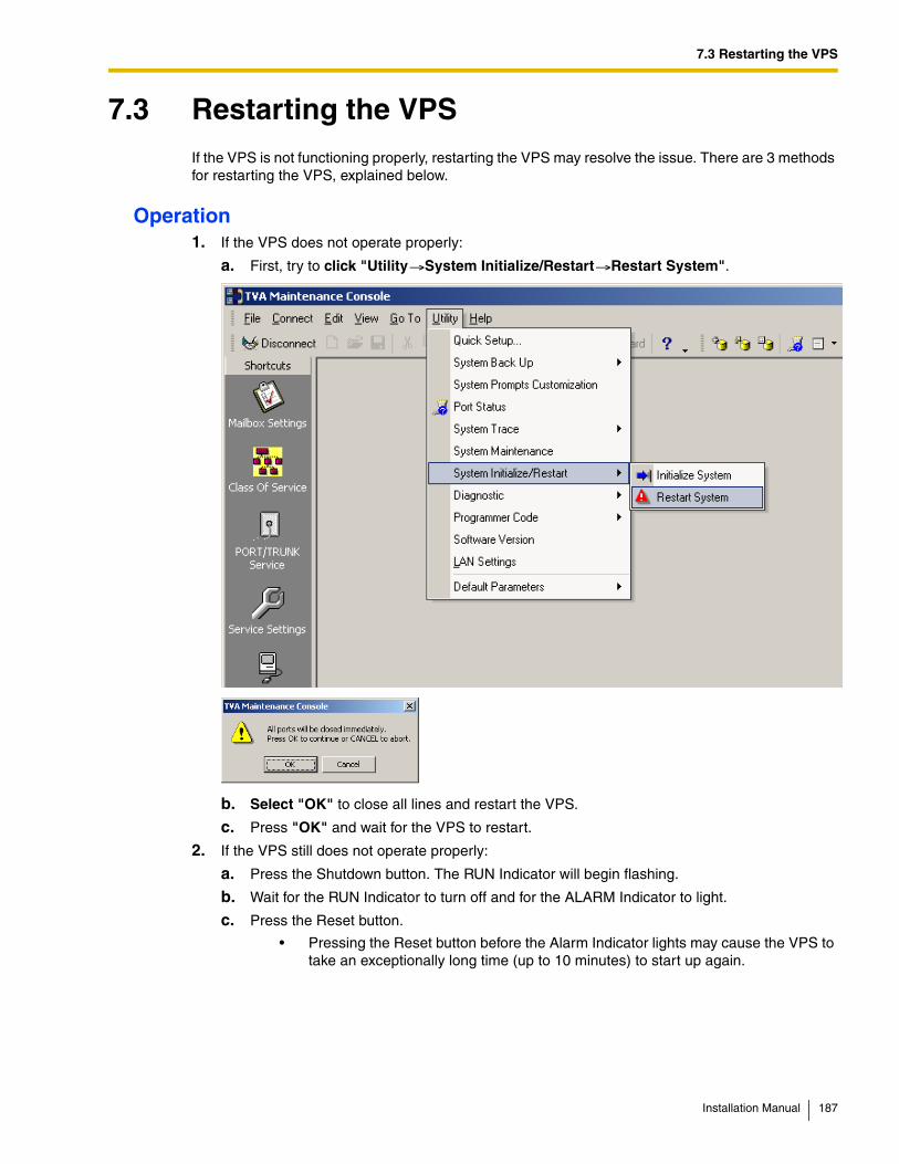
7.3 Restarting the VPS
7.3 Restarting the VPSIf the VPS is not functioning properly, restarting the VPS may resolve the issue. There are 3 methods for restarting the VPS, explained below.
Operation1. If the VPS does not operate properly:
a. First, try to click "Utility System Initialize/Restart Restart System".
b. Select "OK" to close all lines and restart the VPS.
c. Press "OK" and wait for the VPS to restart.
2. If the VPS still does not operate properly:
a. Press the Shutdown button. The RUN Indicator will begin flashing.
b. Wait for the RUN Indicator to turn off and for the ALARM Indicator to light.
c. Press the Reset button.
• Pressing the Reset button before the Alarm Indicator lights may cause the VPS to take an exceptionally long time (up to 10 minutes) to start up again.
Installation Manual 187
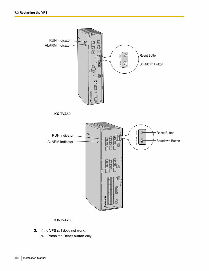
7.3 Restarting the VPS
KX-TVA50
KX-TVA200
3. If the VPS still does not work:
a. Press the Reset button only.
RUN Indicator
ALARM Indicator
Reset Button
Shutdown Button
SH
UTD
OW
NR
ES
ET
SH
UTD
OW
NR
ES
ET
RUN Indicator
ALARM Indicator
Reset Button
Shutdown Button
188 Installation Manual
Glossary
Alternate Extension GroupThe extensions assigned to an Alternate Extension Group receive transferred calls via the sequence specified as the group's "Alternate Extension Transfer Sequence".
APT IntegrationDigital integration between the VPS and certain Panasonic PBXs. Requires upgraded software in the PBX. When the VPS and PBX use APT Integration, voices are sent using analog technology, and data is sent digitally. Depending on the model and/or the software version of the connected PBX, you may not be able to utilize certain features available only with APT Integration. For more information, consult your dealer.
Auto ConfigurationAvailable with APT/DPT Integration only. Simplifies initial system setup by reading information from the PBX and automatically creating mailboxes in the VPS to correspond to the extensions connected to the PBX. Auto Configuration can be initiated with the appropriate Mode Switch setting or by System Administration (Quick Setup).
Auto ForwardingAllows unplayed messages to be copied or moved to another mailbox.
Auto ReceiptAllows a subscriber or the System Manager to receive a message to confirm the reception of sent messages to other subscribers.
Automated AttendantThe Automated Attendant feature of the VPS requests the caller to enter an extension number and then the VPS dials the number. If there is no answer or the line is busy, the caller is given certain options, including the option to leave a message in a mailbox. This is the advantage of calling an extension indirectly through the Automated Attendant rather than calling it directly.
Automatic Log-inAvailable with APT/DPT Integration only. Allows subscribers to access their mailboxes directly without entering their mailbox numbers. Subscribers can access their mailboxes directly from their extensions or from outside phones by dialing a preprogrammed telephone number (either a DID number or a telephone number that reaches the PBX via a preprogrammed trunk [CO line]) or by calling the VPS from a preprogrammed telephone number (Caller ID number).
Installation Manual 189
Autoplay New MessageThe VPS plays new messages automatically when a subscriber, the System Manager, or the Message Manager logs in to his or her mailbox.
BookmarkEnables a subscriber, the System Manager, or the Message Manager to set a specific point (Bookmark) in a message and easily resume playback later from that point.
Call BlockingAllows subscribers to have their calls handled by the Incomplete Call Handling Service without ringing at their extensions.
Call ScreeningAllows subscribers to screen calls. The VPS prompts the caller with the message "Record your name at the tone", and records the caller's name. The caller is put on hold while the VPS calls the subscriber and plays back the caller's name. The subscriber can then decide whether to take the call or not.
Called Party ID(Sometimes referred to as Follow-On ID) Allows the PBX to dial extra digits to bring the caller directly to a specified mailbox, rather than to the General Delivery Mailbox.
Caller ID CallbackAvailable with APT/DPT Integration only. Enables a subscriber to use the Caller ID number information included with a message to call back the message sender without dialing the caller's telephone number.
Caller ID Call RoutingAvailable with APT/DPT Integration only. The VPS automatically sends calls from preprogrammed Caller ID numbers to a specified extension, mailbox (including Mailbox Group) or Custom Service.
Caller Name Announcement (System/Personal) Available with APT/DPT Integration only. The VPS announces prerecorded Caller ID caller names when:(1) subscribers listen to messages received from preprogrammed telephone numbers left in their mailboxes.(2) the VPS transfers calls from preprogrammed telephone numbers to subscribers (Caller ID Screening).(3) the VPS pages subscribers by intercom (Intercom Paging). Caller names can be recorded and played for all subscribers (system) or can be recorded by individual subscribers and played for their own calls only (personal). If the same Caller ID number is programmed for both System and Personal Caller Name Announcements, the VPS will use the caller name recorded by the subscriber.
190 Installation Manual
Company GreetingA maximum of 32 Company Greetings can be recorded to greet callers. One (or System Greeting or none) can be selected for each Day, Night, Lunch, Break, and Holiday service based on a port and trunk (CO line).
Company NameThis is played by the VPS to the intended receiver of an External Delivery Message when he or she is unable to enter correctly the password (if a password is required to listen to the message). This helps him or her to realize where the call came from and contact the message sender if necessary.
Covering ExtensionAllows subscribers to set another extension as the destination for their calls. Callers can be directed to the covering extension either by the Incomplete Call Handling feature, or by pressing [0] while listening to a subscriber's personal greeting message or while leaving a message.
Custom Service BuilderAllows the System Administrator to create Custom Services visually, using KX-TVA Maintenance Console. Each Custom Service and its functions can be edited and arranged using a familiar drag-and-drop interface.
Custom ServiceAllows callers to perform specific functions by pressing dial buttons on their telephones while listening to voice guidance (Custom Service Menus). Custom Services allow callers to connect themselves to an extension, mailbox, Mailbox Group, operator, fax machine, etc., without the assistance of an operator. The System Administrator can create a maximum of 100 Custom Services.
Default Mailbox TemplateIs used as a template when the System Administrator creates consecutive mailboxes. It enables the System Administrator to apply basic settings (Mailbox Parameters, Message Waiting Notification, External Message Delivery, Auto Forwarding) to multiple mailboxes simultaneously.
Default SettingA parameter defined for the VPS at the factory which can be changed through system programming by the System Administrator or the System Manager.
Delayed RingingThere are 2 kinds of delayed ringing applications. (1)The VPS is used as the no-answer destination for the Intercept Routing feature of your PBX. (2) DIL 1:N (trunk [CO line] to several extensions) terminates on telephones and VPS ports. To give the telephone users a chance to answer calls, the VPS lines should be programmed for delayed ringing. Otherwise, the VPS will answer the calls immediately.
Installation Manual 191
Delete Message ConfirmationThe VPS requests confirmation from the subscriber before erasing a message left in his or her mailbox.
Delivery TimeThe time specified by the subscriber for the VPS to deliver a prerecorded message. Subscribers can specify the delivery time when leaving messages for other subscribers or when sending a message via External Message Delivery.
DID Call RoutingAvailable with DPT Integration only. The VPS automatically sends calls from preprogrammed DID numbers to a specified extension, mailbox (including Mailbox Group) or Custom Service.
DPT IntegrationDigital integration between the VPS and certain Panasonic PBXs. Requires upgraded software in the PBX. When the VPS and PBX use DPT Integration, voices and data are sent digitally. Depending on the model and/or the software version of the connected PBX, you may not be able to utilize certain features available only with DPT Integration. For more information, consult your dealer.
DTMFDual Tone Multi Frequency. Commonly referred to as touchtone.
E-mail IntegrationAllows subscribers and the Message Manager to receive notification by e-mail when they receive new messages. Subscribers can also have the voice message attached to the e-mail notification if the System Administrator has enabled this feature for their mailboxes.
External Delivery MessageA message recorded by a subscriber and then delivered to outside parties and/or extensions. The VPS dials the outside telephone number or extension number and plays the message for the recipient. The message can be delivered immediately or at a specified time.
External Message Delivery ListA preprogrammed list of outside parties and extensions that can be used to deliver an External Delivery Message to several recipients in one operation. Each subscriber can create 2 External Message Delivery Lists. Each list can have 8 destinations.
External Message Delivery RetryDetermines how many times the VPS will attempt to deliver an External Delivery Message when the called line (recipient) is busy or does not answer.
Fast ForwardAllows a subscriber to fast forward through a message in 4 second intervals.
192 Installation Manual
Follow-On ID(see "Called Party ID")
General Delivery MailboxA special mailbox that is maintained by the Message Manager. If a caller does not have a DTMF-compatible telephone, the caller cannot dial numbers in order to connect himself or herself to an extension or mailbox. Callers who do not dial any numbers can be directed to the General Delivery Mailbox. Periodically (daily is best), the Message Manager should transfer messages in the General Delivery Mailbox to the appropriate subscriber mailboxes.
Hash SignThe [#] key on the telephone keypad. Also known as the "pound sign".
Immediate ReplyAllows the message recipient to reply to a message without specifying the extension number or the mailbox number of the sender.
Inband IntegrationWhen the VPS and PBX use Inband Integration, voices are sent using analogue technology, and data is sent using analogue DTMF tones. The PBX informs the VPS of the status of extensions by sending DTMF tones and Call Progress tones to the VPS. Many features, such as Intercom Paging, Live Call Screening (LCS), etc., are not available with Inband Integration.
Incomplete Call Handling ServiceCalls are considered incomplete when is the called extension does not answer, is busy, or has set Call Blocking.Incomplete Call Handling can handle calls in 7 different ways. Each subscriber can specify the options available to callers when their calls are incomplete.(1) leave a message in the subscriber's mailbox(2) transfer to the subscriber's Covering Extension(3) Intercom Paging (notify the subscriber by paging the subscriber)(4) Beeper Access (notify the subscriber by paging the subscribers beeper)(5) transfer to Custom Service(6) transfer to operator(7) return the caller to the top menu, allowing the caller to call another extension
Intercept Routing—No AnswerA PBX feature that transfers an unanswered call to another extension or to the VPS.
Installation Manual 193
Intercom PagingAvailable with APT/DPT Integration only. If a subscriber has set Intercom Paging, the VPS will page the subscriber and announce that he or she is receiving a call. The VPS can announce prerecorded caller names using the Caller Name Announcement feature, or prompt the caller to record his or her name and announce the recorded name. Pages can be heard through PT speakers or through external speakers connected to the PBX.
Interview ServiceAllows the VPS to "interview" a caller by playing a series of prerecorded questions and recording the caller's responses. Subscribers are able to record questions directly into their interview mailboxes. After a caller records his or her answers, the Message Waiting Lamp turns on at the subscriber's telephone. This feature is very useful for claims departments, order desks, job applications, etc.
KeypadThe dial keys ([0]–[9], [ ], [#]) on a telephone.
LCDLiquid crystal display
Live Call Screening (LCS)Available with APT/DPT Integration only. Allows the subscriber to use his or her PT to monitor incoming calls as messages are being recorded. The subscriber has the option of answering calls while monitoring or allowing the message to be recorded without interruption.
Logical Extension (All Calls Transfer to Mailbox)An extension that always receives calls directly into its mailbox. This feature is used by subscribers who are often unavailable or who do not have a telephone.
Mailbox Capacity (recording time)The total length of time for all messages that can be recorded in a subscriber's mailbox. The System Administrator or System Manager can set each subscriber's maximum mailbox capacity. Each subscriber's mailbox capacity is determined by COS.
Mailbox Capacity WarningAllows the VPS to alert subscribers when recording time for their mailboxes are running low. The warning announcement will be heard at the beginning of Subscriber's Service.
Mailbox GroupA preprogrammed list of subscriber mailboxes that can be used (by any subscriber) to deliver a message to several recipients in one operation. Up to 20 Mailbox Groups can be created.
194 Installation Manual
Mailbox NumberNormally the same number as the corresponding subscriber's extension number.
Message Envelope SettingSpecifies when message envelopes (message date and time, name of the person who recorded or transferred the message, telephone number of the caller) are announced. Envelopes can be played back before or after messages automatically, or only when the subscriber presses [2] [3] during or after message playback.
Message ManagerMailbox 998. The person who takes care of message-related maintenance, such as General Delivery Mailbox maintenance, and recording and deleting messages (System Prompts, Company Greetings, Custom Service Menus, System Caller Names, etc.)
Message RecoveryAllows a subscriber to change the status of a message from "deleted" to "old", preventing the message from being permanently deleted.
Message Retention TimeDetermines the number of days before a message is automatically deleted.New Message Retention Time: Determines when new (unplayed) messages are deleted. Saved Message Retention Time: Determines when old (played) messages are deleted.
Message Retrieval OrderWhen a subscriber has several messages in his or her mailbox, determines whether messages are played back from newest to oldest (Last In First Out [LIFO] or from oldest to newest First In First Out [FIFO]).
Message TransferAllows a subscriber to reroute a message to another mailbox and add his or her comments to the message if necessary. Receipt messages and messages originally marked as "private" cannot be transferred.
Message Waiting LampThe lamp on a PT that lights when there are messages in the extension user's mailbox.
Message Waiting NotificationNotifies subscribers and the Message Manager when they have received messages, by lighting the Message Waiting Lamp on their PTs, by calling a preprogrammed telephone number, or by paging a beeper.
Installation Manual 195
Multilingual Selection MenuAllows callers to select the language they would like to hear for voice guidance (system prompts). 3 languages can be selected for the Multilingual Selection Menu of the KX-TVA50; 5 languages for the KX-TVA200.
Non-SubscriberA caller to the VPS who does not own a mailbox.
Notification Method(see "Message Waiting Notification")
On Hold Announcement MenuAllows callers in a queue to listen to the prerecorded announcement or music while they are on hold.
One-touch Two-way Transfer (One-touch TWT)Available with KX-TDA series and KX-TAW series PBXs using DPT Integration only. Allows a subscriber to record his or her telephone conversations into another subscriber's mailbox with a one-touch operation.
Operator3 different extensions can be assigned as operators for each time mode. Callers can be directed to an operator when they dial [0], when they have rotary or pulse telephones (and thus cannot dial while listening to VPS prompts), or when certain VPS features are programmed to direct callers to an operator.
Owner's NameEach mailbox has an owner's name (subscriber name), and there are 2 ways that these names are stored in the VPS. First, subscribers can record their own names; the VPS can announces this recorded name during transfers, Intercom Paging, and when callers use the Dialing by Name feature. Second, the System Administrator can assign a text name for each subscriber. This allows callers to dial subscribers extension's by name (Dialing by Name) rather than by number. For example, a caller can dial "S-M-I-T" (Smith) rather than Smith's mailbox number, which can be hard to remember.
PasswordA combination of numbers that protects a subscriber's mailbox from unauthorized access. If forgotten, the System Administrator or the System Manager can clear it so that the subscriber can select a new password.
196 Installation Manual
Personal Custom ServiceSimilar to a Custom Service, allows callers to perform specific functions by pressing dial buttons on their telephones while listening to the subscriber's Personal Greeting Message. A subscriber's Personal Custom Service can allow callers to connect themselves to another extension, mailbox, outside telephone (such as the subscriber's mobile phone), etc., without the assistance of an operator. Each subscriber can create his or her own Personal Custom Service.
Personal GreetingsSubscribers can record 3 greeting messages that greet callers who are directed to their mailboxes. The Personal Greeting heard by callers depends on the status of the subscriber or VPS. No Answer Greeting: Heard by callers when the subscriber does not answer. Busy Signal Greeting: Heard by callers when the subscriber is busy. After Hours Greeting: Heard by callers when the VPS is in night mode.
Personal Greeting for Caller IDAvailable with APT/DPT Integration only. A subscriber can record a maximum of 4 Personal Greeting messages that are played for callers whose telephone numbers (Caller ID numbers) have been assigned to a Personal Greeting for Caller ID. A maximum of 8 Caller ID numbers can be assigned to each greeting.
Personal Group Distribution ListA preprogrammed list of subscriber mailboxes that can be used (by the subscriber who created the list) to deliver a message to several recipients in one operation. Each subscriber can create 4 Personal Group Distribution Lists. Each list can have 40 members.
Personal ProgrammingAlso known as Station Programming. PBX programming that is performed by an extension user to customize his or her extension's settings. In order to user certain VPS features, such as Live Call Screening (LCS), personal programming may be required.
PIN Call RoutingAllows preferred callers to be directed to a specific extension, mailbox, or Custom Service when they enter their assigned PIN.
Playback Volume/Speed ControlAllows subscribers to control playback volume and speed while listening to messages.
PortThe point of connection between the PBX and the VPS.
Pound SignThe [#] key on the telephone keypad. Also known as the "hash sign".
Installation Manual 197
Private MessageA message designated by the sender as private. Private messages cannot be forwarded by the recipient.
Remote Call Forwarding SetAvailable with DPT Integration only. Allows subscribers and the Message Manager to program their extensions from a remote location to forward various types of calls (all calls, no answer, busy, etc.) to a desired extension, or to an outside telephone (Remote Call Forward to CO).
Remote Call Forward to COAvailable with DPT Integration only. Allows subscribers and the Message Manager to program their extensions from a remote location to forward their calls to an outside telephone, if authorized.
RewindAllows a subscriber to replay the last 4 seconds of a message.
Rotary TelephoneA telephone that is not capable of emitting DTMF (touchtone) signals. Callers using rotary telephones will be automatically forwarded to an operator or the General Delivery Mailbox because they cannot dial numbers as directed by the VPS prompts.
Service GroupA group of settings which determine how incoming calls are handled by the VPS. One of 8 call service groups is assigned to each VPS port or PBX trunk (CO line).
Service ModeDetermines if incoming calls are handled by the VPS according to settings made for day mode, night mode, lunch mode, or break mode. The current mode can be changed automatically (either by the VPS or by the time mode settings of the PBX) or can be changed manually by the System Administrator and System Manager. Each Service Group is assigned a Service Mode.
SubscriberA person who has an assigned mailbox.
Subscriber TutorialGuides subscribers through the mailbox configuration process the first time they access their mailboxes. The subscriber's password, owner's name, and No Answer Greeting can be configured using the Subscriber Tutorial.
198 Installation Manual
System AdministrationIncludes system programming, diagnosis, system prompt administration, etc. They are performed by the System Administrator, using a PC running the KX-TVA Maintenance Console software. System Administration can be performed locally (on-site) by connecting to the VPS via USB or LAN, or remotely (off-site) by connecting to the VPS via the optional modem card.
System AdministratorIs the person responsible for programming the most essential VPS settings. Unlike the Message Manager and the System Manager, who use a telephone to perform their duties, the System Administrator uses a PC running the KX-TVA Maintenance Console software to program the VPS. The System Administrator's handbook is the Programming Manual. Only one programming session is possible at a time.
System External Message Delivery Duration TimeSpecifies the maximum telephone connection time allowed for External Message Delivery. Prevents excessive telephone charges.
System ManagerMailbox 999. The person who can perform a subset of the items that can be programmed by the System Administrator. The System Manager, using a telephone connected to the VPS, can create/delete mailboxes, clear subscriber passwords when they are forgotten, set Class of Service parameters, set the System Clock, etc.
System PromptRecorded voice guidance messages that help subscribers and callers use VPS features. Over 1000 prompts are prerecorded in the VPS. The System Administrator and Message Manager can rerecord prompts as necessary.The System Administrator and the Message Manager can turn system prompts on and off as needed. Each system prompt has a unique number.
System ReportThe System Administrator or the System Manager can generate various System Reports to monitor the status of the VPS.
System SecurityBy default, the System Manager and Message Manager cannot access the VPS from their telephones until the System Administrator sets their passwords and allows them to access the VPS via their telephones. The System Manager and Message Manager must always enter their passwords in order to access the VPS.The System Administrator can also choose to set a default password for subscriber's mailboxes. If this setting is enabled, a default password is automatically assigned when mailboxes are created.
Installation Manual 199
Temporary Personal GreetingA special greeting that, if recorded by a subscriber, is heard by callers instead of the subscribers other Personal Greetings. Often used to inform callers of a temporary absence. A common example might be, "This is (name). I'm out of the office this week…".
Time SynchronizationAvailable with DPT Integration only. When the date and time is set for the PBX or when DPT Integration is established, date and time data is sent from the PBX to the VPS.
Timed Reminder SettingAvailable with DPT Integration only. Allows a subscriber to set a Timed Reminder by following system prompts provided by the VPS. Timed Reminder is a PBX feature that is similar to an alarm clock; the telephone will ring at the set time (once or daily) as set by the subscriber or Message Manager.
Toll SaverAllows a subscriber to check his or her mailbox for new messages by calling the VPS from a preprogrammed Caller ID number, by dialing a preprogrammed DID number, or by dialing a telephone number that connects the call to a preprogrammed trunk (CO line) of the PBX. Toll Saver is a cost-saving feature that lets the subscriber know if he or she has new messages by the number of rings heard before the VPS answers the outside call from the subscriber. If the VPS does not answer the call within a preprogrammed time period, the subscriber can disconnect the call and thus avoid telephone charges.
Two-way RecordAvailable with APT/DPT Integration only. Allows a subscriber to record his or her telephone conversations into his or her mailbox.
Two-way TransferAvailable with APT/DPT Integration only. Allows a subscriber to record his or her telephone conversations into another subscriber's mailbox. The subscriber must specify the desired extension number when using this feature.
Unlimited Message LengthAllows a subscriber to record telephone conversations of an unlimited length of time when using Two-way Record and Two-way Transfer. The maximum recording time for other messages will be automatically set to 60 minutes.
Urgent MessageA message designated by the sender as urgent. Urgent messages are played back before other messages when the recipient listen to his or her messages.
200 Installation Manual
VM MenuAvailable with KX-TDA series PBXs using DPT Integration only. Displays VPS text prompts on the display of a compatible PT, allowing the subscriber to operate the VPS by following text prompts and pressing soft buttons and the Navigator Key. Voice prompts are not used.
Voice MailA general term used for messages recorded by the VPS and stored in subscriber mailboxes.
VPSA Voice Processing System, such as the Panasonic KX-TVA50, and KX-TVA200.
Installation Manual 201

202 Installation Manual

Installation Manual 203
Index
Index
Numerics2-Port Digital Expansion Card (KX-TVA503) 482-Port Hybrid Expansion Card (KX-TVA502) 464-Port Digital Expansion Card (KX-TVA204) 56
AAbout the Other Manuals 9Alarm Indicator 36Allowable Relative Humidity vs. Temperature 31APT Integration 23APT Integration (TVA50 only) 21APT/DPT Integration Features 90
BBacking Up the System 185Basic System Construction 14Before Installation 30Before Programming 166
CClosing the Covers 42Compatible PBXs 20Completing the PBX-VPS Connection 124Configuring the System 165Connecting the AC Adaptor 66Connecting to the PBX 60Connection Examples—KX-TVA200 25Connection Examples—KX-TVA50 22
DData—saving the system data to the backup device (SAVE) 185DC IN 38DPT Integration 21, 22, 25
EEnvironmental Requirements (KX-TVA200 only) 31
FF.C.C. REQUIREMENTS AND RELEVANT INFORMATION 6Factory Installed Flash Memory Card (KX-TVA50 only) 38For Future Reference 5Frame Ground Connection 65
GGlossary 189Ground Terminal 38Guidelines for APT/DPT Integration 90
HHard Disk Drive (KX-TVA200 only) 38Hard Disk Drive Usage Environment 31
IIf Auto Configuration is skipped 176If Auto Configuration is started 170Inband Integration (TVA50 only) 21
Inband/No Integration 24Included Items 46, 48, 50, 51, 53, 56, 59Initializing the VPS 182Initializing the VPS During Installation 70Initializing the VPS with KX-TVA Maintenance Console 182Initializing the VPS with the Mode Switch 183Installation 29, 46, 48, 50, 51, 53, 56, 59Installation note 5Installation Overview 39Installation Precautions 30Installer Equipment and Software Requirements 17Installing KX-TVA Maintenance Console 81, 84Installing Optional Cards—KX-TVA200 55Installing Optional Cards—KX-TVA50 45Installing Prompt Data for the VM Menu Feature 103
KKX-TA Series PBX Programming for APT Integration 121KX-TA Series PBX Programming for Inband Integration 163KX-TA824 PBX Programming for APT Integration 104KX-TA824 PBX Programming for Inband Integration 146KX-TD Series PBX Programming for DPT Integration 109KX-TD Series PBX Programming for Inband Integration 151KX-TD Series PBX Programming via the Manager's Extension 109KX-TD1232 Series PBX Programming via the Operating and Maintenance
Tool 112KX-TD500 PBX Programming for DPT Integration 114KX-TD500 PBX Programming for Inband Integration 153KX-TDA and KX-TAW Series PBX Programming for DPT Integration 94KX-TDA and KX-TAW Series PBX Programming for Inband Integration
137KX-TVA Maintenance Console Installation 83KX-TVA200 2, 18, 20, 35, 61, 65KX-TVA50 2, 18, 20, 34, 61, 65
LLAN Connection 63LAN Interface Card (KX-TVA594) 51LAN Port (Optional for KX-TVA50) 38
MMain Unit 14Memory Expansion Card (KX-TVA524) 50Mode Switch 36Modem Card (KX-TVA296) 53, 59Modem Connection 63Modular Plug Connection 61Mounting on a Concrete or Mortar Wall 73Mounting on a Wooden Wall 71
NNames and Locations 34No Integration (TVA50 only) 21Note 9
OOpening the Covers 40Opening/Closing the Covers 40
204 Installation Manual
Index
Operation 187Optional Cards—KX-TVA200 16Optional Cards—KX-TVA50 16Options 16Outside/Inside View 34Overview 21, 82
PPassword Security 83PBX Connections 60PBX Programming for APT/DPT Integration 89PBX Programming for Inband Integration (KX-TVA50 only) 127PC Connection 62Power Switch 38Product service 5
QQuick Setup 166
RRecommendations for System Configuration 18Removing the Dummy Cover Plates 44Removing/Attaching the Front Cover 41Reset Button 36Restarting the VPS 187Run Indicator 36
SSAVE 185Securing the Cables 68Shutdown Button 36Specifications 26Starting KX-TVA Maintenance Console 86Starting Quick Setup 167Starting Up 166System Components 36System Connection Diagram 15System Maintenance 181
TTrademarks 9
UUnpacking 33Updating other Panasonic Drivers 84USB Connection 62USB Port 38Using Quick Setup 168
VVM Link (Currently unavailable) 38Voice Mail Integration 21Voice Processing System Overview 13
WWall Mounting 71Wall Mounting the AC Adaptor 75
Wall Mounting the VPS 71What is APT/DPT Integration? 90When to Use APT/DPT Integration 90When you ship the product 5Wiring Precautions 30
Installation Manual 205
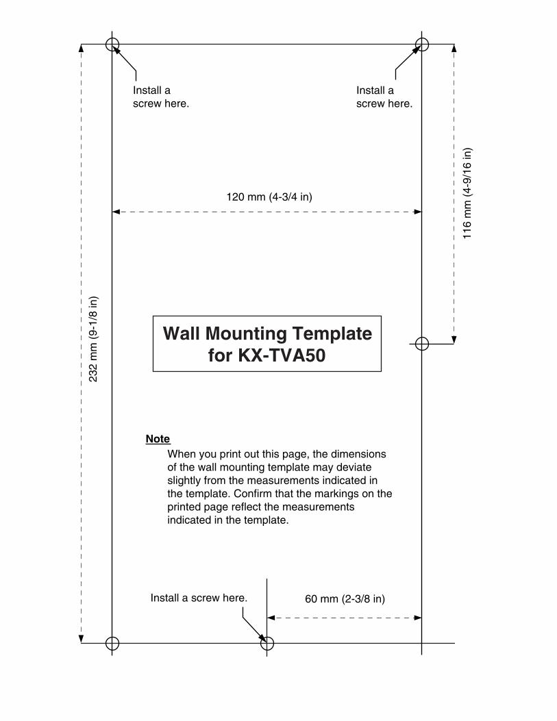
232
mm
(9-
1/8
in)
60 mm (2-3/8 in)
120 mm (4-3/4 in)
116
mm
(4-
9/16
in)
Install a screw here.
Install a screw here.
Install a screw here.
Note
Wall Mounting Templatefor KX-TVA50
When you print out this page, the dimensions of the wall mounting template may deviate slightly from the measurements indicated in the template. Confirm that the markings on the printed page reflect the measurements indicated in the template.
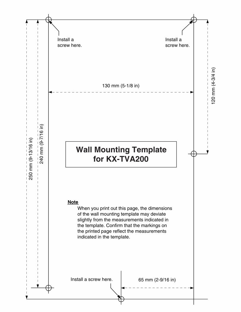
250
mm
(9-
13/1
6 in
)
240
mm
(9-
7/16
in)
65 mm (2-9/16 in)
130 mm (5-1/8 in)
120
mm
(4-
3/4
in)
Install a screw here.
Install a screw here.
Install a screw here.
Note
Wall Mounting Templatefor KX-TVA200
When you print out this page, the dimensions of the wall mounting template may deviate slightly from the measurements indicated in the template. Confirm that the markings on the printed page reflect the measurements indicated in the template.
PSQX3207XA
Copyright:
This material is copyrighted by Panasonic Communications Co., Ltd., and may be reproduced for internal use only. All other reproduction, in whole or in part, is prohibited without the written consent of Panasonic Communications Co., Ltd.
© 2005 Panasonic Communications Co., Ltd. All Rights Reserved.
Panasonic Puerto Rico, lnc.Ave. 65 de Infantería, Km. 9.5San Gabriel Industrial ParkCarolina, Puerto Rico 00985
http://www.panasonic.com/csd
Panasonic Consumer Electronics CompanyDivision of Panasonic Corporation of North AmericaOne Panasonic WaySecaucus, NJ 07094
KK0405HF2055