Embed Size (px)
Citation preview
Van der Valk Solar Systems
TRACKING AND FIXED SOLAR MOUNTING SYSTEMS
Installation manual
ValkPitched - Clamp
Version 16
General user instructions
Solar mounting systems
Issue date : March 2014
Version: General user instructions v1 EN
EN
The ValkBox® 3 mounting system is a product that has been
produced by: Van der Valk Solar Systems B.V.,
Registered with the chamber of commerce for Haaglanden
under number 27355116. Internet: www.valksolarsystems.nl
Congratulations on buying a Van der Valk Solar Systems mounting system and on helping the environment by deciding to install solar panels.
This document must be seen in addition to the installation manual and installation instructions.
* The general user instructions describe general installation and safety instructions.
* The installation manual shows you how to install the solar mounting system.
* The installation instruction gives you specific measures of the engineered mounting system as a result of the 1-2-3 PV Planner.
The instructions provided in these user instructions must be observed at all times. Read these instructions carefully and keep them in a safe
place for future reference. Also follow the instructions stated in the manuals and instructions for the other system components that are a part of
the overall PV system. All current structural, safety and building regulations must be observed.
Van der Valk Solar Systems B.V. will never be liable for any direct and/or indirect intangible or consequential loss ensuing from or connected to
the failure to observe the instructions provided in these user instructions.
Safety instructions for roofs
Solar mounting systems installed on roofs will be exposed to wind and snow.
The building in question will be subject to a greater load as a result of the PV system. A design calculation must be used to establish whether or
not the building in question will be able to withstand the extra load. Where necessary, modifications need to be made.
The standards applied (if applicable for specific solar mounting system)
EN 1990 Basis of structural design
EN 1991-1-3 Actions on structures / Snow loads
EN 1991-1-4 Actions on structures / Wind actions
EN 1993-1-1 Design of steel structures / General rules for buildings
EN 1993-1-3 Design of steel structures / Supplementary rules for cold formed members
EN 1997 Geotechnical design
EN 1998-1 Design of structures / General rules, seismic actions and rules for buildings
EN 1999-1-1 Design of aluminium structures
NEN 7250 Solar systems - Integration in roofs and facades - Building aspects (pending)
BS EN 1991-1-4 British Standard
Application
To calculate the needed strength, ballast and foundation of the solar mounting system, according the Eurocodes, the specific location details
have to be determined, e.g. wind zone, snow zone and height of the building. These need to be entered in the 1-2-3 PV Planner.
Foundations and strength of field systems are calculated with SolarTop.
Type of solar panel
The Van der Valk Solar Systems mounting systems are universal mounting systems for solar panels. Almost any solar panel with of without an
aluminium frame, possibly with mounting holes, can be mounted.
Types of roof
Type of roof covering: bitumen, EPDM, PVC, concrete and other roof coverings. For ballast calculations the exact roof covering must be known.
Before installing the solar mounting system, make sure that you carefully sweep the roof area.
The ballast calculation for flat roofs only applies for roofs with a slight pitch of up to 5°. Above this roof pitch, the system needs to be attached to
the roof securely.
Ballast
Flat roof systems can be attached to the roof or need to be supported by ballast, to make sure that the system is unable to move, lift or tip over.
The components supplied do not fully include the ballast required, which will be a number of tiles with a certain measurement and weight.
The number of tiles required per position, per type of solar panel, per roof area and per building height is calculated via the 1-2-3 PV Planner
and can be seen in the installation instructions and foundation adivse. The number of tiles specified per position will be vital to ensure that the
mounting system can be used safely.
Position
Restrictions also apply for the position of the system on a roof. The solar panels must be installed at a certain distance from the
edge of the roof. Follow the scheme in the installation manual calculated by the 1-2-3 PV Planner.
Guarantee
The guarantee provided is subject to the guarantee conditions stated in the general terms and conditions stipulated by Van der Valk Solar
Systems BV. Our terms and conditions can be found on our website: www.valksolarsystems.nl.

Van der Valk Solar Systems
TRACKING AND FIXED SOLAR MOUNTING SYSTEMS
Please Note
• This manual is not project specific.
• This manual is not legally binding.
• No right may be derived from this installation manual.
• Use this manual in combination with the 1-2-3 PV Planner.
• Check Datasheet Cable management for cable suggestions.
Table of contents
General user instructions Page -
Mounting Smartline roof hooks Page 01
Mounting the Slimline roof hooks Page 02
Mounting the Strongline roof hooks Page 03
Mounting the Hanger bolts roof hooks Page 04
Mounting the Side+ profile (roof hook) Page 05A
Mounting the Side+ profile (hanger bolt) Page 05B
Coupling Side+ profile Page 06
Mounting optional products Page 07
Mounting Solar panels (side) Page 08
Mounting Solar panels (middle) Page 09
Mounting the cable clamps Page 10

B
A
K
01
Mounting the Smartline roof hooks
74.78.31 (horizontal profile)74.78.32 (vertical profile)
77.38.40
Detail A
Detail A
A
75.40.----L
(L [mm])
See page 4
73.90.03
Keep at least 3 mm clearance
See page 2
Optional:
Optional:
Distance between Roofhooks.See Installation instructions of the 1-2-3 PV Planner.
A
A
A
A
A
A
7Nm
See page 3
Optional:

L ( 1 : 4 )
B
A
L
02
Mounting the Slimline roof hooks
Detail A
Detail A
A
See page 1
See page 4
Optional:
Optional:
72.95.30 (horizontal profile)72.95.31 (vertical profile)
72.95.40 (horizontal profile)72.95.41 (vertical profile)
Fixed
Adjustable
Distance between Hanghooks.See Installation instructions of the 1-2-3 PV Planner.
A
A
A
A
A
A
A
A
Check strenght of battens.
Optional:
See page 3

L
N
T
AC
03
Mounting of the Strongline roof hooks
Clearance: > 0mm
Detail: A
A
A
A
A
A
A
A
A
A
A
A
A
B
Detail: B
7Nm
Optional:
Optional:
See page 1
See page 2
See page 4
Optional:
74.78.44 (horizontal profile)74.78.45 (vertical profile)
77.33.60

L ( 1 : 10 )
I ( 1 : 6 )
L
04
Mounting the Hanger bolts
74.79.15 (M10x200)74.79.17 (M10x250)
Detail A
Detail A
See page 1
See page 2
Optional:
Optional:
74.79.20 (M12x250)74.79.22 (M12x350)
A
Drill hole for Hangerbolts.M10 : Hole size 10 mm in corrugated sheetM12 : Hole size 12 mm in currugated sheet Pre drill in wood.M10 : Hole size 7.0 mmM12 : Hole size 8.4 mm
Distance between hangerbolts.See Installation instructions of the 1-2-3 PV Planner.
AA
AA
AA
A
Optional:
See page 3
A
BC
D
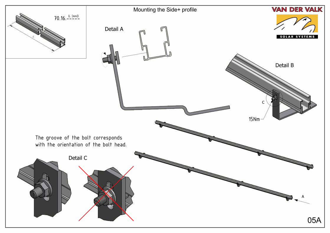
05A
Mounting the Side+ profile
The groove of the bolt correspondswith the orientation of the bolt head.
L
70.16.-----(L [mm])
Detail B
Detail C
C
A
Detail A
15Nm

D ( 1 : 1.5 )
E ( 1 : 2.5 )
G ( 1 : 2 )
A
B
C
D
E
G
05B
Mounting Side+ profile
Detail C
The groove of the bolt correspondswith the orientation of the bolt head.
Detail A
Detail B
A
C
72.11.00
Min. 1mm
At least 1 mm thread above the clamp.
12M 10M
2
1
3
When the bolt is tightened, the hangerbolt is forced intothe aluminium profile.
Top view
15Nm

AB
CDE F
06
Mounting the Side+ coupling
72.48.65
The groove of the bolt correspondswith the orientation of the bolt head.
A
Detail A
B
Detail B
15Nm
D ( 0,12 : 1 )
D
E
F
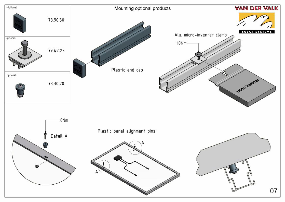
07
Mounting optional products
Optional:
73.30.20
73.90.50
77.42.23
Optional:
Optional:
Plastic end cap
Alu. micro-inventer clamp
Plastic panel alignment pins
ADetail A
A
10Nm
8Nm

D ( 1 : 5 )
B
C
D
08
Mounting panels
A
A
Detail A Detail A
72.15.52
Take the End Clamp out of it's slotto make the assembly easier.
The End Clamp can only be turned clockwise, so make sure that the End Clamp is placed the right way.
Detail A
Put the End Clamp in the right slotto continue the assembly.
1
2 3
4
5
8Nm

D ( 1 : 4 )
D
A
09
Mounting panels
72.15.50
1
23
5
4
4
A
A
A
A
A
Detail A
Detail A
See page 8
See page 8
8Nm

G ( 1 : 2.5 )
H ( 0,12 : 1 )
K ( 0,12 : 1 )
F
G
H
J
K
L
M
N
P
R
T
10
Mounting cable clamps
73.20.01Max. cable diameter Ø9 mm
Mounting cable clamp on Side+ profile.
Mounting cable clamp on panel.
Mounting cable clamp on Side+ profile.
73.20.05Max. cable diameter Ø9 mm
optional:

Van der Valk Solar Systems
Van der Valk Solar Systems is a specialist company that is fully
focused on developing and producing mounting systems for use with
solar panels. To this end we work in close collaboration with Van der
Valk Systemen, our sister company.
Van der Valk Systemen has been a well-known name in the field of
moving systems and stationary components for the greenhouse
horticultural sector and industry throughout the world since 1963. Van
der Valk Systemen’s high quality products have been individually
developed from a scientific approach and produced with mathematical
precision. They are made to be low-maintenance and to stand out
thanks to their durability, reliability, functionality and ease of assembly.
Both Van der Valk Systemen and Van der Valk Solar Systems only
introduce innovative products to the market. Our shared business
complex consists of 20,000 m2 of offices and production facilities, in
which modern machinery and the latest technologies facilitate develop-
ment, manufacturing and testing that is fast, flexible and precise.
Developer and producer of solar mounting systems for:
Open Fields Pitched Roofs Flat Roofs Greenhouses Water Features