Embed Size (px)
Citation preview
READ THESE INSTRUCTIONS CAREFULLY BEFORE INSTALLATION.KEEP THIS MANUAL IN A HANDY PLACE FOR FUTURE REFERENCE.
INSTALLATION MANUAL
BS unit
BS1Q10A7V1BBS1Q16A7V1BBS1Q25A7V1B
System air conditioner
EKBSVQLNP
(eg: ISOVER 1000S)
EKBSVQLNP
(eg: ISOVER 1000S)
A
1
2
3
4
5
6
7
8
9
10
Dai
kin
Eu
rop
e N
.V.
CE -
DECL
ARAT
ION-
OF-C
ONFO
RMIT
YCE
- KO
NFOR
MIT
ÄTSE
RKLÄ
RUNG
CE -
DECL
ARAT
ION-
DE-C
ONFO
RMIT
ECE
- CO
NFOR
MIT
EITS
VERK
LARI
NG
CE -
DECL
ARAC
ION-
DE-C
ONFO
RMID
ADCE
- DI
CHIA
RAZI
ONE-
DI-C
ONFO
RMIT
ACE
- ¢H
§ø™H
™YM
MOP
ºø™H
™
CE -
DECL
ARAÇ
ÃO-D
E-CO
NFOR
MID
ADE
СЕ -
ЗАЯВ
ЛЕНИ
Е-О
-СО
ОТВ
ЕТСТ
ВИИ
CE -
OPFY
LDEL
SESE
RKLÆ
RING
CE -
FÖRS
ÄKRA
N-OM
-ÖVE
RENS
TÄMM
ELSE
CE -
ERKL
ÆRI
NG O
M-S
AMSV
ARCE
- IL
MOI
TUS-
YHDE
NMUK
AISU
UDES
TACE
- PR
OHL
ÁŠEN
Í-O-S
HODĚ
CE -
IZJA
VA-O
-USK
LAĐE
NOST
ICE
- M
EGFE
LELŐ
SÉG
I-NYI
LATK
OZA
TCE
- DE
KLAR
ACJA
-ZG
ODN
OŚC
ICE
- DE
CLAR
AŢIE
-DE-
CONF
ORM
ITAT
E
CE -
IZJA
VA O
SKL
ADNO
STI
CE -
VAST
AVUS
DEKL
ARAT
SIO
ON
CE -
ДЕКЛ
АРАЦ
ИЯ-З
А-СЪ
ОТВЕ
ТСТВ
ИЕ
CE -
ATIT
IKTI
ES-D
EKLA
RACI
JACE
- AT
BILS
TĪBA
S-DE
KLAR
ĀCIJ
ACE
- VY
HLÁS
ENIE
-ZHO
DYCE
- UY
GUN
LUK-
BEYA
NI
01ar
e in
confo
rmity
with
the
follo
wing
sta
ndar
d(s)
or o
ther
nor
mat
ive d
ocum
ent(s
), pr
ovide
d th
at th
ese
are
used
in a
ccor
danc
e wi
th o
urins
tructi
ons:
02de
r/den
folge
nden
Nor
m(e
n) o
der e
inem
and
eren
Nor
mdo
kum
ent o
der -
doku
men
ten
entsp
richt
/ent
spre
chen
, unt
er d
er V
orau
sset
zung
,da
ß sie
gem
äß u
nser
en A
nweis
unge
n ein
gese
tzt w
erde
n:03
sont
confo
rmes
à la/
aux n
orm
e(s)
ou au
tre(s
) doc
umen
t(s) n
orm
atif(
s), p
our a
utan
t qu'i
ls so
ient u
tilisé
s con
form
émen
t à no
s ins
tructi
ons:
04co
nform
de vo
lgend
e nor
m(e
n) of
één o
f mee
r and
ere b
inden
de do
cum
ente
n zijn
, op v
oorw
aard
e dat
ze w
orde
n geb
ruikt
over
eenk
omsti
gon
ze in
struc
ties:
05es
tán
en co
nfor
mida
d co
n la(
s) si
guien
te(s
) nor
ma(
s) u
otro
(s) d
ocum
ento
(s) n
orm
ativo
(s),
siem
pre
que
sean
utili
zado
s de
acue
rdo
con
nues
tras i
nstru
ccion
es:
06so
no c
onfor
mi a
l(i) s
egue
nte(
i) sta
ndar
d(s)
o a
ltro(
i) do
cum
ento
(i) a
car
atte
re n
orm
ativo
, a p
atto
che
ven
gano
usa
ti in
conf
orm
ità a
lleno
stre
istru
zioni:
07›Ó
·È Û
‡Ìʈ
Ó· Ì
 ÙÔ
(·)
·ÎfiÏ
Ô˘ıÔ
(·)
ÚfiÙ
˘Ô(
·) ‹
¿ÏÏ
Ô ¤Á
ÁÚ·Ê
Ô(·)
ηÓ
ÔÓÈÛÌÒ
Ó, ˘
fi Ù
ËÓ
ÚÔ¸
fiıÂÛ
Ë fiÙ
È ¯ÚË
ÛÈÌÔ
ÔÈÔ‡Ó
Ù·È
Û‡ÌÊ
ˆÓ·
ÌÂ Ù
Ș Ô
‰ËÁ›Â˜
Ì·˜
:
08es
tão
em c
onfo
rmida
de c
om a
(s) s
eguin
te(s
) nor
ma(
s) o
u ou
tro(s
) doc
umen
to(s
) nor
mat
ivo(s
), de
sde
que
este
s se
jam u
tiliza
dos
deac
ordo
com
as n
ossa
s ins
truçõ
es:
09со
отве
тств
уют
след
ующи
м ст
анда
ртам
или
дру
гим
норм
атив
ным
доку
мент
ам, п
ри у
слов
ии и
х ис
поль
зова
ния
согл
асно
наш
имин
стру
кция
м:10
over
holde
r fø
lgend
e sta
ndar
d(er
) ell
er a
ndet
/and
re r
etnin
gsgiv
ende
dok
umen
t(er),
for
udsa
t at
diss
e an
vend
es i
henh
old t
il vo
reins
truks
er:
11re
spek
tive
utru
stning
är u
tförd
i öv
eren
sstä
mm
else
med
och
följe
r följ
ande
sta
ndar
d(er
) elle
r and
ra n
orm
givan
de d
okum
ent,
unde
rfö
rutsä
ttning
att
anvä
ndnin
g sk
er i ö
vere
nsstä
mm
else
med
våra
instr
uktio
ner:
12re
spek
tive
utsty
r er i
ove
rens
stem
mels
e m
ed fø
lgend
e sta
ndar
d(er
) elle
r and
re n
orm
given
de d
okum
ent(e
r), u
nder
foru
tsset
ning
av a
tdis
se b
ruke
s i h
enho
ld til
våre
instr
ukse
r:13
vasta
avat
seu
raav
ien s
tand
ardie
n ja
muid
en o
hjeell
isten
dok
umen
ttien
vaat
imuk
sia e
delly
ttäen
, et
tä n
iitä k
äyte
tään
ohje
idem
me
muk
aises
ti:14
za p
ředp
oklad
u, že
jsou
využ
ívány
v so
uladu
s na
šimi p
okyn
y, o
dpov
ídají
nás
ledují
cím n
orm
ám n
ebo
norm
ativn
ím d
okum
entů
m:
15u
sklad
u sa
slije
dećim
stan
dard
om(im
a) ili
dru
gim n
orm
ativn
im d
okum
ento
m(im
a), u
z uvje
t da
se o
ni ko
riste
u sk
ladu
s naš
im u
puta
ma:
16m
egfe
lelne
k az a
lábbi
szab
vány
(ok)
nak v
agy e
gyéb
irán
yadó
dok
umen
tum
(ok)
nak,
ha a
zoka
t előí
rás s
zerin
t has
ználj
ák:
17sp
ełniaj
ą wy
mog
i nas
tępu
jącyc
h no
rm i
innyc
h do
kum
entó
w no
rmali
zacy
jnych
, pod
war
unkie
m ż
e uż
ywan
e są
zgo
dnie
z na
szym
iins
trukc
jami:
18su
nt în
conf
orm
itate
cu u
rmăt
orul
(urm
ătoa
rele)
stan
dard
(e) s
au a
lt(e)
doc
umen
t(e) n
orm
ativ(
e), c
u co
ndiţia
ca a
ceste
a să
fie u
tiliza
te în
conf
orm
itate
cu in
struc
ţiunil
e no
astre
19sk
ladni
z nas
lednji
mi s
tand
ardi
in dr
ugim
i nor
mat
ivi, p
od p
ogoje
m, d
a se
upo
rablj
ajo v
sklad
u z n
ašim
i nav
odili:
20on
vasta
vuse
s jär
gmis(
t)e st
anda
rdi(t
e)ga
või te
iste
norm
atiiv
sete
dok
umen
tideg
a, ku
i neid
kasu
tata
kse
vasta
valt m
eie ju
hend
itele:
21съ
отве
тств
ат н
а сл
едни
те с
танд
арти
или
дру
ги н
орма
тивн
и до
куме
нти,
при
усл
овие
, че
се
изпо
лзва
т съ
глас
но н
ашит
еин
стру
кции
:22
atitin
ka že
miau
nur
odytu
s sta
ndar
tus i
r (ar
ba) k
itus n
orm
inius
dok
umen
tus s
u są
lyga,
kad
yra
naud
ojam
i pag
al m
ūsų
nuro
dym
us:
23ta
d, ja
lieto
ti atb
ilsto
ši ra
žotā
ja no
rādī
jumiem
, atb
ilst s
ekojo
šiem
stan
darti
em u
n cit
iem n
orm
atīvi
em d
okum
entie
m:
24sú
v zh
ode
s nas
ledov
nou(
ými)
norm
ou(a
mi)
alebo
iným
(i) n
orm
atívn
ym(i)
dok
umen
tom
(am
i), za
pre
dpok
ladu,
že sa
pou
žívajú
v sú
lade
s naš
im n
ávod
om:
25ür
ünün
, tali
mat
larım
ıza g
öre
kulla
nılm
ası k
oşulu
yla a
şağı
daki
stand
artla
r ve
norm
beli
rten
belge
lerle
uyum
ludur
:
01Di
recti
ves,
as a
men
ded.
02Di
rekti
ven,
gem
äß Ä
nder
ung.
03Di
recti
ves,
telle
s que
mod
ifiées
.04
Rich
tlijne
n, zo
als g
eam
ende
erd.
05Di
recti
vas,
segú
n lo
enm
enda
do.
06Di
rettiv
e, co
me
da m
odific
a.07
√‰Ë
ÁÈÒv
, fiˆ
˜ ¤¯
Ô˘Ó
ÙÚÔ
ÔÔÈËı
›.08
Dire
ctiva
s, co
nform
e alt
eraç
ão e
m.
09Ди
рект
ив со
все
ми п
опра
вкам
и.
10Di
rekti
ver,
med
sene
re æ
ndrin
ger.
11Di
rekti
v, m
ed fö
reta
gna
ändr
ingar
.12
Dire
ktive
r, m
ed fo
reta
tte e
ndrin
ger.
13Di
rektiiv
ejä, s
ellais
ina ku
in ne
ovat
muute
ttuina
.14
v plat
ném
zněn
í.15
Smjer
nice,
kako
je iz
mije
njeno
.16
irány
elv(e
k) és
mód
osítá
saik
rend
elkez
éseit
.17
z póź
niejsz
ymi p
opra
wkam
i.18
Dire
ctive
lor, c
u am
enda
men
tele
resp
ectiv
e.
19Di
rekti
ve z
vsem
i spr
emem
bam
i.20
Dire
ktiivi
d ko
os m
uuda
tuste
ga.
21Ди
рект
иви,
с те
хнит
е из
мене
ния.
22Di
rekty
vose
su p
apild
ymais
.23
Dire
ktīvā
s un
to p
apild
inājum
os.
24Sm
ernic
e, v
platn
om zn
ení.
25De
ğiştir
ilmiş
halle
riyle
Yöne
tmeli
kler.
01fol
lowing
the
prov
ision
s of:
02ge
mäß
den
Vor
schr
iften
der:
03co
nform
émen
t aux
stipu
lation
s des
:04
over
eenk
omsti
g de
bep
aling
en va
n:05
siguie
ndo
las d
ispos
icion
es d
e:06
seco
ndo
le pr
escr
izion
i per
:07
ÌÂ Ù
‹ÚËÛ
Ë Ùˆ
v ‰È·Ù
¿Íˆ
v Ùˆ
v:08
de a
cord
o co
m o
pre
visto
em
:09
в со
отве
тств
ии с
поло
жени
ями:
10un
der i
agtta
gelse
af b
este
mm
elser
ne i:
11en
ligt v
illkor
en i:
12git
t i he
nhold
til b
este
mm
elsen
e i:
13no
udat
taen
mää
räyk
siä:
14za
dod
ržen
í usta
nove
ní p
ředp
isu:
15pr
ema
odre
dbam
a:16
köve
ti a(z
):17
zgod
nie z
posta
nowi
eniam
i Dyr
ektyw
:18
în u
rma
prev
eder
ilor:
19ob
upo
števa
nju d
oločb
:20
vasta
valt n
õuet
ele:
21сл
едва
йки
клау
зите
на:
22lai
kant
is nu
osta
tų, p
ateik
iamų:
23iev
ērojo
t pra
sības
, kas
not
eikta
s:24
održ
iavajú
c usta
nove
nia:
25bu
nun
koşu
lların
a uy
gun
olara
k:
01
Note
*as
set o
ut in
<A> a
nd ju
dged
posit
ively
by <B
> ac
cordi
ng to
the
Certi
ficate
<C>.
02
Hinw
eis *
wie i
n der
<A> a
ufgefü
hrt u
nd vo
n <B>
posit
iv be
urtei
lt gem
äß Ze
rtifik
at <C
>.03
Re
marq
ue *
tel qu
e défi
ni da
ns <A
> et é
valué
posit
iveme
nt pa
r <B
> con
formé
ment
au C
ertifi
cat <
C>.
04
Beme
rk *
zoals
verm
eld in
<A> e
n pos
itief b
eoord
eeld
door
<B> o
veree
nkom
stig C
ertifi
caat
<C>.
05
Nota
*co
mo se
estab
lece e
n <A>
y es
valor
ado
posit
ivame
nte po
r <B>
de ac
uerdo
con e
l Ce
rtific
ado <
C>.
06
Nota
*de
linea
to ne
l <A>
e giu
dicato
posit
ivame
nte
da <B
> sec
ondo
il Ce
rtific
ato <C
>.07
™Ë
Ì›ˆ
ÛË *
fiˆ˜
ηı
ÔÚ›˙Â
Ù·È Û
ÙÔ <
A> Î
·È ÎÚ
›ÓÂÙ·
È ıÂÙ
Èο
·fi
ÙÔ <
B> Û
‡Ìʈ
Ó· Ì
 ÙÔ
¶ÈÛÙ
ÔÔÈË
ÙÈÎfi
<C>.
08
Nota
*tal
como
estab
elecid
o em
<A> e
com
o pare
cer
posit
ivo de
<B> d
e aco
rdo co
m o C
ertifi
cado
<C>.
09
Прим
ечан
ие *
как у
каза
но в
<A>
и в со
отве
тств
ии с
поло
жите
льны
м ре
шени
ем <
B> со
глас
но
Свид
етел
ьств
у <C>
.10
Be
mærk
*so
m an
ført i
<A> o
g pos
itivt v
urdere
t af <
B> i
henh
old til
Cer
tifika
t <C>
.
11
Infor
matio
n *en
ligt <
A> oc
h god
känts
av <B
> enli
gt Ce
rtifik
atet <
C>.
12
Merk
*so
m de
t frem
komm
er i <
A> og
gjen
nom
posit
iv be
dømm
else a
v <B>
ifølge
Ser
tifika
t <C>
.13
Hu
om *
jotka
on es
itetty
asiak
irjass
a <A>
ja jo
tka <B
> on
hyvä
ksyn
yt Se
rtifik
aatin
<C> m
ukais
esti.
14
Pozn
ámka
*jak
bylo
uved
eno v
<A> a
pozit
ivně z
jištěn
o <B>
v so
uladu
s os
vědč
ením
<C>.
15
Napo
mena
*ka
ko je
izlož
eno u
<A> i
pozit
ivno o
cijen
jeno o
d str
ane <
B> pr
ema C
ertif
ikatu
<C>.
16
Megje
gyzé
s *a(
z) <A
> alap
ján, a
(z) <B
> iga
zolta
a me
gfelel
ést,
a(z)
<C> t
anús
ítván
y sze
rint.
17
Uwag
a *zg
odnie
z do
kume
ntacją
<A>,
pozy
tywną
opini
ą <B
> i Ś
wiad
ectw
em <C
>.18
No
tă *
aşa c
um es
te sta
bilit î
n <A>
şi ap
recia
t poz
itiv
de <B
> în c
onfor
mitat
e cu C
ertif
icatu
l <C>
.19
Op
omba
*ko
t je do
ločen
o v <A
> in o
dobr
eno s
stra
ni <B
> v
sklad
u s ce
rtifik
atom
<C>.
20
Märk
us *
nagu
on nä
idatud
doku
mend
is <A
> ja h
eaks
kii
detud
<B> j
ärgi
vasta
valt s
ertif
ikaad
ile <C
>.
21
Забе
лежк
а *ка
кто е
изло
жено
в <A
> и о
цене
но
поло
жите
лно о
т <B>
съгл
асно
Cе
ртиф
икат
а <C>
.22
Pa
staba
*ka
ip nu
statyt
a <A>
ir ka
ip tei
giama
i nus
pręs
ta <B
> pa
gal S
ertif
ikatą
<C>.
23
Piez
īmes
*kā
norā
dīts <
A> un
atbil
stoši
<B> p
ozitīv
ajam
vērtē
jumam
sask
aņā a
r ser
tifikā
tu <C
>.24
Po
znám
ka *
ako b
olo uv
eden
é v <A
> a po
zitívn
e zist
ené <
B> v
súlad
e s o
sved
čením
<C>.
25
Not *
<A>‘d
a be
lirtild
iği g
ibi v
e <C
> Se
rtifik
asın
agö
re
<B>
tara
fında
n olu
mlu
olara
kde
ğerle
ndiril
diği g
ibi.
<A>
DA
IKIN
.TC
F.03
0A10
/01-
2014
<B>
TÜ
V (
NB
1856
)
<C>
1208
0901
.T30
EN
6033
5-2-
40,
3PW40917-4E
Jean
-Pie
rre
Beu
selin
ckD
irect
orO
sten
d, 5
th o
f May
201
4
Low
Vol
tage
200
6/95
/EC
Ele
ctro
mag
netic
Com
patib
ility
200
4/10
8/E
C*
BS
1Q10
A7V
1B*,
BS
1Q16
A7V
1B*,
BS
1Q25
A7V
1B*,
* =
, ,
1, 2
, 3, .
.., 9
01 a
dec
lares
unde
r its s
ole re
spon
sibilit
y tha
t the a
ir con
dition
ing eq
uipme
nt to
which
this
decla
ration
relat
es:
02 d
erkl
ärt a
uf se
ine al
leinig
e Vera
ntwor
tung d
ass d
ie Au
srüstu
ng de
r Klim
agerä
te für
die d
iese E
rklär
ung b
estim
mt is
t:03
f d
éclar
e sou
s sa s
eule
respo
nsab
ilité q
ue l'é
quipe
ment
d'air c
ondit
ionné
visé
s par
la pré
sente
décla
ration
:04
l ve
rklaa
rt hie
rbij o
p eige
n exc
lusiev
e vera
ntwoo
rdelijk
heid
dat d
e airc
ondit
ioning
appa
ratuu
r waa
rop de
ze ve
rklar
ing be
trekk
ing he
eft:
05 e
dec
lara b
ajo su
única
resp
onsa
bilida
d que
el eq
uipo d
e aire
acon
dicion
ado a
l que
hace
refer
encia
la de
clarac
ión:
06 i
dich
iara s
otto l
a prop
ria re
spon
sabil
ità ch
e gli a
ppare
cchi
di co
ndizi
onam
ento
a cui
è rife
rita qu
esta
dichia
razion
e:07
g ‰
ËÏÒÓ
ÂÈ ÌÂ
·Ô
ÎÏÂÈÛ
ÙÈ΋
Ù˘
¢ı‡
ÓË fi
ÙÈ Ô
ÂÍÔ
ÏÈÛÌfi
˜ Ùˆ
Ó ÎÏ
ÈÌ·ÙÈÛ
ÙÈÎÒÓ
Û˘Û
΢Ò
Ó ÛÙ
· Ô
Ô›· ·
ӷʤ
ÚÂÙ·
È Ë
·ÚÔ‡
Û· ‰
‹ÏˆÛ
Ë:08
p d
eclar
a sob
sua e
xclus
iva re
spon
sabil
idade
que o
s equ
ipame
ntos d
e ar c
ondic
ionad
o a qu
e esta
decla
ração
se re
fere:
09 u
заяв
ляет,
искл
ючит
ельн
о под
свою
отве
тстве
ннос
ть, чт
о обо
рудов
ание
для к
онди
цион
иров
ания
возд
уха, к
кото
рому
отно
сится
насто
ящее
заяв
лени
е:10
q e
rklær
er un
der e
nean
svar,
at ud
styret
til kl
imare
guler
ing, s
om de
nne d
eklar
ation
vedrø
rer:
11 s
dek
larere
r i eg
ensk
ap av
huvu
dans
varig
, att l
uftko
nditio
nerin
gsutr
ustni
ngen
som
berör
s av d
enna
dekla
ration
inne
bär a
tt:12
n e
rklær
er et
fullst
endig
ansv
ar for
at de
t luftk
ondis
joner
ingsu
tstyr
som
berø
res av
denn
e dek
laras
jon, in
nebæ
rer at
:13
j ilm
oittaa
yksin
omaa
n oma
lla va
stuull
aan,
että t
ämän
ilmoit
ukse
n tar
koitta
mat il
masto
intila
itteet:
14 c
pro
hlašu
je ve
své p
lné od
pově
dnos
ti, že
klim
atiza
ční z
aříze
ní, k
nimž s
e toto
proh
lášen
í vzta
huje:
15 y
izjav
ljuje
pod i
sklju
čivo v
lastito
m od
govo
rnoš
ću da
opre
ma za
klim
atiza
ciju n
a koju
se ov
a izja
va od
nosi:
16 h
telje
s fele
lőssé
ge tu
datáb
an ki
jelen
ti, ho
gy a
klíma
bere
ndez
ések
, mely
ekre
e ny
ilatko
zat v
onatk
ozik:
17 m
dek
laruje
na w
łasną
i wyłą
czną
odpo
wied
zialno
ść, ż
e klim
atyza
tory,
któryc
h doty
czy n
iniejs
za de
klara
cja:
18 r
dec
lară p
e pro
prie
răsp
unde
re că
echip
amen
tele d
e aer
cond
iţiona
t la ca
re se
refer
ă ace
astă
decla
raţie
:19
o z
vso o
dgov
orno
stjo i
zjavlj
a, da
je op
rema
klim
atskih
napr
av, n
a kate
ro se
izjav
a nan
aša:
20 x
kinn
itab o
ma tä
ieliku
l vas
tutus
el, et
käes
oleva
dekla
ratsi
ooni
alla k
uuluv
kliim
asea
dmete
varu
stus:
21 b
дек
лари
ра на
своя
отго
ворн
ост,
че об
оруд
ване
то за
клим
атич
на ин
стал
ация
, за к
оето
се от
нася
тази
дек
лара
ция:
22 t
visi
ška s
avo a
tsako
mybe
skelb
ia, ka
d oro
kond
icion
avim
o įra
nga,
kuria
i taiko
ma ši
dekla
racij
a:23
v a
r piln
u atbi
ldību
aplie
cina,
ka tā
lāk uz
skait
ītās g
aisa k
ondic
ionēš
anas
iekā
rtas,
uz ku
riem
attiec
as šī
dekla
rācij
a:24
k v
yhlas
uje na
vlas
tnú zo
dpov
edno
sť, že
klim
atiza
čné z
ariad
enie,
na kt
oré s
a vzťa
huje
toto v
yhlás
enie:
25
w ta
mam
en ke
ndi s
orum
luluğ
unda
olm
ak ü
zere
bu
bildir
inin
ilgili
olduğ
u kli
ma
dona
nım
ının
aşa
ğıda
ki gib
i oldu
ğunu
bey
an e
der:
BS1Q10A7V1BBS1Q16A7V1BBS1Q25A7V1B
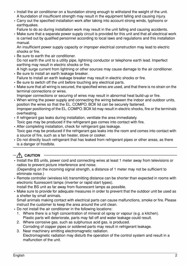
VRVIV SYSTEM Air Conditioners Installation manual
CONTENTS1. SAFETY PRECAUTIONS ..............................................................................................1
2. BEFORE INSTALLATION..............................................................................................4
3. SELECTING INSTALLATION SITE ...............................................................................5
4. PREPARATIONS BEFORE INSTALLATION.................................................................6
5. BS UNIT INSTALLATION...............................................................................................7
6. REFRIGERANT PIPING WORK ....................................................................................8
7. ELECTRIC WIRING WORK.........................................................................................13
8. INITIAL SETTING.........................................................................................................16
9. TEST OPERATION......................................................................................................16
10. WIRING PARTS TABLE...............................................................................................17
1. SAFETY PRECAUTIONSPlease read these “SAFETY PRECAUTIONS” carefully before installing air conditioning unit and be sure to install it correctly. After completing installation, conduct a trial operation to check for faults and explain to the customer how to operate the air conditioner and take care of it with the aid of the operation manual. Ask the customer to store the installation manual along with the operation manual for future reference.This air conditioner comes under the term “appliances not accessible to the general public”.
VRV System is a class A product. In a domestic environment this product may cause radio interference in which case the user may be required to take adequate measures.
The original instructions are written in English. All other languages are translations of the original instructions.
Meaning of WARNING and CAUTION notices
WARNING ........Failure to follow these instructions properly may result in personal injury or loss of life.
CAUTION ..........Failure to observe these instructions properly may result in property damage or
personal injury, which may be serious depending on the circumstances.
WARNING• Ask your dealer or qualified personnel to carry out installation work.
Do not attempt to install the air conditioner yourself. Improper installation may result in water leakage, electric shocks or fire.
• Install the air conditioner in accordance with the instructions in this installation manual.Improper installation may result in water leakage, electric shocks or fire.
• When installing the unit in a small room, take measures against to keep refrigerant concentration from exceeding allowable safety limits in the event of refrigerant leakage.Contact the place of purchase for more information. Excessive refrigerant in a closed ambient can lead to oxygen deficiency.
• Be sure to use only the specified accessories and parts for installation work.Failure to use the specified parts may result in the unit falling, water leakage, electric shocks or fire.
1 English
• Install the air conditioner on a foundation strong enough to withstand the weight of the unit.A foundation of insufficient strength may result in the equipment falling and causing injury.
• Carry out the specified installation work after taking into account strong winds, typhoons or earthquakes.Failure to do so during installation work may result in the unit falling and causing accidents.
• Make sure that a separate power supply circuit is provided for this unit and that all electrical work is carried out by qualified personnel according to local laws and regulations and this installation manual.An insufficient power supply capacity or improper electrical construction may lead to electric shocks or fire.
• Be sure to earth the air conditioner.Do not earth the unit to a utility pipe, lightning conductor or telephone earth lead. Imperfect earthing may result in electric shocks or fire.A high surge current from lightning or other sources may cause damage to the air conditioner.
• Be sure to install an earth leakage breaker.Failure to install an earth leakage breaker may result in electric shocks or fire.
• Be sure to switch off the unit before touching any electrical parts.• Make sure that all wiring is secured, the specified wires are used, and that there is no strain on the
terminal connections or wires.Improper connections or securing of wires may result in abnormal heat build-up or fire.
• When wiring the power supply and connecting the wiring between the indoor and outdoor units, position the wires so that the EL. COMPO. BOX lid can be securely fastened.Improper positioning of the EL. COMPO. BOX lid may result in electric shocks, fire or the terminals overheating.
• If refrigerant gas leaks during installation, ventilate the area immediately.Toxic gas may be produced if the refrigerant gas comes into contact with fire.
• After completing installation, check for refrigerant gas leakage.Toxic gas may be produced if the refrigerant gas leaks into the room and comes into contact with a source of fire, such as a fan heater, stove or cooker.
• Do not directly touch refrigerant that has leaked from refrigerant pipes or other areas, as there is a danger of frostbite.
CAUTION• Install the BS units, power cord and connecting wires at least 1 meter away from televisions or
radios to prevent picture interference and noise. (Depending on the incoming signal strength, a distance of 1 meter may not be sufficient to eliminate noise.)
• Remote controller (wireless kit) transmitting distance can be shorter than expected in rooms with electronic fluorescent lamps (inverter or rapid start types). Install the BS unit as far away from fluorescent lamps as possible.
• Make sure to provide for adequate measures in order to prevent that the outdoor unit be used as a shelter by small animals. Small animals making contact with electrical parts can cause malfunctions, smoke or fire. Please instruct the customer to keep the area around the unit clean.
• Do not install the air conditioner in the following locations:1. Where there is a high concentration of mineral oil spray or vapour (e.g. a kitchen).
Plastic parts will deteriorate, parts may fall off and water leakage could result.2. Where corrosive gas, such as sulphurous acid gas, is produced.
Corroding of copper pipes or soldered parts may result in refrigerant leakage.3. Near machinery emitting electromagnetic radiation.
Electromagnetic radiation may disturb the operation of the control system and result in a malfunction of the unit.
English 2
4. Where flammable gas may leak, where there is carbon fibre or ignitable dust suspensions in the air, or where volatile flammables such as paint thinner or gasoline are handled. Operating the unit in such conditions may result in fire.
5. Do not use in areas where the air is salty, such as along seacoasts, in factories or other areas with significant voltage fluctuations, or in automobiles and watercraft.Doing so could result in a malfunction.
CAUTIONThe refrigerant R410A requires that strict precautions be observed for keeping the system clean, dry and tightly sealed.Clean and dryStrict measures must be taken to keep impurities (including SUNISO oil and other mineral oils as well as moisture) out of the system.Tightly sealedR410A contains no chlorine, does not destroy the ozone layer and so does not reduce the earth’s protection against harmful ultraviolet radiation. R410A will contribute only slightly to the greenhouse effect if released into the atmosphere. Therefore, sealing tightness is particularly important in installation.Carefully read the chapter “REFRIGERANT PIPING WORK” and strictly observe the correct procedures.
3 English
2. BEFORE INSTALLATION
2-1 CAUTION CONCERNING NEW REFRIGERANT SERIES• Since design pressure is 4.0 MPa or 40 bar (for R407C units: 3.3 MPa or 33 bar), the thickness of pipes
must be greater than previously. Since R410A is a mixed refrigerant, the required additional refrigerant must be charged in its liquid state. (If the system is charged with refrigerant in its gaseous state, due to composition change, the system will not function normally.)The indoor/outdoor unit is designed for R410A. See the catalogue for indoor/outdoor unit models that can be connected. (Normal operation is not possible when connecting units that are originally designed for other refrigerants.
2-2 PRECAUTIONS• Hold the unit by the Hanging brackets (4 points) when opening the box and moving it, and do not lift it
holding on to any other part especially the refrigerant piping.• About installation of outdoor and indoor unit, refer to the installation manual provided with the outdoor and
the indoor unit.• This unit, both indoor and outdoor, is suitable for installation in a commercial and light industrial environment.
If installed as a household appliance it could cause electromagnetic interference.
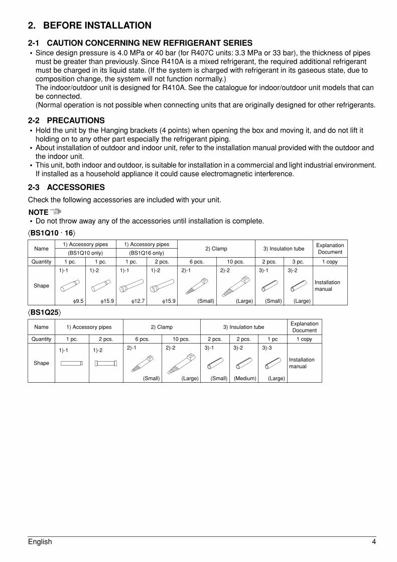
2-3 ACCESSORIES
Check the following accessories are included with your unit.
NOTE• Do not throw away any of the accessories until installation is complete.
⟨BS1Q10 · 16⟩
⟨BS1Q25⟩
Name1) Accessory pipes 1) Accessory pipes
2) Clamp 3) Insulation tubeExplanation Document(BS1Q10 only) (BS1Q16 only)
Quantity 1 pc. 1 pc. 1 pc. 2 pcs. 6 pcs. 10 pcs. 2 pcs. 3 pc. 1 copy
Shape
1)-1
φ9.5
1)-2
φ15.9
1)-1
φ12.7
1)-2
φ15.9
2)-1
(Small)
2)-2
(Large)
3)-1
(Small)
3)-2
(Large)
Installation manual
Name 1) Accessory pipes 2) Clamp 3) Insulation tubeExplanation Document
Quantity 1 pc. 2 pcs. 6 pcs. 10 pcs. 2 pcs. 2 pcs. 1 pc 1 copy
Shape
1)-1 1)-2 2)-1
(Small)
2)-2
(Large)
3)-1
(Small)
3)-2
(Medium)
3)-3
(Large)
Installation manual
English 4
2-4 COMBINATION• This BS unit is only for systems for Models REYQ-T.
It cannot be connected to systems for Models REYQ-M+REYQ-P.• For series of applicable indoor units, refer to the catalog or other literature.• Select the BS unit to fit the total capacity (sum of unit’s capacity) and max. number of the indoor units to be
connected downstream. About indoor unit’s capacity, refer to the Table 2.
Table 1
Table 2
* About indoor unit’s capacity for HRV type (VKM), refer to the Engineering data book.
<Example>In case of the BS unit witch connect two FXCQ32M and two FXSQ40M.
Total capacity = 31.25x2+40x2 = 142.5 → Select BS1Q16
2-5 CHECK ITEM• For the following items, take special care during construction and check after installation is finished.
Completion check items
Hand-over check items
3. SELECTING INSTALLATION SITE
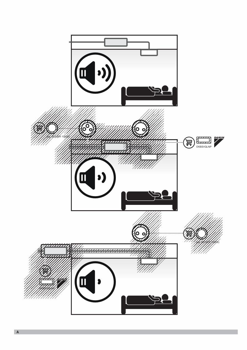
The equipment is not intended to be installed in spaces where it is better to avoid noise, like bedrooms. (Refer to Fig. A).The equipment is not intended for use in a potentially explosive atmosphere.Select an installation site where the following conditions are satisfied and that meets with your customer’s approval.• Where is resistible against weight of BS unit.• Locations where the wall is not significantly tilted.• Where sufficient clearance for maintenance and service can be ensured. (Refer to Fig. 1)• Locations where an inspection hole (Refer to Fig. 2) can be installed to EL. COMPO. BOX side (See Note).• Where the total piping length involving indoor unit and outdoor unit is below the allowable piping length.
(See installation manual attached to outdoor unit.)
Model Total capacity of all downstream indoor units Max. number of all downstream indoor units
BS1Q10 A ≤ 100 6
BS1Q16 100 < A ≤ 160 8
BS1Q25 160 < A ≤ 250 8
Capacity expressed as indoor unit’s model No. 15 20 25 32 40 50 63 80 100 125 200 250
Indoor unit’s capacity (for use in computation) 15 20 25 31.25 40 50 62.5 80 100 125 200 250
Check items Problems Check
Are the BS units installed securely? Falling, vibration, and operating noise
Have you performed a gas leak test? Does not cool or heat
Is the insulation complete? (Refrigerant piping and pipe connection part) Water leaking
Is the voltage the same as that listed on the unit’s nameplate? Does not operate/burnt out
Are all the wiring and piping correct? Does not operate/burnt out
Is the unit grounded? Dangers during electrical leak
Is the thickness of the power cord as specified? Does not operate/burnt out
Check items Check
Did you close the EL. COMPO. BOX lid?
Did you hand the operating manual and warranty card to the customer?
5 English
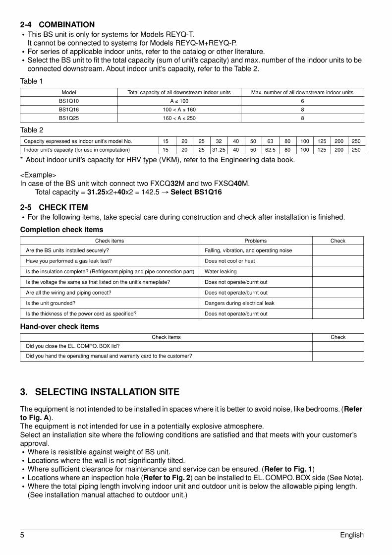
Note: The EL. COMPO. BOX mounting surface can be changed.For information on how to change the mounting surface, refer to “5. BS UNIT INSTALLATION”.
NOTES• Study if the installation location is strong enough to hold the weight of the unit, and if necessary reinforce
the area with a beam or other member and then install suspension bolts. Use the suspension bolts to install the unit. (Refer to “4. PREPARATIONS BEFORE INSTALLATION”)
• Install the BS unit and its power supply wiring and transmission wiring at least 1 meter away from televisions and radios to prevent image distortion and noise in those devices. Noise may still be introduced at this distance depending on the electromagnetic wave conditions.
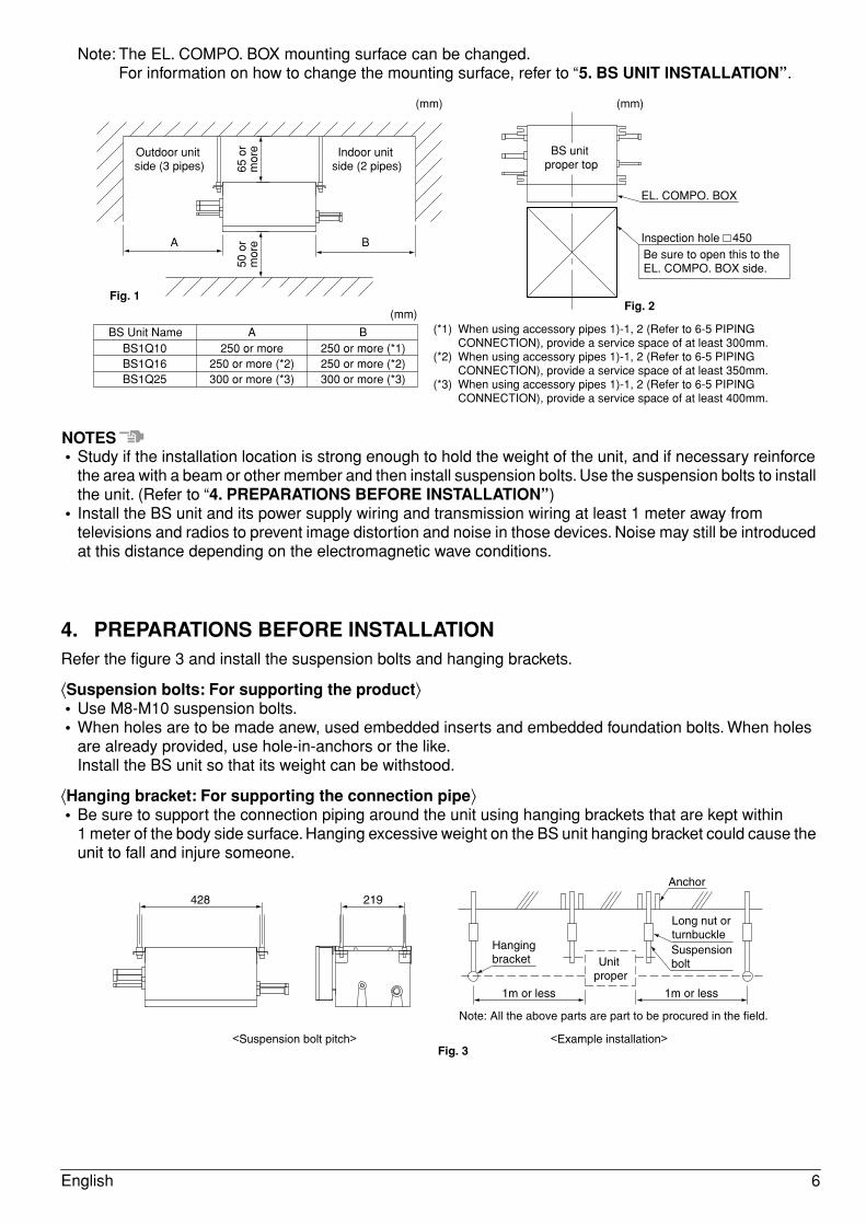
4. PREPARATIONS BEFORE INSTALLATIONRefer the figure 3 and install the suspension bolts and hanging brackets.
⟨Suspension bolts: For supporting the product⟩• Use M8-M10 suspension bolts.• When holes are to be made anew, used embedded inserts and embedded foundation bolts. When holes
are already provided, use hole-in-anchors or the like.Install the BS unit so that its weight can be withstood.
⟨Hanging bracket: For supporting the connection pipe⟩• Be sure to support the connection piping around the unit using hanging brackets that are kept within
1 meter of the body side surface. Hanging excessive weight on the BS unit hanging bracket could cause the unit to fall and injure someone.
(mm)
BS Unit NameBS1Q10BS1Q16BS1Q25
250 or more250 or more (*2)300 or more (*3)
250 or more (*1)250 or more (*2)300 or more (*3)
A B (*1) When using accessory pipes 1)-1, 2 (Refer to 6-5 PIPING CONNECTION), provide a service space of at least 300mm.
(*2) When using accessory pipes 1)-1, 2 (Refer to 6-5 PIPING CONNECTION), provide a service space of at least 350mm.
(*3) When using accessory pipes 1)-1, 2 (Refer to 6-5 PIPING CONNECTION), provide a service space of at least 400mm.
A B
Indoor unit side (2 pipes)
(mm)
Outdoor unit side (3 pipes) 65
or
mor
e50
or
mor
e
BS unit proper top
EL. COMPO. BOX
Inspection hole 450
(mm)
Be sure to open this to the EL. COMPO. BOX side.
Fig. 1Fig. 2
428 219
Hanging bracket
Suspension bolt
Long nut orturnbuckle
Anchor
1m or less 1m or less
Unit proper
<Suspension bolt pitch> <Example installation>
Note: All the above parts are part to be procured in the field.
Fig. 3
English 6
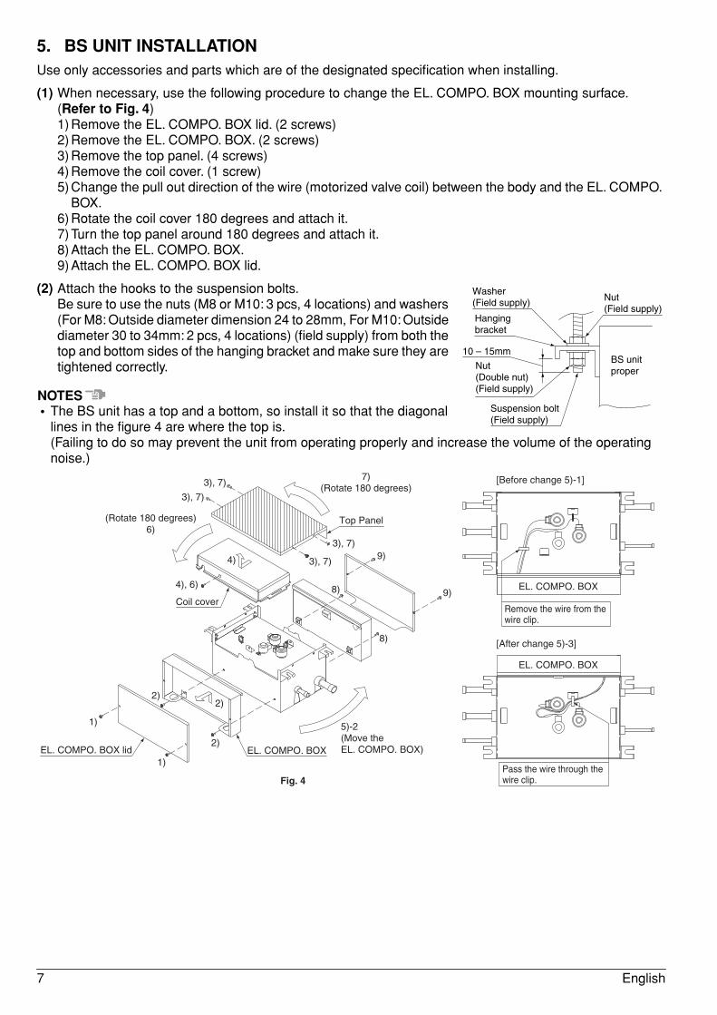
5. BS UNIT INSTALLATIONUse only accessories and parts which are of the designated specification when installing.
(1) When necessary, use the following procedure to change the EL. COMPO. BOX mounting surface. (Refer to Fig. 4)1) Remove the EL. COMPO. BOX lid. (2 screws)2) Remove the EL. COMPO. BOX. (2 screws)3) Remove the top panel. (4 screws)4) Remove the coil cover. (1 screw)5) Change the pull out direction of the wire (motorized valve coil) between the body and the EL. COMPO.
BOX.6) Rotate the coil cover 180 degrees and attach it.7) Turn the top panel around 180 degrees and attach it.8) Attach the EL. COMPO. BOX.9) Attach the EL. COMPO. BOX lid.
(2) Attach the hooks to the suspension bolts.Be sure to use the nuts (M8 or M10: 3 pcs, 4 locations) and washers (For M8: Outside diameter dimension 24 to 28mm, For M10: Outside diameter 30 to 34mm: 2 pcs, 4 locations) (field supply) from both the top and bottom sides of the hanging bracket and make sure they are tightened correctly.
NOTES• The BS unit has a top and a bottom, so install it so that the diagonal
lines in the figure 4 are where the top is.(Failing to do so may prevent the unit from operating properly and increase the volume of the operating noise.)
Washer (Field supply) Nut
(Field supply)
BS unit proper
Hanging bracket
10 – 15mm
Nut(Double nut)(Field supply)
Suspension bolt(Field supply)
EL. COMPO. BOX lid
Coil cover
Top Panel
EL. COMPO. BOX
5)-2(Move the EL. COMPO. BOX)
1)
1)
2)
4), 6)
3), 7)
3), 7)
3), 7)
3), 7)
(Rotate 180 degrees) 6)
7)(Rotate 180 degrees)
2)
9)
9)
8)
8)
4)
2)
[Before change 5)-1]
[After change 5)-3]
EL. COMPO. BOX
EL. COMPO. BOX
Remove the wire from the wire clip.
Pass the wire through the wire clip.Fig. 4
7 English
6. REFRIGERANT PIPING WORK• For instruction for installing piping between the outdoor unit and BS unit, selecting a refrigerant branch kit,
and installing piping between the refrigerant branch kit and the indoor unit, refer to the installation manual and equipment design materials included with the outdoor unit.
• Before beginning the work, always check to make sure the type of refrigerant used is R410A. (The unit will not operate correctly with a different type of refrigerant.)
• Insulate all of the piping including the liquid pipes, HP/LP gas pipes, suction gas pipes, gas pipes, equalizer pipes (piping between outdoor units when an outdoor multi-unit system), and the pipe connections for these. Not insulting these pipes could result in water leaks or burns. In particular, suction gas flows in the HP/LP gas piping during full cooling operation, so the same amount of insulation as used for the suction gas piping is required. In addition, high-pressure gas flows in the HP/LP gas piping and gas piping, so use insulation that can withstand more than 120˚C.
• Reinforce the insulation material when necessary for the installation environment. Refer to the following as a guideline.• For 30˚C, RH75% to 80%: Thickness at least 15mm• For 30˚C, over RH80%: Thickness at least 20mmIf not reinforced, condensation could form on the surface of the insulation. For details, refer to the Engineering data book.
NOTES• This product only uses the new refrigerant (R410A). Be sure to use the special pipe cutters for R410A,
during installation.• Make sure that nothing besides the specified refrigerant, such as air, gets into the refrigerant piping.• If refrigerant gas leaks during the work, ventilate the area. (The outdoor units are filled with refrigerant.)
6-1 PIPING MATERIAL SELECTION• Use only pipes which are clean inside and outside and which do not accumulate harmful sulfur, oxidants,
dirt, cutting oils, moisture, or other contamination. (Foreign materials inside pipes including oils for fabrication must be 30mg/10m or less.)
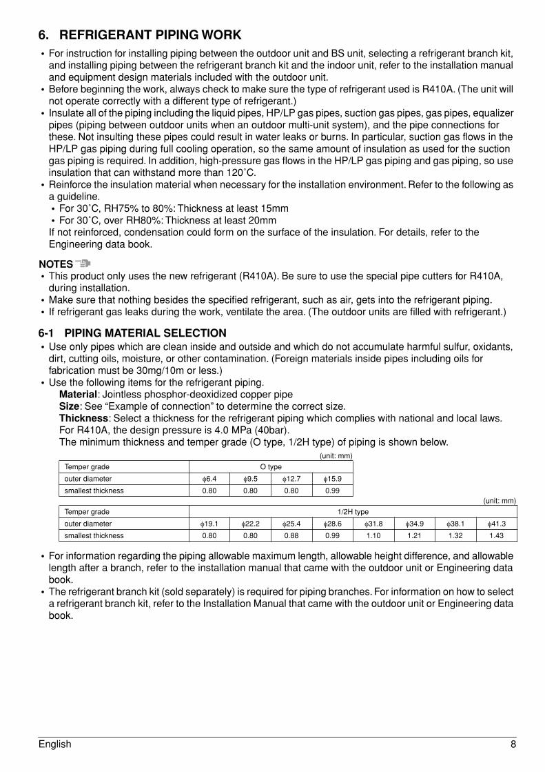
• Use the following items for the refrigerant piping.Material: Jointless phosphor-deoxidized copper pipeSize: See “Example of connection” to determine the correct size.Thickness: Select a thickness for the refrigerant piping which complies with national and local laws.For R410A, the design pressure is 4.0 MPa (40bar).The minimum thickness and temper grade (O type, 1/2H type) of piping is shown below.
(unit: mm)
(unit: mm)
• For information regarding the piping allowable maximum length, allowable height difference, and allowable length after a branch, refer to the installation manual that came with the outdoor unit or Engineering data book.
• The refrigerant branch kit (sold separately) is required for piping branches. For information on how to select a refrigerant branch kit, refer to the Installation Manual that came with the outdoor unit or Engineering data book.
Temper grade O type
outer diameter φ6.4 φ9.5 φ12.7 φ15.9
smallest thickness 0.80 0.80 0.80 0.99
Temper grade 1/2H type
outer diameter φ19.1 φ22.2 φ25.4 φ28.6 φ31.8 φ34.9 φ38.1 φ41.3
smallest thickness 0.80 0.80 0.88 0.99 1.10 1.21 1.32 1.43
English 8
6-2 PROTECTION AGAINST CONTAMINATION WHEN INSTALLING PIPESProtect the piping to prevent moisture, dirt, dust, etc. from entering the piping.
NOTEExercise special caution to prevent dirt or dust when passing piping through holes in walls and when passing pipe edges to the exterior.
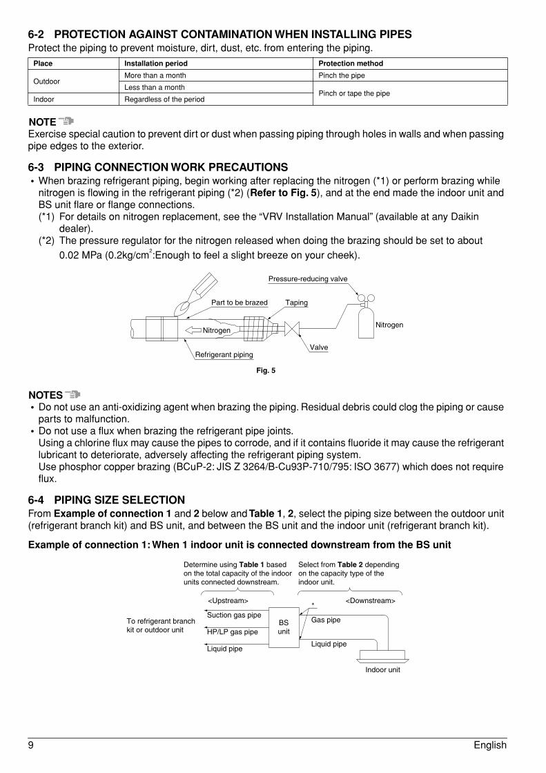
6-3 PIPING CONNECTION WORK PRECAUTIONS• When brazing refrigerant piping, begin working after replacing the nitrogen (*1) or perform brazing while
nitrogen is flowing in the refrigerant piping (*2) (Refer to Fig. 5), and at the end made the indoor unit and BS unit flare or flange connections.(*1) For details on nitrogen replacement, see the “VRV Installation Manual” (available at any Daikin
dealer).(*2) The pressure regulator for the nitrogen released when doing the brazing should be set to about
0.02 MPa (0.2kg/cm2:Enough to feel a slight breeze on your cheek).
NOTES• Do not use an anti-oxidizing agent when brazing the piping. Residual debris could clog the piping or cause
parts to malfunction.• Do not use a flux when brazing the refrigerant pipe joints.
Using a chlorine flux may cause the pipes to corrode, and if it contains fluoride it may cause the refrigerant lubricant to deteriorate, adversely affecting the refrigerant piping system.Use phosphor copper brazing (BCuP-2: JIS Z 3264/B-Cu93P-710/795: ISO 3677) which does not require flux.
6-4 PIPING SIZE SELECTIONFrom Example of connection 1 and 2 below and Table 1, 2, select the piping size between the outdoor unit (refrigerant branch kit) and BS unit, and between the BS unit and the indoor unit (refrigerant branch kit).
Example of connection 1: When 1 indoor unit is connected downstream from the BS unit
Place Installation period Protection method
OutdoorMore than a month Pinch the pipe
Less than a monthPinch or tape the pipe
Indoor Regardless of the period
Refrigerant pipingValve
Pressure-reducing valve
Part to be brazed Taping
NitrogenNitrogen
Fig. 5
To refrigerant branch kit or outdoor unit
*Suction gas pipe
<Upstream> <Downstream>
Gas pipe
Indoor unit
Liquid pipe
HP/LP gas pipe
Liquid pipe
Determine using Table 1 based on the total capacity of the indoor units connected downstream.
Select from Table 2 depending on the capacity type of the indoor unit.
BSunit
9 English
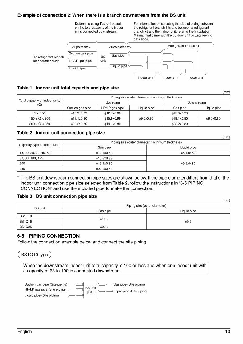
Example of connection 2: When there is a branch downstream from the BS unit
Table 1 Indoor unit total capacity and pipe size
Table 2 Indoor unit connection pipe size
* The BS unit downstream connection pipe sizes are shown below. If the pipe diameter differs from that of the indoor unit connection pipe size selected from Table 2, follow the instructions in “6-5 PIPING CONNECTION” and use the included pipe to make the connection.
Table 3 BS unit connection pipe size
6-5 PIPING CONNECTIONFollow the connection example below and connect the site piping.
(mm)
Total capacity of indoor units(Q)
Piping size (outer diameter x minimum thickness)
Upstream Downstream
Suction gas pipe HP/LP gas pipe Liquid pipe Gas pipe Liquid pipe
Q < 150 φ15.9x0.99 φ12.7x0.80
φ9.5x0.80
φ15.9x0.99
φ9.5x0.80150 ≤ Q < 200 φ19.1x0.80 φ15.9x0.99 φ19.1x0.80
200 ≤ Q ≤ 250 φ22.2x0.80 φ19.1x0.80 φ22.2x0.80
(mm)
Capacity type of indoor unitsPiping size (outer diameter x minimum thickness)
Gas pipe Liquid pipe
15, 20, 25, 32, 40, 50 φ12.7x0.80 φ6.4x0.80
63, 80, 100, 125 φ15.9x0.99
φ9.5x0.80200 φ19.1x0.80
250 φ22.2x0.80
(mm)
BS unitPiping size (outer diameter)
Gas pipe Liquid pipe
BS1Q10φ15.9
φ9.5BS1Q16
BS1Q25 φ22.2
Indoor unit Indoor unit Indoor unit
Gas pipe
Liquid pipe
Determine using Table 1 based on the total capacity of the indoor units connected downstream.
For information on selecting the size of piping between the refrigerant branch kits and between a refrigerant branch kit and the indoor unit, refer to the Installation Manual that came with the outdoor unit or Engineering data book.
To refrigerant branch kit or outdoor unit
Suction gas pipe
HP/LP gas pipe
Liquid pipe
BSunit
Refrigerant branch kit<Upstream> <Downstream>
Suction gas pipe (Site piping)
HP/LP gas pipe (Site piping)
Gas pipe (Site piping)
Liquid pipe (Site piping)Liquid pipe (Site piping)
BS unit(Top)
BS1Q10 type
When the downstream indoor unit total capacity is 100 or less and when one indoor unit with a capacity of 63 to 100 is connected downstream.
English 10
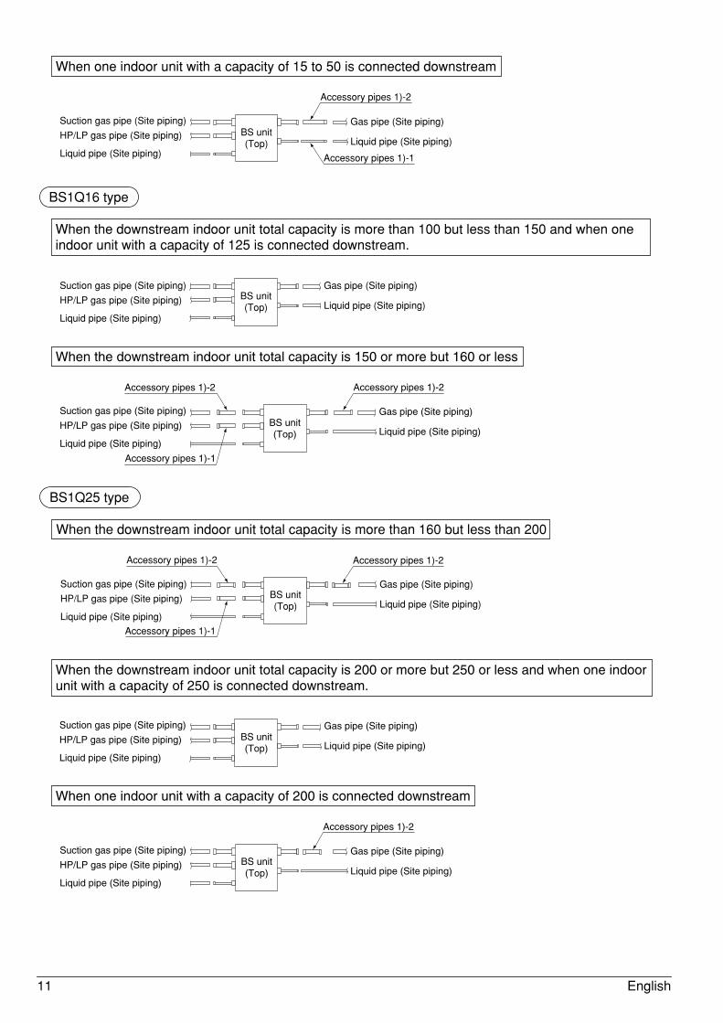
When one indoor unit with a capacity of 15 to 50 is connected downstream
Accessory pipes 1)-2
Accessory pipes 1)-1
Suction gas pipe (Site piping)
HP/LP gas pipe (Site piping)
Liquid pipe (Site piping)
Gas pipe (Site piping)
Liquid pipe (Site piping)BS unit(Top)
Suction gas pipe (Site piping)
HP/LP gas pipe (Site piping)
Gas pipe (Site piping)
Liquid pipe (Site piping)Liquid pipe (Site piping)
BS unit(Top)
BS1Q16 type
When the downstream indoor unit total capacity is more than 100 but less than 150 and when one indoor unit with a capacity of 125 is connected downstream.
When the downstream indoor unit total capacity is 150 or more but 160 or less
Accessory pipes 1)-2
Suction gas pipe (Site piping)
HP/LP gas pipe (Site piping)
Liquid pipe (Site piping)
Gas pipe (Site piping)
Liquid pipe (Site piping)BS unit(Top)
Accessory pipes 1)-2
Accessory pipes 1)-1
Gas pipe (Site piping)
Liquid pipe (Site piping)BS unit(Top)
Suction gas pipe (Site piping)
HP/LP gas pipe (Site piping)
Liquid pipe (Site piping)
Accessory pipes 1)-2 Accessory pipes 1)-2
Accessory pipes 1)-1
BS1Q25 type
When the downstream indoor unit total capacity is more than 160 but less than 200
When the downstream indoor unit total capacity is 200 or more but 250 or less and when one indoor unit with a capacity of 250 is connected downstream.
Suction gas pipe (Site piping)
HP/LP gas pipe (Site piping)
Liquid pipe (Site piping)
Gas pipe (Site piping)
Liquid pipe (Site piping)BS unit(Top)
When one indoor unit with a capacity of 200 is connected downstream
Suction gas pipe (Site piping)
HP/LP gas pipe (Site piping)
Liquid pipe (Site piping)
Gas pipe (Site piping)
Liquid pipe (Site piping)BS unit(Top)
Accessory pipes 1)-2
11 English
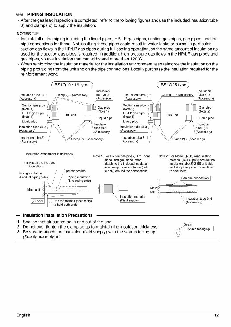
6-6 PIPING INSULATION• After the gas leak inspection is completed, refer to the following figures and use the included insulation tube
3) and clamps 2) to apply the insulation.
NOTES• Insulate all of the piping including the liquid pipes, HP/LP gas pipes, suction gas pipes, gas pipes, and the
pipe connections for these. Not insulting these pipes could result in water leaks or burns. In particular, suction gas flows in the HP/LP gas pipes during full cooling operation, so the same amount of insulation as used for the suction gas pipes is required. In addition, high-pressure gas flows in the HP/LP gas pipes and gas pipes, so use insulation that can withstand more than 120˚C.
• When reinforcing the insulation material for the installation environment, also reinforce the insulation on the piping protruding from the unit and on the pipe connections. Locally purchase the insulation required for the reinforcement work.
Insulation Installation Precautions
1. Seal so that air cannot be in and out of the end.2. Do not over tighten the clamp so as to maintain the insulation thickness.3. Be sure to attach the insulation (field supply) with the seams facing up.
(See figure at right.)
BS1Q10 · 16 type BS1Q25 type
BS unit BS unit
Clamp 2)-2 (Accessory) Clamp 2)-2 (Accessory)Insulation tube 3)-2(Accessory)
Insulation tube 3)-2(Accessory)
Insulation tube 3)-2(Accessory)
Insulation tube 3)-1(Accessory)
Insulation tube 3)-2(Accessory)
Insulation tube 3)-1(Accessory)
Insulation tube 3)-2(Accessory)
Insulation tube 3)-1(Accessory)
Insulation tube 3)-1(Accessory)
Insulation tube 3)-3(Accessory)
Suction gas pipe (Note 1) Gas pipe
(Note 1)
Liquid pipe
Gas pipe (Note 2)
Liquid pipe
HP/LP gas pipe (Note 1)
Liquid pipe
Suction gas pipe (Note 2)HP/LP gas pipe (Note 1)
Liquid pipe
Clamp 2)-2 (Accessory) Clamp 2)-2 (Accessory)
Insulation Attachment Instructions
Piping insulation(Product piping side)
Pipe connection
Insulation material (Field supply)
Seal the connection.Piping insulation(Site piping side)
(1) Attach the included insulation.
(2) Seal (3) Use the clamps (accessory) to hold both ends.
Note 1: For suction gas pipes, HP/LP gas pipes, and gas pipes, after attaching the included insulation tube, wrap more insulation (field supply) around the connections.
Note 2: For Model Q250, wrap sealing material (field supply) around the insulation tube 3)-2 BS unit side and site piping side connections to seal them.
Main unit Main unit
Insulation tube 3)-2(Accessory)
Attach facing upSeam
English 12
7. ELECTRIC WIRING WORK
7-1 GENERAL INSTRUCTIONS• All wiring must be performed by an authorized electrician.• All field supplied parts and materials, electric works must conform to local codes.• Always ground wires. (In accordance with national regulations of the pertinent country.)• Always turn off the power before performing the electric wire installation work.• Follow the “WIRING DIAGRAM” attached to the unit body to wire the outdoor unit and indoor units.• Properly connect wire of the specified wire type and copper thickness. Also use the included clamp to avoid
applying excessive force to the terminal (field wire, ground wire).• Do no let the ground wire should come in contact with gas pipes, water pipes, lighting rods, or telephone
ground wires.• Gas pipes: gas leaks can cause explosions and fire.• Water pipes: cannot be grounded if hard vinyl pipes are used.• Telephone ground and lightning rods: the ground potential when struck by lightning gets extremely high.
• A circuit breaker capable of shutting down the power supply to the entire system must be installed.• This system consists of multiple BS units. Mark each BS unit as unit A, unit B . . . , and be sure the terminal
board wiring to the outdoor unit and indoor unit are properly matched. If wiring and piping between the outdoor unit, BS unit and an indoor unit are mismatched, the system may cause a malfunction.
• Do not turn on the power supply (branch switches, overload interrupters) until all other work is done.
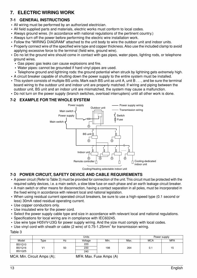
7-2 EXAMPLE FOR THE WHOLE SYSTEM
7-3 POWER CIRCUIT, SAFETY DEVICE AND CABLE REQUIREMENTS• A power circuit (Refer to Table 3) must be provided for connection of the unit. This circuit must be protected with the
required safety devices, i.e. a main switch, a slow blow fuse on each phase and an earth leakage circuit breaker.• A main switch or other means for disconnection, having a contact separation in all poles, must be incorporated in
the fixed wiring in accordance with relevant local and national legislation.• When using residual current operated circuit breakers, be sure to use a high-speed type (0.1 second or
less) 30mA rated residual operating current.• Use copper conductors only.• Use insulated wire for the power cord.• Select the power supply cable type and size in accordance with relevant local and national regulations.• Specifications for local wiring are in compliance with IEC60245.• Use wire type H05VV-U3G for power supply wiring. And the size must comply with local codes.• Use vinyl cord with sheath or cable (2 wire) of 0.75-1.25mm
2 for transmission wiring.
Table 3
MCA: Min. Circuit Amps (A); MFA: Max. Fuse Amps (A)
Units Power supplyModel Type Hz Voltage Min. Max. MCA MFA
BS1Q10BS1Q16BS1Q25
V1 50220
198 264 0.1 15230240
Power supply wiring
Transmission wiring
Switch
Fuse
Outdoor unitPower supply
Power supply
Main switch
Main switch
BS unit
Indoor unit
Remote controller
Cooling/Heating selectable indoor unit
Cooling-dedicated indoor unit
13 English
NOTES• The above Table 3 of Electrical Characteristics refers to one BS unit.• See the Engineering data book for other details.
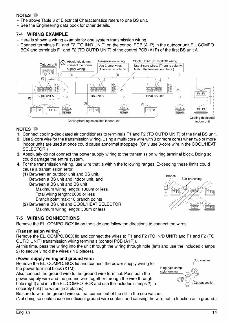
7-4 WIRING EXAMPLE• Here is shown a wiring example for one system transmission wiring.• Connect terminals F1 and F2 (TO IN/D UNIT) on the control PCB (A1P) in the outdoor unit EL. COMPO.
BOX and terminals F1 and F2 (TO OUT/D UNIT) of the control PCB (A1P) of the first BS unit A.
NOTES1. Connect cooling-dedicated air conditioners to terminals F1 and F2 (TO OUT/D UNIT) of the final BS unit.2. Use 2-core wire for the transmission wiring. Using a multi-core wire with 3 or more cores when two or more
indoor units are used at once could cause abnormal stoppage. (Only use 3-core wire in the COOL/HEAT SELECTOR.)
3. Absolutely do not connect the power supply wiring to the transmission wiring terminal block. Doing so could damage the entire system.
4. For the transmission wiring, use wire that is within the following ranges. Exceeding these limits could cause a transmission error.(1) Between an outdoor unit and BS unit,
Between a BS unit and indoor unit, andBetween a BS unit and BS unit
Maximum wiring length: 1000m or lessTotal wiring length: 2000 or lessBranch point max: 16 branch points
(2) Between a BS unit and COOL/HEAT SELECTORMaximum wiring length: 500m or less
7-5 WIRING CONNECTIONSRemove the EL. COMPO. BOX lid on the side and follow the directions to connect the wires.
⟨Transmission wiring⟩Remove the EL. COMPO. BOX lid and connect the wires to F1 and F2 (TO IN/D UNIT) and F1 and F2 (TO OUT/D UNIT) transmission wiring terminals (control PCB (A1P)).At this time, pass the wiring into the unit through the wiring through hole (left) and use the included clamps 2) to securely hold the wires (in 2 places).
⟨Power supply wiring and ground wire⟩Remove the EL. COMPO. BOX lid and connect the power supply wiring to the power terminal block (X1M).Also connect the ground wire to the ground wire terminal. Pass both the power supply wire and the ground wire together through the wire through hole (right) and into the EL. COMPO. BOX and use the included clamps 2) to securely hold the wires (in 2 places).Be sure to wire the ground wire so that comes out of the slit in the cup washer.(Not doing so could cause insufficient ground wire contact and causing the wire not to function as a ground.)
F1F2
F1
F1 F2 F1 F2 F1 F2 F1 F2 F1 F2
F1 F2
F2 F1 F2
F1F2
F1 F2 F1 F2 F1 F2 F1 F2
A
A B C A B C A B C
B
C
A
B
C
A
B
C
(1)
(1)
(1) (1)
(1) (1) (1)
(1)(1)
(2)(2)(2)
Absolutely do not connect the power supply wiring.
Transmission wiringUse 2-core wires.(There is no polarity.)
COOL/HEAT SELECTOR wiringUse 3-core wires. (There is polarity. Match the terminal numbers.)
Cooling/Heating selectable indoor unitCooling-dedicated
indoor unit
Outdoor unit
BS unit A BS unit B Final BS unit
C/H SE
LECT
OR
COOL/HEATSELECTOR
COOL/HEATSELECTOR
COOL/HEATSELECTOR
C/H SE
LECT
OR
C/H SE
LECT
OR
TO IN/D UNIT TO OUT/D UNIT TO IN/D UNIT TO OUT/D UNIT TO IN/D UNIT TO OUT/D UNIT
TO IN/D UNIT TO OUT/D UNIT
F1 F2 F1F2
F1F2
F1F2
F1F2
branchSub-branching
Cut out section
Cup washer
Ring-type crimp style terminal
English 14
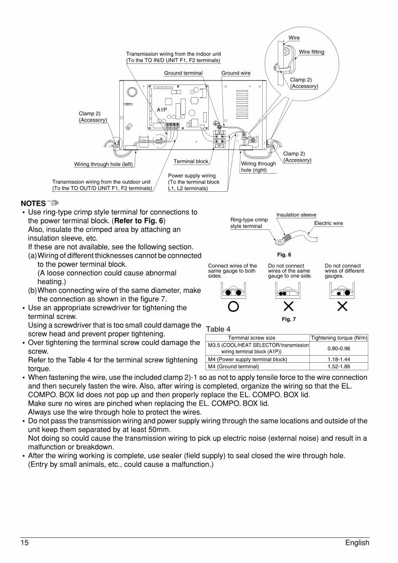
NOTES• Use ring-type crimp style terminal for connections to
the power terminal block. (Refer to Fig. 6)Also, insulate the crimped area by attaching an insulation sleeve, etc.If these are not available, see the following section.(a)Wiring of different thicknesses cannot be connected
to the power terminal block.(A loose connection could cause abnormal heating.)
(b)When connecting wire of the same diameter, make the connection as shown in the figure 7.
• Use an appropriate screwdriver for tightening the terminal screw.Using a screwdriver that is too small could damage the screw head and prevent proper tightening.
• Over tightening the terminal screw could damage the screw.Refer to the Table 4 for the terminal screw tightening torque.
• When fastening the wire, use the included clamp 2)-1 so as not to apply tensile force to the wire connection and then securely fasten the wire. Also, after wiring is completed, organize the wiring so that the EL. COMPO. BOX lid does not pop up and then properly replace the EL. COMPO. BOX lid.Make sure no wires are pinched when replacing the EL. COMPO. BOX lid.Always use the wire through hole to protect the wires.
• Do not pass the transmission wiring and power supply wiring through the same locations and outside of the unit keep them separated by at least 50mm.Not doing so could cause the transmission wiring to pick up electric noise (external noise) and result in a malfunction or breakdown.
• After the wiring working is complete, use sealer (field supply) to seal closed the wire through hole.(Entry by small animals, etc., could cause a malfunction.)
A1P
F1 F2 F1 F2
Transmission wiring from the indoor unit(To the TO IN/D UNIT F1, F2 terminals)
Ground terminal Ground wire
Wire
Wire fitting
Terminal block
Power supply wiring(To the terminal block L1, L2 terminals)
Wiring through hole (right)
Wiring through hole (left)
Transmission wiring from the outdoor unit(To the TO OUT/D UNIT F1, F2 terminals)
Clamp 2)(Accessory)
Clamp 2)(Accessory)
Clamp 2)(Accessory)
TO IN/D UNIT TO OUT/D UNIT
Insulation sleeve
Electric wireRing-type crimp style terminal
Fig. 6
Connect wires of the same gauge to both sides.
Do not connect wires of the same gauge to one side.
Do not connect wires of different gauges.
Fig. 7
Terminal screw sizeM3.5 (COOL/HEAT SELECTOR/transmission
wiring terminal block (A1P))
M4 (Power supply terminal block)M4 (Ground terminal)
0.80-0.96
1.18-1.441.52-1.86
Tightening torque (N/m)
Table 4
15 English
8. INITIAL SETTING• When the refrigerant piping and wire installation work is completed, make the following settings as
required.1. Setting for when connecting the COOL/HEAT SELECTOR to the BS unit.
⟨Setting description⟩Set the input signal from the COOL/HEAT SELECTOR (sold separately) to ON/OFF.
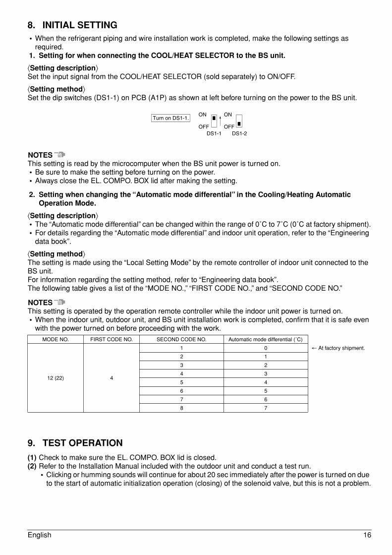
⟨Setting method⟩Set the dip switches (DS1-1) on PCB (A1P) as shown at left before turning on the power to the BS unit.
NOTESThis setting is read by the microcomputer when the BS unit power is turned on.• Be sure to make the setting before turning on the power.• Always close the EL. COMPO. BOX lid after making the setting.
2. Setting when changing the “Automatic mode differential” in the Cooling/Heating Automatic Operation Mode.
⟨Setting description⟩• The “Automatic mode differential” can be changed within the range of 0˚C to 7˚C (0˚C at factory shipment).• For details regarding the “Automatic mode differential” and indoor unit operation, refer to the “Engineering
data book”.
⟨Setting method⟩The setting is made using the “Local Setting Mode” by the remote controller of indoor unit connected to the BS unit.For information regarding the setting method, refer to “Engineering data book”.The following table gives a list of the “MODE NO.,” “FIRST CODE NO.,” and “SECOND CODE NO.”
NOTESThis setting is operated by the operation remote controller while the indoor unit power is turned on.• When the indoor unit, outdoor unit, and BS unit installation work is completed, confirm that it is safe even
with the power turned on before proceeding with the work.
9. TEST OPERATION
(1) Check to make sure the EL. COMPO. BOX lid is closed.(2) Refer to the Installation Manual included with the outdoor unit and conduct a test run.
• Clicking or humming sounds will continue for about 20 sec immediately after the power is turned on due to the start of automatic initialization operation (closing) of the solenoid valve, but this is not a problem.
MODE NO. FIRST CODE NO. SECOND CODE NO. Automatic mode differential (˚C)
12 (22) 4
1 0 ← At factory shipment.
2 1
3 2
4 3
5 4
6 5
7 6
8 7
Turn on DS1-1.ON
OFFDS1-1
ON
OFFDS1-2
English 16
10. WIRING PARTS TABLEA1P................PRINTED CIRCUIT BOARDDS1, DS2 ......DIP SWITCHF1U................FUSE (T, 3,15A, 250V)F2U................FIELD FUSEHAP...............LIGHT EMITTING DIODE (SERVICE MONITOR - GREEN)PS..................SWITCHING POWER SUPPLY (A1P)Q1DI ..............FIELD EARTH LEAKAGE BREAKERX1M...............TERMINAL STRIP (POWER)X1M (A1P).....TERMINAL STRIP (CONTROL)X2M...............TERMINAL STRIP (C/H SELECTOR)Y1E................ELECTRONIC EXPANSION VALVE (SUB COOL)Y2E................ELECTRONIC EXPANSION VALVE (DISCHARGE)Y3E................ELECTRONIC EXPANSION VALVE (SUCTION)Z1C................NOISE FILTER (FERRITE CORE)
CONNECTOR FOR OPTIONAL PARTSX2A................CONNECTOR (WIRING EXTERNAL CONTROL ADAPTOR FOR OUTDOOR UNIT)X38A..............CONNECTOR (ADAPTOR FOR MULTI TENANT)
NOTES)1. THIS WIRING DIAGRAM APPLIES TO THE BS UNIT ONLY.2. : TERMINAL STRIP : CONNECTOR : TERMINAL
: FIELD WIRING PROTECTIVE EARTH3. WHEN USING THE COOL/HEAT SELECTOR (OPTIONAL ACCESSORY), CONNECT IT TO THE
TERMINALS A, B AND C ON X2M.4. AS FOR WIRING TO THE IN/D UNIT (F1)•(F2) AND OUT/D UNIT (F1)•(F2) ON X1M (A1P), REFER
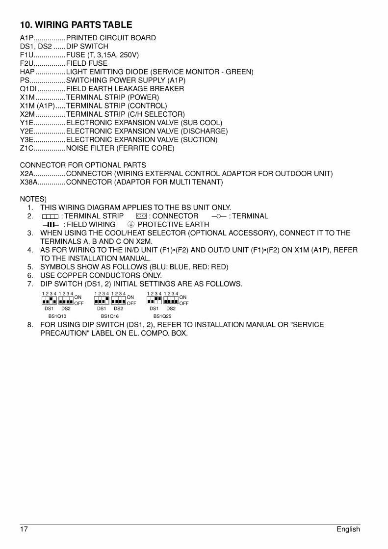
TO THE INSTALLATION MANUAL.5. SYMBOLS SHOW AS FOLLOWS (BLU: BLUE, RED: RED)6. USE COPPER CONDUCTORS ONLY.7. DIP SWITCH (DS1, 2) INITIAL SETTINGS ARE AS FOLLOWS.
8. FOR USING DIP SWITCH (DS1, 2), REFER TO INSTALLATION MANUAL OR "SERVICE PRECAUTION" LABEL ON EL. COMPO. BOX.
DS1 DS2 DS1 DS2 DS1 DS2
1 2 3 4 1 2 3 4 1 2 3 4 1 2 3 4 1 2 3 4 1 2 3 4ONOFF
ONOFF
ONOFF
BS1Q10 BS1Q16 BS1Q25
17 English


4P357812-1 2014.01
Cop
yrig
ht 2
014
Dai
kin