Embed Size (px)
Citation preview

INS159-12
Premier 412/816/832Installation Manual

Contents Premier 412/816/832 Installation Manual
2 INS159-12
Contents
1. System Overview ......................................... 5 System Architecture ......................................................... 5 Control Panels .................................................................. 5 Remote Keypads .............................................................. 5 Zone Expansion Modules ................................................ 6 PC-Com Module ............................................................... 6 ComIP Module .................................................................. 6 Speech Module ................................................................ 6 Radio Receiver Module .................................................... 6
2. Installation.................................................... 7 Installation Sequence ...................................................... 7 Control Panel .................................................................... 7
Mounting ...................................................................................... 7 Wiring the Control Panel .............................................................. 7
Control Panel PCB Layout ............................................... 8 Power Supply Ratings ...................................................... 9
All Models (Large & Small Polymer) ............................................ 9 All Models (Metal) ........................................................................ 9
Connecting AC Mains .................................................... 10 Connecting Devices to the Data Bus ............................ 10
Wiring the Data Bus ................................................................... 10 Cable Type and Distances ......................................................... 10 Installing a Power Supply .......................................................... 10 Overcoming Voltage Drop ......................................................... 11 Use of pull up resistors .............................................................. 11
Installing Remote Keypads ............................................ 12 Keypad Layouts ......................................................................... 12 Remote Keypad Connections .................................................... 12 Remote Keypad Address ........................................................... 12 Keypad Zones ............................................................................ 12 Keypad Output ........................................................................... 12 Keypad Speaker Output (LCDL/LCDLP FMK/SMK) .................. 13 Adjustable Backlighting ............................................................. 13 Keypad Lid Tamper .................................................................... 13
Remote Zone Expander Module .................................... 13 Remote Expander Layout .......................................................... 13 Wiring the Zone Expander ......................................................... 13 Remote Expander Address ........................................................ 13 Remote Expander Zones ........................................................... 13 Zone Expander Outputs ............................................................. 14 Zone Expander Speaker Driver ................................................. 14
Local Zone Expander Module ........................................ 14 Local Expander Layout .............................................................. 14 Local Expander Zones ............................................................... 14 Installing the Local Zone Expander ........................................... 14
Zone Connections .......................................................... 15 Normally Closed ......................................................................... 15 Normally Open ........................................................................... 15 Single EOL - N/C & N/O (Burglary) ............................................ 16 Single EOL - N/O (Fire) .............................................................. 16 Single EOL - N/C ........................................................................ 16 Single EOL - O/C Tamper .......................................................... 16 Single EOL – S/C Tamper .......................................................... 16 Double EOL ................................................................................ 17 Zone Doubling ........................................................................... 17 Triple EOL .................................................................................. 17 Double Pole ................................................................................ 18
2-Wire Smoke Detector .................................................. 18 Speaker/Bell Connections ............................................. 18
Speaker Operation ..................................................................... 18 Siren/Bell Operation ................................................................... 19 Siren/Spk Supervision................................................................ 19
Telephone Line Connections ......................................... 19 Panel Outputs 1 - 8 ......................................................... 19
Output Wiring ............................................................................. 19 Output Supervision .................................................................... 19
3. Commissioning & Troubleshooting ......... 20 Commissioning .............................................................. 20
Troubleshooting .............................................................20 Power Faults ...............................................................................20 Remote Keypads ........................................................................20 Remote Expander .......................................................................20 Zones ..........................................................................................21 Service Faults..............................................................................21 Communicator ............................................................................21 Operation ....................................................................................21
4. Programming the Control Panel .............. 22 Introduction.....................................................................22
Viewing Numeric Data (LED Keypads) .......................................22 Programming Text (LCD Only) ...................................................22
V16 Start up Procedure ..................................................23 Premier RKP8 & 16 LED Keypads ..................................23 Premier LCD Keypads ....................................................23 Program Menus ..............................................................24 Programming Zones .......................................................25
All Zone Options .......................................................26 Zone Type ..............................................................26 Zone Wiring ..............................................................27 Zone Attributes 1 ......................................................27 Zone Attributes 2 ......................................................28 Zone Attributes 3 ......................................................28 Zone Attributes 3 (Key Switch) .................................29 Zone Partitions & Groups .........................................29 Zone Text (LCD Only) ...............................................29 Assign Radio Device ................................................29
Programming Partitions .................................................30 Partition Exit Delay ....................................................31 Partition Entry Delay 1 ..............................................31 Partition Entry Delay 2 ..............................................31 Partition Communication Delay ................................31 Partition Bell Delay ...................................................31 Partition Bell Duration ...............................................31 Partition Options .......................................................31 Partition Auto Arm/Disarm Options ..........................32 Equipment Areas ......................................................32
Programming Global Options ........................................33 System Timers .......................................................35 System Counter/Levels ............................................36 System Control Timers .............................................36 System Options 1 .....................................................36 System Options 2 .....................................................37 System Options 3 .....................................................37 Hardware Options ....................................................38 Auxiliary Input Options .............................................38 Miscellaneous Options 1 -...................................38 Miscellaneous Options 2 -...................................39 Miscellaneous Options 3 -...................................40 EN50131 Options ....................................................40
Programming Remote Keypads .....................................41 Keypad Options 1 .....................................................42 Keypad Options 2 .....................................................42 Keypad Options 3 .....................................................42 Keypad Options 4 .....................................................43
Programming Remote Expanders ..................................44 Expander Partitions ..................................................44 Expander Tones .......................................................44 Expander Volume Level ...........................................44
Programming System Outputs .......................................45 Panel Outputs .......................................................47 Fast Format/Speech Channels ................................47 Expander 1 Outputs .................................................47 Expander 2 Outputs .................................................47 Expander 3 Outputs .................................................47 Keypad Outputs .......................................................47
Output Groups and Types ..............................................47 Output Attributes .........................................................................49
Programming the Communicator ..................................50 Communicator Options ............................................52 ARC 1 Communicator Menu ....................................52 Telephone Numbers - .........................................52

Premier 412/816/832 Installation Manual Contents
INS159-12 3
Account Numbers - ............................................. 53 Protocol Type - ................................................ 53 Dial Attempts - ................................................ 53 Partition Options - ............................................... 53 Reporting Options - ............................................. 54 Pulse Format Options - ....................................... 54 Fast Format Reporting Channels - ..................... 54 Protocol Options - ............................................... 55 ARC 2 Communicator Options ................................ 55 Fast Format Restore Channels ................................ 55 Fast Format Open/Close Channels ......................... 56 Cancel Call Waiting Sequence ................................. 56 Programming Check List ............................................................ 57
Programming Download Options .................................. 58 Download Menu ....................................................... 60 Download Options - ............................................ 60 Call Back Number - ............................................. 60 UDL Passcode - ................................................ 60 Download Dial Attempts - ................................... 60 Ring Count - ...................................................... 60 Com1 Device Type - ........................................... 60 IP Address & Port -.............................................. 61 ComIP Gateway Address - .................................. 61 ComIP Subnet Mask - ......................................... 61 Com2 Device Type - ........................................... 61 Chiron Iris Data Setup - ....................................... 61
Programming Reporting Codes ..................................... 62 Zone Alarm/Restore Codes ...................................... 63 Zone Bypass/Unbypass Codes ............................... 63 Non Zone Alarm/Restore Codes .............................. 63 Contact ID and SIA Codes ......................................................... 63
Programming Users ....................................................... 64 Program User ....................................................... 66 User Options 1 ....................................................... 66 User Options 2 ....................................................... 66 User Options 3 ....................................................... 67 User Text (LCD Only) ............................................... 67 Program Standard Users ......................................... 67 Default ALL Users ..................................................... 67
System Tests & Utilities ................................................. 68 Walk Test .............................................................. 69 Test Speakers & Outputs ......................................... 69 Send Test Call ....................................................... 69 Enable Remote/Engineer Access ............................ 69 Start Call Back ....................................................... 69 Program Time ....................................................... 69 Program Date ....................................................... 69 Program Banner Text (LCD only) ............................. 69 Print 100 Events ....................................................... 69 Log Off Engineer ...................................................... 69
5. Operating the Alarm System .................... 70 Introduction .................................................................... 70
Access Codes ............................................................................. 70 Arming & Disarming the Alarm System ......................... 70
Checking if the System is Ready to Arm .................................... 70 Away Arming ............................................................................... 70 Stay Arming ................................................................................ 70 Cancelling the Arming Process .................................................. 71 Disarming During Entry .............................................................. 71 Disarming when not in Entry ...................................................... 71 Disarming after an Alarm ............................................................ 71 Auto Stay Arming ........................................................................ 71 Changing between Delayed and Instant Stay ............................ 71
Arming and Disarming Partitions................................... 72 Away Arming Partitions............................................................... 72 Stay Arming Partitions ................................................................ 72 Disarming Partitions ................................................................... 72 Changing to another Partition .................................................... 73
Bypassing Zones ............................................................ 73 Manually Bypassing Zones ........................................................ 73 Unbypassing Zones.................................................................... 73 Group Bypass ............................................................................. 74 Quick Bypass and Arm ............................................................... 74
Reset Alarms .................................................................. 75 Last Alarm Log ................................................................ 75 Service Faults ................................................................. 75
Acknowledging a New Service Fault ......................................... 75 View Service Faults .................................................................... 76
Anti-code Reset.............................................................. 77 Toggle Chime On and Off .............................................. 77 Change User Code ........................................................ 77 View Log (LCD Only) ..................................................... 77 Abort Communications .................................................. 77
6. Specifications ............................................ 78 Control Panel ................................................................. 78
All Models Large & Small Polymer ............................................. 78 All Models Metal ......................................................................... 78
Remote Keypads ............................................................ 79 Remote Zone Expander ................................................. 79 Local Zone Expander ..................................................... 79 Safety Notes ................................................................... 79 Standards ....................................................................... 79
EN 50131-1/3/6 Compliance ...................................................... 79 Warranty ......................................................................... 80
7. Quick Reference Guide ............................ 81
8. Standard Defaults & Programming Records .............................................................. 86
Installation Details ......................................................... 86 Zone Details ................................................................................ 86
Programming Worksheets & Defaults .......................... 87 Notes .............................................................................. 99
Index Premier 412/816/832 Installation manual
4 INS159-12
System Overview
Installation
Control Panel PCB Layout
Installing Remote Keypads & Expanders
Zone Connections
Siren/Bell, Telephone and Panel Outputs
Commissioning & Troubleshooting
Programming Menus
Programming Zones
Programming Partitions
Programming Global Options
Programming Remote Keypads
Programming Remote Expanders
Programming System Outputs
Programming the Communicator
Programming Download Options
Programming Reporting Codes
Programming Users
System Tests, Utilities and Using RadioPlus
Operating the Alarm System
Specifications
Quick Reference Guide & Defaults

Premier 412/816/832 Installation Manual System Overview
INS159-12 5
1. System Overview
System Architecture
P remier 412/816/832
O nboa rdC ommunicator/modem
E OL Zone Inputs= 4Pre mier 412
Pre mier 816 Pre mier 832
= 8= 8
Data Bus
6 Programmable 100mA Outputs
2 Programmable 1A Outputs
S iren Driver
Aux Input
6 R emote Ke ypa ds (max)
Alarm R eceivingCentre
Modem
PC and Mode m for Remote Upload/Download
PC -C om
PC and forLocal Upload/Download
PC-C om
P remier 8XE L oc al Zone E xpa nder
Premier B ell ModuleO R
Pre mie r RKP4/8 /16 Remote Keypad
Com1
2 E OL Zone s1 Output(100mA)
Premier LC D/LC DPRemote Keypad
2 E OL Zone s1 Output(100mA)
P re mier LC DL /LC DLPRemote Keypad
S pe aker Driver
Premier RKP8 /16 PlusRemote Keypad
2 E OL Zone s ( )RKP1 6 Plus
8 E OL Zone Inputs
P re mier 8X Remote Zone E xpa nder
2 Programmable 100mA Outputs
S pea ke r Drive r
Re mote E xpandersPremie r 41 2
Premie r 83 2
= 1
= 3Premie r 81 6 = 1
4 5 6
1 2 3
7 8 9 0
Control Panels
The Premier 412, 816, 816 Plus and Premier 832 are highly sophisticated security control panels with Integrated Multi-protocol Digital Communicator/Modem. The control panels have the following features:
Features 412 816 816 Plus
832
Zones 4 8 8 8
Max. Zones when expanded 12 16 16 32
Partitions 2 4 4 4
User Codes 32 32 32 64
Event Log 750 750 750 1000
Mandatory Log Events (EN50131-3) 250 250 250 250
Touch Tone Remote Control
Programmable Aux. Input
Supervised Siren/Bell Output
2 x 1A Supervised Outputs
6 x 100mA Outputs
Printer/UDL Port
Integrated Modem/Communicator
Remote Keypads
The control panels will accept up to a maximum of 6 remote keypads. All remote keypads require a 4-wire connection to the data network and have a built in piezoelectric sounder. The following remote keypad models are available:
Premier RKP4/8/16 A cost effective range of remote keypads with either 4, 8 or 16 zone indicator lights.
• 4-wire connection to data network.
• Built in piezoelectric sounder.
• Dual level back-lighting, normally dim, switching to bright for 8 seconds after any key press
• Dedicated status lights for “Alarm”, “Service”, “Armed” and “Ready”.
Premier RKP8/16 Plus A professional range of LED remote keypads with either 8 or 16 zone indicator lights.
• 2 programmable EOL zones.
• 4-wire connection to data network.
• Built in piezoelectric sounder.

System Overview Premier 412/816/832 Installation Manual
6 INS159-12
• Fully adjustable back-lighting, normally bright, dim or off, changing to bright whenever a keypad is used and during the entry mode
• Dedicated status lights for “Alarm”, “Service”, “Armed”, “Ready”, “Fire”, “Bypass”, “Instant” and “Stay”
Premier LCD & LCDL The Premier LCD remote keypad has a standard 32 character back-lit LCD display, whereas the Premier LCDL has a large 32 character back-lit LCD display.
• 2 programmable EOL zones
• 1 programmable low current (100mA) output
• 4-wire connection to data network.
• Built in piezoelectric sounder.
• Fully adjustable back-lighting, normally bright, dim or off, changing to bright whenever a keypad is used and during the entry mode
• Dedicated status lights for “Power”, “Armed”, “Ready”, “Service” and “Bypass”
• Speaker driver output (Premier LCDL Only).
Premier LCDLP • Premier LCDL keypad with built-in proximity tag reader
Premier LCDP • Premier LCD keypad with built-in proximity tag reader
Premier Elite FMK • Flush Mount LCDLP with built in proximity tag reader
iconic keys.
• Available in various finishes
Premier Elite SMK • Flush Mount LCDLP with built in proximity tag reader
iconic keys.
• Available in various finishes
Zone Expansion Modules
Either system can be expanded using one of the following zone expansion modules:
Premier 8X Remote Zone Expander This module comes supplied in its own enclosure and is connected to the control panel data network to provide remote expansion of the system. This module provides the following additional facilities:
• 8 programmable EOL zones
• 2 programmable low current (100mA) outputs
• Speaker driver output with electronic volume control.
Premier 8XE Local Zone Expander This module comes supplied as a PCB and simply plugs onto the main control panel circuit board. This module provides 8 programmable EOL zones.
PC-Com Module
This module plugs on to the Premier 412, 816 and Premier 832 control panel to provide an RS232 interface, which can be used for:
• Connection of a serial printer to print the event log
• Upload/download the system programming via Wintex UDL software and PC.
ComIP Module
This module plugs on to Com1 or Com2 of the control panel to provide the following:
• Alarm event reporting via TCP/IP (WAN/LAN).
• High speed upload/download of system programming via WAN/LAN using Wintex UDL software.
Speech Module
This module plugs on to the control panel to provide the following:
• 4 recordable messages (12 seconds each).
• Each message can be assigned to a specific output function, e.g. Alarm or Fire.
This manual does not cover the full installation of this device; please refer to the instructions supplied with the Speech Module.
Radio Receiver Module
The control panel will accept either the Texecom Ricochet™ Premier Elite 8XP-W or Premier Elite 32XP-W. The receiver module should be wired to the control panel network to provide the following:
• 32 wireless devices, such as PIR, Door Contacts, Shock Sensors, Remote FOBs etc.
• Ricochet™ Mesh Networking Technology
• RF supervision of each device.
• Battery supervision of each device.
This manual does not cover the full installation of these devices; please refer to the instructions supplied with the radio receiver module.

Premier 412/816/832 Installation Manual Installation
INS159-12 7
2. Installation
Installation Sequence
Before attempting to install the alarm system, read this section. Once you have an overall understanding of the installation sequence, carefully work through each step.
1: Design the Layout Make a rough sketch of the premises to get an idea of where all alarm detection devices, keypads and other modules are to be located.
2: Mounting the Panel The control panel should be mounted in a dry area close to an unswitched AC power source and the incoming telephone line.
You must complete all wiring before connecting the battery, or applying AC to the panel.
Some versions of the control panel are not supplied with an integral mains transformer. If this is the case a suitable external mains transformer will be required (see page 78)
3: Install the Keypads Mount and connect the keypads to the control panel.
4: Zone Wiring Install detection devices and connect to control panel.
5: Other Wiring Complete all other wiring including bells or sirens and telephone line connections.
6: Apply Power to the Control Panel Once steps 1 to 5 are completed, apply power to the control panel. First, connect the red battery lead to the positive terminal and the black lead to negative. Then, connect the AC.
7: Complete the Installation Records & Defaults Worksheets On page 86 you will find “Installation Records and Defaults” worksheets. These worksheets allow you to record all programming data and also lists all program defaults. It is recommended that the worksheets are filled in before attempting to program the system.
8: Program the System Using the Programming Worksheets program the control panel in accordance with the procedures in Section 3.
9: Testing the System Test the system thoroughly to ensure that all features and functions are operating as required.
Control Panel
Mounting Mount the control panel on a flat, plumb wall using at least three appropriate screws. The rear casing has been designed with a central key-hole slot so that mounting is possible without removing the Printed Circuit Board (PCB).
The angled slot in the lower corner has been provided to allow the panel to be levelled easily. If the PCB has to be removed, carefully pull back the two front PCB securing clips, lift the front of the PCB and slide it downward. To replace the PCB simply reverse the above procedure.
It is essential to ensure that none of the fixing slots or cable entries are accessible after fixing.
Mains cabling must be secured (e.g. with a cable tie) to one of the anchor points provided.
Wiring the Control Panel
WARNING: ELECTRICITY CAN KILL BEFORE connecting the control panel
ALWAYS disconnect the supply at the consumer unit. If in ANY doubt consult a qualified electrician.
ONLY connect the mains supply to the mains terminal block, NEVER connect the mains supply directly to the PCB.
The system installation MUST be carried out in accordance with the national safety standards, for example EN 60950: 1992.
ALWAYS refer to National Wiring Regulations when conducting installation.
An appropriate and readily accessible disconnection device (e.g. an unswitched fused spur) MUST be provided as part of the installation.
The disconnection device must NOT be fitted in a flexible cord.
Where identification of the neutral in the mains supply is NOT possible, a two-pole disconnection device MUST be used.
Use mains cable of adequate carrying capacity for the rated current (i.e. at least 0.75mm2).

Programming the Control Panel Premier 412/816/832 Installation Manual
8 INS159-12
Control Panel PCB Layout
1: Earth Ground Connection Earth ground. Connect to earth or an earth rod.
Failure to fit an earth cable may prevent proper operation of the system and will invalidate the Texecom warranty and product approvals.
2: AC Input Connect to a 16.5V transformer.
Do NOT connect the mains supply to the AC input terminals.
3: Battery Connections A 12V rechargeable battery must be connected to these two terminals in order to provide continuous system operation in the event of mains failure. The battery output is protected by fuse F1 (1.6 Amp).
4: Data Bus Connections The data bus terminals provide connections to the remote keypads and Premier 8X Remote Zone Expander. The + and – terminals provide power whilst the T and R terminals are transmit and receive data.
5: Siren/Spk output These terminals are used for driving speakers, sirens or bells. The output can be programmed for speaker driver or for Siren/bell driver (see page 36). This output is supervised, if no warning devices are fitted, either fit a 1KΩ resistor between these two terminals or disable the siren supervision, see page 38.
6: Auxiliary 12V Power These terminals provide auxiliary power for devices that require 12V power. The auxiliary output is protected by fuse F2 (1 Amp).
7: Zone Inputs 1 to 8 These terminals provide the connections to the zone inputs. The Premier 816 and Premier 832 have 8 zone inputs, whereas the Premier 412 has only 4 zone inputs. There are several ways to wire a zone (see page 14). Each zone is fully programmable, see page 25 for information on programming zones.
8: Two-Wire Smoke Detector Enable Set this link as shown when connecting 2-wire smoke detectors to Panel Output 1.
Output 1 is enabled for 2-wire smoke detectors
Output 1 is normal
9: Aux Input This is a programmable input, it can be used for monitoring auxiliary tamper devices etc, see page 38 for programming details.
10: Panel Outputs 1 to 8 These are programmable outputs. Panel outputs 1 and 2 are high current (1 Amp) supervised outputs. If panel outputs 1 or 2 are not used, either fit a 1KΩ resistor between the unused output and Auxiliary 12V + or disable the output supervision, see page 38. Panel outputs 3 to 8 are low current (100mA) outputs.
11: Communication Ports 1 and 2 Serial communication ports 1 and 2, these can be used for third party devices or PC for local downloading.

Premier 412/816/832 Installation Manual Installation
INS159-12 9
12: Load Defaults Short between the centre and either of the outer pins during power up to restore the control panel default program parameters. These pins can also be used to reset the Engineer code back to its default value, see page 69.
Do not leave these pins shorted, otherwise the control panel event log will be erased.
13: Box Tamper Disable Fit link as shown:
Box Tamper Disabled
Box Tamper Enabled
14: Local Zone Expander The Premier 8XE Local Zone Expander can be plugged on to the main PCB. The local expander provides an additional 8 programmable zones (see page 14).
15: Speech Module A four channel Speech Module can be plugged on to the main PCB (SK1). This connector is only fitted on the Premier 816Plus and Premier 832 control panels.
16: Box Tamper Switch Box tamper protection for the main control panel.
17: Power Light On steady when either AC or standby battery is present. Flashes when the on-board communicator is dialling or sending data.
18: Electronic Fuses The PCB is protected using electronic PTC fuses:
• F1 (2.5 Amp) Battery fuse
• F2 (900mA) Auxiliary 12V power fuse
• F3 (900mA) Siren/Bell output fuse
• F4 (900mA) Network fuse
To reset a fuse, remove all load from the protected circuit, wait 10 seconds, then reconnect.
19: Telephone Line Connections Telephone line connections (see page 19).
20: RJ11 Telephone Line Connector An RJ11 connector is provided so that the panel can be connected to the telephone line via a standard RJ11 patch lead.
21: Engineers Keypad Connection An engineers keypad (Premier LCD keypad and interface lead) can be temporarily plugged onto this connector to allow system programming and testing.
22: Network Data Indicator LEDs The red transmit (Tx) LED indicates that data is flowing out of the control panel and normally flashes very quickly. The green receive (Rx) LED indicates that data is flowing into the control panel. The green LED flashes faster as more devices are connected to the data network.
23: Electronic Fuse Fault Indicator LEDs Electronic fuses F2-F4 have red indicator LEDs, which light up when the relevant fuse is open circuit (fault).
24: Battery Kick Start Pins The control panel has a deep discharge protection circuit that prevents the standby battery from being fully discharged. When powering up the control panel without AC Mains (battery only), the centre and either outer pins must be shorted together in order to bring the battery into circuit.
25: Battery Charge Current Selector When using a 7Ah standby battery the charge current selector should be set to 300mA. If a 17Ah battery is connected (metal cabinet only) the selector should be set to the 750mA position.
Power Supply Ratings
All Models (Large & Small Polymer)
Current Current Consumption 50mA
Maximum Current Available
0.3A charge 1.1A
Rated Output
Battery
Arrangement
Battery
Charge
Rated Output (Amps)
12h
1 x 7Ah 0.3A 0.533A
Standby and Recharge Times EN50131-1 Grade 1 Grade 2
Minimum Standby Period 12h 12h Maximum Recharge Time 72 Hrs 72 Hrs
All Models (Metal)
Current Current Consumption 50mA
Maximum Current Available
0.3A charge 1.9A
0.75A charge 1.0A
Rated Output
Battery
Arrangement
Battery
Charge
Rated Output (Amps)
12h 24h 30h 60h
1 x 7Ah 0.3A 0.533A 0.241A 0.183A X
1 x 17Ah 0.3A 1.36A 0.658A 0.516A 0.233A
0.75A 1.0A 0.658A 0.516A 0.233A
Standby and Recharge Times EN50131-1 Grade 1 Grade 2
Minimum Standby Period 12h 12h Maximum Recharge Time 72 Hrs 72 Hrs
30h if MAINS FAIL reported to ARC, otherwise 60h
Jumper Settings Battery
Arrangement Recharge
Time Battery Charge Selector
1 x 7Ah < 24Hrs 0.3 A
1 x 17Ah < 24Hrs 0.75 A < 72Hrs 0.3 A

Programming the Control Panel Premier 412/816/832 Installation Manual
10 INS159-12
Connecting AC Mains
The AC Mains supply is connected to a 3 way ‘Euro Type’ fused terminal block, which is fitted with a 3.15A medium/slow blow fuse.
All other wiring MUST be carried out before AC mains is connected to the control panel.
After connecting the AC Mains, fit the mains cover, this can be found in the spares bag.
Connecting Devices to the Data Bus
Before connecting remote keypads and zone expanders, isolate ALL power from the control panel (AC Mains & Battery). Do not continue if there is still power present on the control panel.
Connecting devices with power still present on the control panel may damage the device or control panel and invalidate any warranty.
Remote keypads and zone expanders are all connected to the same data terminals located at the bottom left hand corner of the control panel and may be connected serially (daisy chain), in parallel (star) or any combination of the two.
Wiring the Data Bus The data bus is made up of four terminals incorporating power and data. To ensure correct operation, all four terminals on the device must be connected to the corresponding terminals on the control panel, or previous device (see page 10 for wiring details). The table below shows each terminal and its description:
Terminal Description
+ +12V Supply
- 0V Supply
T Transmit Data
R Receive Data
Cable Type and Distances For improved immunity to electrical noise Texecom recommend the use of screened 4 core cable. The screen should be twisted together and wired into the (–) terminal at the control panel only.
The maximum recommended distance for devices when using standard 7/0.2 alarm cable is:
• 250m for each branch when using the star (parallel) configuration
• When using a daisy chain (series) configuration the maximum distance will depend on the number of devices connected on the chain. The more devices that are connected, the shorter the distance to the last device (this is due to voltage drop in the cable)
Whichever method of wiring configuration is used, ensure that the voltage between the ‘+’ and ‘–’ terminals at each device is no lower than 10.0V when the system is running on the standby battery.
Installing a Power Supply When a power supply is installed, the 0V connections on the power supply must be connected through to 0V on the control panel and the +12V connection between the control panel and the device must be disconnected (see figure below).
The table below shows maximum cable runs when one keypad or expander is installed using standard 7/0.2 alarm cable with various loads:
Configuration Max. Cable Run
1. Keypad + 2 PIR’s @15mA 250m
2. Expander + 2 PIR’s @15mA 250m
3. Expander + 8 PIR’s @15mA 100m
4. As No. 3 + 16Ω Speaker 30m
L
E
N
To P S U
FUS E 3.15A

Premier 412/816/832 Installation Manual Installation
INS159-12 11
Overcoming Voltage Drop There are several ways to overcome voltage drop:
• Use thicker lower resistance cable. Standard 7/0.2 alarm cable has a resistance of 8Ω per 100m
• Double up on the power connections – this will require using a 6 or 8-core cable rather than a 4-core cable
• Install a power supply to power the device locally, remember to common the two negative connections
Use of pull up resistors Devices lost from the network, or high levels of network errors can sometimes be cured using pull-up resistors.
Poor quality cable and/or installation practices are the most common cause of continued faults with network devices. The diagram details the type and placement of the resistors.
+-
TR
NET
WO
RK
OU
T
C o ntrol P an elNetwork 1 o r 2
+ - T RN E TW O R K O U T
K ey pad orE xpan der
+ - T RN E TW O R K O U T
K ey pad orE xpan der
+ - T RN E TW O R K O U T
K ey pad orE xpan der
C onne c t 1K res is tor betwe en “R ” and “+ ” at
the C ontrol P ane l
1K
1K
C onne c t 1K res is tor betwe en “T ” and “+ ” at
the furthe st network de vic e

Programming the Control Panel Premier 412/816/832 Installation Manual
12 INS159-12
Installing Remote Keypads
Keypad Layouts
TR
+
-
R K P 8/16 P lus Layou t
1
2
3
5
4
4 5 6
1 2 3
7 9 0
-
81
24
3
R KP 4/8/16 Layou t
-
LCD /LCD L/LCD P /LCD LP S MK & F MK L ayout
1
2
3
5
4
67
Address DIL Switch Tamper Switch Piezo Sounder Data Bus Connections Programmable Zones 1 and 2 Speaker Output (Premier LCDL/LCDLP Only) Programmable Output
Remote Keypad Connections The remote keypad is connected to the data bus terminals located at the bottom left hand side of the PCB. (See pages 8 to 10).
Remote Keypad Address Each remote keypad must be assigned a different address using the Address DIL switch (). The table below shows how to set the address:
Address DIL 1 DIL 2 DIL 3 DIL 4
1 On/Off Off Off Off
2 Off On Off Off
3 Off Off On Off
4 Off Off Off On
5 On Off Off On
6 Off On Off On
Keypad Zones The Premier RKP8/16 Plus and all LCD remote keypads have two programmable zone inputs (see page 15 for wiring details). Each zone is also fully programmable (see page 25 for programming details). The table below shows the zone allocation when using the Premier RKP8/16 Plus or Premier LCD remote keypads:
Address Premier 412 Premier 816/832
Zone 1 Zone 2 Zone 1 Zone 2
1 Zone 05 Zone 06 Zone 09 Zone 10
2 Zone 07 Zone 08 Zone 11 Zone 12
3 Zone 09 Zone 10 Zone 13 Zone 14
4 Zone 11 Zone 12 Zone 15 Zone 16
5 N/A N/A N/A N/A
6 N/A N/A N/A N/A
The onboard remote keypad zones are not seen by the system until they have been enabled. To enable the onboard keypad zones (see page 43 for details).
Keypad Output All Premier LCD remote keypads have one programmable output, which can be used to drive auxiliary devices such as LED’s, sounders or relays etc. Wire as per Panel Outputs shown on page 19 (see page 47 for programming details).

Premier 412/816/832 Installation Manual Installation
INS159-12 13
Keypad Speaker Output (LCDL/LCDLP FMK/SMK) The Premier LCDL and LCDLP keypads has an output that can be used for driving up to one 8Ω or two 16Ω loudspeakers (see page 18 for wiring details).
The speaker volume is also fully adjustable (see page 36 for details).
Adjustable Backlighting To adjust the keypad backlighting press the YES key, then with the YES key still pressed use to increase or decrease the backlighting until the required brightness is achieved, then release both keys.
The backlight can only be adjusted when the keypad is not in a menu.
Keypad Lid Tamper The lid tamper of each keypad can be disabled if required using the relevant keypad option in the Keypad Options 4 menu (see page 43 for details).
Remote Zone Expander Module
The Premier 8X Remote Zone Expander provides 8 additional detection zones, two programmable outputs and a speaker driver output.
Remote Expander Layout
Data Bus Connections Programmable Zone Inputs Auxiliary 12V Programmable Outputs 1 and 2 Speaker Driver Output Power LED Disable Tamper Jumper Tamper Switch Address DIL Switch
Wiring the Zone Expander The Remote Zone Expansion Module is connected to the data bus terminals located at the bottom left hand side of the PCB. (See pages 8 to 10).
Remote Expander Address Each remote expander must be assigned a different address using the Address DIL switch (). The table below shows how to set the address:
Address DIL 1 DIL 2 DIL 3 DIL 4
1 On/Off Off Off Off
2 Off On Off Off
3 Off Off On Off
Only one remote expander can be connected to the Premier 412 & 816 control panels (Address = 1).
Remote Expander Zones The Premier 8X Remote Expander has eight programmable zone inputs (see page 15 for wiring details). Each zone is also fully programmable (see page 25 for programming details).
The table below shows the system zone allocation when one or more modules are installed:
Address Remote Expander Zone Inputs
Z1 Z2 Z3 Z4 Z5 Z6 Z7 Z8
1 09 10 11 12 13 14 15 16
2 17 18 19 20 21 22 23 24
3 25 26 27 28 29 30 31 32
When the system is expanded above 8 zones, it MUST be fitted with a suitable remote keypad. For systems up to 16 zones a Premier RKP16 or Premier RKP16 Plus should be installed. For systems above 16 zones a LCD remote keypad should be installed.
The system will only support one type of expansion device for zones 09 - 16, i.e., you can fit either a Premier 8X Remote Expander (Address = 1) or a Premier 8XE Local Expander, you cannot fit both.
Programming the Control Panel Premier 412/816/832 Installation Manual
14 INS159-12
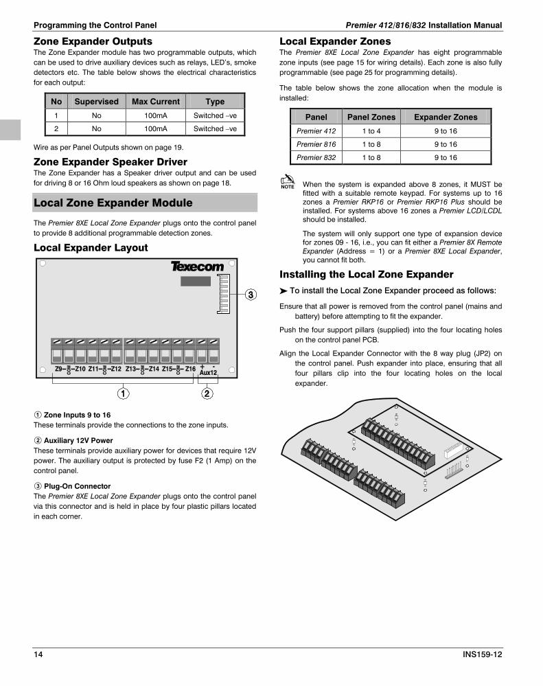
Zone Expander Outputs The Zone Expander module has two programmable outputs, which can be used to drive auxiliary devices such as relays, LED’s, smoke detectors etc. The table below shows the electrical characteristics for each output:
No Supervised Max Current Type
1 No 100mA Switched –ve
2 No 100mA Switched –ve
Wire as per Panel Outputs shown on page 19.
Zone Expander Speaker Driver The Zone Expander has a Speaker driver output and can be used for driving 8 or 16 Ohm loud speakers as shown on page 18.
Local Zone Expander Module
The Premier 8XE Local Zone Expander plugs onto the control panel to provide 8 additional programmable detection zones.
Local Expander Layout
Zone Inputs 9 to 16 These terminals provide the connections to the zone inputs.
Auxiliary 12V Power These terminals provide auxiliary power for devices that require 12V power. The auxiliary output is protected by fuse F2 (1 Amp) on the control panel.
Plug-On Connector The Premier 8XE Local Zone Expander plugs onto the control panel via this connector and is held in place by four plastic pillars located in each corner.
Local Expander Zones The Premier 8XE Local Zone Expander has eight programmable zone inputs (see page 15 for wiring details). Each zone is also fully programmable (see page 25 for programming details).
The table below shows the zone allocation when the module is installed:
Panel Panel Zones Expander Zones
Premier 412 1 to 4 9 to 16
Premier 816 1 to 8 9 to 16
Premier 832 1 to 8 9 to 16
When the system is expanded above 8 zones, it MUST be fitted with a suitable remote keypad. For systems up to 16 zones a Premier RKP16 or Premier RKP16 Plus should be installed. For systems above 16 zones a Premier LCD/LCDL should be installed.
The system will only support one type of expansion device for zones 09 - 16, i.e., you can fit either a Premier 8X Remote Expander (Address = 1) or a Premier 8XE Local Expander, you cannot fit both.
Installing the Local Zone Expander
To install the Local Zone Expander proceed as follows:
Ensure that all power is removed from the control panel (mains and battery) before attempting to fit the expander.
Push the four support pillars (supplied) into the four locating holes on the control panel PCB.
Align the Local Expander Connector with the 8 way plug (JP2) on the control panel. Push expander into place, ensuring that all four pillars clip into the four locating holes on the local expander.

Premier 412/816/832 Installation Manual Installation
INS159-12 15
Zone Connections
Each zone on the system is fully programmable to allow for maximum flexibility (see page 25 for Zone Programming details). The program options for a zone will also determine how the zone may be wired. The following wiring options are available:
Type Zone Status Response
Normally Closed < 10K Secure
> 10K Active
Normally Open < 10K Active
> 10K Secure
Single EOL - N/C & N/O (Burglary)
< 1K Active
1K - 4.7K Secure
> 4.7K Active
Single EOL - N/O (Fire)
< 1K Active
1K - 4.7K Secure
> 4.7K Trouble
Single EOL - N/C
< 2K Trouble
1K - 4.7K Secure
> 4.7K Active
Single EOL - O/C Tamper
< 1K Secure
1K - 4.7K Active
> 4.7K Tamper
Single EOL - S/C Tamper
< 1K Tamper
1K - 4.7K Secure
> 4.7K Active
Double EOL
< 1K* Tamper
1K - 4K* Secure
4K - 20K Active
> 20K Tamper
Zone Doubled
< 1K Zones A & B Trouble
1K - 2K Zones A & B Secure
2K - 4K Zone A Violated
4K - 6K Zone B Violated
> 6K Zones A & B Violated
Triple EOL < 1K* Tamper
1K - 4K* Secure
4K - 6K Trouble (Fault)
6K - 8K Active
8K - 20K Trouble (Masked)
> 20K Tamper
* This value may vary depending on the country code variant.
Normally Closed Use this wiring configuration when connecting normally closed detection devices to the zone. Ensure that the zone is programmed for Normally Closed operation (see page 27). The zone must be wired as follows:
Normally Open Use this wiring configuration when connecting normally open detection devices to the zone. Ensure that the zone is programmed for Normally Open operation (see page 27). The zone must be wired as follows:

Programming the Control Panel Premier 412/816/832 Installation Manual
16 INS159-12
Single EOL - N/C & N/O (Burglary) Use this wiring configuration when connecting a mixture of normally closed and normally open detection devices to the zone. Ensure that the zone is programmed for Single EOL - N/C & N/O operation (see page 27). The zone must be wired as follows:
Single EOL - N/O (Fire) Use this wiring configuration when connecting a 4-wire smoke detector to the zone. Ensure that the zone is programmed for Single EOL - N/O (Fire) operation (see page 27). The zone must be wired as follows:
Single EOL - N/C Use this wiring configuration when connecting just normally closed detection devices to the zone. Ensure that the zone is programmed for Single EOL - N/C operation (see page 27). The zone must be wired as follows:
Single EOL - O/C Tamper Use this wiring configuration when connecting just normally closed detection devices to a zone and when a tamper response is required in the event of an open circuit. Ensure that the zone is programmed for Single EOL - O/C Tamper operation (see page 27). The zone must be wired as follows:
Single EOL – S/C Tamper Use this wiring configuration when connecting just normally closed detection devices to the zone and when a tamper response is required in the event of a short circuit. Ensure that the zone is programmed for Single EOL - S/C Tamper operation (see page 27). Wire Single EOL - S/C Tamper zones as shown for Single EOL - N/C.

Premier 412/816/832 Installation Manual Installation
INS159-12 17
Double EOL Use this wiring configuration when connecting detection devices to a zone that requires alarm/tamper monitoring. Ensure that the zone is programmed for Double EOL operation (see page 27). The zone must be wired as follows:
Zone Doubling This wiring option allows you to wire two detection devices into one set of zone connections. However, the system will treat each device, as if it were connected to a separate zone, i.e., each device is fully programmable.
When using this configuration, the system must be fitted with the appropriate keypad, Premier RKP16 on the Premier 816 and the Premier RKP8 on the Premier 412.
When a zone is configured for “Zone Doubled” it must be wired as follows:
The following table shows how each physical zone is mapped when using the “Zone Doubled” configuration:
Premier 412
Panel Zone Zone A Zone B
1 1 5
2 2 6
3 3 7
4 4 8
Premier 816/832
Panel Zone Zone A Zone B
1 1 9
2 2 10
3 3 11
4 4 12
5 5 13
6 6 14
7 7 15
8 8 16
Zones above 9 on either the Premier 8X/8XE Expander MUST not be configured for “Zone Doubled”.
The Premier 8X/8XE Expander cannot be used on the Premier 816/832 control panels if any of zones 1 - 8 are configured as “Zone Doubled”.
Triple EOL This wiring option is designed to be used with Texecom detectors that support Triple EOL (T-EOL) wiring. Ensure that the zone is programmed for Triple EOL operation (see page 27). The zone must be wired as follows:

Programming the Control Panel Premier 412/816/832 Installation Manual
18 INS159-12
Triple EOL wiring can only be used on remote keypads and remote expanders that are fitted with V7.1 software or above..
Double Pole This wiring configuration can only be used on the Premier LCD/LCDL remote keypads. It provides monitoring for alarm and tamper using normally closed detection devices. Ensure that the zone is programmed for Double EOL operation (see page 27). The zone must be wired as follows:
2-Wire Smoke Detector
Compatible 2-wire smoke detectors such as the ESL429AT or System Sensor 2100TS can be connected as shown:
Panel Output 1 must be enabled for 2-wire smoke detection (see page 36 for details).
The jumper link fitted across JP1 (Enabled 2-Wire Smoke Det.) MUST be removed.
The maximum number of detectors is 20.
Speaker/Bell Connections
The Siren/Spk output terminals on the main PCB can be configured for Speaker or Siren/Bell operation.
Speaker Operation When configured as speaker operation the output can be used for driving 8 or 16 Ohm loud speakers as shown:
The Siren/Spk output must be enabled for speaker driver (see page 36 for details).

Premier 412/816/832 Installation Manual Installation
INS159-12 19
Siren/Bell Operation When configured as bell operation the output terminals provide up to 750mA of power for driving bells as shown:
For EN50131 & INCERT Installations the bell Aux/Tamper must be wired to a zone.
The Siren/Spk output must be enabled for bell driver (see page 37 for details).
Siren/Spk Supervision The Siren/Spk output is supervised, if no warning devices are fitted, either disable Siren Supervision (see page 38 for details) or connect a 1KΩ resistor between the Siren terminals as shown:
Telephone Line Connections
The control panel has a built in digital communicator and modem, which is used for communicating with an alarm receiving centre and for downloading. If either of these features are used, a telephone line must be connected to the control panel as shown:
Failure to fit an earth cable may prevent proper operation of the system and will invalidate the Texecom warranty and product approvals.
Panel Outputs 1 - 8
The control panel has eight programmable outputs, which can be used to drive auxiliary devices such as relays, LED’s, smoke detectors etc. The table shows the electrical characteristics for each output:
Panel Outputs
No Supervised Max Current Type
1 Yes 1 Amp Switched –ve
2 Yes 1 Amp Switched –ve
3 No 100mA Switched –ve
4 No 100mA Switched –ve
5 No 100mA Switched –ve
6 No 100mA Switched –ve
7 No 100mA Switched –ve
8 No 100mA Switched –ve
Output Wiring The figure below shows some typical wiring examples:
Output Supervision Panel outputs 1 and 2 are supervised, if either output is unused, either disable the relevant output supervision (see page 38 for details) or connect a 1KΩ resistor between the relevant output terminal and Auxiliary 12V+ as shown:

Programming the Control Panel Premier 412/816/832 Installation Manual
20 INS159-12
3. Commissioning & Troubleshooting
Commissioning
Once ALL connections have been made to the control panel and power is ready to be applied, you should read this section before continuing.
The control panel leaves the factory with default settings. For a complete list of factory default settings, please refer to the programming worksheets from page 86.
• Connect the black battery lead to the negative (–) terminal of the standby battery and the red battery lead to the positive (+) terminal of the standby battery. The green power light on the main PCB will flash whilst the default values are being loaded.
• If the system has gone into an alarm condition, enter the default Master User code . The alarm tone will then stop.
• To access the Engineer Programming Menu, enter the default Engineer code and press followed by . All the zone lights will illuminate.
• Panels with V16 or later firmware installed will use the start-up procedure found on page 23
• Confirm Devices see page 22
• Program the system date and time, see page 69.
• Select the Language, see page 36.
• Select the Country Code, see page 36.
• Program the system as described in the next section (Programming the Control Panel).
• Perform a walk test as described on page 69. Remember that some powered detectors (e.g. PIRs and combined technology detectors) take several minutes to warm up and become operational.
• Test the internal sounder, external sounder and strobe as described on page 69.
• Replace the lid and secure with the two lid screws supplied - do not over-tighten.
• Replace the screw covers.
• Press to leave the programming menus. All the zone lights will turn off.
• The Service light will be flashing to indicate that action is required. Switch on the mains supply to the control panel. The Service light will stop flashing and stay on continuously.
Installation is now complete and the system is ready for use.
Troubleshooting
Power Faults No Power to Unit (mains only) • Check the mains block fuse and replace if blown.
• Check for any loose wires at the mains block, the transformer and the AC terminals on the PCB.
• Check the mains block is connected correctly; live to live (brown), neutral to neutral (blue).
No Power to Unit (battery only) • Make sure the “Kick Start” pins have been shorted together.
• Check for any loose wires at the BATT terminals on the PCB.
• Check that the battery wires are connected correctly; red from BATT+ to the battery positive [+], black from BATT- to the battery negative [–].
Remote Keypads Keypad Does Not Operate at All • Check that the remote keypad is wired correctly from the
control panel.
• Check that the network fault indicator is off. If the indicator is on, the electronic fuse has activated indicating a short circuit across the [+] and [–] of the network terminals.
Keypad Does Not Accept Access Codes • If the system has more than one remote keypad check that
each keypad is addressed differently, see page 12 for details. The address of a keypad can be checked by pressing the and keys together, the address is displayed by the relevant zone light.
• Check that the remote keypad is wired correctly.
• If the remote keypad is on a cable run that is longer than 100m, check the voltage between the [+] and [–] terminals at the remote and ensure that it measures no less than 10.0V.
• Check that you are using the correct Access code. The default Engineer code is and the default Master User code is .
• Check that the User code you are using is not “Time Locked”, if the User code is time locked then the Access code will only be accepted when Control Timer 1 is off, see page 66 for further details.
Keypad Does Not Generate Alarm Tones etc. • Each keypad can be configured so that the alarm, entry, exit,
chime tones etc. can be enabled or disabled. Check that the keypad has been programmed correctly, see page 42 for details.
Keypad Emergency Keys Do Not Operate • Each keypad can be configured so that the emergency keys
FIRE, POLICE and MEDICAL can be enabled or disabled. Check that the keypad has been programmed correctly, see page 42 for details.
Remote Expander Expander Does Not Operate at All • Check that the expander is wired correctly from the control
panel.
• Check that the network fault indicator is off. If the indicator is on, the electronic fuse has activated indicating a short circuit across the [+] and [–] of the network terminals.
System Does Not Recognise Zones 9 to 16 • If the expander is on a cable run that is longer than 100m,
check the voltage between the [+] and [–] terminals at the remote and ensure that it measures no less than 10.0V.

Premier 412/816/832 Installation Manual Commissioning & Troubleshooting
INS159-12 21
The Speaker Output Does Not Work • The expander can be configured so that the alarm, entry, exit,
chime tones etc. can be enabled or disabled. Check that the expander has been programmed correctly, see page 44 for details.
• The speaker volume on the expander is electronically adjustable. Check the volume is set to the desired level, see page 44 for details.
Zones One or More Zones Show an Alarm • Each zone on the system can be configured for different wiring
options. Check that the zones are programmed for the correct wiring configuration, see page 27 for further details.
• Check that the zone is wired correctly, see page 15 for further details.
Service Faults If the Service light is on or flashing then the system has detected one or more fault conditions, for details on how to view and acknowledge Service Faults see page 75.
On Power-Up the Service Light is On • When the system is powered-up the system date and time are
incorrect. This will cause a Date/Time Loss fault, to clear this fault, program the system date and time, see page 69.
• If the battery presence check is enabled the system will check the battery every 30 seconds. If the system does not have a battery connected then a battery fault will be generated. To clear this fault either connect a battery or disable the battery presence check, see page 36.
• Panel outputs 1 and 2 are supervised outputs, if you have not connected a device to either of these outputs the system will generate an output fault. To clear this fault either fit 1K load resistors between the outputs and +12V, see page 19 or disable the monitoring of outputs 1 and 2, see page 38.
• The Siren output is a supervised output, if you have not connected a device to this output the system will generate a siren fault. To clear this fault either fit 1K load resistors between the siren terminals, see page 19 or disable the monitoring of the siren output, see page 38.
Communicator The Communicator Will Not Dial • By default the communicator is disabled, check that the
communicator is enabled, see page 52.
• Check that the telephone line has been correctly wired to the control panel.
• Check that the primary telephone number is programmed correctly, see page 52.
• Check that the primary account number is programmed correctly, see page 53.
• Check that the primary protocol is programmed correctly, see page 53.
• Check that the primary dial attempts is not programmed as zero, see page 53.
• Check that the primary reporting partitions have been programmed correctly, see page 53.
• Check that the primary reporting options have been programmed correctly, see page 54.
Communicator Dials But Does Not Communicate • Check that the primary telephone number is programmed
correctly, see page 52.
• Check that the primary account number is programmed correctly, see page 53.
• Check that the primary protocol is programmed correctly, see page 53.
• If you are using either Pulse or Express formats check that the protocol is configured correctly, see page 54.
Operation The System Will Not Allow Arming • Check that there are no outstanding Service Faults, see page 75.
• Check that there are no outstanding alarms that require resetting, see page 75.
• Check that the User code has been programmed to allow arming, see page 66.
• Check that the User code has been assigned to the correct partition(s), see page 66.
• If the User code is programmed for “Local Partition Access Only” (see page 67) then ensure that the keypad that is being used is assigned to the correct partition, see page 42.
The System Will Not Allow Disarming • Check that the User code has been programmed to allow
disarming, see page 66.
• Check that the User code has been assigned to the correct partition(s), see page 66.
• If the User code is programmed for “Local Partition Access Only” (see page 67) then ensure that the keypad that is being used is assigned to the correct partition, see page 42.

Programming the Control Panel Premier 412/816/832 Installation Manual
22 INS159-12
4. Programming the Control Panel
Introduction
All engineers should read this section carefully so as to familiarise themselves with the programming of the control panel.
The programming menus can only be accessed when the control panel is fully disarmed. Enter the default Engineer code and press followed by to access the program menus:
E nte r E n gin ee rs co de
T he n pre ss the n
All Z on e l ig h ts li t a ndR e ady l ig h t fla sh es
E nte r me n u co m ma nd
3
A programming menu is selected by entering a two-digit menu code. On completion of each menu option, the system reverts to the main programming menu, allowing other programming menu options to be accessed.
To exit the programming menu enter or press the key, the system will revert to normal operation:
All Z on e l ig h ts li t a nd l ig h t fla sh esR ea dy
To exit pro g ra mm in g m o de ,e nte r o r pre ss
All zo ne s clea r an d l ig h t o n .R ea dy
LC D s ho ws ban ne r texta nd tim e/date .
If the “EN 50131-1 Requirements” option is programmed as enabled (see page 37) the Engineer code will only be accepted after a user has authorised Engineer access. For
information on complying with EN 50131-1 please refer to page 79.
Viewing Numeric Data (LED Keypads) When programming numeric data, the value of the data may be viewed by pressing the key. The keypad will flash the value in sequence using the following lights:
Alarm = 0 Zone 5 = 5 Zone 1 = 1 Zone 6 = 6 Zone 2 = 2 Zone 7 = 7 Zone 3 = 3 Zone 8 = 8 Zone 4 = 4 Armed = 9
Programming Text (LCD Only) Text is programmed in a similar way to mobile phones. Characters are selected by pressing the corresponding key the appropriate number of times (to select a character on the same key, press to move the cursor along).
The table below shows the keys to use and the characters that are assigned to them:
Key Characters
. , ? ! 1 @ “ - &
a b c 2 A B C
d e f 3 D E F
g h i 4 G H I
j k l 5 J K L
m n o 6 M N O
p q r s 7 P Q R S
t u v 8 T U V
w x y z 9 W X Y Z
_ 0 , # * Custom characters
Move cursor left and right
Backspace (delete)
Accept text

Premier 412/816/832 Installation Manual Programming the Control Panel
INS159-12 23
V16 Start up Procedure
V16 sees a new start-up procedure allowing selection of the control panel language, loading specific country defaults and confirming devices connected to the panel network at start-up.
Premier RKP8 & 16 LED Keypads
For LED keypads there is no change to the current operation. Bypassing the requirement to set the language and country code at initial power up is as follows.
• Power up the panel • Enter the default engineers code • Press then 9
You are now in the programming menu and can continue as you did with previous versions of the panel.
Premier LCD Keypads
As with LED keypad operation, the requirement to set the language and country code can be bypassed. The procedure is identical to that shown for LED keypads.
On powering up the panel the following sequence will be presented. You can exit this procedure at anytime by using the keys detailed in the Options column.
Action Display Options
Enter the default engineers code
Press takes you to the Arming Menu Press takes you to the Confirm Devices Menu Press takes you to the Confirm Devices Menu
Press and use the key to select the desired language
Press takes you to the Confirm Devices Menu Press takes you to the Confirm Devices Menu Press takes you to the Confirm Devices Menu
Press to confirm Language
Press takes you to the Arming Menu Press takes you to the Confirm Devices Menu Press takes you to the Confirm Devices Menu
Press and use the numeric keys to enter the desired country code.
Press takes you to the Confirm Devices Menu Press takes you to the Confirm Devices Menu
The panel will now load the defaults for the country code selected.
Press takes you to the Arming Menu Press takes you to the Programming Menu Press takes you to the Programming Menu
Press and check that all devices installed are shown.
Press takes you to day mode. You will be prompted to confirm devices when you log in again.
Press .
Press takes you to day mode. You will be prompted to confirm devices when you log in again.
Press .
Press takes you to the Arming Menu Press takes you to the Arming Menu
Press and use the numeric keys to enter the correct time.
Press takes you to the Programming Menu Press takes you to the Programming Menu
You will be prompted to programme the correct date
Press takes you to the Arming Menu Press takes you to the Arming Menu
Press and use the numeric keys to enter the correct date.
Press takes you to the Programming Menu Press takes you to the Programming Menu
You are now at the Programming Menu
Press takes you to day mode Press takes you to day mode
If confirm devices is not carried out you will be prompted every time you login as an engineer to carry out this function. If the date & time are not set then the engineer or user will be prompted when they login, and each time until the date and time are set.

Programming the Control Panel Premier 412/816/832 Installation Manual
24 INS159-12
Program Menus
Menu Function Page
Programming Zones
All Zone Options 26
Zone Type 26
Zone Wiring 27
Zone Attributes 1 27
Zone Attributes 2 28
Zone Attributes 3 28
Zone Partitions & Groups 29
Zone Text 29
Assign Radio Device 29
Programming Partitions
Partition Exit Time 31
Partition Entry Delay 1 Time 31
Partition Entry Delay 2 Time 31
Partition Communicator Delay 31
Partition Bell Delay 31
Part Bell Duration 31
Partition Options 31
Partition Auto Arm/Disarm 32
Equipment Areas 32
Programming Global Options
System Timers 35
System Counters/Levels 36
System Control Timers 36
System Options 1 36
System Options 2 37
System Options 3 37
Hardware Options 38
Auxiliary Input Options 38
- Miscellaneous Options 1 38
- Miscellaneous Options 2 38
- Miscellaneous Options 3 38
EN50131 Options 39
Programming Remote Keypads
Keypad Options 1 42
Keypad Options 2 42
Keypad Options 3 42
Keypad Options 4 43
Programming Remote Expanders
Expander Partitions 44
Expander Tones 44
Expander Volume Level
44
Menu Function Page
Programming System Outputs
Panel Outputs 47
Fast Format Channels 47
Expander 1 Outputs 47
Expander 2 Outputs 47
Expander 3 Outputs 47
Keypad Outputs 47
Programming The Communicator
Communicator Options 52
ARC 1 Communicator Options 52
ARC 2 Communicator Options 55
Fast Format Restore Channels 55
Fast Format Open/Close Channels
56
Cancel Call Waiting 56
Programming Download Option
Download Menu 60
Programming Reporting Codes
Zone Alarm/Restore Codes 63
Zone Bypass/Unbypass Codes 63
Non Zone Alarm/Restore Codes 63
Programming Users
Program User 66
User Options 1 66
User Options 2 66
User Options 3 67
User Text 67
Program Standard Users 67
Default All Users 67
System Tests and Utilities
Walk Test 69
Test Speakers and Outputs 69
Send Test Call 69
Enable Download Access 69
Start Call Back 69
Program Time 69
Program Date 69
Program Banner Text 69
Print 100 Events 69
Log Off Engineer 69

Premier 412/816/832 Installation Manual Programming the Control Panel
INS159-12 25
Programming Zones
L ed K eyO ffO nS low F la shF ast F la sh
E nte r E n gin ee rs co de
Th e n pre ss the n
Z o n e Ty pe s
N u ll D elay 1 D elay 2 In te rior F o llowe r In te rior In stan t P e rim ete r In sta nt F ir e P A S ilen t P A Au dible M edic al 2 4-H o u r Ta m pe r Tr ou ble 2 4-H o u r - G a s 2 4-H o u r - W a te r 2 4-H o u r - H ig h Tem p 2 4-H o u r - L o w Te mp M om e nta ry K ey switch M ainta in ed K e yswitch P u sh To S e t
C ontinue s onNe xt Page
All Zone O ptionsE n ter Z o n e TypeE n ter W irin g TypeS e le ct Attribu tes 1S e le ct Attribu tes 2S e le ct Attribu tes 3S e le ct P arti tio ns /G rou ps
E n te r Z o n e N u mbe r.
W irin g Ty pes
N or ma lly Clo sed N or ma lly O pen S ing le E O L - N /C & N/O (B u rg lary ) S ing le E O L - N /O (F ire ) S ing le E O L - N /C S ing le E O L - O /C Tam per S ing le E O L - S /C Tam per D ou ble E O L Z o ne Do u ble d
Triple E O L
E nte r W iring Type
: U se to scr ol l typethe n pre ss
-
L C D
Zone Wiring
E n te r Z o n e N u mbe r.
E n ter Z o n e Type
: U se to scr ol l typethe n pre ss
L C D
Zone Ty pe
E n te r Z o n e N u mbe r.
Z o n e A ttribu te s 2
E n able Ma n ua l B y pass E n able S ta y B ypa ss E n able F or ce A rming E n able Q u ic k R e spon se Time E n able C ro ss Z o ning E n able S o a k Test E n able S win g e r S hu tdo wn E n able D ou ble K n oc k
U se k ey s - tosele ct/dese le ct Attribu tes .
T he n pre ss o r
Zone Attributes 2
E n te r Z o n e N u mbe r.
Z o n e A ttribu te s 1
E n able Ins ta n t In te rn als E n able B e ll D elaye d B el l P u ls ed B e ll E n able Ins ta n t S tro be E n able U ser C h im e E n able Tra n smiss io n D elay E n able Tra n smiss io n
Zone Attributes 1
E n te r Z o n e N u mbe r.
U se k eys - tosele ct/dese le ct Attribu tes .
T he n pre ss o r
3
3
3
3
3
3
3
3
3
3
3
3

Programming the Control Panel Premier 412/816/832 Installation Manual
26 INS159-12
FromPrevious Pa ge
Z o n e P a r titio n s & B y pas s G r o u ps
E n abled for P a rtitio n 1 E n abled for P a rtitio n 2 E n abled for P a rtitio n 3 E n abled for P a rtitio n 4 E n abled for B ypass G r ou p 1 E n abled for B ypass G r ou p 2 E n abled for B ypass G r ou p 3 E n abled for B ypass G r ou p 4
U se k ey s - tose le ct/dese le ct Attribu tes .
T he n pr ess o r
Zone Pa rtitio ns & B ypa ss G roups
E nte r Z o n e N u mber.
Zone Attributes 3
E nte r Z o n e N u mber.
U se k ey s - tose le ct/dese le ct Attribu tes .
T h en pr ess o r
Use ke ys to e nte r/edit te xt.Th e n pre ss to a cce pt.
U se to s elec t Z o n e.
P re ss
to e dit text.
Zone TextTe xt E ditin g K e ys
. , ? ! 1 @ ” - & a b c 2 A B C d e f 3 D E F g h I 4 G H I j k l 5 J K L m n o 7 M N O p q r s 7 P Q R S t u v 8 T U V
w x y z 9 W X Y Z S pa ce 0 , # * Mo ve Le ft/R ig ht B a cks pa ce (delete )
Ass ig n R a dio Device
E nte r Z o n e N u mber.
Ac tivate Tam pe r o r Le arnbu tto n o n R a dio D ev ice
3
3
3
3
3
All Zone Options This menu option allows you to program the Zone Type, Zone Wiring, Zone Attributes 1, Zone Attributes 2, Zone Attributes 3 and Partitions & Bypass Groups all in one sequence.
Zone Type How the alarm system responds, when a zone is violated depends on the zone type. The following zone types are available:
Null A zone that is not monitored by the system, unused zones should be programmed as Null zones.
Delay 1 This zone type is normally used for entry/exit detection. The zone can be violated during the exit delay without causing an alarm. Once the system/partition is armed, activation of the zone will start the Entry Delay 1 timer for the selected partition. The user must disarm the system before the entry timer elapses or the system will generate an alarm.
Delay 2 Operates as Delay 1, but uses Entry Delay 2 timer for the selected partition.
Interior Follower This zone type is normally used for interior detection devices, such as passive infrared sensors. The zone will not cause an alarm if violated during the entry delay. However, if the zone is violated before the entry delay has started, it will generate an instant alarm.
Interior Instant This zone type is normally used for interior detection where an instant response is required. The zone will cause an instant alarm if it is violated when the system/partition is armed.
Perimeter Instant This zone type is normally used for perimeter protection, windows, patio doors etc. The zone will cause an instant alarm if it is violated when the system/partition is armed.
Fire This zone type is normally used for monitoring smoke detectors. The zone will cause a unique alarm with distinctive ‘fire’ tone if it is

Premier 412/816/832 Installation Manual Programming the Control Panel
INS159-12 27
violated when the system/partition is armed or disarmed. In addition, the bell output will be pulsed rather than sounding continuously as with a normal alarm.
If the “Double Knock” attribute is enabled on a Fire zone, the zone will behave as a verified fire zone. On the first activation the panel will start the “Double Knock” timer then remove power to the smoke detector (Sensor Reset on Reset) for a short period, then reapply the power (to reset the detector). If the detector activates again before the timer expires the panel will generate a verified fire alarm condition.
PA Silent This zone type is normally used for monitoring Panic or hold-up alarms. The zone will cause a silent alarm if it is violated when the system/partition is armed or disarmed.
PA Audible This zone type is normally used for monitoring Panic or hold-up alarms. The zone will cause an instant audible alarm if it is violated when the system/partition is armed or disarmed.
Medical This zone type is normally used for monitoring medical alarms. The zone will cause a silent alarm if it is violated when the system/partition is armed or disarmed.
24-Hour Tamper This zone type will cause an instant audible alarm if it is violated when the system/partition is armed or disarmed.
Trouble This zone type will cause an internal alarm (keypads and speaker) if it is violated when the system/partition is armed or disarmed.
24-Hour - Gas This zone type will cause a silent alarm if it is violated when the system/partition is armed or disarmed. The panel will report a 24-Hour Gas alarm to the monitoring station if communication is enabled.
24-Hour - Water This zone type will cause a silent alarm if it is violated when the system/partition is armed or disarmed. The panel will report a 24-Hour Water alarm to the monitoring station if communication is enabled.
24-Hour - High Temperature This zone type will cause a silent alarm if it is violated when the system/partition is armed or disarmed. The panel will report a 24-Hour High Temperature alarm to the monitoring station if communication is enabled.
24-Hour - Low Temperature This zone type will cause a silent alarm if it is violated when the system/partition is armed or disarmed. The panel will report a 24-Hour Low Temperature alarm to the monitoring station if communication is enabled.
Momentary Key Switch This zone type can be used to arm/disarm and reset one or more partitions. When the zone is violated and then secured the system will arm the partition(s) assigned to the zone. When the zone is subsequently violated and then secured, the system will disarm the partition(s) assigned to the zone. Operating this zone following an
alarm condition resets the assigned partition(s). The operation of this zone type can be further changed, see “Zone Attributes 3” on page 29.
Maintained Key Switch This zone type can be used to arm/disarm and reset one or more partitions. When the zone is violated the system will arm the partition(s) assigned to the zone. When the zone is subsequently secured, the system will disarm the partition(s) assigned to the zone. Operating this zone following an alarm condition resets the assigned partition(s). The operation of this zone type can be further changed, see “Zone Attributes 3” on page 29.
Push to Set This zone type is used to arm the system/partition. When the system is armed, the panel will provide an infinite exit delay. When a user violates and restores the Push to Set zone, the panel will wait 5 seconds, then arm the system/partition.
To enable the Push to Set feature, the exit delay timer for the selected partition MUST be programmed to 255 seconds.
Zone Wiring The zone wiring option determines how the detection device may be electrically wired to the zone input. It also determines what status conditions can be monitored. See page 15 for details on wiring zones.
The following wiring types are available:
Normally Closed Normally Open Single EOL - N/C & N/O (Burglary) Single EOL - N/O (Fire) Single EOL - N/C Single EOL - O/C Tamper Single EOL - S/C Tamper Double EOL Zone Doubled Triple EOL
Zone Attributes 1 Zone Attributes 1 can be assigned to a zone to alter its default operation. The function of each attribute is described as follows:
Enable Instant Internal Alarm Tones On: The keypad sounder and speaker driver will sound
immediately the zone causes an alarm. Off: The keypad sounder and speaker driver will sound after the
bell delay timer. (Zone must also be programmed for Delayed Bell).
Enable Bell On: The bell output will trigger when the zone causes an alarm. Off: The bell output will not trigger.
Delayed Bell On: The bell output is delayed when the zone causes an alarm. Off: The bell output is instant.
Pulsed Bell On: The bell output is pulsed on and off when the zone causes an
alarm (Fire). Off: The bell output is constant.

Programming the Control Panel Premier 412/816/832 Installation Manual
28 INS159-12
Enable Instant Strobe On: The strobe output will trigger immediately the zone causes an
alarm. Off: The strobe output will trigger after the bell delay timer. (Zone
must also be programmed for Delayed Bell).
Enable User Chime On: The keypad sounder and speaker driver will generate a chime
tone when zone is violated in the disarmed state. Off: The zone will respond as normal.
Enable Transmission Delay On: The on-board communicator will delay the alarm transmission
to the monitoring station when the zone causes an alarm. Off: The transmission is instant.
Enable Transmission On: The on-board communicator will report the alarm status to the
monitoring station when the zone causes an alarm. Off: The alarm status is not reported.
Zone Attributes 2 Zone Attributes 2 can be assigned to a zone to alter its default operation. The function of each attribute is described as follows:
Enable Manual Bypass On: The user can bypass the zone. Off: The user cannot bypass the zone.
Enable Stay Bypass On: The zone is automatically bypassed when the system is stay
armed. Off: The zone is not bypassed when stay armed.
Enable Force Arming On: The user can arm the system/partition with the zone violated. Off: The zone must be secure before the system/partition can be
armed.
Quick Response Time On: The zone response time is governed by the Zone Loop
Response Timer (see page 35). Off: The zone response time is fixed at 250ms.
Enable Cross Zoning On: When two or more zones are programmed with this attribute,
the system will start the Cross Zone Delay timer after the first zone is violated. If another Cross Zone is violated before the timer expires the system will report a Verified Cross Zone alarm.
Off: The zones report as normal.
Enable Soak Test On: The zone is selected for soak test. During the soak test period
the zone will not cause an alarm if violated, but the system will record the event in the log and indicate a Service Required Fault. This fault condition can only be cleared, by performing a “Reset” with the Engineer’s code.
Off: The zone responds as normal.
Enable Swinger Shutdown On: The zone will only rearm at the end of the bell duration
providing the Swing Shutdown limit has not been reached. Off: The zone always rearms at the end of the bell duration and
subsequent violations of the zone will cause the system to reactivate the bell and report the alarm to the monitoring station.
Enable Double Knock On: When a zone is enabled for Double Knock it will only cause
an alarm when: a) The zone remains violated for the duration of the “Cross
Zone Time Window”.
b) The zone is violated twice within the “Cross Zone Time Window”.
c) If any two zones within the same partition with the “Double Knock” attribute are violated during the “Cross Zone Time Window”.
Off: The zone responds as normal.
Zone Attributes 3 Zone Attributes 3 can be assigned to a zone to alter its default operation. The function of each attribute is described as follows:
Change to Delay 1 on Stay Arm On: The zone will change to a Delay 1 zone type when the system
is Stay armed. Off: The zone type will not change.
Change to Follower on Stay Arm On: The zone will change to a Follower zone type when the
system is Stay armed. Off: The zone type will not change.
Zone Warning On: The panel will generate an internal alarm when the zone
remains active for 2 minutes during the disarmed state. Off: The panel will respond as normal.
Auto Reinstate if Force Armed On: When a zone is force armed (bypassed), it will automatically
be reinstated when the zone is secured. Off: Force armed zones remain bypassed until the partition is
disarmed.
Disable Keyswitch when Away Armed On: The keyswitch zone is disabled once the system is Away
armed, i.e., it cannot be used to disarm the selected partitions.
Off: The keyswitch zone can be used to arm and disarm the selected partitions.
Disable Exit Faults On: The zone will not cause the panel to generate a fault tone or
extinguish the “Ready” light, if violated during the exit mode. Off: The zone behaves as normal.
Truncate Exit Delay On: When the zone is activated during exit, the panel will truncate
any remaining exit time to zero. This attribute would normally be used with Delay 1/Delay 2 zone types.
Off: The zone behaves as normal.
Forced Walk Test On: When arming the system the zone will be indicated as active,
if the zone has not been activated during the “Activity Time Window”, see page 36. This will force the user to check that the zone is secure, on activating the zone the system will clear the indication from the remote keypad and the user may continue to arm the system. This feature can be used on detectors that are at risk of being masked or obscured in someway.
Off: The zone behaves as normal.

Premier 412/816/832 Installation Manual Programming the Control Panel
INS159-12 29
Zone Attributes 3 (Key Switch) When a zone is programmed as a Key Switch type Zone Attributes 3 options 3, 4 and 6 are used to change the operation of the Key Switch zone. The function of each attribute is described as follows:
Key Switch is Instant Arming On: The key switch zone will arm the selected partitions
immediately (no exit delay). Off: The key switch zone will start exit timer for the selected
partitions.
Key Switch will Stay Arm/Disarm On: The key switch zone will Stay arm/disarm the selected
partitions. Off: The key switch zone will Away arm/disarm the selected
partitions.
Disable Auto Arm On: When a key switch zone with this attribute is active, it will
disable the auto-arm feature for the partitions assigned to the zone. When the zone returns to the secure state the auto-arm feature is re-enabled.
Off: Keyswitch zones behave as normal.
Zone Partitions & Groups Partitions allow the system to be divided into areas of protection so that different partitions can be armed and disarmed independently from each other. By default all zones are assigned to Partition 1, but if required a zone can be assigned to Partitions 1 - 4. If a zone is assigned to more than one partition it will only be armed when all partitions they are assigned to are armed.
The system has four Bypass Groups, these can be configured so that the user can select a predefined group of zones for bypassing.
The function of each attribute is described as follows:
Partition 1 On: The zone is assigned to Partition 1. Off: The zone is not assigned to Partition 1.
Partition 2 On: The zone is assigned to Partition 2. Off: The zone is not assigned to Partition 2.
Partition 3 (Premier 816/832 Only) On: The zone is assigned to Partition 3. Off: The zone is not assigned to Partition 3.
Partition 4 (Premier 816/832 Only) On: The zone is assigned to Partition 4. Off: The zone is not assigned to Partition 4.
Group 1 Bypass On: The zone is assigned to Group 1 Bypass. Off: The zone is not assigned to Group 1 Bypass.
Group 2 Bypass On: The zone is assigned to Group 2 Bypass. Off: The zone is not assigned to Group 2 Bypass.
Group 3 Bypass On: The zone is assigned to Group 3 Bypass. Off: The zone is not assigned to Group 3 Bypass.
Group 4 Bypass On: The zone is assigned to Group 4 Bypass. Off: The zone is not assigned to Group 4 Bypass.
Zones must be assigned to at least one partition, if a zone is not assigned to a partition it will not respond to any alarm activation.
Zone Text (LCD Only) If the system is fitted with LCD remote keypad you can assign up to 16 characters of text to each zone. Text is programmed in a similar way to mobile phones. Characters are selected by pressing the corresponding key the appropriate number of times (to select a character on the same key, press to move the cursor along). For details on entering text, see page 22.
Assign Radio Device If the system is fitted with a Radioplus™ or Ricochet™ radio module this menu option is enabled. This menu is used to assign radio devices such as PIRs and Door Contacts to a zone on the system. Radio devices can be assigned to any of the available zones on the system.

Programming the Control Panel Premier 412/816/832 Installation Manual
30 INS159-12
Programming Partitions
E n ter B e ll De la y
U se to s cro ll valuethe n pre ss
L C D:
E n te r C om s De la y
U se to s cro ll valuethe n pre ss
L C D:
E n ter E n try T im e
U se to s cro ll valuethe n pre ss
L C D:
E n ter E n try T im e
U se to s cro ll valuethe n pre ss
L C D:
C ontinue s onNe xt Page
L ed K eyO ffO nS low F la shF ast F la sh
N o teIf th e sy stem o n ly h a s 1 par ti tio n ,th e o ptio n to e n te r the P arti tio n N owil l N O T be displa yed.
E xit Delay
E n ter E x it Time
U se to s cro ll valuethe n pre ss
L C D:
E ntry D ela y 2
C ommunica tion D ela y
B ell Delay
E nte r E n gin ee rs co de
Th e n pre ss the n
E ntry D ela y 1
E n te r P arti tio n N o . to selec t A LL
E n ter P a rtitio n No . to se le ct AL L
E n ter P a rtitio n No . to se le ct AL L
E n te r P arti tio n N o . to selec t A LL
E n te r P arti tio n N o . to selec t A LL
3
3
3
3
3
3
3
3
3
3
3

Premier 412/816/832 Installation Manual Programming the Control Panel
INS159-12 31
FromPrevious Pa ge
E n ter B e l l Time
U se to s cro ll valuethe n pre ss
L C D:
N o teIf th e sy stem o n ly h a s 1 par ti tio n ,th e o ptio n to e n te r the P arti tio n N owil l N O T be displa yed.
B ell Dura tion
E n te r P arti tio n N o . to selec t A LL
P a rti tio n O ption s
E n able Au to B ypass M o de S ta y Arme d E xit is S ile n t E n able R e mo te Ar ming E n able R e mo te D is arm in g E n able Lo c al E xit Ton e s S ta y Arme d E ntry is Ins ta n t S ta y Arme d E xit is D e la yed O n ly S ta rt E xit whe n P a rtitio n is R e ady
Pa rtition Op tio ns
U se k ey s - tose le ct/des elec t O ptio n s .T he n pr ess o r
E n te r P arti tio n N o . to selec t A LL
Auto Arm/Disa rm O ptions
Au to A rm /D is a rm O ption s
Au to Arm P arti tio n with Co n trol Time r 1
Au to Arm P arti tio n with Co n trol Time r 2Au to Arm P arti tio n with Co n trol Time r 3Au to Arm P arti tio n with Co n trol Time r 4Au to D isa rm P a rtition with C o ntro l T im e r 1Au to D isa rm P a rtition with C o ntro l T im e r 2Au to D isa rm P a rtition with C o ntro l T im e r 3Au to D isa rm P a rtition with C o ntro l T im e r 4
E n te r P arti tio n N o . to selec t A LL
U se k ey s - tose le ct/des elec t O ptio n s .T he n pr ess o r
E quipment Areas
E qu ipm en t O ptio n s
Au x. In put Are as P an e l B e ll A rea s B e ll S qua wk Are as
Ma ske d wh e n Arm e d
E nte r E quipme n tO ptio n No .
U se k ey s - tose le ct/de selec t P a rtitio n s .
T he n pr ess o r
3
3
3
3
3
3
3
3
Partition Exit Delay This timer controls the delay between the user initiating the exit procedure for the selected partition and the partition actually arming. If a ‘Push to Set” zone is used for arming the partition, this timer must be set to 255 seconds.
Partition Entry Delay 1 If the user enters the premises via a ‘Delay 1’ zone, the system uses this timer to allow the user time to access the keypad and disarm the selected partition.
The Entry Delay Timer must be set at 30 seconds or greater to comply with the requirements of EN50131.
Partition Entry Delay 2 If the user enters the premises via a ‘Delay 2’ zone, the system uses this timer to allow the user time to access the keypad and disarm the selected partition.
The Entry Delay Timer must be set at 30 seconds or greater to comply with the requirements of EN50131.
Partition Communication Delay This timer controls the delay between an alarm occurring in the selected partition and the panel reporting the alarm event to the alarm receiving centre.
Partition Bell Delay This timer controls the delay between an alarm occurring in the selected partition and the bell output activating.
Partition Bell Duration This timer controls the duration of the bell output after an alarm has occurred in the selected partition.
Partition Options The function of the partition options is described as follows:
Enable Auto Bypass Mode On: The system will automatically Stay arm the selected partition if
the user arms the system using the ARM button, but does not violate the entry/exit zone.
Off: The system will away arm the selected partition even if the entry/exit zone is not violated.
Stay Armed Exit is Silent On: The selected partition will not generate an exit tone when
being Stay armed. Off: The selected partition will generate exit tone.
Enable Remote Arming On: The selected partition can be armed remotely via download
software. Off: The selected partition cannot be armed remotely.

Programming the Control Panel Premier 412/816/832 Installation Manual
32 INS159-12
Enable Remote Disarming On: The selected partition can be disarmed remotely via the
downloading computer. Off: The selected partition cannot be disarmed remotely.
Enable Local Exit Tones On: When arming the selected partition only the keypad that is
being used will generate an exit tone. Off: When arming the selected partition all keypads will generate
an exit tone.
Stay Armed Entry is Instant On: When the selected partition is Stay armed the entry/exit zone
changes to instant. Off: When the selected partition is stay armed the entry/exit zone
is delayed.
Stay Armed Exit is Delayed On: The selected partition will provide an exit delay when being
Stay armed. Off: The selected partition will arm instantly when being Stay
armed.
Only Start Exit when Partition is Ready On: When a user attempts to arm their partition, the system will
only allow the exit mode to start if the partition is Ready (all zones secure).
Off: The system will allow the exit mode to start even if one or more zones are violated. If one or more zones are violated, the keypad will indicate the active zone(s) and generate a fault tone. The active zones must be secured before the exit time expires or the partition will not arm.
Partition Auto Arm/Disarm Options The system has four independent Control Timers that may be configured to switch on and off at different points of the day and days of the week (see page 36). One or more of these Control Timers can be used to automatically Arm or Disarm a selected partition:
Auto Arm Partition with Control Timer 1 On: The selected partition is armed automatically when Control
Timer 1 is switched ON. Off: The selected partition is not armed automatically.
Auto Arm Partition with Control Timer 2 On: The selected partition is armed automatically when Control
Timer 2 is switched ON. Off: The selected partition is not armed automatically.
Auto Arm Partition with Control Timer 3 On: The selected partition is armed automatically when Control
Timer 3 is switched ON. Off: The selected partition is not armed automatically.
Auto Arm Partition with Control Timer 4 On: The selected partition is armed automatically when Control
Timer 4 is switched ON. Off: The selected partition is not armed automatically.
When the control timer switches on, the panel will start a 2 minute exit timer. During the first 90 seconds of the exit timer the panel will generate a warning tone every 10 seconds. After which the panel will revert to a standard exit tone for the remaining 30 seconds.
Auto Disarm Partition with Control Timer 1 On: The selected partition is disarmed automatically when Control
Timer 1 is switched OFF. Off: The selected partition is not disarmed automatically.
Auto Disarm Partition with Control Timer 2 On: The selected partition is disarmed automatically when Control
Timer 2 is switched OFF. Off: The selected partition is not disarmed automatically.
Auto Disarm Partition with Control Timer 3 On: The selected partition is disarmed automatically when Control
Timer 3 is switched OFF. Off: The selected partition is not disarmed automatically.
Auto Disarm Partition with Control Timer 4 On: The selected partition is disarmed automatically when Control
Timer 4 is switched OFF. Off: The selected partition is not disarmed automatically.
Equipment Areas This option allows you to assign the following to partitions:
Auxiliary Input Areas This option allows the Auxiliary input to be assigned to one or more partitions. This will affect how the Auxiliary input now functions, e.g. if the Auxiliary input is programmed as a “Latched Keyswitch” (see page 38) and is assigned to partition 3 and 4, the system will arm partitions 3 and 4 when the Auxiliary input is activated etc.
Panel Bell Areas This option allows the panel Bell output to be assigned to one or more partitions. This will affect how the Bell output operates, e.g. if the Bell output is assigned to partition 1 and 2, the panel Bell will only activate when an alarm occurs in either partition 1 or 2.
Bell Squawk Areas This option allows the Bell Squawk feature to be assigned to one or more partitions. This will effect how the Bell Squawk feature operates, e.g. if the Bell Squawk feature is assigned to partition 1 and 2, the panel Bell output and any outputs programmed as Bell will squawk when either partition 1 or 2 is armed/disarmed.
The Bell Squawk feature must also be enabled, see page 38.
Masked when Armed When a partition is assigned to this option, the system will generate a full alarm if an Anti-Masking detector in the selected partition reports a “Masking” condition whilst the selected partition is armed. If the partition is unassigned, the system will only generate a “Zone Trouble alarm”. The detector must be wired to the system using Triple EOL wiring configuration, as shown on page 17.

Premier 412/816/832 Installation Manual Programming the Control Panel
INS159-12 33
Programming Global Options
E n ter N ew V alue
U se to s cro ll valu ethe n pre ss
L C D:
C ontinue s onNe xt Page
L ed K eyO ffO nS low F la shF ast F la sh
S y ste m Tim e rs
AC Fa il De la y L in e F au lt D elay C ro ss Z o ne Time Z o n e S o ak Te st Time R esto re R epo rtin g De la y O u tput S h o rt P ulse T im e Z o n e R e spo ns e T im e Tr an sm iss io n Abo rt Te st Tran sm is s io n Time C o urte sy D elay S e rvice T ime r 2 -W ire V e rifie d De la y Alar m C on firm ation De lay Ac tivi ty Time W in do w
P o ll IP E ve ry
S ystem Timers
E n ter T im e rN u mbe r
E n ter N ew Time
U se to s cro ll valu ethe n pre ss
L C D:
C ontrol T imers
E n te r C on tro lT im er -
E n ter th e Time
O N
E nte r E n gin ee rs co de
Th e n pre ss the n
S ys tem C ounters
E n te r C ou n terN u mbe r
S y ste m C ou n te rs
S win g er S hu tdown Co u nt P an e l S pe ake r V olu me C hime Vo lum e
C lo ck A dju stme nt La n g ua g e C ou n try Co de
U se k ey s - tose le ct/de selec t tim e D ay s .
T he n pr ess o r
O N
E nte r the T im eO F F
Use keys - toselect/de sele ct time D ays .
Th en pre ss or
OF F
N o teO N a n d O F F tim es m us t be e n te re d in 2 4h r for ma t, e .g . 5. 0 0pm = 17 : 00 .
D ays a re s elec te d as fo llows : S u n da y Mo n day Tu es da y W edn es da y T hu rsda y F rida y S a turda y
3
3
3
3
3
3
3
3
3
3

Programming the Control Panel Premier 412/816/832 Installation Manual
34 INS159-12
FromPrevious Pa ge
S y ste m O ptio ns 1
S ys tem C loc k = C rysta l B a tte ry C o nn e ctio n S upe rvis io n B a tte ry D yn am ic al ly L o ad Teste d P an e l N V M is L oc ke d P o we r S a vin g s Du ring AC Main s Fa ilur e Lin e F au lt O ve rride s B e ll D elay Two -W ire S m o ke D e te ction o n O /P 1 C on ve rt S ire n O u tput fro m V o ltag e to S pe ake r
S ys tem O ptions 1
U se k ey s - tose le ct/des elec t O ptio n s .T he n pre ss o r
S y ste m O ptio ns 2
Tam per A la rms C au se a Tro u ble W h ile D is arm ed Tam per A la rms C au se a Tro u ble W h ile S ta y Arm ed D efer R epo rtin g of N on -Z o ne R e stor als U se D elay T im e r to De fer N o n-Z o n e R e sto rals Inh ibit K e ys witch O pe ra tio n U po n E O L Ta mpe r Away A rm O ve rride s Alarm Tran sm is s io n De la y D efer R epo rtin g of Z o ne R es to ra ls U se D elay T im e r to De fer Z o n e R e sto rals
S ys tem O ptions 2
S y ste m O ptio ns 3
Away A rm E xit E r ro r Do es n't S o u nd B e ll Z o ne Test - S ilen c e o n N o V io la tio n Alarm S tatu s Lig ht In dic ate s F ire E n able E n try/E xit To n es fo r P an e l S pea ke r E n able C ro ss P arti tio nin g E n able E N 50 13 1- 1 R e quirem e nts R e in sta te B ypa sse d Z o n es o n Disarm Inve rt P an e l S ir en O utpu t
S ys tem O ptions 3
H ar dwa re O ptio ns
P an e l O u tpu t 1 S u perv ise d fo r F au lts P an e l O u tpu t 2 S u perv ise d fo r F au lts S i ren /B e ll O utpu t S u pe rvis ed fo r F au lts P an e l B o x Tam per S witc h M o nitore d Au xil ia ry F us e S u perv ise d fo r Fa u lts B a tte ry S u pe rvis ed fo r F au lts AC Main s S u pply is M on ito re d Tele ph o n e Line Is M o nitor ed
Ha rdware O ptions
Au x il ia ry In pu t Ty pe s
N ot U sed Au xil ia ry Ta mpe r R e mo te R ese t Tele ph o n e Line Mo n ito r P an ic Ala rm
S i le nt P A La tch ed K e yswitc h Mo m en tar y K eys witch
Auxiliary Input Ty pe
E nte r ty pe - U se to sc rol l typethe n pre ss
L C D :
U se k ey s - tose le ct/des elec t O ptio n s .T he n pre ss o r
U se k ey s - tose le ct/des elec t O ptio n s .T he n pre ss o r
U se k ey s - tose le ct/des elec t O ptio n s .T he n pre ss o r
C ontinue s onNe xt Page

Premier 412/816/832 Installation Manual Programming the Control Panel
INS159-12 35
M is c el lan e o u s 1
E n able B e ll S qua wk o n AW AY Ar m/D isa rm E n able B e ll S qua wk o n S T AY Arm /D isa rm D isa ble A C F ai l Ack no wle dg em en t D isa ble O pe n /Clos e R e por tin g o n S TAY Arm C ro ss/D ou ble K n oc k Time r is in M in u te s D isa ble Z o n e B y pass wh en Arm ed Ac tivate d Z o n es C a use Ala rm du ring E xit C on tro l T im er 4 P erfo rms B atter y Test
Misc ella neo us 1
M is c el lan e o u s 2 D isa ble S ervice Fa u lt Ack no wle dge m en t
E n able U ser R ese t fo r Alarm s D isa ble O n l in e P rinting E n able B e ll Mo dule & U K O ptio n s E n able D D 2 43 : 20 02 O ptio ns E n able C on firm a tio n a fte r E ntry Time -o ut Inve rt Au xil ia ry Inpu t O pe ra tio n Au to B S T /G M T T im e C h an g e
Misc ella neo us 2
U se k ey s - tose le ct/des elec t O ptio n s .T he n pre ss o r
U se k ey s - tose le ct/des elec t O ptio n s .T he n pre ss o r
E N 5 01 3 1 Lo w F O B B atte ry Arm in g
Indica te Z on e s on S o ak Test S o a k Test Ac kn owledg em en t E n try S tra y No tifica tio n E n try T im eo u t N o ti fica tio n E xpa nde r Ca ble Cu t o r S h o rt Circu it U ser C o de E n try P o we r F ai lu re L atch
E n50131
U se k ey s - tose le ct/des elec t O ptio n s .T he n pre ss o r
3
3
3
FromPrevious Pa ge
M is c el lan e o u s 3 E n able U ser Ta mpe r R e set Al lo w E ng ine er Ac ce ss whe n A rme d
Misc ella neo us 3
U se k ey s - tose le ct/des elec t O ptio n s .T he n pre ss o r
3
System Timers These timers control the system timing and delay functions. The function of each timer is described as follows:
AC Fail Delay This timer delays the audible indication following a mains (AC) failure.
Telephone Line Fault Delay This timer delays the audible indication following a telephone line fault.
Cross Zone Time Window If one or more zones have been programmed with ‘Enabled Cross Zoning’, the system will only generate a verified cross zone alarm if the zones are violated within this time window.
Zone Soak Test Time This timer controls the number of days a zone is put on soak test. If a zone is violated during the soak test period it will not cause an alarm, however, the event will be logged and the zone that failed test will be indicated when the user disarms the system. The Zone Soak Test is started when one or more zones are programmed with ‘Enable Soak Test’ attribute, see page 28. All zones that are on test are removed from test at the end of the soak test period, providing no failures have occurred.
Restore Reporting Delay This timer controls the delay between a system event restoring and the system reporting the restore condition to the Alarm Receiving Centre.
Output Short Pulse Time If output is programmed with the ‘Use Short Pulse Time’ attribute the output will activate for the duration of this timer, 001 to 255 x 100mS.
Zone Loop Response Time If a zone is programmed with the ‘Quick Response Time’ attribute the zone loop response will be controlled by the duration of this timer, 001 to 255 x 8mS.
Transmission Abort Delay This timer controls the duration in which an alarm transmission may be aborted following alarm activation. When an alarm occurs, the ‘Alarm Cancel’ condition is only reported if the system is disarmed within this period. If the system is disarmed after this period the ‘Alarm Cancel’ is NOT reported.
Test Transmission Interval This timer controls the interval of test transmissions to the alarm receiving centre. 000 = Control Timer 3; 024 = daily; 168 = weekly etc.
Programming the Control Panel Premier 412/816/832 Installation Manual
36 INS159-12
Courtesy Delay This timer controls the duration of courtesy output. The courtesy output is activated whenever a keypad is used and when the system is in entry mode.
Service Timer This timer controls the period in which a Service Required fault condition will occur. If the timer is set to 000 this feature is disabled.
Verified 2-Wire Smoke Delay When the timer is set to zero 2-wire smoke detectors are unverified, i.e., as soon as a detector activates, the panel will go into a fire alarm condition. When the timer is set above zero, 2-wire smoke detectors are verified as follows: On the first activation the panel will start this timer then remove power to the 2-wire smoke detector for a short period, then reapply the power (to reset the detector). If the detector activates again before this timer expires, the panel will generate a verified fire alarm condition.
Alarm Confirmation Delay When an Intruder alarm occurs, this timer starts. If a second (different) zone is activated within this time window, the “Confirmed Alarm” output will activate. If a second (different) zone is activated after this time window, the “Confirmed Alarm” output will not activate.
Activity Time Window If a zone has the “Forced Walk Test” attribute and it is not activated during this time window, it will be indicated as an active zone when they try to arm the system. Once the timer expires it is restarted and all “Forced Walk Test” zones are displayed as active on the keypad.
Poll IP Every This timer controls how often the ComIP module (if fitted) polls the ARC software with a “Polling” message.
System Counter/Levels The function of each Counter/Level is described as follows:
Swinger Shutdown Count This counter controls the number of times a zone can re-arm following an alarm activation. Once a zone has reached this limit it will not cause any further alarms. In order to use the Swinger Shutdown Counter the zone must be programmed with the ‘Enable Swinger Shutdown’ attribute, see page 28. The Swinger Count is also applied to alarms caused by the Auxiliary input.
Panel Speaker Volume This counter/level controls the advisory tones (entry/exit, fault etc.) volume level of the speakers connected to the siren output. 0 = minimum volume; 7 = maximum volume.
Chime Volume This counter/level controls the chime volume level of the speakers connected to the siren output. 0 = disabled; 1 = minimum volume; 7 = maximum volume.
Clock Adjustment This counter can be used to automatically adjust the real time clock either forward or backwards up to 49 seconds per day. When this counter is set to 50 (default value) no clock adjustment will be made. If the counter is set to value less than 50 the clock will be slowed down, e.g., a value of 48 will slow the clock down by 2 seconds per day. If the counter is set to value greater than 50 the
clock will be speeded up, e.g., a value of 52 will speed the clock up by 2 seconds per day.
Language Selection This option selects the operating language of the system. Use the scroll keys to display the available languages, then press Yes to select. After a short delay the keypad display will switch to the selected language.
Country Operation Code The country operation code determines the way that the panel works so as to satisfy country specific alarm and telecoms standards. Enter the code as a 3 digit number by reference to the table below. The panel will re-load the default configuration for the selected country, thereby overwriting all programming already carried out. This command will take around 10 seconds to complete. If a country is not listed then enter the code 000 to load the standard configuration.
Country Code Country Code
Standard 000 UK 044
South Africa 027 Norway 047
New Zealand 064 Russian 007
Sweden 046 Hungary 036
Denmark 045 Belgium 032
Holland 031 Belgium 2 131
Holland 2 131 Portugal 035
Australia 061 Norway 47
Australia 2 161 Poland 048
Australia 3 162 Bulgaria 059
Spain 034
System Control Timers The system has 4 independent Control Timers that may be configured to switch on and off at different points of the day and days of the week. Once configured these timers can be used to automatically arm/disarm partitions or lock-out users from operating the system. Control Timer 3 can be used to send an automatic test call to the alarm receiving centre, see “Test Transmission Interval” on page 35. Control Timer 4 can be used to perform a dynamic battery test, see “Control Timers 4 Performs Battery Test” on page 39.
System Options 1 The function of each option is described as follows:
Clock = Crystal On: The system clock is calculated using the onboard crystal. Off: The system clock is calculated by using the incoming mains
supply at a frequency of 50Hz.
Battery Connection Supervision On: The system will check that the stand-by battery is connected
(every 30 seconds). Off: The system will not check the standby battery.
Battery Dynamically Load Tested On: The standby battery is tested when any partition is disarmed
or every 12 hours from the last battery test. Off: The system will not perform the dynamic battery test.

Premier 412/816/832 Installation Manual Programming the Control Panel
INS159-12 37
Panel NVM is Locked On: The NVM is locked and the “Load Defaults” jumper pins on
the main PCB are disabled, thus preventing the factory defaults from being loaded.
Off: The “Load Defaults” jumper pins on the main PCB are enabled, thus allowing the panel to be defaulted.
Power Savings during AC Mains Failure On: The back-lighting for all remote keypads is switched off
during a mains failure. Off: The back-lighting is enabled during a mains failure.
Line Fault Overrides Bell Delay On: The system will override the bell delay in the event of a
telephone line fault. Off: The system will enforce the bell delay.
Two-Wire Smoke Detection on O/P 1 On: Panel Output 1 is enabled for 2-wire smoke detectors (JP1 on
the main PCB must also be removed, see page 8). Off: Panel Output is a normal programmable output.
Convert Siren O/P from Voltage to Speaker Driver On: The Siren output terminals on the main PCB are configured
for a speaker driver. Off: The Siren output terminals on the main PCB are configured
for Voltage output to power a bell or siren.
System Options 2 The function of each option is described as follows:
Tamper Alarms Cause a Trouble While Disarmed On: Tamper alarms cause a trouble condition while the system is
disarmed. Off: Tamper alarms cause an alarm while the system is disarmed.
Tamper Alarms Cause a Trouble While Stay Armed On: Tamper alarms cause a trouble condition while the system is
Stay armed. Off: Tamper alarms cause an alarm while the system is Stay
armed.
Defer Reporting of Non-Zone Restorals On: The communicator reporting of non-zone restorals will be
deferred until the Restore Reporting Delay timer expires or until the system is disarmed (see 4 below).
Off: Non-zone restorals will report immediately as they occur.
Use Delay Timer to Defer Non-Zone Restorals On: If System Option 2.3 (see above) is enabled, then enabling
this option will defer the non-zone restoral reporting until the Restore Reporting Delay Timer has elapsed.
Off: Non-zone restorals are deferred until the system is disarmed.
Inhibit Keyswitch Operation upon EOL Tamper On: Tampering of a keyswitch zone will inhibit the keyswitch
operation. Off: Tampering will not inhibit the keyswitch operation.
Away Arm Overrides Alarm Transmission Delay On: The ‘Alarm Transmission Delay’ timer is overridden when the
system/partition is away armed. Off: The ‘Alarm Transmission Delay’ timer is not overridden.
Defer Reporting of Zone Restorals On: The communicator reporting of zone restorals will be deferred
until the Restore Reporting Delay Timer expires or until the system is disarmed (see 8 below).
Off: Zone restorals will report immediately as they occur.
Use Delay Timer to Defer Zone Restorals On: If System Option 2.7 (see above) is enabled, then enabling
this option will defer the zone restoral reporting until the Restore Reporting Delay Timer has elapsed.
Off: Zone restorals are deferred until the system is disarmed.
System Options 3 The function of each option is described as follows:
Away Arm Exit Error Doesn’t Sound Bell On: The bells will not sound if an exit error occurs when the
system is away armed. Off: The system will sound the bell if an exit error occurs when the
system is away armed.
Zone Test - Silence on No Violation On: The Zone Test sounder is silent when all zones are secure
and will pulse sound when one or more zones are violated. Off: The Zone Test sounder is on continuously when all zones are
secure and will pulse sound when one or more zones are violated.
Alarm Status Light Indicates Fire On: The alarm status light will only indicate Fire alarms. Fire
alarms activated from zones will illuminate the relevant zone light and the alarm light. Fire alarms activated from a 2-wire smoke detector will only illuminate the alarm light. All other zone alarms will illuminate the relevant zone light only.
Off: The alarm status light indicates both alarms and fire alarms.
Enable Entry/Exit Tones for Panel Speaker On: The panel speaker will produce entry/exit tones. Off: The panel speaker only produces alarm and trouble tones.
Enable Cross Partitioning On: The user may temporarily switch to another partition by
pressing the key, and the relevant partition number. Once the remote keypad has been selected for another partition, the indicator lights will only display information relevant for the selected partition. The remote keypad will revert back to its normal partition 15 seconds after the last key press or 1 minute after the last entry of a User code.
Off: All remote keypads are locked to their programmed partition number and the user cannot switch to another partition.
Enable EN 50131-1 Requirements On: The Engineer code will only be accepted if the user has
authorised Remote/Engineer Access (see page 69). If an alarm occurs during entry (timed-out entry alarm) the system will generate an internal alarm for 30 seconds before activating the bell and communicator. Wireless detectors must have polled in within 20 minutes when attempting to arm the system. Mag 2 input on the RadioPlus magnetic contact is a tamper input.
Off: The Engineer code is accepted at all times and the timed-out entry alarms respond as normal. Wireless detectors do not need to poll in within 20 minutes when attempting to arm the system. Mag 2 input on the RadioPlus magnetic contact is an alarm input.
Reinstate Bypassed Zones on Disarm On: Any zones that have been manually bypassed are
automatically reinstated when the partition is disarmed. Off: Any zones that have been manually bypassed will remain
bypassed when the partition is disarmed.
Invert Panel Siren Output On: When the panel siren output is configured for voltage drive
(see System Options 1.8 on page 37) the output is inverted, i.e. Bells off = voltage applied, Bells on = voltage removed.

Programming the Control Panel Premier 412/816/832 Installation Manual
38 INS159-12
Off: The siren output is normal.
Hardware Options The hardware options allow you to control which hardware monitoring features are enabled or disabled. The function of each option is described as follows:
Panel Output 1 Supervised for Faults On: Panel Output 1 is supervised and if the device or wiring is
disconnected, the system will generate an “Output 1 Fault” alarm.
Off: Panel Output 1 is not supervised.
Panel Output 2 Supervised for Faults On: Panel Output 2 is supervised and if the device or wiring is
disconnected, the system will generate an “Output 2 Fault” alarm.
Off: Panel Output 2 is not supervised.
Siren/Bell Output Supervised for Faults On: The Siren/Bell Output is supervised and if the device or wiring
is disconnected, the system will generate a “Siren/bell Fault” alarm.
Off: The Siren/Bell Output is not supervised.
Panel Box Tamper Switch Monitored On: The system will monitor the main panel box tamper switch. Off: The main panel box tamper switch is not monitored.
Auxiliary Fuse Supervised for Faults On: The Auxiliary 12V Power fuse is supervised, and if the fuse is
blown, the system will generate an “Aux Fuse Fault” alarm. Off: The Auxiliary 12V Power fuse is not supervised.
Battery Supervised for Faults On: The Battery is supervised, and if the battery is disconnected
or faulted, the system will generate a “Battery Fault” alarm. Off: The Battery is not supervised.
AC Mains Supply is Monitored On: The AC mains supply voltage is monitored, and if the supply
is removed, the system will generate a “AC Fail” alarm. Off: The AC mains supply voltage is not monitored.
Alarm Call Path Monitored The alarm call path monitoring depends on the chosen method of alarm call delivery.
If alarm calls are to be transmitted over the internet (“Connect Via
IP” ARC Protocol Option 8 see page 53) On: The IP connection is monitored and if the connection is lost a
“Line Fault” will be generated. Off: The IP connection is not monitored.
If alarms are to be transmitted over the telephone line On: The telephone line to the control panel is monitored, and if
the telephone line is disconnected, the system will generate a “Line Fault” alarm.
Off: The telephone line is not monitored.
Auxiliary Input Options The Auxiliary Input on the main panel PCB can be used for a wide range of functions, the operation of the input can also be inverted to allow various wiring options (see page 39). The following Auxiliary Input functions are available:
Not Used The Auxiliary Input is not monitored.
Auxiliary Tamper When activated the panel will generate a tamper alarm for the assigned partitions (see page 32).
Remote Reset When activated the system will reset any alarms/faults for the assigned partitions (see page 32).
Telephone Line Monitor When activated the system will generate a Telephone Line fault for all partitions.
Panic Alarm Input When activated the system will generate an Audible Panic alarm for the assigned partitions (see page 32).
PA Silent Input When activated the system will generate a Silent Panic alarm for the assigned partitions (see page 32).
Latched Keyswitch Input When the input is active the system will arm the assigned partitions (see page 32). When the input is inactive the system will disarm the assigned partitions.
Momentary Keyswitch Input When the input is activated the system will arm the assigned partitions (see page 32). When the input is activated again the system will disarm the assigned partitions.
Both the “Latched” and “Momentary” Keyswitch input types are ideally suited for use with remote RF fobs as they have a special auto re-arm feature. When either input type is used to disarm one or more partitions, the control panel will monitor all zones activity for 2 minutes. If after two minutes no zones were activated within the partition that was disarmed, the panel automatically re-arms the partition. This means even if the user activates the fob unintentionally and disarms the system without realising it; the panel will automatically arm its self after 2 minutes.
Miscellaneous Options 1 - The function of each option is described as follows:
Enable Bell Squawk on AWAY Arm/Disarm On: When the system is Away armed, the panel bell/siren output
is pulsed once. On disarming the output is pulsed twice. The panel bell/siren output must be configured for voltage drive (see System Options 1.8 on page 37).
Off: The panel bell/siren output behaves normally on Away arm.
Enable Bell Squawk on STAY Arm/Disarm On: When the system is Stay armed, the panel bell/siren output is
pulsed once. On disarming the output is pulsed twice. The panel bell/siren output must be configured for voltage drive (see System Options 1.8 on page 37).
Off: The panel bell/siren output behaves normally on Stay arm.
Disable AC Fail Acknowledgement On: When the mains supply power fails the Service light will flash
rapidly indicating an AC failure. The system can now be armed without the need for acknowledging the “AC Fail” fault.
Off: When the mains supply power fails the Service light will flash normally indicating the “AC Fail” Fault. The fault must be acknowledged before the system can be armed.

Premier 412/816/832 Installation Manual Programming the Control Panel
INS159-12 39
Disable Open/Close Reporting on STAY Arm On: Open and Close events are not reported to the Alarm
Receiving Centre when Stay arming the system/partition. Off: Open and Close events are reported when Stay arming the
system/partition.
Cross/Double Knock Timer is in Minutes On: System timer 02 “Cross Zone Time Window” is counted in
minutes. Off: System timer 02 “Cross Zone Time Window” is counted in
seconds.
Disable Zone Bypass when Armed On: The user cannot bypass zones in an armed partition. Only
zones that are unarmed can be selected for bypass. Off: The user can bypass zones in an armed partition.
Activated Zones Cause Alarm during Exit On: If a non “delay” or “follower” zone is activated during exit
mode the panel will generate a full alarm condition. Off: If a non “delay” or “follower” zone is activated during exit
mode the panel will generate a fault condition.
Control Timer 4 Performs Battery Test On: Control Timer 4 is used to perform the dynamic battery test,
i.e. when the timer switches on the panel will allow the stand-by battery to power the system for 1 minute.
Off: Control Timer 4 behaves as normal.
Miscellaneous Options 2 - The function of each option is described as follows:
Disable Service Fault Acknowledgement On: When a Service Fault occurs the system can be armed
without the need to acknowledge the fault condition. Off: All Service Faults require acknowledgment before the system
can be armed.
Enable User Reset for Alarms On: Any user can reset alarms and troubles. Off: Alarms and troubles can only be reset by users with the
“Allow Alarm/Fault Acknowledgement” attribute (see User Options 3 on page 67).
Disable Online Printing On: The online printer port (Com1) will not send real time event
data. Off: The online printer port (Com1) will send real time event data.
Enable Bell Module and UK Options On: When the system is fitted with a Premier Bell Module this
option must be enabled (this module is only used in the UK). Also the following UK options are enabled:
• All alarm zones and tampers are disabled whilst in engineers programming mode
• After entering the engineers passcode, the Strobe output on the Premier Bell Module pulses 3 times, this invokes the Engineer Hold Off mode if a Texecom Odyssey bell box is connected
Off: The Premier Bell Module and UK options are disabled.
Enable DD 243:2002 Options On: The Confirmation output is disabled once the Entry Timer is
started, i.e. during the Entry Time, activation of a second (different) zone will NOT activate the Confirmation output.
Off: The Confirmation output operates as normal.
To comply with DD 243:2002 this option must be enabled if access to the protected premises initiates the entry timer.
Owing to the ability to disable ALL of the confirmation facilities, the customer should be advised in writing by the alarm company that ALL means of alarm confirmation are disabled when the initial entry door is opened. The alarm company should then obtain written acceptance from the customer of the disabling of the means of alarm confirmation.
Enable Confirmation After Entry Time-Out On: If option 5 (above) is enabled the Confirmation output is
ONLY disabled for the duration of the Entry Time and re-enabled once the Entry Timer has expired, i.e. after the Entry Timer has expired, further activation of two different zones WILL activate the Confirmation output.
Off: If option 5 (above) is enabled the Confirmation output remains disabled once the Entry Timer is started.
To comply with DD 243:2004 this option can only be enabled if the system is unset by a single action device such as a Swipe Card, Radio FOB, Infra-Red FOB, Proximity Card etc.
Invert Auxiliary Input Operation On: The operation of the auxiliary input is inverted and operates
as shown in the table below:
Inverted
Function Operation
Aux Tamper Normally Open
Remote Reset Remove 0V to reset
Phone Line Monitor Remove 0V for Line Fault
Audible PA Normally Open
Silent PA Normally Open
Latched Keyswitch Apply 0V to Arm
Momentary Keyswitch 0V to Removed to change
Off: The operation of the auxiliary input is inverted and operates as shown in the table below:
Normal
Function Operation
Aux Tamper Normally Closed
Remote Reset Apply 0V to reset
Phone Line Monitor Apply 0V for Line Fault
Audible PA Normally Closed
Silent PA Normally Closed
Latched Keyswitch Apply 0V to Disarm
Momentary Keyswitch Removed to 0V to change
Auto BST/GMT Time Change On: The clock is automatically put forward by one hour on the last
Sunday in March at 2.00AM and put back by one hour on last Sunday in October at 2:00AM.
Off: The clock is not adjusted automatically.

Programming the Control Panel Premier 412/816/832 Installation Manual
40 INS159-12
Miscellaneous Options 3 - Allow User Tamper Reset On: A User can reset Tamper Alarms. Off: A User cannot reset Tamper Alarms.
Allow Engineer Access when Armed On: An Engineer can access the system when armed. Off: An Engineer cannot access the system when armed..
EN50131 Options The function of each option is described as follows:
Low Battery FOB Arming On: An arming fob with a low battery causes a warning to be
indicated. The user must be acknowledged the warning before arming can continue.
Off: An arming fob with a low battery arms the system.
Indicate zone Soak Test active enabled On: A zone or zones on Soak Test being armed will cause the
“Soak Test Warning” to be displayed. The user can then continue to arm the system or return to Day Mode.
Off: The “Soak Test Warning” message is not displayed.
Soak Test Acknowledgement enabled On: Soak Test warnings must be acknowledged by the user. Off: Soak Test warnings are displayed for 2 seconds before
arming continues.
Entry Stray Notification Delay On: Entry stray notification is delayed after the alarm. Off: Entry stray notification occurs at the time of the alarm.
Entry Timeout notifies immediately On: Entry timeout notification is delayed after the alarm. Off: Entry timeout notification occurs at the time of the alarm.
Expander Lost On: A cable cut short circuit on an expander generates a Tamper
Alarm. Off: A cable cut or short circuit on an expander generates a fault
condition.
When this option is switched on any circuits connected to the expander will go active.
User Code Entry
A user code must be entered in 60 seconds, after every 10 invalid code entry attempts all keypads on the system are locked out for 90 seconds. After 21invalid code attempts a keypad tamper event will be notified.
On: A user’s code must be entered in 60 seconds. Off: User code validity is by number of characters entered..
Mains and Battery Failures Latched On: Mains and Battery Failures are latched and notified and must
be acknowledged before the system can be set. Off: Mains and Battery Failures are only shown when present.

Premier 412/816/832 Installation Manual Programming the Control Panel
INS159-12 41
Programming Remote Keypads
L ed K eyO ffO nS low F la shF ast F la sh
E nte r E n gin ee rs co de
Th e n pre ss the n
K ey pad O ptions 1K e y pad O ptio n s 1
P ar ti tio n 1 O pera tio n P ar ti tio n 2 O pera tio n P ar ti tio n 3 O pera tio n ( O nly) P ar ti tio n 4 O pera tio n P er ma ne n t K e ypa d S ta tus D isplay P re ss a ny K e y for D is play D isplay Z o n es vs . P ar ti tio n s W ro ng C o de Attem pts C au se s C ode Ta m pe r
P rem ie r 81 6/8 32( O nly)P rem ie r 81 6/8 32
E nte r K eypa d N o . to selec t A LL
U se k ey s - tose le ct/des elec t O ptio n s .T he n pr ess o r
K ey pad O ptions 2K e y pad O ptio n s 2
C ode Tam pe r C au se s a Tam per Alar m K e ypad Activation o f F ir e Ala rm K e ypad Activation o f M edic al Ala rm K e ypad Activation o f P A Ala rm K e ypad P A A la rm is S ilen t Q u ic k Arm with K ey pad AR M K e y Q u ic k Disar m with K e ypa d D IS AR M K e y Q u ic k B ypa ss with K e ypa d B Y P AS S K e y
K ey pad O ptions 3K e y pad O ptio n s 3
F ire Ala rm To n es fro m K e ypa d B u rg la ry Alar m To ne s from K ey pad S e rvic e To n es fro m K e ypad Ac ce pta nc e To n es fro m K e ypad E rro r To n es fro m K e ypad C hime Ton e s fro m K eypa d E n try To ne s from K ey pad E xit To n es fro m K e ypad
K ey pad O ptions 4K e y pad O ptio n s 4
E n able K e ypad Z o ne s D isa ble K e ypa d L id Tam per Z o ne S h ift by 4 Z o ne S h ift by 8
Z o ne S h ift by 1 6
E nte r K eypa d N o . to selec t A LL
E nte r K eypa d N o . to selec t A LL
E nte r K eypa d N o . to selec t A LL
U se k ey s - tose le ct/des elec t O ptio n s .T he n pr ess o r
U se k ey s - tose le ct/des elec t O ptio n s .T he n pr ess o r
U se k ey s - tose le ct/des elec t O ptio n s .T he n pr ess o r
Programming the Control Panel Premier 412/816/832 Installation Manual
42 INS159-12
Keypad Options 1 The operation of Keypad Options 1 is described as follows:
Partition 1 Operation On: The selected keypad is assigned to Partition 1. Off: The selected keypad is not assigned to Partition 1.
Partition 2 Operation On: The selected keypad is assigned to Partition 2. Off: The selected keypad is not assigned to Partition 2.
Partition 3 Operation (Premier 816/832 Only) On: The selected keypad is assigned to Partition 3. Off: The selected keypad is not assigned to Partition 3.
Partition 4 Operation (Premier 816/832 Only) On: The selected keypad is assigned to Partition 4. Off: The selected keypad is not assigned to Partition 4.
Permanent Keypad Status Display On: The keypad status will be displayed permanently. Off: Keypad status (not just zone status) will blank after the
courtesy timer has expired.
Press Any Key for Display On: If Keypad Option 1.5 (above) is selected as disabled, the
selected keypad will re-enable the display after any key press. Off: The selected keypad display will only re-enable after a valid
Access code has been entered.
Display Zones vs. Partitions On: The selected keypad will use its zone lights to indicate zone
status details. Off: The selected keypad will use its zone lights to indicate armed
status of partitions.
Wrong Code Attempts Cause Code Tamper On: The selected keypad will lockout key presses for 5 minutes
and will generate a code tamper alarm after 3 incorrect code attempts (12 key presses).
Off: The keypad will accept any amount of incorrect code attempt entries.
Keypad Options 2 The operation of Keypad Options 2 is described as follows:
Code Tamper Causes a Tamper Alarm On: If a code tamper is generated by the selected keypad, the
system will give a tamper alarm response. Off: If a code tamper is generated by the selected keypad, the
system will lock out the keypad for 5 minutes.
Keypad Options 1.8 must also be enabled.
Keypad Activation of Fire Alarm On: The selected keypad will generate an emergency Fire alarm if
keys and are pressed at the same time. Off: The selected keypad will not generate an emergency Fire
alarm.
Keypad Activation of Medical Alarm On: The selected keypad will generate an emergency Medical
alarm if keys and are pressed at the same time. Off: The selected keypad will not generate an emergency Medical
alarm.
Keypad Activation of PA Alarm On: The selected keypad will generate a Panic Alarm (Police) if
keys and are pressed at the same time. Off: The selected keypad will not generate an emergency Panic
Alarm.
Keypad PA Alarm is Silent On: The selected keypad will generate a silent Panic Alarm
(Police) if keys and are pressed at the same time. Off: The selected keypad will generate an audible Panic Alarm
(Police) if keys and are pressed at the same time.
Keypad Options 2.4 must also be enabled.
Quick Arm with Keypad ARM Key On: The selected keypad can be used to quick arm the system
(Access code not required). Off: An Access code must be entered before the selected keypad
can be used to arm the system.
Quick Disarm with Keypad DISARM Key On: The selected keypad can be used to quick disarm the system
(Access code not required). Off: An Access code must be entered before the selected keypad
can be used to disarm the system.
Quick Bypass with Keypad BYPASS Key On: The selected keypad can be used to quick bypass zones
(Access code not required). Off: An Access code must be entered before the selected keypad
can be used to bypass zones.
Keypad Options 3 The operation of Keypad Options 3 is described as follows:
Fire Alarm Tones from Keypad On: The internal sounder for the selected keypad will produce Fire
Alarm tones. Off: Fire Alarm tones will not be produced.
Burglary Alarm Tones from Keypad On: The internal sounder for the selected keypad will produce
Burglary Alarm tones. Off: Burglary Alarm tones will not be produced.
Service Tones from Keypad On: The internal sounder for the selected keypad will produce
Service tones. Off: Service tones will not be produced.
Acceptance Tones from Keypad On: The internal sounder for the selected keypad will produce
Acceptance tones. Off: Acceptance tones will not be produced.
Error Tones from Keypad On: The internal sounder for the selected keypad will produce
Error tones. Off: Error tones will not be produced.
Chime Tones from Keypad On: The internal sounder for the selected keypad will produce
Chime tones. Off: Chime tones will not be produced.
Exit Tones from Keypad On: The internal sounder for the selected keypad will produce Exit
tones. Off: Exit tones will not be produced.

Premier 412/816/832 Installation Manual Programming the Control Panel
INS159-12 43
Entry Tones from Keypad On: The internal sounder for the selected keypad will produce
Entry tones. Off: Entry tones will not be produced.
Keypad Options 4 The operation of Keypad Options 4 is described as follows:
Enable Keypad Zones On: The zones onboard the selected remote keypad are enabled
and allocated as follows:
Keypad Premier 412 Premier 816/832
1 Zones 05 & 06 Zones 09 & 10
2 Zones 07 & 08 Zones 11 & 12
3 Zones 09 & 10 Zones 13 & 14
4 Zones 11 & 12 Zones 15 & 16
5 N/A N/A
6 N/A N/A
Off: The zones onboard the selected remote keypad are disabled:
This option is only relevant if the keypad type is a Premier RKP8/16 Plus or Premier LCD.
If the system is fitted with either a local or remote expander, the relevant zones on the expander will be disabled if the zones on the remote keypad are enabled.
Disable Keypad Lid Tamper On: The remote keypad lid tamper is not monitored. Off: The remote keypad lid tamper is monitored.
Zone Shift by 4 On: The remote keypad zone status lights indicate from Zone 5
onwards i.e., Zone 1 on the remote keypad follows the status of Zone 5 and Zone 2 on the remote keypad follows the status of Zone 6 etc.
Off: The remote keypad zone status lights indicate as normal.
Zone Shift by 8 On: The remote keypad zone status lights indicate from Zone 9
onwards i.e., Zone 1 on the remote keypad follows the status of Zone 9 and Zone 2 on the remote keypad follows the status of Zone 10 etc.
Off: The remote keypad zone status lights indicate as normal.
Zone Shift by 16 On: The remote keypad zone status lights indicate from Zone 17
onwards i.e., Zone 1 on the remote keypad follows the status of Zone 17 and Zone 2 on the remote keypad follows the status of Zone 18 etc.
Off: The remote keypad zone status lights indicate as normal.
Options 3, 4 and 5 allow the Premier RKP4 remote keypad to be used on a multi-partition system with more than 4 zones and the Premier RKP8 remote keypad to be used on a multi-partition system with more than 8 zones. The example below shows how a 16 zone system split into 2 partitions could use two Premier RKP 8 remote keypads:
R em o te K e ypa d 1 (P a rtitio n 1)
K e ypad O ptio ns 4 : Zo n e S h ift by 4 (D isa ble d)
Zo n e S h ift by 8 (D isa ble d) Zo n e S h ift by 16 (Disabled)
Z o ne 1Z o ne 2Z o ne 3Z o ne 4
Z o ne 8Z o ne 7Z o ne 6Z o ne 5
R em o te K e ypa d 2 (P a rtitio n 2)
K e ypad O ptio ns 4 : Zo n e S h ift by 4 (D isa ble d)
Zo n e S h ift by 8 (E n abled) Zo n e S h ift by 16 (E n able d)
Z o ne 9Z o ne 10Z o ne 11Z o ne 12
Z o ne 16Z o ne 15Z o ne 14Z o ne 13

Programming the Control Panel Premier 412/816/832 Installation Manual
44 INS159-12
Programming Remote Expanders
3
L ed K eyO ffO nS low F la shF ast F la sh
E nte r E n gin ee rs co de
Th e n pre ss the n
E x pan de r P a rti tio n s
P ar ti tio n 1 O pera tio n P ar ti tio n 2 O pera tio n P ar ti tio n 3 O pera tio n ( ) P ar ti tio n 4 O pera tio n
P r em ie r 81 6/8 32( )P r em ie r 81 6/8 32
E xpa nder P artitions
E nte r E xpan der N o .
to selec t A LL
U se k ey s - tose le ct/des elec t O ptio n s .T he n pre ss
o r
N o teO n th e & ,th e o ptio n to e n te r the E xpan der N o . wi ll N O T be dis pla yed a s th e se c on tro l pan e ls o n ly su ppor t 1 e xpa nde r.
P re mie r 4 1 2 8 16
E x pan de r To n e s
F ire Ala rm To n es fro m E x pa n de r B u rg la ry Alarm To ne s fr om E xpan de r S e rvic e To n es fro m E xpa nde r Ac cepta nc e To n es fro m E xpa nde r E rro r To n es fro m E xpa nde r C hime Ton e s fro m E xpan der E xit To n es fro m E xpa n de r E n try To ne s from E xpan de r
E xpa nder Tones
E nte r E xpan der N o .
to selec t A LL
U se k ey s - tose le ct/des elec t O ptio n s .T he n pre ss
o r
E xpa nder Volume
E nte r E xpan der N o .
to selec t A LL
E nte r Vo lum e -
U se to sc ro ll va lu eth en pres s
L C D :
3
3
3
3
3
3
Expander Partitions When the expander is assigned to one or more partitions the speaker output on the expander will generate tones only for the partition(s) it’s assigned to. E.g. if the expander is assigned to partition 3, the speaker will only be enabled when partition 3 is in alarm, entry, exit etc.
Expander Tones The Expander Tones are described as follows:
Fire Alarm Tones from Expander On: The siren output on the Expander will produce Fire Alarm
tones. Off: Fire Alarm tones will not be produced.
Burglary Alarm Tones from Expander On: The siren output on the Expander will produce Burglary Alarm
tones. Off: Burglary Alarm tones will not be produced.
Service Tones from Expander On: The siren output on the Expander will produce Service tones. Off: Service tones will not be produced.
Acceptance Tones from Expander On: The siren output on the Expander will produce Acceptance
tones. Off: Acceptance tones will not be produced.
Error Tones from Expander On: The siren output on the Expander will produce Error tones. Off: Error tones will not be produced.
Chime Tones from Expander On: The siren output on the Expander will produce Chime tones. Off: Chime tones will not be produced.
Exit Tones from Expander On: The siren output on the Expander will produce Exit tones. Off: Exit tones will not be produced.
Entry Tones from Expander On: The siren output on the Expander will produce Entry tones. Off: Entry tones will not be produced.
Expander Volume Level This option controls the advisory tones (entry/exit, fault etc.) volume level of the speakers connected to the remote expander speaker output. 0 = minimum volume; 7 = maximum volume.

Premier 412/816/832 Installation Manual Programming the Control Panel
INS159-12 45
Programming System Outputs
C ontinue s onNe xt Page
L ed K eyO ffO nS low F la shF ast F la sh
E nte r E n gin ee rs co de
Th e n pre ss the n
Pa nel O utputs
E nte r P an el O utpu t
-
E nte r O utpu t G r ou p -
E n ter O u tput type fo r the sele cted G ro up
U see n pre ss
L C D : to scr ol l type th
U se k ey s - tose le ct/dese le ct Attribu tes .
T he n pr ess o r
O u tpu t G ro u p
N ot U sed S ys tem P ar ti tio n Z o ne
O u tpu t Attr ibut es
P ar ti tio n 1
P ar ti tio n 2P ar ti tio n 3 ( O n ly)P ar ti tio n 4 ( O n ly)
U ser Te st Inve rte d La tch in g P u ls ed
P re mie r 81 6/8 32P re mie r 81 6/8 32
O u tpu t Type sS e e n ext pag e fo r a l is t o f S y stem O utpu t Ty pes .S e e n ext pag e fo r a l is t o f P a rtitio n O utpu t Ty pes .S e e n ext pag e fo r a l is t o f Z o n e O u tpu t Types .
Fa s t Forma t/S peec h C hannels
E n te r Ch a nn e l N um ber
-
F ol lo w pr oc edu re fo r (Me n u 6 0)P an e l O u tput s
E x pander 1 O utputs
E n ter O u tpu t Nu m be r
-
F ol lo w pr oc edu re fo r (Me n u 6 0)P an e l O u tput s
E x pander 2 O utputs
E n ter O u tpu t Nu m be r
-
F ol lo w pr oc edu re fo r (Me n u 6 0)P an e l O u tput s
O n ly a vai la ble o n the P rem ie r 8 3 2

Programming the Control Panel Premier 412/816/832 Installation Manual
46 INS159-12
FromPrevious Pa ge
S y stem O utput Ty pes
C o u rtesy S uc ce ssfu l Tra ns miss ion L o g 8 0% Fu l l P rog r am M o de S ele cted D o wnloa d In P ro g res s T ime d Ar ming C ou n tdo wn Z o n e S o a k Test Ac tive Z o n e S o a k Test F ai le d L atc he d AC F ai l Te le ph on e L in e F au lt S mo ke Ala rm B o x/Aux iliar y Tam per D a te Time Lo ss Z o n e S e rvice /Ta m pe r K e ypa d Ta mpe r/R e mo ve d S yste m S e rvic e O u tpu t 1 Fa ult O u tpu t 2 Fa ult S pea ke r F a ult S mo ke S en so r F au lt A uxi liary Fu se F a ult L atc he d B ate ry F au lt S ervice R e qu ired/Te st F a il F a il To Co m mu n ic ate C o n tr ol Time r 1 Ac tive C o n tr ol Time r 2 Ac tive C o n tr ol Time r 3 Ac tive C o n tr ol Time r 4 Ac tive P C O u tpu t 1 P C O u tpu t 2 W a lk Te st
C o n fi rme d Ala rm A R C 2 Active Z o n es L o cke d-O u t A C F ai l B atter y Fa il
P o l l T im er
Pa rtition Output Type s
P A Alarm D u res s Ala rm B ur glar A la rm M edica l Ala rm 2 4 Hr - W ate r Ala rm 2 4 Hr - G a s Ala rm 2 4 Hr - L ow Tem p A la rm 2 4 Hr - H ig h Te m p Alarm Ta mpe r S ervice F i re T ro uble/Ta mpe r B el l S tr obe E ntry E xit A rme d S ta y Arm e d R ea dy B ypas s S en so r R e set o n E x it S en so r R e set o n R ese t S in g le P ulse o n Armin g D o u ble P u ls e o n Ar ming C h im e D o o r S trik e C ro ss Z o n e T im e Active S in g le P ulse o n Disar ming R es et R e qu ired A ckn o wle dg e me n t R equ ire d C o n fi rme d Ala rm A la rm Abo rt A wa y Arm ed A wa y Arm ed/E xit D e te cto r La tch
A rme d/Ala rm A rm F ai le d A ll Ar me d
Zone O utput Ty pes
Z o n e 0 1 Mimic
Z o n e 0 1 AlarmZ o n e 0 2 Mimic Z o n e 0 2 AlarmZ o n e 0 3 Mimic Z o n e 0 3 AlarmZ o n e 0 4 Mimic Z o n e 0 4 AlarmZ o n e 0 5 Mimic Z o n e 0 5 AlarmZ o n e 0 6 Mimic Z o n e 0 6 AlarmZ o n e 0 7 Mimic Z o n e 0 7 AlarmZ o n e 0 8 Mimic Z o n e 0 8 AlarmZ o n e 0 9 Mimic Z o n e 0 9 AlarmZ o n e 1 0 Mimic Z o n e 1 0 AlarmZ o n e 1 1 Mimic Z o n e 1 1 AlarmZ o n e 1 2 Mimic Z o n e 1 2 AlarmZ o n e 1 3 Mimic Z o n e 1 3 AlarmZ o n e 1 4 Mimic Z o n e 1 4 AlarmZ o n e 1 5 Mimic Z o n e 1 5 AlarmZ o n e 1 6 Mimic Z o n e 1 6 Alarm Z o n e 1 7 Mimic Z o n e 1 7 Alarm Z o n e 1 8 Mimic Z o n e 1 8 Alarm Z o n e 1 9 Mimic Z o n e 1 9 Alarm Z o n e 2 0 Mimic Z o n e 2 0 Alarm Z o n e 2 1 Mimic Z o n e 2 1 Alarm Z o n e 2 2 Mimic Z o n e 2 2 Alarm Z o n e 2 3 Mimic Z o n e 2 3 Alarm Z o n e 2 4 Mimic Z o n e 2 4 Alarm Z o n e 2 5 Mimic Z o n e 2 5 Alarm Z o n e 2 6 Mimic Z o n e 2 6 Alarm Z o n e 2 7 Mimic Z o n e 2 7 Alarm Z o n e 2 8 Mimic Z o n e 2 8 Alarm Z o n e 2 9 Mimic Z o n e 2 9 Alarm Z o n e 3 0 Mimic Z o n e 3 0 Alarm Z o n e 3 1 Mimic Z o n e 3 1 Alarm Z o n e 3 2 Mimic Z o n e 3 2 Alarm
E x pander 3 O utputs
E n te r O u tpu t Nu m be r
-
F ol lo w pr oc edu re fo r (Me n u 6 0)P an e l O u tput s
O n ly a vai la ble on the P rem ie r 83 2
K ey pad O utp uts
E n te r O u tpu t Nu m be r
-
F ol lo w pr oc edu re fo r (Me n u 6 0)P an e l O u tput s
3
3
Premier 412/816/832 Installation Manual Programming the Control Panel
INS159-12 47
Panel Outputs This menu option allows you to program the eight control panel outputs.
Fast Format/Speech Channels When using the Fast Format communication protocol (see page 53) the channels that are reported to the Alarm Receiving Centre must be programmed for the relevant conditions. This menu option allows you to program the eight channels that are used by the Fast Format protocol.
Expander 1 Outputs The Premier 8X remote expander has two programmable outputs. This menu option allows you to program the outputs of expander 1.
Expander 2 Outputs The Premier 8X remote expander has two programmable outputs. This menu option allows you to program the outputs of expander 2 (Premier 832 Only).
Expander 3 Outputs The Premier 8X remote expander has two programmable outputs. This menu option allows you to program the outputs of expander 3 (Premier 832 Only).
Keypad Outputs Both the Premier LCD and LCDL remote keypads have a programmable output. This menu option allows you to program the keypad outputs.
Output Groups and Types
Group - Not Used This group contains no output types, by assigning an output to this group the output will never activate.
Group - System Output Types This group contains the system output types as listed below:
Courtesy This output type activates after any keypad has been used and during entry delay. The output will remain active for the duration of the Courtesy timer (see page 36).
Successful Transmission This output type activates after the communicator has successfully reported to the alarm receiving centre.
Log 80% Full This output type activates when the Event Log is 80% full. The output is cleared when the event log is uploaded by the remote downloading computer.
Program Mode Selected This output type activates when the program mode is selected.
Download in Progress This output type activates when a Download is in progress.
Timed Arming Countdown This output type activates when the system initiates a timed arm.
Zone Soak Test Active This output type activates when any zone is enabled for soak test.
Zone Soak Test Failed This output type activates if any zone fails during a zone soak test.
Latched AC Fail This output type activates when the mains supply is disconnected.
Telephone Line Fault This output type activates when the communicator detects a telephone line fault.
Smoke Alarm This output type activates when a 2-wire smoke detector connected to Panel Output 1 causes an alarm.
Box/Auxiliary Tamper Alarm This output type activates when the box tamper or the Auxiliary Input (Tamper) on the main panel causes an alarm.
Date/Time Loss This output type activates when the control panel real time clock is reset (power up). The output clears when the clock is set.
Zone Trouble/Tamper This output type activates when any zone is in trouble or tamper.
Keypad Tamper/Removed This output type activates when a keypad is either disconnected or its box tamper causes an alarm.
Service Fault This output type activates when there are any Service Faults on the system (mimics the Service light on the remote keypad).
Output 1 Fault This output type activates when Panel Output 1 detects a fault.
Output 2 Fault This output type activates when Panel Output 2 detects a fault.
Siren/Bell Fault This output type activates when Siren Output detects a fault.
Smoke Sensor Fault This output type activates when a 2-wire smoke detector connected to Panel Output 1 causes a fault.
Auxiliary Fuse Fault This output type activates when the Auxiliary fuse is ruptured.
Latched Battery Fault This output type activates when the system detects a fault from the stand-by battery.
Service Required/Test Fail This output type activates when a Service Required fault exists or the system has failed zone soak test.
Fail to Communicate This output type activates after the communicator has failed to report to the alarm receiving centre.
Control Timer 1 Active This output type activates when Control Timer 1 is active.
Control Timer 2 Active This output type activates when Control Timer 2 is active.
Control Timer 3 Active This output type activates when Control Timer 3 is active.
Control Timer 4 Active This output type activates when Control Timer 4 is active.
PC Output 1 The remote Downloading computer controls this output type.
PC Output 2 The remote Downloading computer controls this output type.

Programming the Control Panel Premier 412/816/832 Installation Manual
48 INS159-12
Walk Test This output type activates when the user selects the Zone Test option (menu 90).
Confirmed Alarm This output type activates when two different zones are violated from any armed partition.
ARC 2 Active This output type activates when the panel is communicating to ARC2.
Zone Locked-Out This output type activates when the one or more zones are locked out after the confirmation timer has expired.
AC Fail This output type activates when the mains supply is disconnected.
Battery Fault This output type activates when the system detects a fault from the stand-by battery.
Poll Timer This output is linked to the Global System Timer 14 "Poll IP Every" in minutes. Thus if this timer is programmed with a non-zero value, when the timer times out, this new output "Poll Timer" will activate for 10 seconds and then reset. This cycle will repeat every time the "Poll IP Every" timer expires.
Group - Partition Output Types This group contains the partition output types as listed below:
PA Alarm This output type activates when a PA alarm is generated in the selected Partition. If another PA alarm is generated the output will reset for 3 seconds then reactivate.
Duress Alarm This output type activates when a Duress alarm is generated in the selected Partition. If another Duress alarm is generated the output will reset for 3 seconds then reactivate.
Burglar Alarm This output type activates when a Burglar alarm is generated in the selected Partition. If another Burglar alarm is generated the output will reset for 3 seconds then reactivate.
Medical Alarm This output type activates when a Medical alarm is generated in the selected Partition. If another Medical alarm is generated the output will reset for 3 seconds then reactivate.
24Hr - Water Alarm This output type activates when a 24hr Water alarm is generated in the selected Partition. If another 24hr Water alarm is generated the output will reset for 3 seconds then reactivate.
24Hr - Gas Alarm This output type activates when a 24hr Gas alarm is generated in the selected Partition. If another 24hr Gas alarm is generated the output will reset for 3 seconds then reactivate.
24Hr - Low Temp Alarm This output type activates when a 24hr Low Temperature alarm is generated in the selected Partition. If another 24hr Low Temperature alarm is generated the output will reset for 3 seconds then reactivate.
24Hr - High Temp Alarm This output type activates when a 24hr High Temperature alarm is generated in the selected Partition. If another 24hr High Temperature alarm is generated the output will reset for 3 seconds then reactivate.
Tamper This output type activates when a Tamper alarm is generated in the selected Partition. If another Tamper alarm is generated the output will reset for 3 seconds then reactivate.
Trouble This output type activates when a Trouble alarm is generated in the selected Partition. If another Trouble alarm is generated the output will reset for 3 seconds then reactivate.
Fire This output type activates when a Fire alarm is generated in the selected Partition. If another Fire alarm is generated the output will reset for 3 seconds then reactivate.
Trouble/Tamper This output type activates when a Trouble or Tamper alarm is generated in the selected Partition.
Bell This output type activates when an alarm is generated in the selected Partition.
Strobe This output type activates when an alarm is generated in the selected Partition.
Entry This output type activates when the selected Partition is in entry mode.
Exit This output type activates when the selected Partition is in exit mode.
Armed This output type activates when the selected Partition is stay or away armed.
Stay Armed This output type activates when the selected Partition is stay armed.
Ready This output type activates when the selected Partition is ready for arming.
Bypass This output type activates when the selected Partition has one or more zones bypassed.
Sensor Reset on Exit This output type is normally active and deactivates for 2 seconds when the selected Partition is in exit mode.
Sensor Reset on Reset This output type is normally active and deactivates for 2 seconds when the user resets the selected Partition.
Single Pulse on Arming This output type activates for 2 seconds when the selected Partition is armed.

Premier 412/816/832 Installation Manual Programming the Control Panel
INS159-12 49
Double Pulse on Arming This output type activates twice (2 seconds on) when the selected Partition is armed.
Chime This output type activates for 2 seconds when a zone programmed as Chime is violated in the selected Partition.
Door Strike This output type activates for 2 seconds when an Access code with the “Activate Door Strike Output” attribute is entered.
Cross Zone Time Active This output type activates when a Cross Zone is violated and remains active for the duration of the Cross Zone Time Window.
Single Pulse on Disarming This output type activates for 2 seconds when the selected Partition is disarmed.
Reset Required This output type activates when an alarm condition requires resetting in the selected Partition.
Acknowledgement Required This output type activates when a Service Fault requires acknowledgement.
Confirmed Alarm This output type activates when two different zones are violated during an armed period.
Alarm Abort This output type activates when the system is disarmed after an alarm condition (providing the system is disarmed before the “Alarm Transmission Abort” delay has expired, see page 35).
Away Armed This output type activates when the partition is “Away Armed”.
Away Armed/Exit This output type activates when the partition is in exit mode (Away arming) and when the partition is “Away Armed”.
Detector Latch This output type is used to latch an alarm condition on detectors that have a latch input.
Armed/Alarm This output type is used to indicate both the armed and alarm status of a partition, it operates as follows: on = armed; off = disarmed; pulsing = alarm.
Arm Failed This output type activates when the selected partition fails to arm.
All Armed This output activates when all selected partitions are armed. It resets when any of the selected partitions is disarmed.
Group Zone Output Types This group contains the zone output types as listed below:
- Zone 01 - 32 Mimic This output type activates when Zone XX is violated and deactivates when the zone is secure.
- Zone 01 - 32 Alarm This output type activates when Zone XX causes an alarm and deactivates when the alarm is reset.
Output Attributes Each output can have the following attributes assigned to alter the function of the selected output:
Enable for Partition 1 On: The selected output is assigned to Partition 1. Off: The selected output is not assigned to Partition 1.
Enable for Partition 2 On: The selected output is assigned to Partition 2. Off: The selected output is not assigned to Partition 2.
Enable for Partition 3 (Premier 816/832 Only) On: The selected output is assigned to Partition 3. Off: The selected output is not assigned to Partition 3.
Enable for Partition 4 (Premier 816/832 Only) On: The selected output is assigned to Partition 4. Off: The selected output is not assigned to Partition 4.
Enable for User Test On: The selected output is activated during a user test. Off: The selected output is not activated during a user test.
Inverted On: The selected output is inverted. Off: The selected output is normal.
Latching On: The selected output will latch on until the system is reset. Off: The selected output will not latch.
Pulsed On: The selected output will pulse for the duration of the Output
Short Pulse Timer (see page 35). Off: The selected output will be normal.
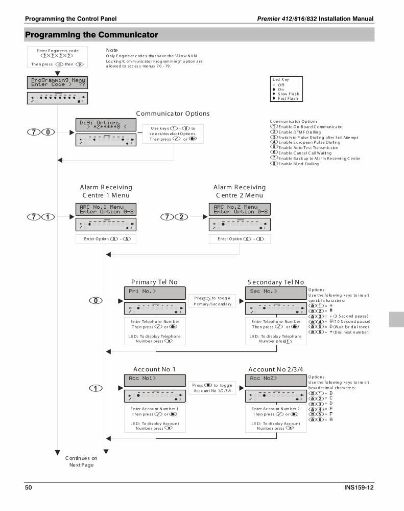
Programming the Control Panel Premier 412/816/832 Installation Manual
50 INS159-12
Programming the Communicator
C ontinue s onNe xt Page
L ed K eyO ffO nS low F la shF ast F la sh
E nte r E n gin ee rs co de
Th e n pre ss the n
Alarm R eceivingC entre 1 Menu
E n ter O ptio n -
C o mm u n ica to r O ptio n s
E n able O n -B o ar d C o mm un ica to r E n able D TM F D ia ll in g S witc h to P ulse D ia ll in g after 3 rd Atte mpt E n able E u ro pea n P u lse D ia ll in g E n able Au to Te st Tran sm is s io n E n able C an ce l C al l W aitin g E n able B a ck up to Alar m R e ce ivin g C en tre E n able B l in d Dial ling
C ommunica tor O ptions
U se k ey s - tose le ct/des elec t O ptio n s .T he n pre ss o r
NoteO n ly E n g in e er c ode s tha t h a ve th e “Allo w N V M Lo c kin g /C om m un ic ato r P ro g ram m in g ” o ptio n a re a llo we d to acc es s me nu s 7 0 - 79 .
Acc ount No 1
E n ter Ac co u nt N um ber 1T he n pre ss o r
L E D : To displa y Acc ou n tN u mbe r press
P r ess to to g g le Acc o un t No 1/2 /3 /4 .
Ac count N o 2/3/4O ptio n sU se th e fo llo win g ke ys to ins ert h exa dec im al ch ara cte rs :
= = = = = =
E n ter Ac co u nt N um ber 2T he n pre ss o r
L E D : To displa y Acc ou n tN u mbe r press
O ptio n sU se th e fo llo win g ke ys to ins ert spe cia l c ha ra cter s :
= = = (3 S ec o nd pau se ) = (1 0 S e co n d pa u se) = (W a it fo r d ia l to ne ) = (D ia l n ext n um ber )
P rima ry Tel No
P r ess to to g g le P rim ary /S ec o nda ry.
S econda ry Tel N o
E n te r Teleph o ne Nu m berT he n pre ss o r
L E D : To displa y Teleph o neN u mbe r press
E n te r Teleph o ne Nu m berT he n pre ss o r
L E D : To displa y Teleph o neN um ber pre ss
Alarm R eceivingC entre 2 Menu
E n ter O ptio n -
3
3
3
3
3
3
3
3

Premier 412/816/832 Installation Manual Programming the Control Panel
INS159-12 51
P r o to co l Ty pes
D isa ble d P u ls e Fo rm a t E xpre ss F or ma t F ast F or ma t/S pe e ch M o du le C on tac t ID
S IA Le vel 2/3 P ag e r Fo rm at Mo bile P h o ne
P rotoc ol Ty pe
E nte r P ro to c ol ty pe - U se to sc rol l typethe n pre ss
L C D :
C ontinue s onNe xt Page
Dia l Attempts
E n te r V alue - .U se to s cro ll valu e
the n pre ss
L C D:
N o teR e por tin g P a rtitio n s ar e o nly u sed by the fo l lo win g pro toc o l types :P u ls e Fo rm a tE xpre ss F or ma tC on tac t IDS IA Le vel 2/3P ag e r Fo rm at
R ep orting P artitions
U se k eys - tose le ct/des elec t O ptio n s .T he n pre ss o r
R epo r ting E ve n ts
R e por t P rio rity Alarm an d Ca n cel E ve nts R e por t Alar m an d Ca n ce l E ve nts O pe n a nd C lo se E ven ts B ypass a n d U n by pass E v en ts M ainte na n ce Alar m E ve nts Ta mpe r Ala rm E v en ts Te st Tran sm is s io n E ven ts R esto re E ven ts
R e por t R e por t R e por t R e por t R e por t R e por t
R eporting E v ents
U se k ey s - tose le ct/des elec t O ptio n s .T he n pre ss
o r
P u ls e F o rm a t O ptio n s
U se 1 90 0H z C arrier U se 4 0 P P S B au d R ate E n able P ar ity U se 2 D igit E ven ts U se 2 30 0H z H an dsh ak e U se 2 30 0H z K iss -O ff U se F as t/S lo w F o rma t
Pulse F orma t O ptions
U se k ey s - tose le ct/des elec t O ptio n s .T he n pre ss
o r
F as t F o rm at R e po rtin g
R e por t C h an ne l 1
R e por t C h an ne l 2R e por t C h an ne l 3R e por t C h an ne l 4R e por t C h an ne l 5R e por t C h an ne l 6R e por t C h an ne l 7
R e por t C h an ne l 8
F a st F orma t R eporting
U se k ey s - tose le ct/des elec t O ptio n s .T he n pre ss
o r
P r o to co l O ptio n s
P ag e r DT MF To ne s = 5 00 mS D isa ble Z o n e R e sto rals
D isa ble S IA M odifier /E na ble S pee ch Mo duleD isa ble S epa rate E ven ts fo r E a ch P arti tio nP ag e r Term in a to r = * ( S tar)S e nd P a ge r Term in a tor Twic e/S IA Te xt
C om s. Ack no wle dg em en t To n e C on n ec t via IP
Protocol O ptions
U se k ey s - tose le ct/des elec t O ptio n s .T he n pre ss
o r
FromPrevious Pa ge
3
3
3
3
3
3
3

Programming the Control Panel Premier 412/816/832 Installation Manual
52 INS159-12
F as t F o rm at R e sto r e C h a nn e ls R e por t R esto re o n Ch an n el 1
R e por t R esto re o n Ch an n el 2 R e por t R esto re o n Ch an n el 3 R e por t R esto re o n Ch an n el 4 R e por t R esto re o n Ch an n el 5 R e por t R esto re o n Ch an n el 6 R e por t R esto re o n Ch an n el 7 R e por t R esto re o n Ch an n el 8
F a st F orma t R esto re C ha nnels
U se k ey s - tose le ct/dese le ct C ha nn e ls .
T he n pr ess o r
FromPrevious Pa ge
F as t F o rm at O pe n /C lo se Ch a n n els R e por t O pe n/C lo se on C ha nn e l 1
R e por t O pe n/C lo se on C ha nn e l 2 R e por t O pe n/C lo se on C ha nn e l 3 R e por t O pe n/C lo se on C ha nn e l 4 R e por t O pe n/C lo se on C ha nn e l 5 R e por t O pe n/C lo se on C ha nn e l 6 R e por t O pe n/C lo se on C ha nn e l 7 R e por t O pe n/C lo se on C ha nn e l 8
Fa st F ormat O pen/C lo se C ha nnels
C a nc el C all Waiting Number
U se k ey s - tose le ct/dese le ct C ha nn e ls .
T he n pr ess o r
E n te r Teleph o ne Nu m berT he n pr ess o r
L E D : To displa y Teleph on eN u mbe r press
3
3
3
Communicator Options The on-board digital communicator/modem has the following options:
Enable On-Board Communicator On: The on-board digital communicator will report system events
to the Alarm Receiving Centre. Off: The communicator will not report system events.
Enable DTMF Dialling On: The on-board digital communicator will dial using DTMF (Dual
Tone Multiple Frequency) format. Off: The communicator will dial using the older pulse format.
Switch to Pulse Dialling After 3rd Attempt On: The communicator will switch to the pulse dialling format after
failed 3rd attempt. Off: The communicator will always dial using DTMF format.
Only applicable if Communicator Option 2 is enabled.
Enable European Pulse Dialling On: The communicator will dial using the European pulse dialling
timing ratios. Off: The communicator will dial using US pulse dialling ratios.
Only applicable if Communicator Option 2 is disabled.
Enable Auto Test Transmission On: The communicator will send a periodic test transmission to
the Alarm Receiving Centre. Off: The communicator will not send test transmissions.
Enable Cancel Call Waiting On: The communicator will dial the Cancel Call Waiting sequence
before dialling the monitoring station.
Off: The communicator will not dial the Cancel Call Waiting sequence.
Enable Backup to Alarm Receiving Centre On: The communicator will always report to Alarm Receiving
Centre 1, then make a backup report to Alarm Receiving Centre 2.
Off: The communicator will initially attempt to report to Alarm Receiving Centre 1. If for any reason the communicator fails after using all its attempts, the communicator will attempt to report to Alarm Receiving Centre 2.
Enable Blind Dialling On: The communicator will NOT look for a dial tone before dialling
the telephone number. Off: The communicator will wait for the dial tone before attempting
to dial out.
ARC 1 Communicator Menu The ARC 1 Communicator Menu has the following options:
Primary and Secondary Telephone Numbers
Account Numbers
Protocol Type
Dial Attempts
Partition Options
Reporting Options
Pulse Format Options
Fast Format Reporting Channels
Protocol Options
Telephone Numbers - Alarm Receiving Centre 1 has a primary and secondary telephone number. The primary number is the number that is dialled first and if programmed the secondary telephone number is a backup number for the primary number. If both numbers are programmed the panel will alternate between them when dialling the alarm receiving centre.

Premier 412/816/832 Installation Manual Programming the Control Panel
INS159-12 53
Each telephone number can be up to 24 digits. When entering the telephone number the following keys can be used:
Press to insert a “*”.
Press to insert a “#”.
Press to insert a “,” (3 second pause).
Press to insert a “W” (10 second pause).
Press to insert a “D” (Wait for dial tone).
Press to insert a “+” (Force dials next number).
Account Numbers - Alarm Receiving Centre 1 has four account numbers. Account No 1 is for partition 1 and is also the global account number. Account numbers 2 - 4 are for partitions 2 - 4. To send events on separate account numbers, you must ensure the “Disable Separate Events for Each Partition” is turned off (see Protocol Options on page 55). The account number can be up to 6 digits. Seperate partition account numbers can be selected by pressing the key. When entering the account number the following keys can be used to insert hexadecimal characters:
Press to insert a “B”.
Press to insert a “C”.
Press to insert a “D”.
Press to insert a “E”.
Press to insert a “F”.
Press to insert a “A”.
Protocol Type - This is the reporting protocol that is used to communicate with Alarm Receiving Centre 1. The following protocols are supported:
Disabled Communication disabled.
Pulse Format The panel will communicate with Alarm Receiving Centre 1 using Pulse Format. See page 62 for details on configuring reporting codes.
Express Format The panel will communicate with Alarm Receiving Centre 1 using Express Format. See page 62 for details on configuring reporting codes.
Fast Format/Speech Module The panel will communicate with Alarm Receiving Centre 1 using Fast Format protocol. If the “Enable Speech Module” option is enabled in the Protocol Options (see page 55) the panel will use the plug-on Speech Module to communicate the alarm information. The Fast Format/Speech channels must be programmed to the required to type, see Program Outputs on page 47.
Contact ID The panel will communicate with Alarm Receiving Centre 1 using Contact ID. The defaults Contact ID codes are shown in the standard defaults worksheets from page 86.
SIA Level 2/3 The panel will communicate with Alarm Receiving Centre 1 using SIA Level 2. If the “Send SIA Text” option is enabled, the panel will communicate using SIA level 3. The defaults SIA codes are shown in defaults worksheets from page 86.
Pager The panel will communicate to a pager. When using the pager option the panel transmits the data to the pager using the following format:
Pager Format = AAAAAA EE
AAAAAA 4 - 6 digit account number
EE Event Code
This code is the same code used for Pulse formats (see page 62)
If for example the account number for the site was programmed as 1234 and zone 8 was violated and caused a burglar alarm, the pager would display 1234 38.
When using the pager option the telephone number will require a pause after it to make it work properly, see Telephone Numbers above.
When using the pager option the pager is normally terminated using either a * or #. This is programmable see Protocol Options on page 55.
The dial attempts when using the pager option should be programmed to 1, see Dial Attempts on page 53.
The panel has no way of confirming if the pager was called successfully which means a “Communication Failure” fault will never be generated.
The panel will only report the event groups that are selected in the Reporting Options, see page 54.
Mobile Phone This protocol can be used to communicate with standard or mobile phones. When an alarm is activated the panel will dial the programmed telephone number and play a number of “bleeps”, which is repeated 10 times, after which the panel will hang-up.
The number of bleeps corresponds to the pulse format code for the selected event, e.g., if the pulse code for zone 4 alarm is programmed as “4” the panel will play 4 “bleeps”. See page 62 for details on configuring reporting codes.
Dial Attempts - This is the number of times the panel will attempt to communicate with Alarm Receiving Centre 1.
The maximum number of repeat dialling attempts is limited to 9. The system will only allow you to enter values between 0 and 9. Setting the value to 0 will disable the communicator for ARC 1.
Partition Options - The Partition Options are described as follows:
Report for Partition 1 On: The system will report events for Partition 1 to Alarm
Receiving Centre 1. Off: The system will not report events for Partition 1.
Report for Partition 2 On: The system will report events for Partition 2 to Alarm
Receiving Centre 1. Off: The system will not report events for Partition 2.

Programming the Control Panel Premier 412/816/832 Installation Manual
54 INS159-12
Report for Partition 3 (Premier 816/832 Only) On: The system will report events for Partition 3 to Alarm
Receiving Centre 1. Off: The system will not report events for Partition 3.
Report for Partition 4 (Premier 816/832 Only) On: The system will report events for Partition 4 to Alarm
Receiving Centre 1. Off: The system will not report events for Partition 4.
Reporting Options - The Reporting Options are described as follows:
Report Priority Alarm and Cancel Events On: Priority alarm and cancel events are reported to ARC1. Off: Priority alarms and cancel events are not reported.
Report Alarm and Cancel Events On: Alarm and cancel events are reported to ARC1. Off: Alarm and cancel events are not reported.
Report Open and Close Events On: Open and close events are reported to ARC1. Off: Open and close events are not reported.
Report Bypass and Unbypass Events On: Bypass and unbypass events are reported to ARC1. Off: Bypass and unbypass events are not reported.
Report Maintenance Alarm Events On: Maintenance alarm events are reported to ARC1. Off: Maintenance alarm events are not reported.
Report Tamper Alarm Events On: Tamper alarm events are reported to ARC1. Off: Tamper alarm events are not reported.
Report Test Transmission Events On: Test transmission events are reported to ARC1. Off: Test transmission events are not reported.
Report Restore Events On: Restore events are reported to ARC1. Off: Restore events are not reported.
Pulse Format Options - If ARC 1 protocol is programmed for “Pulse Format”, the pulse format protocol can be changed using this menu option. The following options are available:
Use 1900Hz Carrier On: Pulse Format carrier frequency is set to 1900Hz. Off: Pulse Format carrier frequency is set to 1800Hz.
Use 40 PPS Baud Rate On: Pulse Format baud rate is set to 40 pulses per second. Off: Pulse Format baud rate is set to 20 pulses per second.
Enable Parity On: Pulse Format uses parity. Off: Pulse Format doesn’t use parity.
Use 2 Digit Events On: Pulse/Express Format uses 2 digits (3 + 2 or 4 + 2). Off: Pulse/Express Format uses 1 digit (3 + 1 or 4 + 1).
Use 2300Hz Handshake On: Pulse Format uses 2300Hz handshake. Off: Pulse Format uses 1400Hz handshake.
Use 2300Hz Kiss-Off Frequency On: Pulse Format uses 2300Hz kiss-off. Off: Pulse Format uses 1400Hz kiss-off.
Use Fast/Slow Format On: Pulse Format uses 10 PPS. Off: Pulse Format uses either 20 or 40 PPS as defined by option 2
(Use 40 PPS Baud Rate).
The table below shows how to configure some of the common protocols:
Protocol Zone Lights
1 2 3 4 5 6 7
Ademco Slow 3x1/4x1 - - - - - -
Ademco Slow 3x2/4x2 - - -
- -
Ademco Fast 3x1/4x1 - - - - - - -
Ademco Fast 3x2/4x2 - - -
- - -
Silent Knight Fast 3x1/4x1
- - - - - -
Silent Knight Fast 3x2/4x2
- -
- - -
FBI (No Parity) 3x1/4x1
- - - - - -
FBI (Parity) 3x1/4x1
-
- - - -
Franklin 3x1/4x1 - - - -
-
Franklin 3x2/4x2 - - -
-
Radionics 3x1/4x1 -
- -
-
Radionics (Parity) 3x1/4x1 -
-
-
Radionics 3x2/4x2 -
-
-
Radionics (Parity) 3x2/4x2 -
-
Sescoa
- - - - - -
Sescoa Super Fast - -
- - - -
= Zone Light On
Fast Format Reporting Channels - This option defines which channels are reported to Alarm Receiving Centre 1 when using the Fast Format communication protocol (see page 53).
Report Fast Format Channel 1 On: Channel 1 is reported. Off: Channel 1 is not reported.
Report Fast Format Channel 2 On: Channel 2 is reported.

Premier 412/816/832 Installation Manual Programming the Control Panel
INS159-12 55
Off: Channel 2 is not reported.
Report Fast Format Channel 3 On: Channel 3 is reported. Off: Channel 3 is not reported.
Report Fast Format Channel 4 On: Channel 4 is reported. Off: Channel 4 is not reported.
Report Fast Format Channel 5 On: Channel 5 is reported. Off: Channel 5 is not reported.
Report Fast Format Channel 6 On: Channel 6 is reported. Off: Channel 6 is not reported.
Report Fast Format Channel 7 On: Channel 7 is reported. Off: Channel 7 is not reported.
Report Fast Format Channel 8 On: Channel 8 is reported. Off: Channel 8 is not reported.
The channel must also be programmed to report an event, see “Program Outputs” on page 45.
Protocol Options - This menu option allows you to alter the operation of certain protocol types. The Protocol Options are described as follows:
Disable SIA Modifier Block/Enable Speech Module On: When using SIA protocol, the area/partition modifier data
block (ri) is not transmitted. When using Fast Format protocol the Speech Module is enabled.
Off: When using SIA protocol, the area/partition modifier data block (ri) is transmitted. When using Fast Format protocol the Speech Module is disabled.
Disable Separate Events for Each Partition On: The panel will communicate as follows:
• If the event occurs in single partition, the panel will report the event using the appropriate account number for the partition.
• If the event occurs in multiple partitions, the panel will report the event using the appropriate account number for the lowest partition, e.g., if the event occurs in partitions 2, 3 and 4, the panel will report the event for partition 2.
• If the account number is not programmed for partitions 2, 3 and 4, the global (partition 1) account number is used.
Off: The panel will communicate as follows:
• If the event occurs in single partition, the panel will report the event using the appropriate account number for the partition.
• If the event occurs in multiple partitions, the panel will report a separate event for each partition using the appropriate account numbers. E.g., if the event occurs in partitions 1 and 3, the panel will report the event for partition 1 using the account number for partition 1, then
it will report the event for partition 2 using the account number for partition 2.
• If the account number is not programmed for partitions 2, 3 and 4, the global (partition 1) account number is used.
Pager Terminator = * (Star) On: When using the pager format, the panel transmits a * (star) to
terminate the pager call. Off: When using the pager format, the panel transmits a # (hash)
to terminate the pager call.
Send Pager Terminator Twice/SIA Text On: When using the pager format, the panel transmits the pager
terminator (* or #) twice to terminate the pager call. If SIA protocol is enabled, the panel will send zone/user text for relevant events (SIA level 3).
Off: When using the pager format, the panel transmits the pager terminator (* or #) once to terminate the pager call. If SIA protocol is enabled, the panel does not send zone/user text for relevant events (SIA level 2).
Pager DTMF Tones = 500mS On: When using the pager format, the panel transmits the pager
DTMF tones with an on time of 500mS. Off: When using the pager format, the panel transmits the pager
DTMF tones with an on time of 80mS.
Disable Zone Restorals On: Zone restore events are not sent to the Alarm Receiving
Centre (even if Report Restore Events are enabled, see page 54).
Off: Zone restore events are sent to the Alarm Receiving Centre 1 (providing Report Restore Events are enabled, see page 54).
Communication Acknowledgment Tone On: After a successful communication with the alarm receiving
centre the keypads and panel speaker will generate an acknowledgment tone.
Off: After a successful communication the system will remain silent.
Send via IP On: Alarm events are sent to the ARC via the ComIP module
(TCP/IP). Only Fast Format, Contact ID and SIA protocols are supported with this option.
Off: Alarm events are not sent via the ComIP module.
ARC 2 Communicator Options This option allows the on-board communicator to be configured for Alarm Receiving Centre 2. The same options are available as for the ARC 1 communicator options (see above).
Fast Format Restore Channels If either ARC 1 or ARC 2 protocols are programmed as “Fast Format (UK)”, the channels that report a restore event to the Alarm Receiving Centre may be selected.
Report Restore on Channel 1 On: Restore reported on channel 1. Off: Restore not reported on channel 1.
Report Restore on Channel 2 On: Restore reported on channel 2. Off: Restore not reported on channel 2.
Report Restore on Channel 3 On: Restore reported on channel 3. Off: Restore not reported on channel 3.

Programming the Control Panel Premier 412/816/832 Installation Manual
56 INS159-12
Report Restore on Channel 4 On: Restore reported on channel 4. Off: Restore not reported on channel 4.
Report Restore on Channel 5 On: Restore reported on channel 5. Off: Restore not reported on channel 5.
Report Restore on Channel 6 On: Restore reported on channel 6. Off: Restore not reported on channel 6.
Report Restore on Channel 7 On: Restore reported on channel 7. Off: Restore not reported on channel 7.
Report Restore on Channel 8 On: Restore reported on channel 8. Off: Restore not reported on channel 8.
The channel must also be programmed to report an event, see “Program Outputs” on page 45.
The channel must also be programmed to report to the ARC, see “Fast Format Reporting Channels” on page 54.
Fast Format Open/Close Channels If either ARC 1 or ARC 2 protocols are programmed as “Fast Format (UK)”, the channels that report an Open/Close event to the Alarm Receiving Centre may be selected.
Report Open/Close on Channel 1 On: Open/Close reported on channel 1. Off: Open/Close not reported on channel 1.
Report Open/Close on Channel 2 On: Open/Close reported on channel 2. Off: Open/Close not reported on channel 2.
Report Open/Close on Channel 3 On: Open/Close reported on channel 3. Off: Open/Close not reported on channel 3.
Report Open/Close on Channel 4 On: Open/Close reported on channel 4. Off: Open/Close not reported on channel 4.
Report Open/Close on Channel 5 On: Open/Close reported on channel 5. Off: Open/Close not reported on channel 5.
Report Open/Close on Channel 6 On: Open/Close reported on channel 6. Off: Open/Close not reported on channel 6.
Report Open/Close on Channel 7 On: Open/Close reported on channel 7. Off: Open/Close not reported on channel 7.
Report Open/Close on Channel 8 On: Open/Close reported on channel 8. Off: Open/Close not reported on channel 8.
The channel must also be programmed to report an event, see Program Outputs on page 45.
The channel must also be programmed to report to the ARC, see “Fast Format Reporting Channels” on page 54.
Cancel Call Waiting Sequence This is the number that the panel dials to disable Call Waiting. The number can be up to 24 digits. The Cancel Call Waiting option must also be enabled, see Communicator Options on page 52.

Premier 412/816/832 Installation Manual Programming the Control Panel
INS159-12 57
Programming Check List The table below provides a checklist of what options require programming for each of the protocols supported:
Protocol
0 -
Tele
pho
ne N
o
1 -
Acc
oun
t No
2 -
Pro
toco
l Typ
e
3 -
Dia
l Att
emp
ts
4 -
Par
titio
n O
ptio
ns
5 -
Rep
ort
ing
Op
tions
6 -
Pul
se F
orm
at O
ptio
ns
7 -
Fast
Fo
rmat
Cha
nnel
s
8 -
Pro
toco
l Op
tions
73 -
Fas
t Fo
rmat
Res
tore
Cha
nnel
s
74 -
Fas
t Fo
rmat
Op
en/C
lose
Cha
nnel
s
Notes
Pulse Format
1 2 3
1. Program to type 1. 2. Use table on page 54. 3. Set option 6 as required.
Express Format
1 2 3
1. Program to type 2.
2. Enable option 4 if 2 digit format is required. 3. Set option 6 as required.
Fast Format 1
2
3
4
1. Program to type 3. 2. Select channels that are required to report. Also program the channels for the relevant type, see page 47. 3. Select channels that require a restore to be reported. 4. Select channels that require to report Open/Close.
Speech Module
1
2
3
1. Program to type 3. 2. Select channels 1 and/or 2,3 & 4. Also program the channels for the relevant type, see page 47. 3. Enable option 1.
Contact ID 1
2
1. Program to type 4.
2. Set options 2 and 6 as required.
SIA Level 2
1
2
1. Program to type 5.
2. Set options 1, 2 and 6 as required.
SIA Level 3
1
2
1. Program to type 5.
2. Set options 1, 2 and 6 as required. Enable option 4.
Pager
1
2
1. Program to type 6.
2. Set options 3, 4, 5 and 6 as required.
Mobile Phone 1
2
1. Program to type 7.
2. Set option 6 as required.

Programming the Control Panel Premier 412/816/832 Installation Manual
58 INS159-12
Programming Download Options
L ed K eyO ffO nS low F la shF ast F la sh
E nte r E n gin ee rs co de
Th e n pre ss the n
Downloa d Menu
E n ter O ptio n -
D o wn lo a d O ptio n s
E n able Atten ded D own lo a d E n able U na tten ded Ca ll B a ck E n able 2 -Ca ll Ans we r P h on e D e fe at R e strict Do wnlo ad wh e n Arm e d D own lo a d wh en P art Arm ed
D isc on n ec t Te le pho n e L in e
Downloa d O ptions
U se k ey s - tose le ct/des elec t O ptio n s .T he n pre ss o r
C a ll-B ac k N umb er
UD L P as sc ode
C a ll-B a c k Attempts
R ing C ount
E n te r V alue - .U se to s cro ll valu ethe n pre ss .
L CD :
E n te r V alue - .U se to s cro ll valu ethe n pre ss .
L CD :
NoteO n ly E n g in e er c ode s tha t h a ve th e “Allo w N V M Lo c kin g /C om m un ic ato r P ro g ram m in g ” o ptio n a re a llo we d to acc es s me nu s 7 0 - 79 .
E n te r Teleph o ne Nu m berT he n pre ss o r
L E D : To displa y Teleph o neN u mbe r press
E n ter P a ssc odeT he n pre ss o r
L E D : To displa y Teleph o neN u mbe r press
C ontinue s onNe xt Page
3
3
3
3
3
3
3

Premier 412/816/832 Installation Manual Programming the Control Panel
INS159-12 59
D ev ice Type s
P C -Co m /US B -C om R a dio P lu s Ino vo n ic s R adio C om IP M o du le
W ebW ay O ne /E m izo n M odu le C hiro n M odu le
C om 1 D evic e Typ e
E n te r De vice type - Use to scr ol l typethe n pre ss
L C D :
N o teT he Co m IP G a te way a ddress M US T be e n te re d a s a 1 2 d ig it s equ en ce , e . g . I f th e G a te way a ddress is 1 92 .1 6 8. 0. 1 , th en it sh o uld be en tere d as :1 92 1 6 8 00 0 0 01
C o mIP G ateway Add res s
C omIP S ubnet Mas k
E n ter S u bne t Mas k valu e - .
FromPrevious Pa ge
C omIP Ad dres s & PortE n te r IP A ddre ss & P o rt No
T h en pr ess o r
L E D : To displa y IP Addre ss &P o rt No pres s
N o teT he Co m IP a ddr ess a n d po rt nu mbe r MU S T be e nte red as a 17 dig it se qu e nc e, e. g . If the IP a ddre ss is 19 2. 1 68 .0 . 10 an d th e po rt nu m ber 9 80 , th en it sho u ld be e nte re d a s :1 92 1 6 8 00 0 0 10 00 9 80
E n ter G a teway a ddres sT h en pr ess o r
LE D: To displa y G ate wayaddres s press
C om 2 D evic e Typ e
E n te r De vice type - Use to scr ol l typethe n pre ss
L C D :
D ev ice Type s
P C -Co m /US B -C om R a dio P lu s Ino vo n ic s R adio C om IP M o du le W ebW ay O ne /E m izo n M odu le C hiro n M odu le
E n ter O ptio n -
Use to scr ol l typethe n pre ss
L C D :
C hiron Iris S etup C h ir o n Da ta
Ac ces s P T N am e U ser N am e P as sword
3
3
3
3
3
3

Programming the Control Panel Premier 412/816/832 Installation Manual
60 INS159-12
Download Menu The Download Menu has the following options:
Download Options
Download Telephone Number
UDL Passcode
Call Back Attempts
Ring Count
Com1 Device Type
ComIP Address & Port
ComIP Gateway address
ComIP Subnet Mask
Com 2 Device Type
Chiron Data Setup
Download Options - The system has the following Download options:
Enable Attended Download On: The system will only allow download access if a user has
authorised downloading. Off: The system will allow unattended download access.
Enable Unattended Call Back On: The system will call back the remote computer before the
system can be downloaded. Off: Call back is not required.
Enable 2-Call Answer Phone Defeat On: The panel will answer incoming calls as follows:
• In order to “prime” the panel one or more rings must be detected, but the panel must not detect more than the ring count. If the panel detects more than the ring count the panel will not “prime” itself.
• The panel will remain in primed state for 60 seconds.
• When the panel is primed the next incoming call is answered immediately.
Off: The panel will answer incoming calls after the specified “Download Ring Count”, see below.
Restrict Download when Armed On: Download access is restricted when the system is armed (see
option 5 below). Off: The panel can be downloaded at any time.
Download when Part Armed If option 4 above is enabled, then downloading is restricted as follows:
On: The panel will allow download access if system is part armed (one or more partitions disarmed).
Off: The panel will only allow download access when all partitions are disarmed.
Disconnect Telephone Line If this option is enabled, the standard T and R connections cannot be used instead the telephone line must be connected to terminals T1 and R1. This configuration provides additional lightning protection as the telephone line is isolated most of the time and is
only switched in when the panel is required to transmit an alarm or to test the status of the telephone line. If this option is used then it is NOT possible to use the upload/download feature unless the user enables “Remote Access” see page 69. The operation is as follows:
On: The telephone line is disconnected from panel during normal operation and is only switched in when the panel is required to send an alarm event or test the line (tested every hour).
Off: The telephone line is continuously connected and operates as normal.
&(down) or &(up) Polling IP Address & Port Number This is the polling IP Address and Port number of the alarm Receiving Centre. The IP address and port number MUST be entered as a 17 digit sequence, e.g. if the IP address is 192.168.0.10 and the port number 980, then it should be entered as: 19216800001000980. Values entered here are not used to set up the Chiron IRIS Module, (The Chiron IRIS module’s Polling IP Address is taken from the first 12 digits of the Primary Telephone Number and its Account Number is that of Partition 1).
Call Back Number - This is the telephone number that is used to dial the remote downloading computer when the system has been configured to use Unattended Call Back, see Download Options.
UDL Passcode - When the remote downloading computer dials into the system, the control panel compares the Security code sent by the computer with Security code stored in the control panel. If the Security codes match, access to the control panel is granted, otherwise access is denied.
The security programmed in this option MUST also be programmed in the customer account on the remote downloading computer. The Security code can be up to 8 characters.
Download Dial Attempts - If the “Enable Unattended Call Back” feature is enabled, (see Download Options), this option controls the number of times the panel will attempt to call back the remote downloading computer.
The maximum number of repeat dialling attempts is limited to 9. The system will only allow you to enter values between 0 and 9. Setting the value to 0 will disable the modem from dialling out.
Ring Count - This counter controls the number of rings required in order for the on-board modem to answer the incoming call. If the “Ring Count” is set to 0 the panel will not answer any incoming calls.
Com1 Device Type - This option allows you to specify which module is connected to communication port Com1.The control panel will accept the following modules:
PC-Com RadioPlus Inovonics Radio ComIP WebWayOne/Emizon Module Chiron Module

Premier 412/816/832 Installation Manual Programming the Control Panel
INS159-12 61
IP Address & Port - This option allows you to assign a local IP address and port number to a module connected to a Com Port (e.g. ComIP or Chiron IRIS). The IP address and port number MUST be entered as a 17 digit sequence, e.g. If the IP address is 192.168.0.10 and the port number 980, then it should be entered as: 19216800001000980. If an IP module (WebWayOne, Chiron IRIS, etc) is fitted its IP address and port must also enter via the Polling IP address and port number.
Note for the Chiron IRIS module entry of only the12 digit IP Address results in the port number being set to its default, 10001.
ComIP Gateway Address - This option allows you to assign a Gateway IP address to the ComIP module (if fitted). The Gateway IP address MUST be entered as a 12 digit sequence, e.g. If the Gateway IP address is 192.168.0.1, then it should be entered as: 192 168 000 001.
ComIP Subnet Mask - This option allows you to assign a Subnet Mask to the ComIP module (if fitted). The Subnet Mask is entered as a decimal value of 001 through to 024. Each decimal value generates the following Subnet Masks used by the ComIP module:
Value Subnet Mask Value Subnet Mask
001 255.255.255.254 013 255.255.224.0
002 255.255.255.252 014 255.255.192.0
003 255.255.255.248 015 255.255.128.0
004 255.255.255.240 016 255.255.0.0
005 255.255.255.224 017 255.254.0.0
006 255.255.255.192 018 255.252.0.0
007 255.255.255.128 019 255.248.0.0
008 255.255.255.0 020 255.240.0.0
009 255.255.254.0 021 255.224.0.0
010 255.255.252.0 022 255.192.0.0
011 255.255.248.0 023 255.128.0.0
012 255.255.240.0 024 255.0.0.0
Com2 Device Type - This option allows you to specify which module is connected to communication port Com2. See Com1 Device Type above for a list of supported devices.
Chiron Iris Data Setup - This menu option has three submenus to allow programming of the Chiron Iris module data. The value of each parameter can be viewed by pressing the key or its value can be edited by pressing the key. A maximum of 30 characters for the Access Point Name and 32 Characters for User Name and Password can be entered. Text is programmed in a similar way to mobile phones. Characters are selected by pressing the corresponding key the appropriate number of times (to select a character on the same key, press the key to move the cursor along). For details on entering text, see page 22.
--
Access Point Name This is the GPRS Access Point Name. It’s value can be viewed by pressing the key or its value can be edited by pressing the key. A maximum of 30 characters can be entered. Text is programmed in a similar way to mobile phones. Characters are selected by pressing the corresponding key the appropriate number of times (to select a character on the same key, press the key to move the cursor along). For details on entering text, see page 22.
--
User Name This is the GPRS Access Point Name. It’s value can be viewed by pressing the key or its value can be edited by pressing the key. A maximum of 32 characters can be entered. Text is programmed in a similar way to mobile phones. Characters are selected by pressing the corresponding key the appropriate number of times (to select a character on the same key, press the key to move the cursor along). For details on entering text, see page 22.
--
Password This is the GPRS Access Point Name. It’s value can be viewed by pressing the key or its value can be edited by pressing the key. A maximum of 32 characters can be entered. Text is programmed in a similar way to mobile phones. Characters are selected by pressing the corresponding key the appropriate number of times (to select a character on the same key, press the key to move the cursor along). For details on entering text, see page 22.

Programming the Control Panel Premier 412/816/832 Installation Manual
62 INS159-12
Programming Reporting Codes
E v en t C o de s
- N on e - 1 - 2 - 3 - 4 - 5 - 6 - 7 - 8 - 9 - A (0 ) - B - C - D - E - F
Zone Ala rm/R es tore C odes
E n ter E v en t N o : -
E nte r 1 eve nt co des t .E n ter 2 e ven t co de .n d
Zone B ypa ss /Unby pas s C o des
Non Zone Ala rm/R es tore C odes
E nte r 1 eve n t c ode s t .
E n ter 2 e ven t co de .n d
E nte r 1 eve n t c ode s t .E n ter 2 e ven t co de .n d
L ed K eyO ffO nS low F la shF ast F la sh
E nte r E n gin ee rs co de
Th e n pre ss the n
E n ter E v en t N o : -
E n ter E v en t N o : -
N o E v e nt T ype0 0 Z o n e 01 Ala rm0 1 Z o n e 01 R e stor e0 2 Z o n e 02 Ala rm0 3 Z o n e 02 R e stor e0 4 Z o n e 03 Ala rm0 5 Z o n e 03 R e stor e0 6 Z o n e 04 Ala rm0 7 Z o n e 04 R e stor e0 8 Z o n e 05 Ala rm0 9 Z o n e 05 R e stor e1 0 Z o n e 06 Ala rm1 1 Z o n e 06 R e stor e1 2 Z o n e 07 Ala rm1 3 Z o n e 07 R e stor e1 4 Z o n e 08 Ala rm1 5 Z o n e 08 R e stor e
16 Z on e 0 9 A la rm17 Z on e 0 9 R esto re18 Z on e 1 0 A la rm19 Z on e 1 0 R esto re20 Z on e 1 1 A la rm21 Z on e 1 1 R esto re22 Z on e 1 2 A la rm23 Z on e 1 2 R esto re24 Z on e 1 3 A la rm25 Z on e 1 3 R esto re26 Z on e 1 4 A la rm27 Z on e 1 4 R esto re28 Z on e 1 5 A la rm29 Z on e 1 5 R esto re30 Z on e 1 6 A la rm31 Z on e 1 6 R esto re
No E ve n t Ty pe
Zone A larm/R es tore E ve nt Numbe rs
N o E v e nt T ype0 0 Z o n e 01 B ypa ss0 1 Z o n e 01 Un bypa ss0 2 Z o n e 02 B ypa ss0 3 Z o n e 02 Un bypa ss0 4 Z o n e 03 B ypa ss0 5 Z o n e 03 Un bypa ss0 6 Z o n e 04 B ypa ss0 7 Z o n e 04 Un bypa ss0 8 Z o n e 05 B ypa ss0 9 Z o n e 05 Un bypa ss1 0 Z o n e 06 B ypa ss1 1 Z o n e 06 Un bypa ss1 2 Z o n e 07 B ypa ss1 3 Z o n e 07 Un bypa ss1 4 Z o n e 08 B ypa ss1 5 Z o n e 08 Un bypa ss
1 6 Zo n e 0 9 B y pass1 7 Zo n e 0 9 U nby pa ss1 8 Zo n e 1 0 B y pass1 9 Zo n e 1 0 U nby pa ss2 0 Zo n e 1 1 B y pass2 1 Zo n e 1 1 U nby pa ss2 2 Zo n e 1 2 B y pass2 3 Zo n e 1 2 U nby pa ss2 4 Zo n e 1 3 B y pass2 5 Zo n e 1 3 U nby pa ss2 6 Zo n e 1 4 B y pass2 7 Zo n e 1 4 U nby pa ss2 8 Zo n e 1 5 B y pass2 9 Zo n e 1 5 U nby pa ss3 0 Zo n e 1 6 B y pass3 1 Zo n e 1 6 U nby pa ss
N o E ve n t Type
Zone B ypa ss/Unbypa ss E ve nt Numbe rs
NoteO n ly E n g in e er c ode s tha t h a ve th e “Allo w N V M Lo c kin g /C om m un ic ato r P ro g ram m in g ” o ptio n a re a llo we d to acc es s me nu s 7 0 - 79 .
3
3
3
3
3
3
3
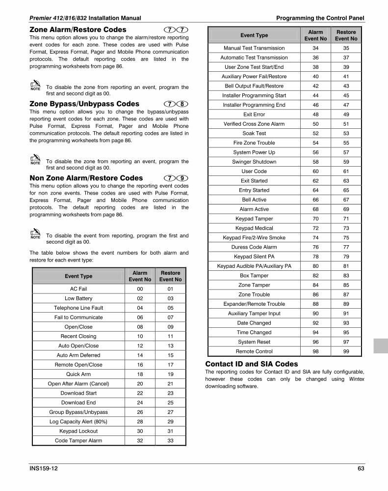
Premier 412/816/832 Installation Manual Programming the Control Panel
INS159-12 63
Zone Alarm/Restore Codes This menu option allows you to change the alarm/restore reporting event codes for each zone. These codes are used with Pulse Format, Express Format, Pager and Mobile Phone communication protocols. The default reporting codes are listed in the programming worksheets from page 86.
To disable the zone from reporting an event, program the first and second digit as 00.
Zone Bypass/Unbypass Codes This menu option allows you to change the bypass/unbypass reporting event codes for each zone. These codes are used with Pulse Format, Express Format, Pager and Mobile Phone communication protocols. The default reporting codes are listed in the programming worksheets from page 86.
To disable the zone from reporting an event, program the first and second digit as 00.
Non Zone Alarm/Restore Codes This menu option allows you to change the reporting event codes for non zone events. These codes are used with Pulse Format, Express Format, Pager and Mobile Phone communication protocols. The default reporting codes are listed in the programming worksheets from page 86.
To disable the event from reporting, program the first and second digit as 00.
The table below shows the event numbers for both alarm and restore for each event type:
Event Type Alarm
Event No Restore
Event No
AC Fail 00 01
Low Battery 02 03
Telephone Line Fault 04 05
Fail to Communicate 06 07
Open/Close 08 09
Recent Closing 10 11
Auto Open/Close 12 13
Auto Arm Deferred 14 15
Remote Open/Close 16 17
Quick Arm 18 19
Open After Alarm (Cancel) 20 21
Download Start 22 23
Download End 24 25
Group Bypass/Unbypass 26 27
Log Capacity Alert (80%) 28 29
Keypad Lockout 30 31
Code Tamper Alarm 32 33
Event Type Alarm Event No
Restore Event No
Manual Test Transmission 34 35
Automatic Test Transmission 36 37
User Zone Test Start/End 38 39
Auxiliary Power Fail/Restore 40 41
Bell Output Fault/Restore 42 43
Installer Programming Start 44 45
Installer Programming End 46 47
Exit Error 48 49
Verified Cross Zone Alarm 50 51
Soak Test 52 53
Fire Zone Trouble 54 55
System Power Up 56 57
Swinger Shutdown 58 59
User Code 60 61
Exit Started 62 63
Entry Started 64 65
Bell Active 66 67
Alarm Active 68 69
Keypad Tamper 70 71
Keypad Medical 72 73
Keypad Fire/2-Wire Smoke 74 75
Duress Code Alarm 76 77
Keypad Silent PA 78 79
Keypad Audible PA/Auxiliary PA 80 81
Box Tamper 82 83
Zone Tamper 84 85
Zone Trouble 86 87
Expander/Remote Trouble 88 89
Auxiliary Tamper Input 90 91
Date Changed 92 93
Time Changed 94 95
System Reset 96 97
Remote Control 98 99
Contact ID and SIA Codes The reporting codes for Contact ID and SIA are fully configurable, however these codes can only be changed using Wintex downloading software.

Programming the Control Panel Premier 412/816/832 Installation Manual
64 INS159-12
Programming Users
L ed K eyO ffO nS low F la shF ast F la sh
E nte r E n gin ee rs co de
Th e n pre ss the n
C ontinue s onNe xt Page
P rogram User
User Op tio ns 1
E n ter U se r N u mbe r.
U se k ey s - tose le ct/des elec t O ptio n s .T he n pr ess o r
U se r O ptio n s 1
E n able fo r P a rtition 1 Al lo w Ar ming Al lo w B ypas s in g Al lo w D is arm in g Al lo w U se r Fu n ctio n s
E n able fo r P a rtition 2E n able fo r P a rtition 3 ( )E n able fo r P a rtition 4 ( )
P re mie r 8 1 6/8 32P re mie r 8 1 6/8 32
U se r O ptio n s 2
E n able O n e T im e U se Ac ce ss C ode T im e Lo c k Co de with Co n tro l T im er 1 E n able O pen R e por tin g E n able C lo se R epo rtin g E n able U ser a s Du re ss C o de Ac tivate Do o r S trik e O u tpu t Al lo w G lo ba l B e l l/S o u nde r S ilen ce
D isa ble R em o te Acc es s
User Op tio ns 2
U se k ey s - tose le ct/des elec t O ptio n s .T he n pr ess o r
E n ter U se r N u mbe r.
U se r O ptio n s 3
Al lo w E ng ine er C o de P ro g ram m in g Al lo w N V M L oc king Al lo w E ng ine er P ro g ra mm in g Al lo w Te st Ca ll Tran sm is s io n Al lo w Alar m/F au lt Ac kn owledg e me nt Al lo w U se r P ro g ram min g Al lo w U se r Co de P r og ra mm in g Lo c al P a rtition Acc es s O nly
User Op tio ns 3
U se k ey s - tose le ct/des elec t O ptio n s .T he n pr ess o r
E n ter U se r N u mbe r.
E n ter U se r N u mbe r.
E nte r Co de
P r ess o r if co de isle ss tha n 6 d ig its .
R e-e n te r N ew Co de
A
R etu rn to po in t A
3
3
3
3
3
3
3
3
3
3

Premier 412/816/832 Installation Manual Programming the Control Panel
INS159-12 65
FromPrevious Pa ge
Te xt E ditin g K e ys
. , ? ! 1 @ ” - & a b c 2 A B C d e f 3 D E F g h I 4 G H I j k l 5 J K L m n o 7 M N O p q r s 7 P Q R S t u v 8 T U V
w x y z 9 W X Y Z S pac e 0 , # * Mo ve Le ft/R ig ht B ac kspa ce ( de le te)
U se ke ys to e nte r/e dit te xt.T he n pre ss to ac ce pt.
U se to se le ct Us er.
P res s
to edit te xt.
Us er Text
D efa ult ALL Us ers
T he "Lo ad D efau lts " pins ( J P 6 ) be link ed to ge th er befo re s elec tin g th is o ptio n .
After se lecting th is o ptio n, U ser 0 1( Ma ster) i sreve rted to 5 67 8 a n d U se rs 02 to 3 1/6 3 a re delete d.
M U S T
D elete U ser
E n ter U se r N u mbe r.
P r ess
E n ter U se r N u mbe r
.
E nte r Co de
P r ess o r if co de isle ss tha n 6 d ig its .
R e-e n te r N ew Co de
P rogram S ta nd ard Us ers
Ass ign R adio F ob
E n ter U se r N u mbe r th en .
P re ss bu tto n on the Fo b( Disar m for )R adio P lus
3
3
3
3
3
3
3

Programming the Control Panel Premier 412/816/832 Installation Manual
66 INS159-12
Program User The Program User option allows the engineer to assign new users for the alarm system. The number of users (including the engineer) that are available is as follows:
• Premier 412 - 32 Users
• Premier 816 - 32 Users
• Premier 832 - 64 Users
User 00 is the Engineer and can only be accessed by the engineer code. User 01 is the Master User which has a default code of 5678. Neither of these two users can be deleted from the system.
Each user is assigned the following attributes:
• Access Code This is a unique 4, 5 or 6 digit code that is assigned to the user. The system will allow a mixture of different length Access codes. The Access code must be entered at a keypad before the user can operate the alarm system.
• User Options 1 See User Options 1 on page 66 for details.
• User Options 2 See User Options 2 on page 66 for details.
• User Options 3 See User Options 3 on page 67 for details.
• User Text (LCD Only) See User Text on page 67 for details.
When using an LED keypad it is possible to view the next available user by pressing the key before entering the two digit user number. This will cause the next available user to be indicated using the top row of status lights.
User Options 1 User Options 1 can be enabled or disabled for a selected user so that the level of access to the system may be altered. The following options are available:
Enable for Partition 1 On: The user can access Partition 1. Off: The user cannot access Partition 1.
Enable for Partition 2 On: The user can access Partition 2. Off: The user cannot access Partition 2.
Enable for Partition 3 (Premier 816/832 Only) On: The user can access Partition 3. Off: The user cannot access Partition 3.
Enable for Partition 4 (Premier 816/832 Only) On: The user can access Partition 4. Off: The user cannot access Partition 4.
Allow Arming On: The user can arm the partitions they have been given access
to. Off: The user cannot arm any partitions.
Allow Bypassing On: The user can bypass zones in partitions they have been given
access to. Off: The user cannot bypass zones.
Allow Disarming On: The user can disarm the partitions they have been given
access to. Off: The user cannot disarm any partitions.
The Engineer code (User 0) can only disarm the system, if the system was armed with the Engineer code.
Allow User Functions On: The user can access the following user functions:
• Reset • View Alarm Log • View Service Faults • Enable Chime • Change Own Code
Off: The user cannot access the above user functions.
User Options 2 User Options 2 can be enabled or disabled for a selected user so that the level of access to the system may be altered. The following options are available:
Enable One Time Use Access Code On: The Access code can only be used once to arm and disarm
the system. After the Access code has been used to arm the system it is automatically deleted.
Off: The Access code behaves normally.
Time Lock Code with Control Timer 1 On: When Control Timer 1 is on, the Access code will not be
accepted by the system. When Control Timer 1 is off, the Access code will be accepted by the system. For information on programming Control Timers, see page 36.
Off: The Access code will be accepted at all times.
Enable Open Reporting On: The system will report an ‘Open’ condition to the alarm
receiving centre when the Access code is used to disarm one or more partitions.
Off: The system will not report an ‘Open’ status.
The panel will always send an open signal after an alarm even if this option is disabled.
Enable Close Reporting On: The system will report a ‘Close’ condition to the monitoring
station when the Access code is used to arm one or more partitions.
Off: The system will not report a ‘Close’ condition.
Enable User as Duress Code On: The Access code will report a ‘Duress’ condition to the
monitoring station when the Access code is used. Off: The Access code behaves normally.
Activate Door Strike Output On: When a user Access code is entered, the output type “Door
Strike” (see page 49) is activated for 2 seconds. Off: The user Access code will not activate the “Door Strike”
output.
Allow Global Bell/Sounder Silence On: This option allows users to silence the bell and internal
sounder for any partition, even if the user is not assigned to

Premier 412/816/832 Installation Manual Programming the Control Panel
INS159-12 67
the partition that is in alarm. The user cannot disarm or reset the partition if they are not assigned to it.
Off: The user can only silence alarms for partitions that are assigned to their code.
Disable Remote Access On: The touch-tone remote control feature is disabled for the
selected user. Off: The touch-tone remote control feature is enabled for the
selected user.
User Options 3 User Options 3 can be enabled or disabled for a selected user so that the level of access to the system may be altered. The following options are available:
Allow Engineer Code Programming On: The Access code can access User 00 (Engineer) in the
Program New Users menu (menu 80). Off: The Access code cannot access user 00 in the Program New
Users menu.
Allow NVM Locking/Communicator Programming On: The Access code is allowed to lock/unlock the NVM
(providing “Allow Engineer Programming” is enabled). Once the NVM is locked the “Load Defaults” jumper pins on the main control panel are disabled, thus preventing the panel from being defaulted. The Access code is also allowed to access the communicator programming menus 70 - 79.
Off: The Access code cannot lock/unlock the NVM or access communicator programming menus 70 - 79.
Allow Engineer Programming On: The Access code can access the Engineer programming
menus. Off: The Access code cannot access the Engineer programming
menus.
Allow Test Call Transmission On: The Access code can perform a test transmission to the
monitoring station (menu 92, see page 69). Off: The Access code cannot perform a test transmission.
Allow Alarm/Fault Acknowledgement On: The Access code can be used to acknowledge and reset
alarms and service faults. A user with this option can disarm the system after an alarm, even if the user does not have the "Allow Disarming" option.
Off: The Access code cannot be used to acknowledge and reset alarms and service faults.
Allow User Programming On: The Access code can access the user program menus (menu
90 - 98). Off: The Access code cannot access the user program menus.
Allow User Code Programming On: The Access code can access users 01 to 31 in the User
programming menus (menus 80 - 85). Off: The Access code cannot access user 01 to 31 in the User
programming menus.
Local Partition Access Only On: The Access code can only be used to arm and disarm the
partitions that are assigned to the remote keypad. For example, if the user is assigned to all four partitions and they use a remote keypad that is only assigned to partition 1, they will only be permitted to arm and disarm partition 1 at that particular remote keypad.
Off: The Access code can be used at any remote keypad (Global access).
User Text (LCD Only) If the system is fitted with a LCD remote keypad you can assign up to 8 characters of text to each user. This text is used when viewing the system Event Log, see page 77. User text is programmed in a similar way to mobile phones. Characters are selected by pressing the corresponding key the appropriate number of times (to select a character on the same key, press to move the cursor along). For details on entering text, see page 22.
Program Standard Users This menu option allows you to add “Standard” users to the system. The user will automatically be assigned the following options:
User Options 1: Partition 1 Access
Allow Arming
Allow Bypassing
Allow Disarming
Allow User Functions
User Options 2: Enable Open Reporting
Enable Close Reporting
Allow Global Bell/Sounder Silence
User Options 3: Allow Alarm/Fault Acknowledgement
Default ALL Users This menu option allows you to default all Users to their factory default settings. Before selecting this menu option you MUST link out the “Load Defaults” pins (JP6) on the control panel PCB, see page 8. After selecting this option, User 01(Master) is reverted to 5678 and Users 02 onwards are deleted.

Programming the Control Panel Premier 412/816/832 Installation Manual
68 INS159-12
System Tests & Utilities
L ed K eyO ffO nS low F la shF ast F la sh
E nte r E n gin ee rs co de
Th e n pre ss the n
C ontinue s onNe xt Page
Walk Test
Activ ate Z o n es
P res s to clea r te ste dzon e s fr om display
To p l in e sc ro lls ac tive z on e sB o ttom line scr ol ls te sted zo ne s
Z o ne ligh t flas hin g = zo n e a ctiv eZ o ne ligh t o n = zo n e tes ted
Test S pea kers & O utputs
E n ter Te st N u mbe r -
S y ste m Tes ts
Tes t S pe ak ers Tes t B e lls Tes t S tro be s Tes t O u tputs
Tes t L CD Displa y
P res s to re set tes t
E na ble R emote/E ngineer Acc ess
S tart C all B ac k
Te st C a ll S ta tu s L C D L E DW aitin g fo r Dial To n e 1D ia llin g Te le pho n e N um berW aitin g fo r 1st H an dsh ak e To ne
S e nding D ataW aitin g fo r Ack no wle dg em en tC le ar D own De la y in P ro g res sC an ce l C al l W aitin g
23
W aitin g fo r 2n d Ha n ds ha ke To n e 45678
S end Test C all
P re ss isplay s ho ws the statu s
o f th e te st c al l.
P res s to abo rt the ca ll .* o n ly.
o r to s ta rt test.T h e d
P re ss to pla y m ess ag e 1 *P re ss to pla y m ess ag e 2 *
S pee c h Mo du le
P rogram Da te
E n ter th e D ate in a form a t
e . g . 2 8 Apri l 2 00 1 = 2 80 40 1
Progra m Time
E n ter th e T im e in 24 h r fo rm ate .g . 6. 3 0pm = 18 30
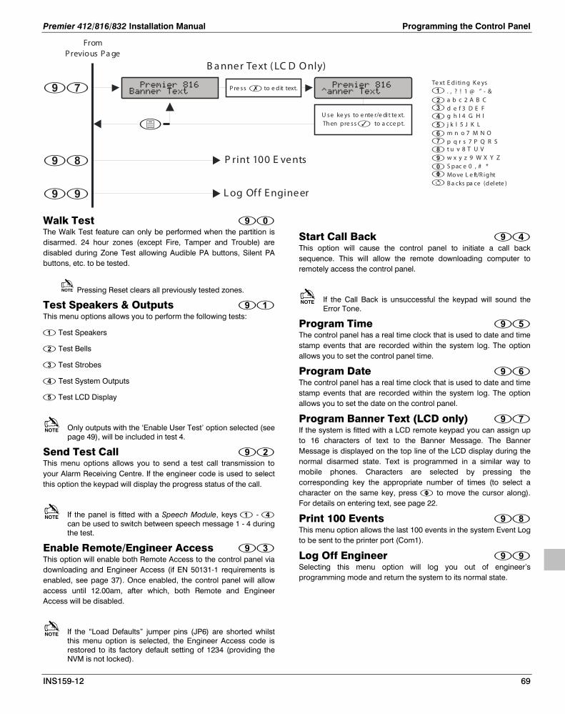
Premier 412/816/832 Installation Manual Programming the Control Panel
INS159-12 69
FromPrevious Pa ge
Te xt E ditin g K e ys
. , ? ! 1 @ ” - & a b c 2 A B C d e f 3 D E F g h I 4 G H I j k l 5 J K L m n o 7 M N O p q r s 7 P Q R S t u v 8 T U V
w x y z 9 W X Y Z S pac e 0 , # * Mo ve L e ft/R ig ht B a cks pa ce (delete )
U se ke ys to e nte r/e dit te xt.Th en pre ss to a cce pt.
P re ss to e dit text.
B a nner Text ( LC D O nly)
L og Of f E ngineer
P rint 100 E vents
Walk Test The Walk Test feature can only be performed when the partition is disarmed. 24 hour zones (except Fire, Tamper and Trouble) are disabled during Zone Test allowing Audible PA buttons, Silent PA buttons, etc. to be tested.
Pressing Reset clears all previously tested zones.
Test Speakers & Outputs This menu options allows you to perform the following tests:
Test Speakers
Test Bells
Test Strobes
Test System Outputs
Test LCD Display
Only outputs with the ‘Enable User Test’ option selected (see page 49), will be included in test 4.
Send Test Call This menu options allows you to send a test call transmission to your Alarm Receiving Centre. If the engineer code is used to select this option the keypad will display the progress status of the call.
If the panel is fitted with a Speech Module, keys - can be used to switch between speech message 1 - 4 during the test.
Enable Remote/Engineer Access This option will enable both Remote Access to the control panel via downloading and Engineer Access (if EN 50131-1 requirements is enabled, see page 37). Once enabled, the control panel will allow access until 12.00am, after which, both Remote and Engineer Access will be disabled.
If the “Load Defaults” jumper pins (JP6) are shorted whilst this menu option is selected, the Engineer Access code is restored to its factory default setting of 1234 (providing the NVM is not locked).
Start Call Back This option will cause the control panel to initiate a call back sequence. This will allow the remote downloading computer to remotely access the control panel.
If the Call Back is unsuccessful the keypad will sound the Error Tone.
Program Time The control panel has a real time clock that is used to date and time stamp events that are recorded within the system log. The option allows you to set the control panel time.
Program Date The control panel has a real time clock that is used to date and time stamp events that are recorded within the system log. The option allows you to set the date on the control panel.
Program Banner Text (LCD only) If the system is fitted with a LCD remote keypad you can assign up to 16 characters of text to the Banner Message. The Banner Message is displayed on the top line of the LCD display during the normal disarmed state. Text is programmed in a similar way to mobile phones. Characters are selected by pressing the corresponding key the appropriate number of times (to select a character on the same key, press to move the cursor along). For details on entering text, see page 22.
Print 100 Events This menu option allows the last 100 events in the system Event Log to be sent to the printer port (Com1).
Log Off Engineer Selecting this menu option will log you out of engineer’s programming mode and return the system to its normal state.

Operating the Alarm System Premier 412/816/832 Installation Manual
70 INS159-12
5. Operating the Alarm System
Introduction
Before attempting to operate the alarm system ensure you have familiarised yourself with all the arming and disarming methods covered in this section.
Access Codes • If you make a mistake whilst entering your Access code,
simply enter the correct Access code.
Arming & Disarming the Alarm System
Checking if the System is Ready to Arm To help prevent faults during arming, a Ready light has been provided on each keypad. The Ready light works as follows:
• If the Ready light is on steady then the alarm system is ready to be armed.
• If the Ready light is flashing then the alarm system has bypassed zones and/or Force Armable zones that are violated, check these zones before proceeding.
• If the Ready light is off then one or more zones are violated, either secure or bypass these zones before proceeding. The keypads will display the zones that are violated:
Active zones are s crolledin s equence on LC D keypad s
Active zones are indicated bythe relevant z one lig hts on
LED Keypads
3
If any unbypassed zones that are not enabled for “Force Arming” are violated at the end of the exit delay this is termed an exit error and the alarm system will go into fail set state (internal alarm). If programmed by the installer the external bell will also sound. Enter a valid user Access code to silence this alarm.
A zone will only be armed when ALL associated partitions are armed but will be disarmed when ANY associated partition is disarmed.
Away Arming The Away arming mode is normally used when leaving the premises. When the system is armed in this mode all detection zones assigned to your partition(s) will be armed.
The Ready light must be on steady before the alarm system can be Away armed.
To Away arm the alarm system proceed as follows:
The light will flash and the exit tone will sound.A rmed
Press
E nter Acce ss code
Press
1
2
3 Le ave the pre mise s , when the sy stem has armed the e xit tone will s top. The system is now Away arme d.
3
3
If the Quick Arm feature is enabled (see page 42) you can omit step 1 from the above procedure.
Stay Arming The Stay arming mode is normally used when the premises will be occupied. When the system is armed in this mode all Interior detection zones assigned to your partition(s) will be bypassed. Before Stay arming check the following:
• Secure or bypass any perimeter zones that are violated.
• Ensure no perimeter zones are bypassed unintentionally.
• Ensure no perimeter Force Armable zones are violated unintentionally.
To Stay arm the alarm system proceed as follows:
T he alarm syste m will arm immediately a nd the light will fla sh.
Arme d
Press
E nter Acce ss code 1
2
3 The sy stem is now S tay a rmed.
3
3
If the Quick Arm feature is enabled (see page 42) you can omit step 1 from the above procedure.
If the system is fitted with a Premier RKP16 Plus then the Stay light will also illuminate when the system is Stay armed.

Premier 412/816/832 Installation Manual Operating the Alarm System
INS159-12 71
Cancelling the Arming Process
To cancel the arming process during the exit delay:
Arming has bee n c anc elled and the ala rm syste m is now disarmed.
Press
E nter Acce ss code 1
2
3
Press
3
3
If the system only has one partition you will not have to perform step 2.
Disarming During Entry
To disarm the alarm system during entry, proceed as follows:
T he entry tone will s top and the light will turn off. T he alarm syste m is now disa rmed.
Arme d
E nter Acce ss code
1
2
3
E nter the premis es via the de s ignated entr y point, the entry tone will sound. Proce ed dire ctly to the
re mote keypad.
3
3
If a valid Access code is not entered before the end of the entry delay, an alarm will occur.
Disarming when not in Entry
To disarm the alarm system when not in entry, proceed as follows:
The light will turn off. The a larm system is now disarmed.
Arme d
Press
E nter Acce ss code 1
2
3
Press
3
3
If the system only has one partition you will not have to perform step 2.
If the Quick Disarm feature is enabled (see page 42) and the system is Stay armed you can omit step 1 from the above procedure.
Disarming after an Alarm
To disarm the alarm system after an alarm, proceed as follows:
The system is disarme d and the keypads displa y the source of the alarm.
E nter Acce ss code 1
2
3
The system must now be reset before you can arm again, see page 75 for details on resetting alarms.
Auto Stay Arming If your installer has enabled the Auto Stay feature the system will automatically Stay arm if the entry/exit zone (front door) is not activated whilst attempting to Away arm the system.
To auto Stay arm your alarm system proceed as follows:
The light will flash and the exit tone will sound.A rmed
Press
E nter Acce ss code
Press
1
2
3 Do NOT le ave the pre mise s during the exit delay. At the end of the exit delay the alarm syste m will S ta y arm.
Changing between Delayed and Instant Stay When Stay arming the system the delayed zones (front door etc) are normally delayed, i.e., when a delayed zone is violated it will start the entry delay timer. However, it is possible to change the delayed zones to instant when the system is in a Stay armed mode. If a delayed zone is violated when the system is in the “Instant Stay” mode the system will generate an alarm immediately.
To change from Delayed Stay to Instant Stay, proceed as follows:
The light will f la sh quic kly.The sy stem is armed.
Arme dIns ta nt S ta y
Pre ss and hold the key until you hear the confirmation tone .
1
2
3
E nsure that the system is a rmed.S ta y
3

Operating the Alarm System Premier 412/816/832 Installation Manual
72 INS159-12
If the system is fitted with a Premier RKP16 Plus the Instant light will also illuminate.
To change from Instant Stay to Delayed Stay, proceed as follows:
T he light will flash s lowly.T he syste m is a rme d.
A rmedDe la yed S tay
Pre ss and hold the key until you hear the confirmation tone .
1
2
3
E nsure that the system is a rmed.I nsta nt S ta y
3
If your system is fitted with a Premier RKP16 Plus the Instant light will go off.
Arming and Disarming Partitions
This section covers arming and disarming partitions. In order to use these procedures the following requirements must be configured:
• The alarm system must be split into one or more partitions.
• Your Access code must be assigned to more than one partition.
• The keypad that you use to operate the alarm system must be assigned to multiple partitions OR your Access code is enabled for Global Access.
Away Arming Partitions This option allows you to Away arm one or more partitions.
To Away arm selected partitions, proceed as follows:
T he light will flash quickly.R ea dy Press - to se le ct/de select partitions ,
e.g. Press to select Partition 2.
Press
E nter Acce ss code 1
2
3
Partition 2 is now selec ted.
4 Press Press
The light will flash and the e xit tone will sound.A rmed
5 L e ave the a rea be ing arme d, whe n the partition has a rme d the exit tone will s top. The se le cte d pa rtition(s ) is
now Away a rme d.
3
3
3
3
If the Quick Arm feature is enabled (see page 42) you can omit step 1 from the above procedure.
Stay Arming Partitions This option allows you to Stay arm one or more partitions.
To Stay Arm selected partitions, proceed as follows:
T he light will flash quickly.R ea dy Press - to sele ct/de se lect pa rtitions ,
e.g. Press to se lect Pa rtition 1.
Press
E nter Acce ss code 1
2
3
Partition 1 is now selected.
4 Press
5
T he sele cted partition(s ) will a rm immediately and the light will flash.A rmed
The selecte d partition(s ) is now armed.S ta y
3
3
3
3
3
Disarming Partitions This option allows you to disarm one or more partitions.
To disarm selected partitions, proceed as follows:
T he light will flash quickly.R ea dy Press - to sele ct/de se lect pa rtitions ,
e.g. Press to se lect Pa rtition 2.
Press
E nter Acce ss code 1
2
3
Partition 2 is now selected for disarm.
4 Press
5 T he sele cted partitions a re disa rme d.
Press
3
3
3
3

Premier 412/816/832 Installation Manual Operating the Alarm System
INS159-12 73
Changing to another Partition Normally the remote keypad that you use will be assigned to a particular partition and therefore the zone and status lights will indicate information relevant to the assigned partition. However, you can temporarily switch the remote keypad to a different partition so that the zone and status lights indicate the information relevant to the partition that you have selected. Whilst in this mode you can also use your Access code to arm/disarm the partition you have selected (providing you have access to the selected partition).
In order to use the cross partitioning feature, it is recommended that the system is configured as follows:
• Cross partitioning must be enabled (see page 37).
• The user must be assigned to multiple partitions.
• The user should be set for “Local Partition Access Only”, see page 67.
• The remote keypads should only be assigned to a single partition.
To change to another partition, proceed as follows:
E nter partition - ,e.g. Press to se lect Pa rtition 2.
Press 1
2
The remote keypad will now indicate information relevant to the selec ted partition.
3
3
After changing to the selected partition, the remote keypad will only remain in the selected partition for 10 seconds after the last key press. However if an Access code is entered whilst the remote is in this mode, the remote keypad will remain in the selected partition for 1 minute after the last key press.
Bypassing Zones
Manually Bypassing Zones Bypassing a zone prevents it from causing an alarm.
After manually bypassing a zone, the bypass will remain in place until the zone is manually unbypassed.
The bypass mode will time-out if no key is pressed for 60 seconds.
24 hour zones cannot be unbypassed if they are violated.
To manually bypass zones, proceed as follows:
T he light will flash quickly.R ea dy E nter the zone numbe r ,
e.g. E nte r to se le ct Zone 2.
Press
E nter Acce ss code 1
2
3
T he selec ted zone is now bypa ssed. Re peat s tep 3 to bypass additional zone s .
4
5 Once the selected zones have be en bypa ssed pre ss :/ to Awa y arm
to S tay arm to return to the normal disa rme d state
3
3
3
If the Quick Bypass feature is enabled (see page 42) you can omit step 1 from the above procedure.
When one or more zones are bypassed the Ready light will flash and if the system is fitted with a Premier RKP8/16 Plus or LCD remote keypad then the Bypass light will also illuminate.
Unbypassing Zones To manually unbypass zones, perform the manual bypass procedure on a zone that is already bypassed.
• 24 hour zones cannot be unbypassed if they are still violated.
• If the “Reinstate Bypassed Zones on Disarm” option is enabled (see page 37) all zones will automatically be unbypassed each time the system is disarmed.

Operating the Alarm System Premier 412/816/832 Installation Manual
74 INS159-12
Group Bypass The Group Bypass feature allows you to bypass a predefined group of zones. The alarm system has up to four groups, see page 29 on programming bypass groups.
To Bypass a group of zones, proceed as follows:
The keypad will display the bypasse d zones . If re quire d, zones c an be added or removed from the group by entering the require d zone number ,
e .g. E nter to add Zone 5 .
E nter bypass group - followed by
E nter Acce ss code 1
2
3
T he selec ted zone is now bypa ssed. Re peat s tep 3 to bypass additional zone s .
4
5 Once the selected zones have be en bypa ssed pre ss :/ to Awa y arm
to S tay arm to return to the normal disa rme d state
3
3
3
If the Quick Bypass feature is enabled (see page 42) you can omit step 1 from the above procedure.
When one or more zones are bypassed the Ready light will flash and if the system is fitted with a Premier RKP8/16 Plus or LCD remote keypad then the Bypass light will also illuminate.
Quick Bypass and Arm The Quick Bypass and Arm feature allows you to Bypass a predefined group of zones and Away or Stay arm the system. The alarm system has up to four groups, see page 29 on programming bypass groups.
To Quick Bypass a group of zones and Away arm, proceed as follows:
E nte r bypass group - 1
2
3
Press Press
The a nd lights will flash and the exit tone will sound.
A rmed R ea dy
Whe n the syste m is Awa y armed with the selected group of zone s bypa sse d.
exit tone stops , the
To Quick Bypass a group of zones and Stay arm, proceed as follows:
E nte r bypass group - 1
2
3
Press
T he alarm syste m will arm immediately a nd the and lights will fla sh.
Arme dRe ady
T he system is S tay a rme d with the se le cte d group of zone s bypa sse d.
3
3
The Quick Arm feature must be enabled to use this feature (see page 42).

Premier 412/816/832 Installation Manual Operating the Alarm System
INS159-12 75
Reset Alarms
This function is used to reset any standing alarms and service faults. It is also used to reset detectors with a latched alarm indication, e.g., Smoke Detectors.
To Reset Alarms, proceed as follows:
The ke ypad will bleep a nd the a la rm system will rese t all latching dete ctors and a tte mpt to clear any sta nding
or .A la rms S er vice F aults
Press
E nter Acce ss code
Press
1
2
3
3
3
Last Alarm Log
The control panel has a memory that stores the zones that caused an alarm when the system was last armed.
To view the alarm memory, proceed as follows:
T he keypad will display the zones that caused an alarm when the syste m wa s last a rme d.
Press to return to the normal disa rme d state .
Press
E nter Acce ss code 1
2
3
3
3
Service Faults
The response to a Service Fault condition is programmed by the installer but is normally limited to the keypad buzzer. To silence the Service Fault alarm, enter your Access code.
A flashing Service light indicates a new fault condition. The alarm system cannot be armed whilst a new fault exists. The Service light will remain flashing until the new fault is acknowledged, after which it will revert to a steady yellow and the alarm system can be armed. The Service light will remain steady until all faults have been cleared.
After a new Service Fault has been acknowledged the Service light will revert to steady yellow and the alarm system can be armed. The Service light will remain steady yellow until all faults have been cleared.
AC Fail and Telephone Line Fault can each have a delay programmed. The Service light will turn steady yellow immediately
on either of these faults but no Service Fault Alarm (transmission or audible alarm) will occur unless the delay expires.
If your installer has disabled AC fail acknowledgement the Service light will flash “rapidly” during an AC fail condition. The system can be armed without requiring acknowledgement of this fault.
Acknowledging a New Service Fault
New service faults can be acknowledged as follows:
The k eypad will displa y all S e rvice Faults .
Press or to acknowledge the fault and re turn to the normal disarmed state.
Press
E nter Acce ss code 1
2
3
3
3

Operating the Alarm System Premier 412/816/832 Installation Manual
76 INS159-12
View Service Faults
Standing faults can be viewed as follows:
1. Press the key followed by the key.
The keypad will display any Service Faults (see tables).
On completion press the key.
Service Faults Displayed on LED Keypads
Light Fault Condition
1
General Warnings
Press (Key 1) to view the warning, lights 1-5 will indicate the
following:-
1 = AC Fail 2 = Arming Fob has Low Battery 3 = Soak Test Active
2 Telephone Line Fault
3 2-Wire Smoke Alarm
4
Box Tamper & Auxiliary Input:
Press to view type, lights 1 - 8 indicate:
1 = Box Tamper 4 = Auxiliary Tamper * 2 = Auxiliary Tamper 5 = Bell Tamper * 3 = Auxiliary PA 6 = Radio Plus Tamper 7 = Low Fob Battery 8 = User Code Tamper * = UK Bell Module
5 Date or Time Lost
6 Zone Tamper/Trouble
Press to view zone number
7 Keypad Tamper/Removed
Press to view keypad number
8
Equipment Faults
Press to view fault type, lights 1 - 8 indicate: 1 = Output 1 Fault 2 = Output 2 Fault 3 = Siren/Bell Fault 4 = 2-Wire Smoke Sensor Fault 5 = Auxiliary Fuse Failed 6 = Battery Fault
7 = Service Timer/Zone Soak Test Failed 8 = Com1 Fault or Fail To Communicate
Service Faults Displayed on LCD Keypads
LCD Fault Condition
AC Fail
One or more zones on soak test
1 to continue arming 0 to exit arming
Key fob has a low battery (Message above shown)
Shown after invalid user code attempts
Telephone Line Fault
2-Wire Smoke Alarm
Box Tamper
Auxiliary Tamper (Aux Input)
Auxiliary Tamper (UK Bell Module)
Bell Tamper (UK Bell Module)
Auxiliary PA (Aux Input)
Date or Time Lost
Zone Tamper/Trouble
Keypad Tamper/Removed
Output 1 Fault
Output 2 Fault
Siren/Bell Fault
2-Wire Smoke Sensor Fault
Auxiliary Fuse Failed
Battery Fault
Service Timer/Zone Soak Test Failed
Com1 Fault or Fail To Communicate

Premier 412/816/832 Installation Manual Operating the Alarm System
INS159-12 77
Anti-code Reset
This feature is normally used in the UK where users are not permitted to reset the panel following a communicated alarm. However, the user can reset the panel after entering a unique remote reset number, which is supplied by their installer or ARC.
To perform an Anti-code Reset, proceed as follows:
The ke ypad will display a ra ndomly ge ne ra ted 4-
digit C ode .
Press
E nter Acce ss code 1
2
3 Contact the ARC to obtain a Anti-c ode R eset number.
E nter the Anti-c ode Rese t number given to you by the ARC .
I f the code is ac cepte d, the keypa d will sound a n acce ptance tone a nd the system will rese t and return to
the normal disarme d state .
4
Toggle Chime On and Off
When a zone is enabled for Chime the keypad will generate a Chime tone every time the zone is violated. This function allows you to turn the Chime feature on and off.
To toggle Chime on and off, proceed as follows:
If C hime was off, it will turn on a nd the ke ypad will sound the Chime tone . If Chime was on, it will turn off
and the ke ypad will sound the a ccepta nce tone .
E nter
E nter Acce ss code 1
2
3
Press
3
3
Change User Code
All users of the alarm system can change their own Access code number.
To change your Access code, proceed as follows:
E nter ne w code If the code is 4 or 5 digits the / ke y to
a ccept.
pre ss
E nter
E nter Acce ss code 1
2
3
4
5 T he keypad will sound an a ccepta nce tone if the new Access code wa s acc epted. If you hea r a n e rror tone
( low), ple ase re pe at from ste p 1 .
Re -e nte r ne w code
3
3
3
View Log (LCD Only)
The control panel has an Event Log, which stores all system activity i.e., users entering their codes to arm and disarm the system, alarm events, faults etc. Each event is time and date stamped.
To view the Event Log, proceed as follows:
D ay
E ve n t Ty pe(sh o wing Z o ne Text)
T im eP artition s D ay /M o nth
E ve n t Ty pe(Alar m Type & Z on e N o )
T im e
P res s to to g glein for ma tio n dis pla yed
E nter
E nter Acce ss code 1
2
3
4 Press to sc roll up a nd down through the log.Press to when finished.
Abort Communications
This option aborts any communications to the Alarm Receiving Centre.
To Abort Communications, proceed as follows:
T he keypad will ble ep and the ala rm syste m will a bort all communica tions to the Ala rm R ece iving C entre.
E nter
E nter Acce ss code 1
2
3
3
3

Specifications Premier 412/816/832 Installation Manual
78 INS159-12
6. Specifications
Control Panel
All Models Large & Small Polymer
Current Current Consumption 50mA Maximum Current Available 0.3A charge 1.1A
Rated Output Battery
Arrangement Battery Charge
Rated Output (Amps) 12h
1 x 7Ah 0.3A 0.533A
Standby and Recharge Times EN50131-1 Grade 1 Grade 2
Minimum Standby Period 12h 12h Maximum Recharge Time 72 Hrs 72 Hrs
Control Panel Power Supply Type A Rated Input: 100V - 240V @ 50/60Hz; 1A Rated Output Current @ 55°C:: 1.5A MAX Rated Output Voltage: 13.7Vdc +/- 2% Mains Terminal Block Fuse: 250Vac; 3-3.15A Slow/Medium Blow Maximum rating of each power output (note that these are not considered to be "independent power outputs" according to EN50131-6 Aux 12V
Siren Network Battery
1.0A 1.0A 1.0A 2.5A
Standby Current 50mA Output Voltage Range: 13.0V to 13.9V Maximum Ripple Voltage: 0.5V pk-pk Battery type: sealed lead acid, up to 7Ah, Maximum
recharge time 72h Battery Low Voltage Signal: 10.5V Deep Discharge protection: 8.0V Fuses (Electronic PTC) F1 (2.5A) Battery Fuse
F2 (900mA) Auxiliary 12V power fuse F3 (900mA) Siren/Bell output fuse F4 (900mA) Network fuse
Housing (Polymer) 3mm Polycarbonate Dimensions (Small) (W x H x D) 282mm x 225mm x 80mm Dimensions (Large) (W x H x D) 305mm x 263mm x 98mm Battery Compartment One 12V 7.0Ah battery Packed Weight 1.2 - 1.5 Kg (Approx)
All Models Metal
Current Current Consumption 50mA Maximum Current Available 0.3A charge 1.0A 0.75A charge 1.9A
Rated Output Battery
Arrangement Battery Charge
Rated Output (Amps) 12h 24h 30h 60h
1 x 7Ah 0.3A 0.533A 0.241A 0.183A X
1 x 17Ah 0.3A 1.36A 0.658A 0.516A 0.233A
0.75A 1.0A 0.658A 0.516A 0.233A
Standby and Recharge Times EN50131-1 Grade 1 Grade 2
Minimum Standby Period 12h 12h Maximum Recharge Time 72 Hrs 72 Hrs
Jumper Settings Battery Arrangement Recharge Time Charge Selection
1 x 7Ah < 24Hrs 0.3A 1 x 17Ah < 24Hrs 0.75AA
< 72Hrs 0.3A
Control Panel Rated Input: Rated Output Current@40°C:
220V - 240V @50/60Hz; 1A 2.5A MAX
Rated Input: Rated Output Current@40°C:
100VV - 120V @50/60Hz; 1A 2.3A MAX
Rated Output Voltage: 13.7Vdc +/- 2% Mains Terminal Block Fuse: 250Vac; 3-3.15A Slow/Medium Blow Rated Input: Rated Output Current@40°C:
220V - 240V @50/60Hz; 1A 2.5A MAX
Maximum rating of each power output (note that these are not considered to be "independent power outputs" according to EN50131-6 Aux 12V
Siren Network Battery
1.0A 1.0A 1.0A 2.5A
Standby Current 50mA Output Voltage Range: 13.0V to 13.9V Maximum Ripple Voltage: 0.5V pk-pk Battery type: sealed lead acid, up to 7Ah, Maximum
recharge time 72h Battery Low Voltage Signal: 10.5V Deep Discharge protection: 8.0V Fuses (Electronic PTC) F1 (2.5A) Battery Fuse
F2 (900mA) Auxiliary 12V power fuse F3 (900mA) Siren/Bell output fuse F4 (900mA) Network fuse
Housing (Metal) 1mm Steel Dimensions (W x H x D) 315mm x 415mm x 100mm Battery Compartment Up to One 12V 18Ah battery Packed Weight 4.0Kg (Approx)
All Models Electrical
Current Consumption Quiescent Current: Alarm:
<50mA <150mA
Zones Number: EOL Resistor Value:
8 3K3
Panel Outputs O/P 1 - Supervised: O/P 2 - Supervised: O/P 3 - 8:
1A switched to 0V 1A switched to 0V 100mA switched to 0V
Siren Output (Supervised) Speaker Mode: Bell Mode:
Minimum load 4Ω 1A switched to 0V
2-Wire Smoke Detectors: ESL429CT System Sensor 2100TS
Onboard Communicator Protocols:
Pulse Format, Express Format, Fast Format, Contact ID, SIA Level 2/3, Pager and Mobile Phone
Dialling Formats: REN: Approval:
Pulse or DTMF 1 CTR21, DPT-TE-001
Non Volatile Memory Component 412, 412 Plus, 816, 816 Plus: 832
24LC128 24LC256
EN50136-1-1 & EN50136-2-3 The inbuilt communicator complies with the requirements of EN50136-2-3 , EN50136-1-1 and are suitable for use in systems designed for use with ATS levels 1 or 2 and environmental class 1 or 2 – i.e. systems using notification options up to and including 2B. With the PSTN functioning normally, the ATS will comply with the required performance levels subject to the ARC being suitably equipped.
These units may be used for Downloading, Remote Servicing or SMS text messaging purposes in systems at ALL security grades.
Environmental Operating Temperature: -10°C to +55°C
+14°F to +131°F Maximum Humidity: 95% non-condensing EMC Environment: Residential/Commercial/Light
Industrial or Industrial

Premier 412/816/832 Installation Manual Specifications
INS159-12 79
Remote Keypads
ACE Type B Electrical Operating Voltage: 9 - 13.7VDC Current Consumption
Nominal (model dependant): When fully back lit:
10mA 200mA
Zone Indicators Premier RKP4/8/16: Premier RKP8/16 Plus: Premier LCD/LCDL/FMK/SMK:
LED (4/8/16) LED (8/16) 32 Character (Standard/Large)
Environmental
Operating Temperature: -10°C to +55°C +14°F to +131°F
Maximum Humidity: 95% non-condensing
EMC Environment: Residential/Commercial/Light Industrial or Industrial
Physical Dimensions:
Premier RKP4/8/16 Premier RKP8/16 Plus/LCD/-L/P
140mm x 105mm x 35mm 145mm x 115mm x 30mm
Packed Weight: 380g
Remote Zone Expander
ACE Type B Electrical Operating Voltage: 9 - 13.7VDC Current Consumption
Nominal: In Alarm with Speaker:
35mA 180mA
Zones Number: EOL Resistor Value:
8 3K3
Speaker Output: Minimum load 4Ω Outputs
O/P 1 & OP 2: 100mA switched to 0V
Environmental
Operating Temperature: -10°C to +55°C +14°F to +131°F
Maximum Humidity: 95% non-condensing
EMC Environment: Residential/Commercial/Light Industrial or Industrial
Physical Dimensions: 145mm x 115mm x 30mm Packed Weight: 260g approx.
Local Zone Expander
Electrical Operating Voltage: 9 - 13.7VDC Current Consumption: 35mA Connection: Plugs onto control panel Zones
Number: EOL Resistor Value:
8 3K3
Environmental
Operating Temperature: -10°C to +55°C +14°F to +131°F
Maximum Humidity: 95% non-condensing
EMC Environment: Residential/Commercial/Light Industrial or Industrial
Physical Dimensions: 83mm x 50mm x 12mm Packed Weight: 50g
Safety Notes
1. The Texecom Switch mode Power supply is a multi voltage device with no user adjustment.
2. Use of a non Texecom power supply is prohibited and will invalidate the warranty.
3. Only use batteries of the specified type.
4. Dispose of used batteries safely according to the manufacturer's instructions.
5. Locate the battery inside the panel space provided.
6. This equipment is designed for dry indoor use only.
7. When replacing a fuse always observe the specified rating and type - failure to do so is dangerous and will invalidate the warranty. Fuses should comply with IEC 127.
8. The press-seal bag must not be stored inside the panel.
Standards
Texecom declares that this product complies with the requirements of the following directives:
• 2004/108/EC EMC Directive • 2006/95/EC LVD Directive • 2011/65/EU RoHS Directive
The product therefore meets all the requirements to enable it to be CE marked.
Weee Directive: 2012/19/EU (WEEE directive): Products marked with this symbol cannot be disposed of as unsorted municipal waste in the European Union. For proper recycling, return this product to your local supplier upon the purchase of equivalent new equipment, or dispose of it at designated collection points. For more information see: www.recyclethis.info.
This product is suitable for use in systems designed to comply with EN 50131-1 at grade 2 and environmental class II.
EN 50131-1/3/6 Compliance In order to comply with the requirements of EN 50131-1, EN 50131-3 and EN 50131-6 the following programming and system configuration must be implemented:
• Menu Options 39 1-8 must all be turned ON, see page 40.
• EN 50131-1 Requirements must be programmed as “Enabled”, see page 37.
• The “Permanent Keypad Status Display” option must be programmed to “Disabled” for all remote keypads, see page 42. In addition the “Courtesy Delay” timer must not be set above 180 seconds, see page 36.
• The “Partition Entry Delay” timers must not be programmed above 45 seconds, see page 31.
• The “Partition Bell Delay” timers must not be programmed above 10 minutes, see page 31.
• The “Partition Bell Duration” timers must be programmed between 2 and 15 minutes, see page 31.
• “Quick Arm”, “Quick Disarm” and “Quick Bypass” option must be programmed to “Disabled” for all remote keypads, see page 42.
• The “Tamper Alarms Cause a Trouble While Disarmed” option must be “Enabled”, see page 37.

Specifications Premier 412/816/832 Installation Manual
80 INS159-12
• Do not fit more than 10 unpowered detectors per zone.
• Do not fit more than one non-latching powered detector per zone.
• Do not mix unpowered detectors and non-latching detectors on a zone.
• A Type W must not be used.
Prioritisation of signal and message processing indications. First alarm indications followed by any other events during that set period, will be reported on the keypad and will scroll, viewing of these events can be controlled by the up and down key on the keypad.
Compliance Label If the system is programmed to NOT comply with the requirements of EN50131-1 or EN50131-3 , or the system is installed at Grade 1 then the compliance label must be removed.
Inhibit functions For Alarms and Tamper the inhibit function is controlled by the Swinger shutdown counter which is programmable and is defaulted to 3.
See page 27 & 34 for details.
Minimum Logical Keys 10,000 for 4 digit code 100,000 for 5 digit code 1,000,000 for 6 digit code
User codes must be programmed to be a 6 digit code to comply with INCERT
The number of disallowed codes Premier 412 = 0 Premier 816 = 0 Premier 832 = 0
Dependant on the use of the Black Listed codes function available via Wintex, a maximum of 16 codes may be Black Listed
Warranty
All Texecom products are designed for reliable, trouble free operation. Quality
is carefully monitored by extensive computerised testing. As a result the
control panel is covered by a two-year warranty against defects in materials or
workmanship.
As the control panel is not a complete alarm system but only a part thereof,
Texecom cannot accept responsibility or liability for any damages whatsoever
based on a claim that the control panel failed to function correctly.
Due to our policy of continuous improvements Texecom reserve the right to
change specification without prior notice.

Premier 412/816/832 Installation Manual Quick Reference Guide
INS159-12 81
7. Quick Reference Guide
Menu Function Page
Programming Zones
All Zone Options 26
Zone Type 26
Null
Delay 1
Delay 2 Interior Follower
Interior Instant
Perimeter Instant Fire
PA Silent PA Audible
Medical
24-Hour Tamper
Trouble
24-Hour - Gas 24-Hour - Water
24-Hour - High Temp
24-Hour - Low Temp Momentary Key Switch
Maintained Key Switch Push To Set
Zone Wiring 27
Normally Closed
Normally Open
Single EOL - N/C & N/O
Single EOL - N/O (Fire) Single EOL - N/C
Single EOL - O/C Tamper
Single EOL - S/C Tamper
Double EOL
Zone Doubled Triple EOL
Zone Attributes 1 27
Enable Instant Internals
Enable Bell Delayed Bell
Pulsed Bell
Enable Instant Strobe
Enable User Chime Enable Transmission Delay
Enable Transmission
Zone Attributes 2 28
Enable Manual Bypass
Enable Stay Bypass
Enable Force Arming Quick Response Time
Enable Cross Zoning
Enable Soak Test
Enable Swinger Shutdown Enable Double Knock
Zone Attributes 3 28
Change to Delay 1 on Stay Arm
Change to Follower on Stay Arm Zone Warning (* Keyswitch is Instant Arming)
Auto Reinstate if Force Armed (* Keyswitch will Stay Arm/Disarm) Disable Keyswitch if Away Armed
Disable Exit Faults (* Disabled Auto Arm)
Truncate Exit Delay (* Monitor Only) Forced Walk Test
* Attributes for Key Switch zone types
Zone Partitions & Groups 28
Enabled for Partition 1
Enabled for Partition 2
Enabled for Partition 3 Enabled for Partition 4
Enable for Bypass Group 1
Enable for Bypass Group 2
Enable for Bypass Group 3 Enable for Bypass Group 4
Zone Text 29
. , ? ! 1 @ ” - &
a b c 2 A B C d e f 3 D E F
g h I 4 G H I j k l 5 J K L
m n o 7 M N O
p q r s 7 P Q R S
t u v 8 T U V w x y z 9 W X Y Z
Space 0 , # * Move Left/Right
Backspace (delete)
Programming Partitions
Partition Exit Time 31
Menu Function Page
Partition Entry Delay 1 Time 31
Partition Entry Delay 2 Time 31
Partition Communicator Delay 31
Partition Bell Delay 31
Part Bell Duration 31
Partition Options 31
Enable Auto Bypass Mode
Stay Armed Exit is Silent
Enable Remote Arming Enable Remote Disarming
Enable Local Exit Tones Stay Armed Entry is Instant
Stay Armed Exit is Delayed
Only Start Exit when Partition is Ready
Partition Auto Arm/Disarm 32
Arm with Control Timer 1
Arm with Control Timer 2
Arm with Control Timer 3 Arm with Control Timer 4
Disarm with Control Timer 1
Disarm with Control Timer 2
Disarm with Control Timer 3 Disarm with Control Timer 4
Equipment Areas 32
Auxiliary Input Areas
Panel Bell Areas
Bell Squawk Areas
Masked when Armed
Programming Global Options
System Timers 35
AC Fail Delay
Line Fault Delay
Cross Zone Time
Zone Soak Test Time Restore Reporting Delay
Output Short Pulse Time Zone Response Time
Transmission Abort
Test Transmission Time
Courtesy Delay
Service Timer
2-Wire Verified Delay Alarm Confirmation Delay
Activity Time Window Poll IP Every
System Counters/Levels 36
Swinger Shutdown Count
Panel Speaker Volume
Chime Volume
Clock Adjustment
Language Selection
Country Operation Code
System Control Timers 36
System Options 1 36
Clock = Crystal
Battery Connection Supervision
Battery Dynamically Load Tested Panel NVM is Locked
Power Savings During AC Mains Failure Line Fault Overrides Bell Delay
Two-Wire Smoke Detection on O/P 1
Convert Siren Output from Voltage to Speaker Driver
System Options 2 37
Tamper Alarms Cause a Trouble While Disarmed
Tamper Alarms Cause a Trouble While Stay Armed
Defer Reporting of Non-Zone Restorals
Use Delay Timer to Defer Non-Zone Restorals Inhibit Keyswitch Operation Upon EOL Tamper
Away Arm Overrides Alarm Transmission Delay

Quick Reference Guide Premier 412/816/832 Installation Manual
82 INS159-12
Menu Function Page Defer Reporting of Zone Restorals
Use Delay Timer to Defer Zone Restorals
System Options 3 37
Away Arm Exit Error Doesn’t Sound Bell
Zone Test - Silence on No Violation
Alarm Status Light Indicates Fire Enable Entry/Exit Tones for Panel Speaker
Enable Cross Partitioning
Enable EN 50131-1 Requirements Reinstate Bypassed Zones on Disarm
Invert Panel Bell/Siren Output
Hardware Options 38
Panel Output 1 Supervised for Faults
Panel Output 2 Supervised for Faults
Siren/Bell Output Supervised for Faults Panel Box Tamper Switch Monitored
Auxiliary Fuse Supervised for Faults Battery Supervised for Faults
AC Mains Supply is Monitored
Telephone Line Is Monitored
Auxiliary Input Options 38
Not Used
Auxiliary Tamper
Remote Reset Telephone Line Monitor
Panic Alarm Silent PA
Latched Key switch
Momentary Key switch
- Miscellaneous Options 1 38
Enable Bell Squawk on AWAY Arm/Disarm
Enable Bell Squawk on STAY Arm/Disarm Disable AC Fail Acknowledgement
Disable Open/Close Reporting on STAY Arm
Cross/Double Knock Timer is in Minutes Disable Zone Bypass when Armed
Activated Zones Cause Alarm during Exit Control Timer 4 Performs Battery Test
- Miscellaneous Options 2 39
Disable Service Fault Acknowledgement
Enable User Reset for Alarms Disable Online Printing
Enable Bell Module and UK Options
Enable DD 243:2002 Options Enable Confirmation after Entry Time-Out
Invert Auxiliary Input Operation Auto BST/GMT Time Change
- Miscellaneous Options 3 39
Enable User Tamper Reset
Allow Engineer Access when Armed
EN50131 40
Fob Low Battery Arming
Indicate Zone Soak Test Soak Test Acknowledgement
Entry Stray Notification
Entry Timeout Notification Expander Lost
User Code Entry AC & Battery Fail Latch
Menu Function Page
Programming Remote Keypads
Keypad Options 1 42
Partition 1 Operation
Partition 2 Operation
Partition 3 Operation
Partition 4 Operation Permanent Keypad Status Display
Press Any Key for Display Display Zones vs. Partitions
Wrong Code Attempts = Code Tamper
Keypad Options 2 42
Code Tamper Causes a Tamper Alarm
Keypad Activation of Fire Alarm
Keypad Activation of Medical Alarm Keypad Activation of PA Alarm
Keypad PA Alarm is Silent
Quick Arm with Keypad ARM Key Quick Disarm with Keypad DISARM Key
Quick Bypass with Keypad BYPASS Key
Keypad Options 3 42
Fire Alarm Tones from Keypad
Burglary Alarm Tones from Keypad
Trouble Tones from Keypad Acceptance Tones from Keypad
Error Tones from Keypad
Chime Tones from Keypad Entry Tones from Keypad
Exit Tones from Keypad
Keypad Options 4 43
Enable Keypad Zones (RKP8/16 Plus & Premier LCD/LCDL)
Disable Keypad Lid Tamper
Zone Shift by 4 Zone Shift by 8
Zone Shift by 16
Programming Remote Expanders
Expander Partitions 44
Partition 1 Operation
Partition 2 Operation Partition 3 Operation
Partition 4 Operation
Expander Tones 44
Fire Alarm Tones from Expander
Burglary Alarm Tones from Expander
Trouble Tones from Expander Acceptance Tones from Expander
Error Tones from Expander
Chime Tones from Expander Entry Tones from Expander
Exit Tones from Expander
Expander Volume Level 44

Premier 412/816/832 Installation Manual Quick Reference Guide
INS159-12 83
Menu Function Page
Programming System Outputs
Panel Outputs 47
Fast Format Channels 47
Expander 1 Outputs 47
Expander 2 Outputs 47
Expander 3 Outputs 47
Keypad Outputs 47
System Output Types 00 Courtesy
01 Successful Transmission 02 Log 80% Full
03 Program Mode Selected 04 Download In Progress
05 Timed Arming Countdown
06 Zone Soak Test Active 07 Zone Soak Test Failed
08 Latched AC Fail 09 Telephone Line Fault
10 Smoke Alarm
11 Box/Auxiliary Tamper 12 Date Time Loss
13 Zone Trouble/Tamper 14 Keypad Tamper/Removed
15 Service Fault 16 Output 1 Fault
17 Output 2 Fault
Partition Output Types 00 PA Alarm 01 Duress Alarm
02 Burglar Alarm 03 Medical Alarm
04 24Hr - Water Alarm
05 24Hr - Gas Alarm 06 24Hr - Low Temp Alarm
07 24Hr - High Temp Alarm 08 Tamper
09 Trouble
10 Fire 11 Fire Fault
12 Bell 13 Strobe
14 Entry 15 Exit
16 Armed
17 Stay Armed 18 Ready
Zone Output Types 01 - 32 Zone Mimic 01 - 32
Output Attributes 1 Partition 1
2 Partition 2 3 Partition 3
4 Partition 4
18 Siren/Bell Fault
19 Smoke Sensor Fault 20 Auxiliary Fuse Fault
21 Latched Battery Fault 22 Service Required/Test Fail
23 Fail To Communicate
24 Control Timer 1 Active 25 Control Timer 2 Active
26 Control Timer 3 Active 27 Control Timer 4 Active
28 PC Output 1
29 PC Output 2 30 Walk Test
31 Confirmed Alarm 32 ARC 2 Active
33 Zones Locked Out 34 AC Fail
35 Battery Fault
36 Poll Timer
19 Bypass 20 Sensor Reset on Exit
21 Sensor Reset on Reset
22 Single Pulse on Arming 23 Double Pulse on Arming
24 Chime 25 Door Strike
26 Cross Zone Time Active
27 Single Pulse on Disarming 28 Reset Required
29 Acknowledgement Required 30 Confirmed Alarm
31 Alarm Abort
32 Away Armed 33 Away Armed/Exit
34 Detector Latch 35 Armed/Alarm
36 Arm Failed
37 All Armed
33 - 64 Zone Alarm 01 - 32
5 User Test 6 Inverted
7 Latching 8 Pulsed
Menu Function Page
Programming The Communicator
Communicator Options 52
Enable On-Board Communicator
Enable DTMF Dialling Switch to Pulse Dialling after 3rd Attempt
Enable European Pulse Dialling Enable Auto Test Transmission
Enable Cancel Call Waiting
Enable Backup to Alarm Receiving Centre Enable Blind Dialling
ARC 1 Communicator Menu 52
Primary and secondary telephone numbers Account Numbers (partitions 1-4) Protocol Type: Disabled Pulse Format Express Format Fast Format/Speech Module Contact ID SIA Level 2/3 Pager Dial Attempts Partition Options: Report for Partition 1 Report for Partition 2 Report for Partition 3 Report for Partition 4 Reporting Options: Priority Alarm and Cancel Events Alarm and Cancel Events Open and Close Events Bypass and Unbypass Events Maintenance Alarm Events Tamper Alarm Events Test Transmission Events Restore Events
Pulse Format Options: Use 1900Hz Carrier Use 40 PPS Baud Rate Enable Parity Use 2 Digit Events Use 2300Hz Handshake Use 2300Hz Kiss-Off Use Fast/Slow Format Fast Format Reporting Channels Report Channel 1 Report Channel 2 Report Channel 3 Report Channel 4 Report Channel 5 Report Channel 6 Report Channel 7 Report Channel 8 Protocol Options: Disable SIA Modifier Blocks/Enable Speech Module Disable Events for Each Partition Pager Terminator = * (Star) Send Pager Terminator Twice/Send SIA Text Pager DTMF Tones = 500mS Disable Zone Restorals Communication Acknowledgement Tone
Connect via IP
ARC 2 Communicator Menu 55

Quick Reference Guide Premier 412/816/832 Installation Manual
84 INS159-12
Menu Function Page
Fast Format Restore Channels 55
Report Restore on Channel 1
Report Restore on Channel 2 Report Restore on Channel 3
Report Restore on Channel 4
Report Restore on Channel 5 Report Restore on Channel 6
Report Restore on Channel 7 Report Restore on Channel 8
Fast Format Open/Close Channels 56
Report Open/Close on Channel 1
Report Open/Close on Channel 2 Report Open/Close on Channel 3
Report Open/Close on Channel 4
Report Open/Close on Channel 5 Report Open/Close on Channel 6
Report Open/Close on Channel 7 Report Open/Close on Channel 8
Cancel Call Waiting 56
Programming Download Options
Download Menu 57
Download Options: Enable Attended Download
Enable Unattended Call Back Enable 2-Call Answer Phone Defeat
Restrict Download when Armed Download when Part Armed
Disconnect Telephone Line
Download Telephone No UDL Password
Call Back Attempts Ring Count Com1 Device Type ComIP/SMG Address and Port ComIP Gateway ComIP Subnet Mask Com2 Device Type Chiron Iris Data Setup Access Point Name User Name
Password
Programming Reporting Codes
Zone Alarm/Restore Codes 63
Zone Bypass/Unbypass Codes 63
Non Zone Alarm/Restore Codes 63
Programming Users
Program User 66
User Options 1 66
Enable for Partition 1
Enable for Partition 2 Enable for Partition 3
Enable for Partition 4
Allow Arming
Allow Bypassing Allow Disarming
Allow User Functions
User Options 2 66
Enable One Time Use Access Code
Time Lock Code with Control Timer 1 Enable Open Reporting
Menu Function Page Enable Close Reporting
Enable User as Duress Code Activate Door Strike Output
Allow Global Bell/Sounder Silence
Disable Remote Access
User Options 3 67
Allow Engineer Code Programming
Allow NVM Locking
Allow Engineer Programming Allow Test Call Transmission
Allow Alarm/Fault Acknowledgement Allow User Programming
Allow User Code Programming
Local Partition Access Only
User Text 67
. , ? ! 1 @ ” - &
a b c 2 A B C d e f 3 D E F
g h I 4 G H I
j k l 5 J K L m n o 7 M N O
p q r s 7 P Q R S
t u v 8 T U V w x y z 9 W X Y Z
Space 0 , # *
Move Left/Right Backspace (delete)
Program Standard Users 67
Default ALL Users 67
System Tests and Utilities
Walk Test
Clears previously tested zones
69
Test Speakers and Outputs 69
Test Speakers
Test Bells Test Strobes
Test Outputs
Test LCD Display
Send Test Call 69
Enable Remote/Engineer Access 69
Start Call Back 69
Program Time 69
Program Date 69
Program Banner Text 69
. , ? ! 1 @ ” - &
a b c 2 A B C d e f 3 D E F
g h I 4 G H I j k l 5 J K L
m n o 7 M N O
p q r s 7 P Q R S
t u v 8 T U V w x y z 9 W X Y Z
Space 0 , # * Move Left/Right
Backspace (delete)
Print 100 Events 69
Log Off Engineer 69

Premier 412/816/832 Installation Manual Quick Reference Guide
INS159-12 85
Service Faults Displayed on LED Keypads
Light Fault Condition
1
General Warnings Press to view type, lights 1 - 5 indicate: 1 = AC Fail 2 = Arming Fob has Low Battery 3 = Soak Test Active
2 Telephone Line Fault
3 2-Wire Smoke Alarm
4
Box Tamper & Auxiliary Input: Press to view type, lights 1 - 5 indicate: 1 = Box Tamper 4 = Auxiliary Tamper 2 = Auxiliary Tamper 5 = Bell Tamper 3 = Auxiliary PA 6 = RadioPlus Tamper 7 = Low Fob Battery detected
5 Date or Time Lost
6 Zone Tamper/Trouble Press to view zone number
7 Keypad Tamper/Removed Press to view keypad number
8
Equipment Faults Press to view fault type, lights 1 - 8 indicate: 1 = Output 1 Fault 2 = Output 2 Fault 3 = Siren/Bell Fault 4 = 2-Wire Smoke Sensor Fault 5 = Auxiliary Fuse Failed 6 = Battery Fault 7 = Service Timer/Zone Soak Test Failed 8 = Com1 Fault or Fail To Communicate
Service Faults Displayed on LCD Keypads
LCD Fault Condition
AC Fail
Telephone Line Fault
2-Wire Smoke Alarm
Box Tamper
Auxiliary Tamper (Aux Input)
Auxiliary Tamper (UK Bell Module)
Bell Tamper (UK Bell Module)
Auxiliary PA (Aux Input)
Date or Time Lost
Zone Tamper/Trouble
Keypad Tamper/Removed
Output 1 Fault
Output 2 Fault
Siren/Bell Fault
2-Wire Smoke Sensor Fault
Auxiliary Fuse Failed
Battery Fault
Service Timer/Zone Soak Test Failed
Com1 Fault or Fail To Communicate
User Functions
Enter User Code followed by
Reset Alarm/Troubles
View Last Alarm
View/Acknowledge Service Faults
Anti-code Remote Reset
Toggle Chime On and Off
Change Own Passcode
View Event Log (LCD Only)
Abort Communications
Select User Programming Mode

Programming Worksheets & Defaults Premier 412/816/832 Installation Manual
86 INS159-12
8. Standard Defaults & Programming Records
Installation Details
Customer: _____________________________________________________
Address: _____________________________________________________
_____________________________________________________
_____________________________________________________
Telephone: _________________________________ Fax: _______________
Email: _____________________________________________________
Alarm Receiving Centre 1:
Alarm Receiving Centre 2:
Installation Date:
Zone Details
Zone Location Zone Location
01 17
02 18
03 19
04 20
05 21
06 22
07 23
08 24
09 25
10 26
11 27
12 28
13 29
14 30
15 31
16 32

Premier 412/816/832 Installation Manual Programming Worksheets & Defaults
INS159-12 87
Programming Worksheets & Defaults
These worksheets and defaults apply to the following control panels where standard factory defaults are loaded, if you load country defaults as per page 36 the defaults shown may differ.
• Premier 412/816 - Software Version 12.x >
• Premier 832 - Software Version 12.x >
Zone Programming Menu: Zone Types Page 25 Zone Type Default Zone Type Default Zone Types
01 [ ] [ ] 01 (Delay 1) 17 [ ] [ ] 00 (Null) 00: Null 01: Delay 1 02: Delay 2 03: Interior Follower 04: Interior Instant 05: Perimeter Instant 06: Fire 07: PA Silent 08: PA Audible 09: Medical 10: 24-Hour Tamper 11: Trouble 12: 24-Hour - Gas 13: 24-Hour - Water 14: 24-Hour - High Temp 15: 24-Hour - Low Temp 16: Momentary Keyswitch 17: Maintained Keyswitch 18: Push To Set
02 [ ] [ ] 03 (Interior Follower) 18 [ ] [ ] 00 (Null) 03 [ ] [ ] 05 (Perimeter Instant) 19 [ ] [ ] 00 (Null) 04 [ ] [ ] 05 (Perimeter Instant) 20 [ ] [ ] 00 (Null) 05 [ ] [ ] 05 (Perimeter Instant) 21 [ ] [ ] 00 (Null) 06 [ ] [ ] 05 (Perimeter Instant) 22 [ ] [ ] 00 (Null) 07 [ ] [ ] 05 (Perimeter Instant) 23 [ ] [ ] 00 (Null) 08 [ ] [ ] 05 (Perimeter Instant) 24 [ ] [ ] 00 (Null) 09 [ ] [ ] 00 (Null) 25 [ ] [ ] 00 (Null) 10 [ ] [ ] 00 (Null) 26 [ ] [ ] 00 (Null) 11 [ ] [ ] 00 (Null) 27 [ ] [ ] 00 (Null) 12 [ ] [ ] 00 (Null) 28 [ ] [ ] 00 (Null) 13 [ ] [ ] 00 (Null) 29 [ ] [ ] 00 (Null) 14 [ ] [ ] 00 (Null) 30 [ ] [ ] 00 (Null) 15 [ ] [ ] 00 (Null) 31 [ ] [ ] 00 (Null) 16 [ ] [ ] 00 (Null) 32 [ ] [ ] 00 (Null)
Menu: Zone Wiring Page 27 Zone Type Default Zone Type Default Wiring Types
01 [ ] 0 (Normally Closed) 17 [ ] 0 (Normally Closed) 0: Normally Closed 1: Normally Open 2: Single EOL - N/C & N/O (Burglary) 3: Single EOL - N/O (Fire) 4: Single EOL - N/C 5: Single EOL - O/C Tamper 6: Single EOL - S/C Tamper 7: Double EOL 8: Zone Doubled
02 [ ] 0 (Normally Closed) 18 [ ] 0 (Normally Closed) 03 [ ] 0 (Normally Closed) 19 [ ] 0 (Normally Closed) 04 [ ] 0 (Normally Closed) 20 [ ] 0 (Normally Closed) 05 [ ] 0 (Normally Closed) 21 [ ] 0 (Normally Closed) 06 [ ] 0 (Normally Closed) 22 [ ] 0 (Normally Closed) 07 [ ] 0 (Normally Closed) 23 [ ] 0 (Normally Closed) 08 [ ] 0 (Normally Closed) 24 [ ] 0 (Normally Closed) 09 [ ] 0 (Normally Closed) 25 [ ] 0 (Normally Closed) 10 [ ] 0 (Normally Closed) 26 [ ] 0 (Normally Closed) 11 [ ] 0 (Normally Closed) 27 [ ] 0 (Normally Closed) 12 [ ] 0 (Normally Closed) 28 [ ] 0 (Normally Closed) 13 [ ] 0 (Normally Closed) 29 [ ] 0 (Normally Closed) 14 [ ] 0 (Normally Closed) 30 [ ] 0 (Normally Closed) 15 [ ] 0 (Normally Closed) 31 [ ] 0 (Normally Closed) 16 [ ] 0 (Normally Closed) 32 [ ] 0 (Normally Closed)
Menu: Zone Attributes 1 Page 27
Zone
Enable Instant
Internals Enable Bell Delayed Bell Pulsed Bell
Enable Instant Strobe
Enable User Chime
Enable Transmission
Delay
Enable Transmission
1 2 3 4 5 6 7 8 01 [ ] [ ] [ ] [ ] [ ] [ ] [ ] [ ] 02 [ ] [ ] [ ] [ ] [ ] [ ] [ ] [ ] 03 [ ] [ ] [ ] [ ] [ ] [ ] [ ] [ ] 04 [ ] [ ] [ ] [ ] [ ] [ ] [ ] [ ] 05 [ ] [ ] [ ] [ ] [ ] [ ] [ ] [ ] 06 [ ] [ ] [ ] [ ] [ ] [ ] [ ] [ ] 07 [ ] [ ] [ ] [ ] [ ] [ ] [ ] [ ] 08 [ ] [ ] [ ] [ ] [ ] [ ] [ ] [ ] 09 [ ] [ ] [ ] [ ] [ ] [ ] [ ] [ ] 10 [ ] [ ] [ ] [ ] [ ] [ ] [ ] [ ] 11 [ ] [ ] [ ] [ ] [ ] [ ] [ ] [ ] 12 [ ] [ ] [ ] [ ] [ ] [ ] [ ] [ ] 13 [ ] [ ] [ ] [ ] [ ] [ ] [ ] [ ]

Programming Worksheets & Defaults Premier 412/816/832 Installation Manual
88 INS159-12
Menu: Zone Attributes 1 Page 27 14 [ ] [ ] [ ] [ ] [ ] [ ] [ ] [ ] 15 [ ] [ ] [ ] [ ] [ ] [ ] [ ] [ ] 16 [ ] [ ] [ ] [ ] [ ] [ ] [ ] [ ] 17 [ ] [ ] [ ] [ ] [ ] [ ] [ ] [ ] 18 [ ] [ ] [ ] [ ] [ ] [ ] [ ] [ ] 19 [ ] [ ] [ ] [ ] [ ] [ ] [ ] [ ] 20 [ ] [ ] [ ] [ ] [ ] [ ] [ ] [ ] 21 [ ] [ ] [ ] [ ] [ ] [ ] [ ] [ ] 22 [ ] [ ] [ ] [ ] [ ] [ ] [ ] [ ] 23 [ ] [ ] [ ] [ ] [ ] [ ] [ ] [ ] 24 [ ] [ ] [ ] [ ] [ ] [ ] [ ] [ ] 25 [ ] [ ] [ ] [ ] [ ] [ ] [ ] [ ] 26 [ ] [ ] [ ] [ ] [ ] [ ] [ ] [ ] 27 [ ] [ ] [ ] [ ] [ ] [ ] [ ] [ ] 28 [ ] [ ] [ ] [ ] [ ] [ ] [ ] [ ] 29 [ ] [ ] [ ] [ ] [ ] [ ] [ ] [ ] 30 [ ] [ ] [ ] [ ] [ ] [ ] [ ] [ ] 31 [ ] [ ] [ ] [ ] [ ] [ ] [ ] [ ] 32 [ ] [ ] [ ] [ ] [ ] [ ] [ ] [ ]
= Default setting is ON = Default setting is OFF
Menu: Zone Attributes 2 Page 26
Zone
Enable Manual Bypass
Enable Stay
Bypass
Enable Force Arming
Quick Response
Time
Enable Cross Zoning
Enable Soak Test
Enable Swinger
Shutdown
Enable Double Knock
1 2 3 4 5 6 7 8 01 [ ] [ ] [ ] [ ] [ ] [ ] [ ] [ ] 02 [ ] [ ] [ ] [ ] [ ] [ ] [ ] [ ] 03 [ ] [ ] [ ] [ ] [ ] [ ] [ ] [ ] 04 [ ] [ ] [ ] [ ] [ ] [ ] [ ] [ ] 05 [ ] [ ] [ ] [ ] [ ] [ ] [ ] [ ] 06 [ ] [ ] [ ] [ ] [ ] [ ] [ ] [ ] 07 [ ] [ ] [ ] [ ] [ ] [ ] [ ] [ ] 08 [ ] [ ] [ ] [ ] [ ] [ ] [ ] [ ] 09 [ ] [ ] [ ] [ ] [ ] [ ] [ ] [ ] 10 [ ] [ ] [ ] [ ] [ ] [ ] [ ] [ ] 11 [ ] [ ] [ ] [ ] [ ] [ ] [ ] [ ] 12 [ ] [ ] [ ] [ ] [ ] [ ] [ ] [ ] 13 [ ] [ ] [ ] [ ] [ ] [ ] [ ] [ ] 14 [ ] [ ] [ ] [ ] [ ] [ ] [ ] [ ] 15 [ ] [ ] [ ] [ ] [ ] [ ] [ ] [ ] 16 [ ] [ ] [ ] [ ] [ ] [ ] [ ] [ ] 17 [ ] [ ] [ ] [ ] [ ] [ ] [ ] [ ] 18 [ ] [ ] [ ] [ ] [ ] [ ] [ ] [ ] 19 [ ] [ ] [ ] [ ] [ ] [ ] [ ] [ ] 20 [ ] [ ] [ ] [ ] [ ] [ ] [ ] [ ] 21 [ ] [ ] [ ] [ ] [ ] [ ] [ ] [ ] 22 [ ] [ ] [ ] [ ] [ ] [ ] [ ] [ ] 23 [ ] [ ] [ ] [ ] [ ] [ ] [ ] [ ] 24 [ ] [ ] [ ] [ ] [ ] [ ] [ ] [ ] 25 [ ] [ ] [ ] [ ] [ ] [ ] [ ] [ ] 26 [ ] [ ] [ ] [ ] [ ] [ ] [ ] [ ] 27 [ ] [ ] [ ] [ ] [ ] [ ] [ ] [ ] 28 [ ] [ ] [ ] [ ] [ ] [ ] [ ] [ ] 29 [ ] [ ] [ ] [ ] [ ] [ ] [ ] [ ] 30 [ ] [ ] [ ] [ ] [ ] [ ] [ ] [ ] 31 [ ] [ ] [ ] [ ] [ ] [ ] [ ] [ ] 32 [ ] [ ] [ ] [ ] [ ] [ ] [ ] [ ]
= Default setting is ON = Default setting is OFF

Premier 412/816/832 Installation Manual Programming Worksheets & Defaults
INS159-12 89
Menu: Zone Attributes 3 Page 28
Zone
Change to Delay 1 on Stay Arm
Change to Follower on
Stay Arm
* Zone Warning
* Auto Reinstate if
Force Armed
Disable Keyswitch if Away Armed
* Disable Exit Faults
Truncate Exit Delay
Forced Walk Test
1 2 3 4 5 6 7 8 01 [ ] [ ] [ ] [ ] [ ] [ ] [ ] [ ] 02 [ ] [ ] [ ] [ ] [ ] [ ] [ ] [ ] 03 [ ] [ ] [ ] [ ] [ ] [ ] [ ] [ ] 04 [ ] [ ] [ ] [ ] [ ] [ ] [ ] [ ] 05 [ ] [ ] [ ] [ ] [ ] [ ] [ ] [ ] 06 [ ] [ ] [ ] [ ] [ ] [ ] [ ] [ ] 07 [ ] [ ] [ ] [ ] [ ] [ ] [ ] [ ] 08 [ ] [ ] [ ] [ ] [ ] [ ] [ ] [ ] 09 [ ] [ ] [ ] [ ] [ ] [ ] [ ] [ ] 10 [ ] [ ] [ ] [ ] [ ] [ ] [ ] [ ] 11 [ ] [ ] [ ] [ ] [ ] [ ] [ ] [ ] 12 [ ] [ ] [ ] [ ] [ ] [ ] [ ] [ ] 13 [ ] [ ] [ ] [ ] [ ] [ ] [ ] [ ] 14 [ ] [ ] [ ] [ ] [ ] [ ] [ ] [ ] 15 [ ] [ ] [ ] [ ] [ ] [ ] [ ] [ ] 16 [ ] [ ] [ ] [ ] [ ] [ ] [ ] [ ] 17 [ ] [ ] [ ] [ ] [ ] [ ] [ ] [ ] 18 [ ] [ ] [ ] [ ] [ ] [ ] [ ] [ ] 19 [ ] [ ] [ ] [ ] [ ] [ ] [ ] [ ] 20 [ ] [ ] [ ] [ ] [ ] [ ] [ ] [ ] 21 [ ] [ ] [ ] [ ] [ ] [ ] [ ] [ ] 22 [ ] [ ] [ ] [ ] [ ] [ ] [ ] [ ] 23 [ ] [ ] [ ] [ ] [ ] [ ] [ ] [ ] 24 [ ] [ ] [ ] [ ] [ ] [ ] [ ] [ ] 25 [ ] [ ] [ ] [ ] [ ] [ ] [ ] [ ] 26 [ ] [ ] [ ] [ ] [ ] [ ] [ ] [ ] 27 [ ] [ ] [ ] [ ] [ ] [ ] [ ] [ ] 28 [ ] [ ] [ ] [ ] [ ] [ ] [ ] [ ] 29 [ ] [ ] [ ] [ ] [ ] [ ] [ ] [ ] 30 [ ] [ ] [ ] [ ] [ ] [ ] [ ] [ ] 31 [ ] [ ] [ ] [ ] [ ] [ ] [ ] [ ] 32 [ ] [ ] [ ] [ ] [ ] [ ] [ ] [ ]
= Default setting is ON = Default setting is OFF * = Attributes 3, 4 and 6 change when zone is programmed as a key switch type: 3 = Key Switch is Instant Arming 4 = Key Switch will Stay Arm/Disarm 6 = Disable Auto Arm
Menu: Zone Partitions & Bypass Groups Page 29
Zone Enabled for Partition 1
Enabled for Partition 2
Enabled for Partition 3
Enabled for Partition 4
Enabled for Bypass Group 1
Enabled for Bypass Group 2
Enabled for Bypass Group 3
Enabled for Bypass Group 4
1 2 3 4 5 6 7 8 01 [ ] [ ] [ ] [ ] [ ] [ ] [ ] [ ] 02 [ ] [ ] [ ] [ ] [ ] [ ] [ ] [ ] 03 [ ] [ ] [ ] [ ] [ ] [ ] [ ] [ ] 04 [ ] [ ] [ ] [ ] [ ] [ ] [ ] [ ] 05 [ ] [ ] [ ] [ ] [ ] [ ] [ ] [ ] 06 [ ] [ ] [ ] [ ] [ ] [ ] [ ] [ ] 07 [ ] [ ] [ ] [ ] [ ] [ ] [ ] [ ] 08 [ ] [ ] [ ] [ ] [ ] [ ] [ ] [ ] 09 [ ] [ ] [ ] [ ] [ ] [ ] [ ] [ ] 10 [ ] [ ] [ ] [ ] [ ] [ ] [ ] [ ] 11 [ ] [ ] [ ] [ ] [ ] [ ] [ ] [ ] 12 [ ] [ ] [ ] [ ] [ ] [ ] [ ] [ ] 13 [ ] [ ] [ ] [ ] [ ] [ ] [ ] [ ] 14 [ ] [ ] [ ] [ ] [ ] [ ] [ ] [ ] 15 [ ] [ ] [ ] [ ] [ ] [ ] [ ] [ ] 16 [ ] [ ] [ ] [ ] [ ] [ ] [ ] [ ] 17 [ ] [ ] [ ] [ ] [ ] [ ] [ ] [ ] 18 [ ] [ ] [ ] [ ] [ ] [ ] [ ] [ ]

Programming Worksheets & Defaults Premier 412/816/832 Installation Manual
90 INS159-12
Menu: Zone Partitions & Bypass Groups Page 29 19 [ ] [ ] [ ] [ ] [ ] [ ] [ ] [ ] 20 [ ] [ ] [ ] [ ] [ ] [ ] [ ] [ ] 21 [ ] [ ] [ ] [ ] [ ] [ ] [ ] [ ] 22 [ ] [ ] [ ] [ ] [ ] [ ] [ ] [ ] 23 [ ] [ ] [ ] [ ] [ ] [ ] [ ] [ ] 24 [ ] [ ] [ ] [ ] [ ] [ ] [ ] [ ] 25 [ ] [ ] [ ] [ ] [ ] [ ] [ ] [ ] 26 [ ] [ ] [ ] [ ] [ ] [ ] [ ] [ ] 27 [ ] [ ] [ ] [ ] [ ] [ ] [ ] [ ] 28 [ ] [ ] [ ] [ ] [ ] [ ] [ ] [ ] 29 [ ] [ ] [ ] [ ] [ ] [ ] [ ] [ ] 30 [ ] [ ] [ ] [ ] [ ] [ ] [ ] [ ] 31 [ ] [ ] [ ] [ ] [ ] [ ] [ ] [ ] 32 [ ] [ ] [ ] [ ] [ ] [ ] [ ] [ ]
= Default setting is ON = Default setting is OFF
Menu: Zone Text (LCD Only) Page 27 Zone Text Zone Text Editing Keys
01 17 . , ? ! 1 @ ” - & 02 18 a b c 2 A B C 03 19 d e f 3 D E F 04 20 g h I 4 G H I 05 21 j k l 5 J K L 06 22 m n o 7 M N O 07 23 p q r s 7 P Q R S 08 24 t u v 8 T U V 09 25 w x y z 9 W X Y Z 10 26 Space 0 , # * 11 27 Move Left/Right 12 28 Backspace (delete) 13 29 14 30 15 31 16 32
Partition Programming Menus: - Partition Timers Page 29
Partition Timer 1 2 3 4 Default Exit Time [ ] [ ] [ ] [ ] [ ] [ ] [ ] [ ] [ ] [ ] [ ] [ ] 020 Seconds Entry Delay 1 [ ] [ ] [ ] [ ] [ ] [ ] [ ] [ ] [ ] [ ] [ ] [ ] 015 Seconds Entry Delay 2 [ ] [ ] [ ] [ ] [ ] [ ] [ ] [ ] [ ] [ ] [ ] [ ] 030 Seconds Comms Delay [ ] [ ] [ ] [ ] [ ] [ ] [ ] [ ] [ ] [ ] [ ] [ ] 000 Minutes Bell Delay [ ] [ ] [ ] [ ] [ ] [ ] [ ] [ ] [ ] [ ] [ ] [ ] 000 Minutes Bell Duration [ ] [ ] [ ] [ ] [ ] [ ] [ ] [ ] [ ] [ ] [ ] [ ] 015 Minutes
Menu: Partition Options Page 31
Partition
Enable Auto Bypass Mode
Stay Armed Exit is Silent
Enable Remote Arming
Enable Remote
Disarming
Enable Local Exit Tones
Stay Armed Entry is Instant
Stay Armed Exit is
Delayed
Only Start Exit when Partition is
Ready 1 2 3 4 5 6 7 8
1 [ ] [ ] [ ] [ ] [ ] [ ] [ ] [ ] 2 [ ] [ ] [ ] [ ] [ ] [ ] [ ] [ ] 3 [ ] [ ] [ ] [ ] [ ] [ ] [ ] [ ] 4 [ ] [ ] [ ] [ ] [ ] [ ] [ ] [ ]
Menu: Partition Auto Arm/Disarm Page 30
Partition
Auto Arm with Control
Timer 1
Auto Arm with Control
Timer 2
Auto Arm with Control
Timer 3
Auto Arm with Control
Timer 4
Auto Disarm with Control
Timer 1
Auto Disarm with Control
Timer 2
Auto Disarm with Control
Timer 3
Auto Disarm with Control
Timer 4 1 2 3 4 5 6 7 8
1 [ ] [ ] [ ] [ ] [ ] [ ] [ ] [ ] 2 [ ] [ ] [ ] [ ] [ ] [ ] [ ] [ ] 3 [ ] [ ] [ ] [ ] [ ] [ ] [ ] [ ] 4 [ ] [ ] [ ] [ ] [ ] [ ] [ ] [ ]

Premier 412/816/832 Installation Manual Programming Worksheets & Defaults
INS159-12 91
Partition Programming Menu: Equipment Areas Page 30
Options
Partitions 1 2 3 4
0: Auxiliary Input Areas [ ] [ ] [ ] [ ] 1: Panel Bell Areas [ ] [ ] [ ] [ ] 2: Bell Squawk Areas [ ] [ ] [ ] [ ]
Global Programming Menu: Global System Timers Page 33
Timer Value Default Timer Value Default 00: AC Fail Delay [ ] [ ] [ ] 001 Minutes 08: Test Transmission Time [ ] [ ] [ ] 024 Hours 01: Line Fault Delay [ ] [ ] [ ] 001 Seconds 09: Courtesy Delay [ ] [ ] [ ] 060 Seconds 02: Cross Zone Time [ ] [ ] [ ] 030 Seconds 10: Service Timer [ ] [ ] [ ] 000 Weeks 03: Zone Soak Test Time [ ] [ ] [ ] 014 Days 11: 2-Wire Verified Delay [ ] [ ] [ ] 000 Seconds 04: Restore Reporting Delay [ ] [ ] [ ] 030 Minutes 12: Alarm Confirmation Delay [ ] [ ] [ ] 045 Minutes 05: Output Short Pulse Time [ ] [ ] [ ] 050 x 100mS 13: Activity Time Window [ ] [ ] [ ] 048 Hours 06: Zone Response Time [ ] [ ] [ ] 010 x 80mS 14: Poll IP Every [ ] [ ] [ ] 000 Minutes 07: Transmission Abort [ ] [ ] [ ] 180 Seconds Menu: Global Counter/Levels Page 36
Counter/Level Value Default Counter/Level Value Default 0: Swinger Shutdown Count [ ] [ ] [ ] 003 2: Chime Volume [ ] 7 1: Panel Speaker Volume [ ] 4 3: Clock Adjustment [ ] [ ] 50 Menu: Control Timers Page 34 Timer ON/OFF Time Days of Operation
1 ON: OFF:
[ ] [ ] [ ] [ ] 00:00 [ ] [ ] [ ] [ ] 00:00
ON Time: OFF Time:
Su[ ] Mo[ ] Tu[ ] We[ ] Th[ ] Fr[ ] Sa[ ] None Su[ ] Mo[ ] Tu[ ] We[ ] Th[ ] Fr[ ] Sa[ ] None
2 ON: OFF:
[ ] [ ] [ ] [ ] 00:00 [ ] [ ] [ ] [ ] 00:00
ON Time: OFF Time:
Su[ ] Mo[ ] Tu[ ] We[ ] Th[ ] Fr[ ] Sa[ ] None Su[ ] Mo[ ] Tu[ ] We[ ] Th[ ] Fr[ ] Sa[ ] None
3 ON: OFF:
[ ] [ ] [ ] [ ] 00:00 [ ] [ ] [ ] [ ] 00:00
ON Time: OFF Time:
Su[ ] Mo[ ] Tu[ ] We[ ] Th[ ] Fr[ ] Sa[ ] None Su[ ] Mo[ ] Tu[ ] We[ ] Th[ ] Fr[ ] Sa[ ] None
4 ON: OFF:
[ ] [ ] [ ] [ ] 00:00 [ ] [ ] [ ] [ ] 00:00
ON Time: OFF Time:
Su[ ] Mo[ ] Tu[ ] We[ ] Th[ ] Fr[ ] Sa[ ] None Su[ ] Mo[ ] Tu[ ] We[ ] Th[ ] Fr[ ] Sa[ ] None
Menu: System Options 1 Page 36
Clock = Crystal
Battery Connection Supervision
Battery Dynamically Load Tested
Panel NVM is Locked
Power Savings During AC
Mains Failure
Line Fault Overrides Bell
Delay
2-Wire Smoke Detection on
O/P 1
Convert Siren Output from Voltage to
Speaker Driver 1 2 3 4 5 6 7 8
[ ] [ ] [ ] [ ] [ ] [ ] [ ] [ ]
Menu: System Options 2 Page 37 Tamper Alarms
Cause a Trouble While
Disarmed
Tamper Alarms Cause a
Trouble While Stay Armed
Defer Reporting of Non-Zone Restorals
Use Delay Timer to Defer
Non-Zone Restorals
Inhibit Keyswitch
Operation on EOL Tamper
Away Arm Overrides
Alarm Tx Delay
Defer Reporting of
Zone Restorals
Use Delay Timer to Defer Zone
Restorals
1 2 3 4 5 6 7 8 [ ] [ ] [ ] [ ] [ ] [ ] [ ] [ ]
Menu: System Options 3 Page 37 Away Arm Exit Error Doesn’t
Sound Bell
Zone Test - Silence on No
Violation
Alarm Status Light Indicates
Fire
Enable Entry/Exit
Tones for Panel Speaker
Enable Cross Partitioning
Enable EN 50131-1
Requirements
Reinstate Bypassed Zones on Disarm
Invert Panel Siren Output
1 2 3 4 5 6 7 8 [ ] [ ] [ ] [ ] [ ] [ ] [ ] [ ]
Menu: Hardware Options Page 38 Panel Output 1 Supervised
for Faults
Panel Output 2 Supervised for
Faults
Siren/Bell O/P Supervised for
Faults
Panel Box Tamper Switch
Monitored
Auxiliary Fuse Supervised for
Faults
Battery Supervised for
Faults
AC Mains Supply is Monitored
Telephone Line Is Monitored
1 2 3 4 5 6 7 8 [ ] [ ] [ ] [ ] [ ] [ ] [ ] [ ]
Menu: Auxiliary Input Page 38 Value Default Types

Programming Worksheets & Defaults Premier 412/816/832 Installation Manual
92 INS159-12
Global Programming [ ] 0 0: Not Used; 1: Auxiliary Tamper; 2: Remote Reset; 3: Line Fault; 4: Panic Alarm; 5: Silent PA; 6: Latched Key
Switch; 7: Momentary Key Switch
Menu: Miscellaneous Options 1 Page 38 Enable Bell Squawk on
AWAY Arm/Disarm
Enable Bell Squawk on
STAY Arm/Disarm
Disable AC Fail Ack.
Disable Open/Close Reporting on
STAY Arm
Cross/Double Knock Timer is
in Minutes
Disable Zone Bypass when
Armed
Activated Zones Cause Alarm during
Exit
Control Timer 4 Performs Battery
Test
1 2 3 4 5 6 7 8 [ ] [ ] [ ] [ ] [ ] [ ] [ ] [ ]
Menu: Miscellaneous Options 2 Page 39
Disable Service Fault
Ack.
Enable User Reset for Alarms
Disable On-line Printing
Enable UK Bell Module
Enable DD243: 2002 Options
Enable Confirmation
after Entry Time-Out
Invert Auxiliary Input Operation
Auto BST/GMT Time Change
1 2 3 4 5 6 7 8 [ ] [ ] [ ] [ ] [ ] [ ] [ ] [ ]
Menu: Miscellaneous Options 3 Page 39 Allow User
Tamper Reset
Allow Engineer Access when
Armed 1 2
[ ] [ ]
Menu: EN50131 Page 39 Confirm Low fob Battery
on Arm
Soak Test Active
Indication
Soak Test Acknowledge
Required
Entry Stray Notification
Delay
Entry Timeout Notify Delay
Cable Cut Expander Tamper
User Code Entry Timed
Power Failure Latch
1 2 3 4 5 6 7 8 [ ] [ ] [ ] [ ] [ ] [ ] [ ] [ ]
Remote Keypad Programming Menu: Remote Keypad Options 1 Page 42
Keypad
Partition 1 Operation
Partition 2 Operation
Partition 3 Operation
Partition 4 Operation
Permanent Keypad Status Display
Press any Key for Display
Display Zones vs. Partitions
Wrong Code Attempts =
Code Tamper
1 2 3 4 5 6 7 8 1 [ ] [ ] [ ] [ ] [ ] [ ] [ ] [ ] 2 [ ] [ ] [ ] [ ] [ ] [ ] [ ] [ ] 3 [ ] [ ] [ ] [ ] [ ] [ ] [ ] [ ] 4 [ ] [ ] [ ] [ ] [ ] [ ] [ ] [ ] 5 [ ] [ ] [ ] [ ] [ ] [ ] [ ] [ ] 6 [ ] [ ] [ ] [ ] [ ] [ ] [ ] [ ]
Menu: Remote Keypad Options 2 Page 39
Keypad
Code Tamper Causes a
Tamper Alarm
Keypad Activation of Fire Alarm
Keypad Activation of
Medical Alarm
Keypad Activation of
PA Alarm
Keypad PA Alarm is Silent
Quick Arm with Keypad
ARM Key
Quick Disarm with Keypad DISARM Key
Quick Bypass with Keypad BYPASS Key
1 2 3 4 5 6 7 8 1 [ ] [ ] [ ] [ ] [ ] [ ] [ ] [ ] 2 [ ] [ ] [ ] [ ] [ ] [ ] [ ] [ ] 3 [ ] [ ] [ ] [ ] [ ] [ ] [ ] [ ] 4 [ ] [ ] [ ] [ ] [ ] [ ] [ ] [ ] 5 [ ] [ ] [ ] [ ] [ ] [ ] [ ] [ ] 6 [ ] [ ] [ ] [ ] [ ] [ ] [ ] [ ]
Menu: Remote Keypad Options 3 Page 42
Keypad
Fire Alarm Tones from
Keypad
Burglary Alarm Tones from Keypad
Trouble Tones from
Keypad
Acceptance Tones from
Keypad
Error Tones from Keypad
Chime Tones from Keypad
Entry Tones from Keypad
Exit Tones from Keypad
1 2 3 4 5 6 7 8 1 [ ] [ ] [ ] [ ] [ ] [ ] [ ] [ ] 2 [ ] [ ] [ ] [ ] [ ] [ ] [ ] [ ] 3 [ ] [ ] [ ] [ ] [ ] [ ] [ ] [ ] 4 [ ] [ ] [ ] [ ] [ ] [ ] [ ] [ ] 5 [ ] [ ] [ ] [ ] [ ] [ ] [ ] [ ] 6 [ ] [ ] [ ] [ ] [ ] [ ] [ ] [ ]

Premier 412/816/832 Installation Manual Programming Worksheets & Defaults
INS159-12 93
Remote Keypad Programming Menu: Remote Keypad Options 4 Page 43
Keypad
Enable Keypad Zones
Disable Keypad Lid
Tamper
Zone Shift by 4
Zone Shift by 8
Zone Shift by 16 Reserved Reserved Reserved
1 2 3 4 5 6 7 8 1 [ ] [ ] [ ] [ ] [ ] [ ] [ ] [ ] 2 [ ] [ ] [ ] [ ] [ ] [ ] [ ] [ ] 3 [ ] [ ] [ ] [ ] [ ] [ ] [ ] [ ] 4 [ ] [ ] [ ] [ ] [ ] [ ] [ ] [ ] 5 [ ] [ ] [ ] [ ] [ ] [ ] [ ] [ ] 6 [ ] [ ] [ ] [ ] [ ] [ ] [ ] [ ]
Expander Programming Menu: Expander Partitions Page 44
Exp. Partition 1 Partition 2 Partition 3 Partition 4 Reserved Reserved Reserved Reserved
1 2 3 4 5 6 7 8 1 [ ] [ ] [ ] [ ] [ ] [ ] [ ] [ ] 2 [ ] [ ] [ ] [ ] [ ] [ ] [ ] [ ] 3 [ ] [ ] [ ] [ ] [ ] [ ] [ ] [ ]
Menu: Expander Tones Page 44
Exp.
Fire Alarm Tones from Expander
Burglary Alarm Tones
from Expander
Trouble Tones from Expander
Acceptance Tones from Expander
Error Tones from
Expander
Chime Tones from
Expander
Entry Tones from
Expander
Exit Tones from Expander
1 2 3 4 5 6 7 8 1 [ ] [ ] [ ] [ ] [ ] [ ] [ ] [ ] 2 [ ] [ ] [ ] [ ] [ ] [ ] [ ] [ ] 3 [ ] [ ] [ ] [ ] [ ] [ ] [ ] [ ]
Menu: Expander Volume Page 44 Exp. 1 [ ] Default 4 Exp. 2 [ ] Default 4 Exp. 3 [ ] Default 4
Output Programming Menu: Panel Outputs Page 47
Output Group & Type Default Part. 1 Part. 2 Part. 3 Part. 4 Test Invert Latch Pulsed
1 2 3 4 5 6 7 8 1 [ ]: [ ] [ ] 2:12 [ ] [ ] [ ] [ ] [ ] [ ] [ ] [ ] 2 [ ]: [ ] [ ] 2:13 [ ] [ ] [ ] [ ] [ ] [ ] [ ] [ ] 3 [ ]: [ ] [ ] 2:10 [ ] [ ] [ ] [ ] [ ] [ ] [ ] [ ] 4 [ ]: [ ] [ ] 2:01 [ ] [ ] [ ] [ ] [ ] [ ] [ ] [ ] 5 [ ]: [ ] [ ] 2:02 [ ] [ ] [ ] [ ] [ ] [ ] [ ] [ ] 6 [ ]: [ ] [ ] 2:16 [ ] [ ] [ ] [ ] [ ] [ ] [ ] [ ] 7 [ ]: [ ] [ ] 2:31 [ ] [ ] [ ] [ ] [ ] [ ] [ ] [ ] 8 [ ]: [ ] [ ] 2:30 [ ] [ ] [ ] [ ] [ ] [ ] [ ] [ ]
Menu: Fast Format/Speech Channels Page 47
Output Group & Type Default Part. 1 Part. 2 Part. 3 Part. 4 Test Invert Latch Pulsed
1 2 3 4 5 6 7 8 1 [ ]: [ ] [ ] 2:10 [ ] [ ] [ ] [ ] [ ] [ ] [ ] [ ] 2 [ ]: [ ] [ ] 2:00 [ ] [ ] [ ] [ ] [ ] [ ] [ ] [ ] 3 [ ]: [ ] [ ] 2:02 [ ] [ ] [ ] [ ] [ ] [ ] [ ] [ ] 4 [ ]: [ ] [ ] 2:16 [ ] [ ] [ ] [ ] [ ] [ ] [ ] [ ] 5 [ ]: [ ] [ ] 2:31 [ ] [ ] [ ] [ ] [ ] [ ] [ ] [ ] 6 [ ]: [ ] [ ] 2:17 [ ] [ ] [ ] [ ] [ ] [ ] [ ] [ ] 7 [ ]: [ ] [ ] 2:01 [ ] [ ] [ ] [ ] [ ] [ ] [ ] [ ] 8 [ ]: [ ] [ ] 2:30 [ ] [ ] [ ] [ ] [ ] [ ] [ ] [ ]
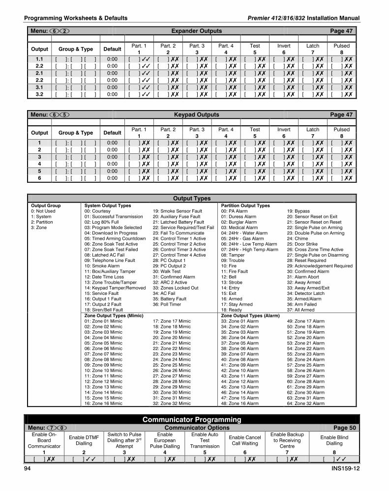
Programming Worksheets & Defaults Premier 412/816/832 Installation Manual
94 INS159-12
Menu: Expander Outputs Page 47
Output Group & Type Default Part. 1 Part. 2 Part. 3 Part. 4 Test Invert Latch Pulsed
1 2 3 4 5 6 7 8 1.1 [ ]: [ ] [ ] 0:00 [ ] [ ] [ ] [ ] [ ] [ ] [ ] [ ] 2.2 [ ]: [ ] [ ] 0:00 [ ] [ ] [ ] [ ] [ ] [ ] [ ] [ ] 2.1 [ ]: [ ] [ ] 0:00 [ ] [ ] [ ] [ ] [ ] [ ] [ ] [ ] 2.2 [ ]: [ ] [ ] 0:00 [ ] [ ] [ ] [ ] [ ] [ ] [ ] [ ] 3.1 [ ]: [ ] [ ] 0:00 [ ] [ ] [ ] [ ] [ ] [ ] [ ] [ ] 3.2 [ ]: [ ] [ ] 0:00 [ ] [ ] [ ] [ ] [ ] [ ] [ ] [ ]
Menu: Keypad Outputs Page 47
Output Group & Type Default Part. 1 Part. 2 Part. 3 Part. 4 Test Invert Latch Pulsed
1 2 3 4 5 6 7 8 1 [ ]: [ ] [ ] 0:00 [ ] [ ] [ ] [ ] [ ] [ ] [ ] [ ] 2 [ ]: [ ] [ ] 0:00 [ ] [ ] [ ] [ ] [ ] [ ] [ ] [ ] 3 [ ]: [ ] [ ] 0:00 [ ] [ ] [ ] [ ] [ ] [ ] [ ] [ ] 4 [ ]: [ ] [ ] 0:00 [ ] [ ] [ ] [ ] [ ] [ ] [ ] [ ] 5 [ ]: [ ] [ ] 0:00 [ ] [ ] [ ] [ ] [ ] [ ] [ ] [ ] 6 [ ]: [ ] [ ] 0:00 [ ] [ ] [ ] [ ] [ ] [ ] [ ] [ ]
Output Types Output Group 0: Not Used 1: System 2: Partition 3: Zone
System Output Types 00: Courtesy 01: Successful Transmission 02: Log 80% Full 03: Program Mode Selected 04: Download In Progress 05: Timed Arming Countdown 06: Zone Soak Test Active 07: Zone Soak Test Failed 08: Latched AC Fail 09: Telephone Line Fault 10: Smoke Alarm 11: Box/Auxiliary Tamper 12: Date Time Loss 13: Zone Trouble/Tamper 14: Keypad Tamper/Removed 15: Service Fault 16: Output 1 Fault 17: Output 2 Fault 18: Siren/Bell Fault
19: Smoke Sensor Fault 20: Auxiliary Fuse Fault 21: Latched Battery Fault 22: Service Required/Test Fail 23: Fail To Communicate 24: Control Timer 1 Active 25: Control Timer 2 Active 26: Control Timer 3 Active 27: Control Timer 4 Active 28: PC Output 1 29: PC Output 2 30: Walk Test 31: Confirmed Alarm 32: ARC 2 Active 33: Zones Locked Out 34: AC Fail 35: Battery Fault 36: Poll Timer
Partition Output Types 00: PA Alarm 01: Duress Alarm 02: Burglar Alarm 03: Medical Alarm 04: 24Hr - Water Alarm 05: 24Hr - Gas Alarm 06: 24Hr - Low Temp Alarm 07: 24Hr - High Temp Alarm 08: Tamper 09: Trouble 10: Fire 11: Fire Fault 12: Bell 13: Strobe 14: Entry 15: Exit 16: Armed 17: Stay Armed 18: Ready
19: Bypass 20: Sensor Reset on Exit 21: Sensor Reset on Reset 22: Single Pulse on Arming 23: Double Pulse on Arming 24: Chime 25: Door Strike 26: Cross Zone Time Active 27: Single Pulse on Disarming 28: Reset Required 29: Acknowledgement Required 30: Confirmed Alarm 31: Alarm Abort 32: Away Armed 33: Away Armed/Exit 34: Detector Latch 35: Armed/Alarm 36: Arm Failed 37: All Armed
Zone Output Types (Mimic) 01: Zone 01 Mimic 02: Zone 02 Mimic 03: Zone 03 Mimic 04: Zone 04 Mimic 05: Zone 05 Mimic 06: Zone 06 Mimic 07: Zone 07 Mimic 08: Zone 08 Mimic 09: Zone 09 Mimic 10: Zone 10 Mimic 11: Zone 11 Mimic 12: Zone 12 Mimic 13: Zone 13 Mimic 14: Zone 14 Mimic 15: Zone 15 Mimic 16: Zone 16 Mimic
17: Zone 17 Mimic 18: Zone 18 Mimic 19: Zone 19 Mimic 20: Zone 20 Mimic 21: Zone 21 Mimic 22: Zone 22 Mimic 23: Zone 23 Mimic 24: Zone 24 Mimic 25: Zone 25 Mimic 26: Zone 26 Mimic 27: Zone 27 Mimic 28: Zone 28 Mimic 29: Zone 29 Mimic 30: Zone 30 Mimic 31: Zone 31 Mimic 32: Zone 32 Mimic
Zone Output Types (Alarm) 33: Zone 01 Alarm 34: Zone 02 Alarm 35: Zone 03 Alarm 36: Zone 04 Alarm 37: Zone 05 Alarm 38: Zone 06 Alarm 39: Zone 07 Alarm 40: Zone 08 Alarm 41: Zone 09 Alarm 42: Zone 10 Alarm 43: Zone 11 Alarm 44: Zone 12 Alarm 45: Zone 13 Alarm 46: Zone 14 Alarm 47: Zone 15 Alarm 48: Zone 16 Alarm
49: Zone 17 Alarm 50: Zone 18 Alarm 51: Zone 19 Alarm 52: Zone 20 Alarm 53: Zone 21 Alarm 54: Zone 22 Alarm 55: Zone 23 Alarm 56: Zone 24 Alarm 57: Zone 25 Alarm 58: Zone 26 Alarm 59: Zone 27 Alarm 60: Zone 28 Alarm 61: Zone 29 Alarm 62: Zone 30 Alarm 63: Zone 31 Alarm 64: Zone 32 Alarm
Communicator Programming Menu: Communicator Options Page 50
Enable On-Board
Communicator
Enable DTMF Dialling
Switch to Pulse Dialling after 3rd
Attempt
Enable European
Pulse Dialling
Enable Auto Test
Transmission
Enable Cancel Call Waiting
Enable Backup to Receiving
Centre
Enable Blind Dialling
1 2 3 4 5 6 7 8 [ ] [ ] [ ] [ ] [ ] [ ] [ ] [ ]
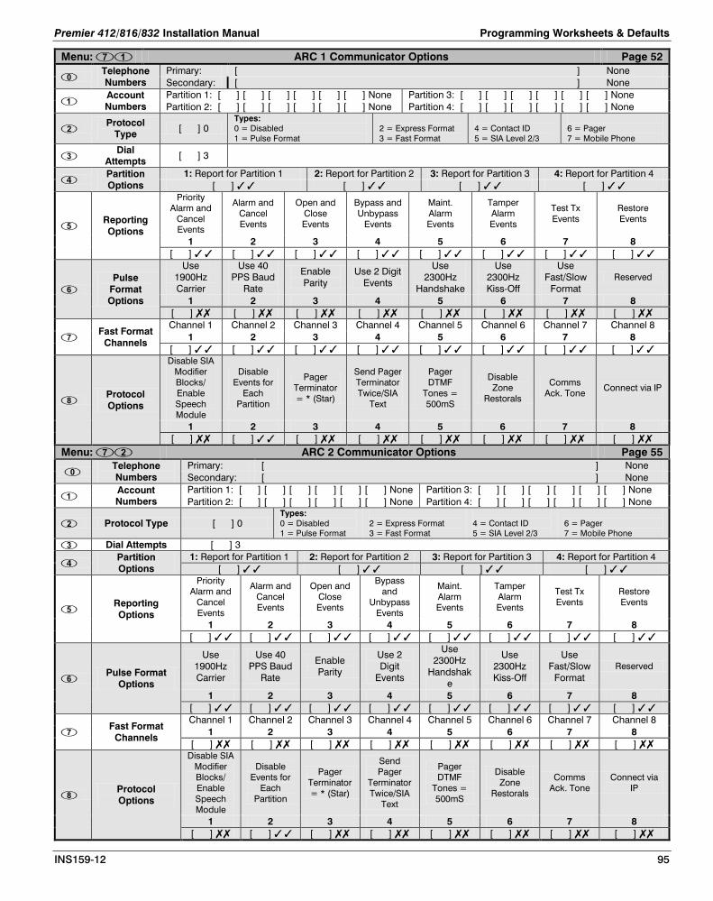
Premier 412/816/832 Installation Manual Programming Worksheets & Defaults
INS159-12 95
Menu: ARC 1 Communicator Options Page 52
Telephone Numbers
Primary: [ ] None Secondary: [ ] None
Account Numbers
Partition 1: [ ] [ ] [ ] [ ] [ ] [ ] None Partition 3: [ ] [ ] [ ] [ ] [ ] [ ] None Partition 2: [ ] [ ] [ ] [ ] [ ] [ ] None Partition 4: [ ] [ ] [ ] [ ] [ ] [ ] None
Protocol
Type [ ] 0 Types: 0 = Disabled 1 = Pulse Format
2 = Express Format 3 = Fast Format
4 = Contact ID 5 = SIA Level 2/3
6 = Pager 7 = Mobile Phone
Dial
Attempts [ ] 3
Partition Options
1: Report for Partition 1 2: Report for Partition 2 3: Report for Partition 3 4: Report for Partition 4 [ ] [ ] [ ] [ ]
Reporting Options
Priority Alarm and
Cancel Events
Alarm and Cancel Events
Open and Close Events
Bypass and Unbypass
Events
Maint. Alarm Events
Tamper Alarm Events
Test Tx Events
Restore Events
1 2 3 4 5 6 7 8 [ ] [ ] [ ] [ ] [ ] [ ] [ ] [ ]
Pulse
Format Options
Use 1900Hz Carrier
Use 40 PPS Baud
Rate
Enable Parity
Use 2 Digit Events
Use 2300Hz
Handshake
Use 2300Hz Kiss-Off
Use Fast/Slow
Format Reserved
1 2 3 4 5 6 7 8 [ ] [ ] [ ] [ ] [ ] [ ] [ ] [ ]
Fast Format
Channels
Channel 1 Channel 2 Channel 3 Channel 4 Channel 5 Channel 6 Channel 7 Channel 8 1 2 3 4 5 6 7 8
[ ] [ ] [ ] [ ] [ ] [ ] [ ] [ ]
Protocol Options
Disable SIA Modifier Blocks/ Enable Speech Module
Disable Events for
Each Partition
Pager Terminator = * (Star)
Send Pager Terminator Twice/SIA
Text
Pager DTMF
Tones = 500mS
Disable Zone
Restorals
Comms Ack. Tone
Connect via IP
1 2 3 4 5 6 7 8 [ ] [ ] [ ] [ ] [ ] [ ] [ ] [ ]
Menu: ARC 2 Communicator Options Page 55
Telephone Numbers
Primary: [ ] None Secondary: [ ] None
Account Numbers
Partition 1: [ ] [ ] [ ] [ ] [ ] [ ] None Partition 3: [ ] [ ] [ ] [ ] [ ] [ ] None Partition 2: [ ] [ ] [ ] [ ] [ ] [ ] None Partition 4: [ ] [ ] [ ] [ ] [ ] [ ] None
Protocol Type [ ] 0 Types: 0 = Disabled 1 = Pulse Format
2 = Express Format 3 = Fast Format
4 = Contact ID 5 = SIA Level 2/3
6 = Pager 7 = Mobile Phone
Dial Attempts [ ] 3
Partition Options
1: Report for Partition 1 2: Report for Partition 2 3: Report for Partition 3 4: Report for Partition 4 [ ] [ ] [ ] [ ]
Reporting Options
Priority Alarm and
Cancel Events
Alarm and Cancel Events
Open and Close Events
Bypass and
Unbypass Events
Maint. Alarm Events
Tamper Alarm Events
Test Tx Events
Restore Events
1 2 3 4 5 6 7 8 [ ] [ ] [ ] [ ] [ ] [ ] [ ] [ ]
Pulse Format
Options
Use 1900Hz Carrier
Use 40 PPS Baud
Rate
Enable Parity
Use 2 Digit
Events
Use 2300Hz
Handshake
Use 2300Hz Kiss-Off
Use Fast/Slow
Format Reserved
1 2 3 4 5 6 7 8 [ ] [ ] [ ] [ ] [ ] [ ] [ ] [ ]
Fast Format
Channels
Channel 1 Channel 2 Channel 3 Channel 4 Channel 5 Channel 6 Channel 7 Channel 8 1 2 3 4 5 6 7 8
[ ] [ ] [ ] [ ] [ ] [ ] [ ] [ ]
Protocol Options
Disable SIA Modifier Blocks/ Enable Speech Module
Disable Events for
Each Partition
Pager Terminator = * (Star)
Send Pager
Terminator Twice/SIA
Text
Pager DTMF
Tones = 500mS
Disable Zone
Restorals
Comms Ack. Tone
Connect via IP
1 2 3 4 5 6 7 8 [ ] [ ] [ ] [ ] [ ] [ ] [ ] [ ]

Programming Worksheets & Defaults Premier 412/816/832 Installation Manual
96 INS159-12
Menu: Fast Format Restore Channels Page 55 Channel 1 Channel 2 Channel 3 Channel 4 Channel 5 Channel 6 Channel 7 Channel 8
1 2 3 4 5 6 7 8 [ ] [ ] [ ] [ ] [ ] [ ] [ ] [ ]
Menu: Fast Format Open/Close Channels Page 56 Channel 1 Channel 2 Channel 3 Channel 4 Channel 5 Channel 6 Channel 7 Channel 8
1 2 3 4 5 6 7 8 [ ] [ ] [ ] [ ] [ ] [ ] [ ] [ ]
Menu: Cancel Call Waiting Sequence Page 54 Cancel Call Waiting Sequence: [ ] None
Download Programming Menu: Download Menu Options Page 60
Download Options
Enable Attended Download
Enable Unattended Call
Back
Enable 2-Call Answer Phone
Defeat
Restrict Download when
Armed
Download when Part Armed
Disconnect Telephone
Line 1 2 3 4 5 6
[ ] [ ] [ ] [ ] [ ] [ ]
Download Tel No [ ] None
Download Password [ ] [ ] [ ] [ ] [ ] [ ] [ ] [ ] None
Dial Attempts [ ] 1 Ring Count [ ] 2
Com1 Device Type [ ] 0 Types: 0 = PC-Com; 1 = RadioPlus; 2 = Inovonics Radio; 3 = ComIP; 4 = WebWayOne/Emizon Module; 5 = Chiron Module
ComIP Address/Port Address: [ ] . [ ] . [ ] . [ ] Port: [ ] [ ] [ ] [ ] [ ] None ComIP Gateway [ ] . [ ] . [ ] . [ ] None ComIP Subnet Mask [ ] 8
Com 2 Device Type [ ] 0 Types: 0 = PC-Com; 1 = RadioPlus; 2 = Inovonics Radio; 3 = ComIP; 4 = WebWayOne/Emizon Module; 5 = Chiron Module
Chiron Iris Setup [ ] 0 Options: 1 = Access Point Name; 2 = User Name; 3 = Password;
Reporting Codes Programming Menu: Zone Alarm/Restore Codes Page 63 Menu: Zone Bypass/Unbypass Codes Page 63
Zone Event No Alarm Code Event No Restore Code Event No Bypass Code Event No Unbypass Code
01 00 [ ] [ ] 31 01 [ ] [ ] 00 00 [ ] [ ] 61 01 [ ] [ ] 00 02 02 [ ] [ ] 32 03 [ ] [ ] 00 02 [ ] [ ] 62 03 [ ] [ ] 00 03 04 [ ] [ ] 33 05 [ ] [ ] 00 04 [ ] [ ] 63 05 [ ] [ ] 00 04 06 [ ] [ ] 34 07 [ ] [ ] 00 06 [ ] [ ] 64 07 [ ] [ ] 00 05 08 [ ] [ ] 35 09 [ ] [ ] 00 08 [ ] [ ] 65 09 [ ] [ ] 00 06 10 [ ] [ ] 36 11 [ ] [ ] 00 10 [ ] [ ] 66 11 [ ] [ ] 00 07 12 [ ] [ ] 37 13 [ ] [ ] 00 12 [ ] [ ] 67 13 [ ] [ ] 00 08 14 [ ] [ ] 38 15 [ ] [ ] 00 14 [ ] [ ] 68 15 [ ] [ ] 00 09 16 [ ] [ ] 39 17 [ ] [ ] 00 16 [ ] [ ] 69 17 [ ] [ ] 00 10 18 [ ] [ ] 3A 19 [ ] [ ] 00 18 [ ] [ ] 6A 19 [ ] [ ] 00 11 20 [ ] [ ] 3B 21 [ ] [ ] 00 20 [ ] [ ] 6B 21 [ ] [ ] 00 12 22 [ ] [ ] 3C 23 [ ] [ ] 00 22 [ ] [ ] 6C 23 [ ] [ ] 00 13 24 [ ] [ ] 3D 25 [ ] [ ] 00 24 [ ] [ ] 6D 25 [ ] [ ] 00 14 26 [ ] [ ] 3E 27 [ ] [ ] 00 26 [ ] [ ] 6E 27 [ ] [ ] 00 15 28 [ ] [ ] 3F 29 [ ] [ ] 00 28 [ ] [ ] 6F 29 [ ] [ ] 00 16 30 [ ] [ ] 30 31 [ ] [ ] 00 30 [ ] [ ] 60 31 [ ] [ ] 00 17 32 [ ] [ ] 00 33 [ ] [ ] 00 32 [ ] [ ] 00 33 [ ] [ ] 00 18 34 [ ] [ ] 00 35 [ ] [ ] 00 34 [ ] [ ] 00 35 [ ] [ ] 00 19 36 [ ] [ ] 00 37 [ ] [ ] 00 36 [ ] [ ] 00 37 [ ] [ ] 00 20 38 [ ] [ ] 00 39 [ ] [ ] 00 38 [ ] [ ] 00 39 [ ] [ ] 00 21 40 [ ] [ ] 00 41 [ ] [ ] 00 40 [ ] [ ] 00 41 [ ] [ ] 00 22 42 [ ] [ ] 00 43 [ ] [ ] 00 42 [ ] [ ] 00 43 [ ] [ ] 00 23 44 [ ] [ ] 00 45 [ ] [ ] 00 44 [ ] [ ] 00 45 [ ] [ ] 00 24 46 [ ] [ ] 00 47 [ ] [ ] 00 46 [ ] [ ] 00 47 [ ] [ ] 00 25 48 [ ] [ ] 00 49 [ ] [ ] 00 48 [ ] [ ] 00 49 [ ] [ ] 00 26 50 [ ] [ ] 00 51 [ ] [ ] 00 50 [ ] [ ] 00 51 [ ] [ ] 00 27 52 [ ] [ ] 00 53 [ ] [ ] 00 52 [ ] [ ] 00 53 [ ] [ ] 00

Premier 412/816/832 Installation Manual Programming Worksheets & Defaults
INS159-12 97
Reporting Codes Programming 28 54 [ ] [ ] 00 55 [ ] [ ] 00 54 [ ] [ ] 00 55 [ ] [ ] 00 29 56 [ ] [ ] 00 57 [ ] [ ] 00 56 [ ] [ ] 00 57 [ ] [ ] 00 30 58 [ ] [ ] 00 59 [ ] [ ] 00 58 [ ] [ ] 00 59 [ ] [ ] 00 31 60 [ ] [ ] 00 61 [ ] [ ] 00 60 [ ] [ ] 00 61 [ ] [ ] 00 32 62 [ ] [ ] 00 63 [ ] [ ] 00 62 [ ] [ ] 00 63 [ ] [ ] 00
Menu: Non Zone Alarm/Restore Codes Page 63 Event No Event Type Event Reporting Group Pulse/Express Contact ID SIA
00 AC Fail Alarm Maintenance [ ] [ ] FF 301 AT 01 Restore Restore [ ] [ ] AF 301 AR 02 Low Battery Alarm Maintenance [ ] [ ] FE 302 YT 03 Restore Restore [ ] [ ] AE 302 YR 04 Telephone Line Fault Alarm Maintenance [ ] [ ] FD 351 LT 05 Restore Restore [ ] [ ] AD 351 LR 06 Fail to Communicate Alarm Maintenance [ ] [ ] 00 354 YC 07 Restore - - - - 08 Open/Close Alarm Open [ ] [ ] B* 401 OP 09 Restore Close [ ] [ ] C* 401 CL 10 Recent Closing Alarm Close [ ] [ ] DA 459 CR 11 Restore - - - - 12 Auto Open/Close Alarm Open [ ] [ ] CC 403 OA 13 Restore Close [ ] [ ] CC 403 CA 14 Auto Arm Deferred Alarm Close [ ] [ ] D* 405 CE 15 Restore - - - - 16 Remote Open/Close Alarm Open [ ] [ ] B9 407 OP 17 Restore Close [ ] [ ] C9 407 CL 18 Quick Arm Alarm - - - 19 Restore Close [ ] [ ] C 408 CL 20 Open After Alarm (Cancel) Alarm Open [ ] [ ] D* 406 OR 21 Restore - - - - 22 Download Start Alarm Maintenance [ ] [ ] 00 23 Restore - - - - 24 Download End Alarm Maintenance [ ] [ ] 00 25 Restore - - - - 26 Group Bypass/Unbypass Alarm Bypass [ ] [ ] 00 574 27 Restore Unbypass [ ] [ ] 00 574 28 Log Capacity Alert (80%) Alarm Maintenance [ ] [ ] 00 623 JL 29 Restore - - - - 30 Keypad Lockout (Device No) Alarm Tamper [ ] [ ] EA 421 JA 31 Restore - - - - 32 Code Tamper Alarm (Device No) Alarm Tamper [ ] [ ] EA 421 JA 33 Restore - - - - 34 Manual Test Transmission Alarm Test [ ] [ ] 9A 601 RX 35 Restore - - - - 36 Automatic Test Transmission Alarm Test [ ] [ ] 9C 602 RP 37 Restore - - - - 38 User Zone Test Start/End Alarm Test [ ] [ ] 00 39 Restore Restore [ ] [ ] 00 40 Auxiliary Power Fail/Restore Alarm Maintenance [ ] [ ] FB 300 YP 41 Restore Restore [ ] [ ] AB 300 YQ 42 Bell Output Fault/Restore Alarm Maintenance [ ] [ ] 00 321 YA 43 Restore Restore [ ] [ ] 00 321 YH 44 Installer Programming Start Alarm Maintenance [ ] [ ] 00 45 Restore - - - - 46 Installer Programming End Alarm Maintenance [ ] [ ] 00 47 Restore - - - - 48 Exit Error Alarm Close [ ] [ ] 00 49 Restore - - - - 50 Verified Cross Zone Alarm Alarm Alarm [ ] [ ] 00 140 BV 51 Restore - - - - 52 Soak Test Alarm Test [ ] [ ] 00 53 Restore - - - - 54 Fire Zone Trouble Alarm Tamper [ ] [ ] 00 373 FT

Programming Worksheets & Defaults Premier 412/816/832 Installation Manual
98 INS159-12
Menu: Non Zone Alarm/Restore Codes Page 63 Event No Event Type Event Reporting Group Pulse/Express Contact ID SIA
55 Restore Restore [ ] [ ] 00 373 FJ 56 System Power Up Alarm Maintenance [ ] [ ] 00 57 Restore - - - - 58 Swinger Shutdown (Zone No) Alarm Alarm [ ] [ ] 00 59 Restore - - - - 60 User Code Entered Alarm - - - - 61 Restore - - - - 62 Exit Started Alarm - - - - 63 Restore - - - - 64 Entry Started Alarm - - - - 65 Restore - - - - 66 Bell Active Alarm - - - - 67 Restore - - - - 68 Alarm Active Alarm - - - - 69 Restore - - - - 70 Keypad Tamper Alarm Tamper [ ] [ ] 3* 137 TA 71 Restore - - - - 72 Keypad Medical Alarm Priority Alarm [ ] [ ] 00 100 MA 73 Restore - - - - 74 Keypad Fire/2-Wire Smoke Alarm Priority Alarm [ ] [ ] 00 115 FA 75 Restore Restore [ ] [ ] 00 115 FH 76 Duress Code Alarm Alarm Priority Alarm [ ] [ ] 00 121 HA 77 Restore - - - - 78 Keypad Silent PA Alarm Priority Alarm [ ] [ ] 2* 122 PA 79 Restore - - - - 80 Keypad Audible PA/Auxiliary PA Alarm Priority Alarm [ ] [ ] 2* 120 PA 81 Restore Restore [ ] [ ] 00 120 PH 82 Box Tamper Alarm Tamper [ ] [ ] 30 137 TA 83 Restore Restore [ ] [ ] 00 137 TR 84 Zone Tamper Alarm Tamper [ ] [ ] 3* 144 TA 85 Restore Restore [ ] [ ] 00 144 TR 86 Zone Trouble Alarm Tamper [ ] [ ] 00 380 UT 87 Restore Restore [ ] [ ] 00 380 UJ 88 Expander/Remote Trouble Alarm Tamper [ ] [ ] 00 333 ET 89 Restore - - - - 90 Auxiliary Tamper Input Alarm Tamper [ ] [ ] 30 137 TA 91 Restore Restore [ ] [ ] 00 137 TR 92 Date Changed Alarm Maintenance [ ] [ ] 00 625 JD 93 Restore - - - - 94 Time Changed Alarm Maintenance [ ] [ ] 00 625 JT 95 Restore - - - - 96 System Reset Alarm Maintenance [ ] [ ] 00 97 Restore - - - - 98 Remote Control Alarm Test [ ] [ ] 00 - - 99 Restore Restore [ ] [ ] 00 - -
100 Confirmed Alarm Alarm Alarm [ ] [ ] 00 139 BV 101 Restore - - - - 102 Monitored Alarm Alarm Alarm [ ] [ ] 00 220 BA 103 Restore Restore [ ] [ ] 00 220 BH 104 FOB Low Battery Alarm Maintenance [ ] [ ] 00 384 XT 105 Restore - [ ] [ ] 00 - - 106 Radio Supervision Alarm Maintenance [ ] [ ] 00 355 YS 107 Radio Supervision Restore Maintenance [ ] [ ] 00 - YT 108 Communication Port Alarm Maintenance [ ] [ ] 00 356 ET 109 Restore - [ ] [ ] 00 - -
* If the second digit for Pulse/Express is programmed as “0”, the panel will replace this digit with the Zone/User/Keypad number.
A dash (-) indicates an event that is not generated by the control panel and therefore cannot be reported.

Premier 412/816/832 Installation Manual Notes
INS159-12 99
Notes

Texecom Limited, Bradwood Court, St. Crispin Way, Haslingden, Lancashire BB4 4PW, England.
Technical Support:
UK Customers Tel: 08456 300 600 (Calls charged at 3.36 pence per minute from a BT landline. Calls from other networks may vary.)
International Customers Tel: +44 1706 233875
Email: [email protected]
© Texecom Limited 2015
INS159-12
System Overview
Installation
Control Panel PCB Layout
Installing Remote Keypads & Expanders
Zone Connections
Siren/Bell, Telephone and Panel Outputs
Commissioning & Troubleshooting
Programming Menus
Programming Zones
Programming Partitions
Programming Global Options
Programming Remote Keypads
Programming Remote Expanders
Programming System Outputs
Programming the Communicator
Programming Download Options
Programming Reporting Codes
Programming Users
System Tests, Utilities and Using RadioPlus
Operating the Alarm System
Specifications
Quick Reference Guide & Defaults