Embed Size (px)
Citation preview
a VOLKSWAGEN
Release 5.06.02
Installation Manual
2017/07/03
rvsMVS Installation Manual Contents
This documentation is valid for rvsMVS release 05 For rvsMVS the following documentations are provided: rvsMVS Benutzer Handbuch (German)
Manual for rvs Users rvsMVS User Manual (English) Manual for rvs Users rvsMVS Operator Handbuch (German)
Manual for rvs Operator rvsMVS Operation Manual (English)
Manual for rvs Operator rvsMVS Messages and Codes (English) Overview about rvsMVS messages and abend codes Distribution information will be given kindly: T-Systems Enterprise Services GmbH Corporate Customers Silke Peigert Vertriebsassistenz - rvs Holzhauser Str. 4-8 13509 Berlin Tel. +49-30-8353-23089 Fax +49-30-8353-84869 Email mailto:[email protected] Technical information will be given kindly: T-Systems Enterprise Services GmbH rvs Systems Holzhauser Str. 4-8 13509 Berlin Tel. +49-30-3997-1777 (International) Tel. 0800-664-7745 (Germany only) Fax +49-30-8353-84869 Email mailto:[email protected] © Copyright 2017 by Volkswagen AG / T-Systems
rvsMVS Installation Manual Contents
Contents
1. Introduction ................................................................................................................. 7
2. Installation Requirements ........................................................................................ 11
2.1. Software Requirements .................................................................................................. 11
2.2. Hardware Requirements ................................................................................................. 11
2.3. License key ...................................................................................................................... 12
3. Generations, Definitions within Operating System and Control Unit ................... 13
3.1. Definition for BSC component of rvs ............................................................................ 13 3.1.1. BSC lines without autodial function .................................................................... 13 3.1.2. BSC lines with autodial function (Interface V.25) ............................................... 14 3.1.3. BSC lines with autodial function (Interface V.25bis) .......................................... 16
3.2. Definitions for SNA component of rvs .......................................................................... 17
3.3. Definitions for X25 component of rvs ........................................................................... 19 3.3.1. Definitions for using the X.25 network via XOT ................................................. 19 3.3.2. Definitions for using the X.25 network via NPSI ................................................ 19 3.3.3. Definitions for using the ISDN network .............................................................. 23
3.4. Definitions for the SNA LU6.2 component of rvs ......................................................... 25
3.5. Definitions for TCP/IP component of rvs ...................................................................... 26
3.6. Definitions for FTP component of rvs and rvsLight .................................................... 26
3.7. Definitions for rvsWIN stations ...................................................................................... 29
3.8. Definitions for remote operating function .................................................................... 29
4. rvs System Files ........................................................................................................ 31
4.1. rvs Load Library .............................................................................................................. 31
4.2. rvs Control dataset .......................................................................................................... 31
4.3. rvs Log dataset ................................................................................................................ 32
4.4. rvs Tables Dataset ........................................................................................................... 32
4.5. rvs Key Data data set ...................................................................................................... 32
4.6. Datasets for USP feature only ........................................................................................ 33
4.7. rvs Jobs Dataset .............................................................................................................. 33
4.8. rvs EXEC Dataset ............................................................................................................ 33
5. Steps for installation of rvsMVS .............................................................................. 34
5.1. Installation Guide from the Compact Disk .................................................................... 34
5.2. Content of Compact Disk: .............................................................................................. 35
5.3. Creation of module DF067A - Macro rvsDYN ............................................................... 36
5.4. Change of dataset names within Tables file ................................................................. 38
5.5. Creation of rvs Control Dataset ..................................................................................... 38
5.6. Creation of rvs Log Dataset............................................................................................ 39
5.7. Modification of the rvs Tables file ................................................................................. 39
5.8. Installation of the rvs ISPF panels ................................................................................. 40
5.9. Creation of rvs Key Data dataset ................................................................................... 44
rvsMVS Installation Manual Contents
5.10. Installation of the Security Library Data dataset .......................................................... 44
6. Description of the Tables Dataset ........................................................................... 46
6.1. rvs Start Parameter ......................................................................................................... 46 6.1.1. Example for definitions to support more X.25 multi channel links ..................... 69
6.2. rvs Stations Table ............................................................................................................ 72 6.2.0. Subset 0 (general parameters valid for all stations) .......................................... 74 6.2.1. Subset 1 (valid for BSC Entries) ........................................................................ 84 6.2.2. Subset 2 (valid for SNA Entries) ........................................................................ 90 6.2.3. Subset 3 (valid for station entries using ODETTE FTP) .................................... 94 6.2.4. Subset 4 (valid for X.25/XOT Direct Entries) ..................................................... 98 6.2.5. Subset 5 (valid for LU 6.2 stations) .................................................................. 102 6.2.6. Subset 6 (valid for TCP/IP Direct Entries) ........................................................ 106 6.2.7. Subset 7 (valid for FTP stations) ...................................................................... 108 6.2.8. Subset 8 (valid for Indirect Stations = VIA entries) .......................................... 112 6.2.9. Subset 9 (valid for BSC Line Entries) .............................................................. 114 6.2.10. Examples of a Stations Table .......................................................................... 119
6.3. Special Transmission Protocols (rvs Program Profile Table) .................................. 123
6.4. Definition of rvs Sessions Table .................................................................................. 125
6.5. JCL Member for Copy Jobs .......................................................................................... 129
6.6. Control of rvs Messages ............................................................................................... 133 6.6.1. Control of Messages for Console and remote Operating ................................ 133 6.6.2. Additional SYSOUT protocols .......................................................................... 135 6.6.3. Definition of "non-deletable" messages ........................................................... 136
6.7. Automatically executed rvs commands ...................................................................... 137
6.8. RMOP PF Keys ............................................................................................................... 139
6.9. rvs Procedures and JOBS ............................................................................................ 141 6.9.1. rvs Start Procedure .......................................................................................... 141 6.9.2. Overview on rvs Transmissions ....................................................................... 143 6.9.2.1. PDF0002A (obsolete) ....................................................................................... 143 6.9.2.2. DF078B ............................................................................................................ 143 6.9.3. Deleting old entries from the rvs Control Dataset ............................................ 146 6.9.4. Saving and Recovery of the rvs Control dataset.............................................. 147
6.10. JCL Member for failing automatic Job start ............................................................... 151
6.11. Code Translation ........................................................................................................... 153
7. Running Installation Tests ..................................................................................... 156
7.1. Start of rvs Monitor (Procedure PDF0001A - Alias MONITOR) ................................. 156
7.2. Transmission of Datasets ............................................................................................. 159
8. Special Functions (Procedures) ............................................................................ 160
8.1. Using BSC Line(s) as Backup for SNA ........................................................................ 160
8.2. rvs Trace ......................................................................................................................... 160 8.2.1. Trace Output .................................................................................................... 161 8.2.2. Start and Stop of rvs Trace .............................................................................. 162 8.2.3. Format of BTAM Trace (BSC lines) ................................................................. 163 8.2.4. Format of VTAM Trace (SNA sessions) ........................................................... 165 8.2.5. Format of LU6.2 Trace ..................................................................................... 167 8.2.6. Format of TCP/IP Trace ................................................................................... 169 8.2.7. Format of FTP Trace ........................................................................................ 171
9. rvs Features ............................................................................................................. 174
rvsMVS Installation Manual Contents
9.1. Feature Architecture ..................................................................................................... 174
9.2. Partioned Data Set (PDS) Transfer .............................................................................. 175
9.3. External Compression .................................................................................................. 176 9.3.1. 2 Steps to Prepare the Use of External Compress Feature ............................ 176
9.4. External Security ........................................................................................................... 177 9.4.1. 7 Steps to Prepare the Use of External Security Feature ................................ 177
10. OFTP 2 Features ...................................................................................................... 179
10.1. Introduction .................................................................................................................... 179
10.2. Steps to configure required datasets (BUILTIN KEY/CERTSTORE) ........................ 179 10.2.1. Key store .......................................................................................................... 179 10.2.2. Certificate store ................................................................................................ 185 10.2.3. Certificate management parameter ................................................................. 189
10.3. Steps to configure RACF access (RACF KEY/CERTSTORE) .................................... 190 10.3.1. Examples.......................................................................................................... 190
10.4. Configuration of OFTP2 Features ................................................................................ 195 10.4.1. rvs Start Parameter (CNTL member) ............................................................... 195 10.4.2. OFTP2 enabled station (STATIONS member) ................................................ 197 10.4.3. Language environment option file CEEOPTS.................................................. 201
10.5. Configuration of the rvsMVS start procedure ............................................................ 202
10.6. System messages and error codes ............................................................................. 202
10.7. AT-TLS ............................................................................................................................ 203 10.7.1. General ............................................................................................................. 203 10.7.2. Sample Configuration Step by Step ................................................................. 203
10.8. Annex: User exit DF053R for implementation of randomizing ................................. 209
11. Appendix .................................................................................................................. 216
A. rvs User Exits .......................................................................................................... 216
A.1. Authorization Exit DFUX001 ......................................................................................... 216
A.2. rvsWIN Exit DFUX002 .................................................................................................... 222
A.3. Accounting User Exit .................................................................................................... 224
A.4. Job Submit Exit DFUX003............................................................................................. 225
A.5. Identification User Exit .................................................................................................. 228
A.6. ODETTE FTP User Exits ................................................................................................ 232
B. Description of the rvs control record (KDRECORD) ............................................ 235
C. Description of accounting information ................................................................. 238
D. rvs statistics ............................................................................................................ 240
D.1. General Information ...................................................................................................... 240
D.2. Prerequisites .................................................................................................................. 240
D.3. Job to gain the basic data for the statistics ............................................................... 240
D.4. Station Activity Program ............................................................................................... 241
D.5. Line Activity Program ................................................................................................... 244
D.6. Legend of rvs statistics ................................................................................................ 245

rvsMVS Installation Manual Contents
E. Example for an extended rvs Start Procedure ...................................................... 248
F. Reference Utility (program DF076A) ...................................................................... 250
G. Using the 'Remote Operating Function' ................................................................ 268
H. rvsMVS Tables ......................................................................................................... 272
H.1. rvsMVS Program Profile Table (only used for the BSC component) ....................... 272
I. Key Data Utility (Program DF054K) ....................................................................... 276
I.1. Introduction .................................................................................................................... 276
I.2. rvs Key Data dataset ..................................................................................................... 276
I.3. Maintenance of the key management .......................................................................... 276 I.3.1. Overview .......................................................................................................... 276 I.3.2. Creation of rvs Key Data dataset ..................................................................... 276 I.3.3. Initialize Key Datasets (VSAM) ........................................................................ 277 I.3.4. Generate a key pair of your own ...................................................................... 277 I.3.5. Import your own key pair to the key management ........................................... 277 I.3.6. Import a public key of your partner .................................................................. 278 I.3.7. List all keys of the key management ................................................................ 278 I.3.8. Export all keys from the key management to a sequential file ......................... 278 I.3.9. Import keys from a sequential file to the key management ............................. 279 I.3.10. Delete key from the key management ............................................................. 279
I.4. Detailed description of function Key Data Utility (Program DF054K) ...................... 279 I.4.1. Function GENKEYS ......................................................................................... 280 I.4.2. Function KEYS ................................................................................................. 281 I.4.3. Function LIST ................................................................................................... 282 I.4.4. Function EXPT ................................................................................................. 282 I.4.5. Function IMPT .................................................................................................. 282 I.4.6. Function ADMN ................................................................................................ 283
I.5. Return codes of DF054K ............................................................................................... 284
I.6. DF054K Messages: ........................................................................................................ 285
I.7. Key Data record description ........................................................................................ 289
Index ............................................................................................................................... 291
rvsMVS Installation Manual 1. Introduction
1. Introduction rvsMVS is a file transfer system. Datasets can be interchanged between a computer where rvsMVS is installed and other computers where rvsMVS or other (rvs compatible) products are installed (see below).
The rvs software allows transmitting any sequential or partitioned dataset (independent of record length, block length and record format) from one computer to another, whilst the completeness and correctness of the transmission are monitored by the software. Restrictions for the datasets to be transmitted may exist if the remote side has not installed rvsMVS. rvsMVS includes seven components for support of different line procedures: • BSC (for switched or leased BSC lines) • SNA (using the normal SNA network) Note that connections between two hosts require INN
links, this means a leased line connection) • LU 6.2 (using the normal SNA network). This component works with the "ODETTE File
Transfer Protocol". • X25 (using the X25 network). This component works with the "ODETTE File Transfer
Protocol". • X25 (using the X25 network via XOT). This component works with the "ODETTE File Transfer
Protocol". • TCP/IP. This component works with the "ODETTE File Transfer Protocol". • FTP (using the TCP/IP network). This component allows transmissions to/from any FTP
servers/clients There are different conditions for distribution of the different components of rvs rvs works as a monitor system in a separate MVS address space, independent of other products (subsystems) like CICS, IMS, TSO, JES2 or JES3. The way how datasets are transmitted or received and a set of additional monitor functions like • automatic job start after transmission of a certain dataset • automatic dial function for BSC lines, X.25, LU 6.2 and TCP/IP connections • automatic activation of BSC lines and/or SNA sessions if - for some reason - one or more of
these lines (sessions) have become inactive allow operation of rvs with a minimum of manual activities. A remote operating function allows controlling and operating from any 3270 screen. The rvs monitor normally runs for the duration of one or more days, it is not necessary to stop the monitor before or after transmissions have been executed. The rvs monitor is designed to operate with any number of BSC lines, SNA (LU 0 and LU 6.2), TCP/IP and X25 connections (switched virtual circuits). There is no restriction in view of the number of file transmissions which can be executed parallel at the same time. Allocation of the datasets to be transmitted (received) takes place dynamically, i.e. no specific job control instructions are required within the rvs start procedure.
rvsM
VS
Insta
llatio
n M
an
ual
1. In
trod
uctio
n
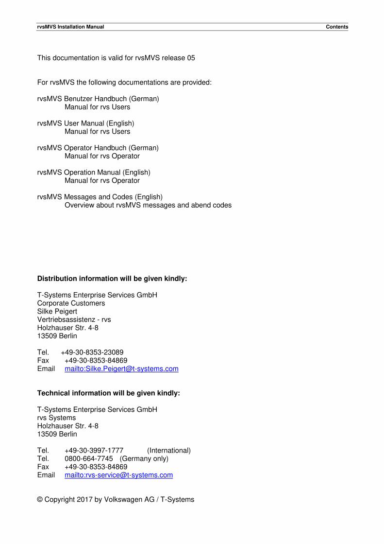
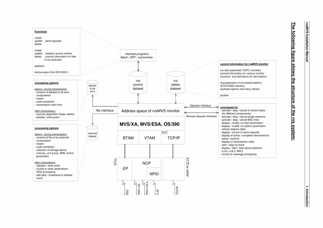
Th
e fo
llow
ing
figu
re s
ho
ws th
e s
tructu
re o
f the rv
s s
yste
m:
processing options
before / during transmission:
- rename of dataset to be sent
- compression
- restart- code translation
- transmission start time
after transmission:- execute disposition (keep, delete)
- jobstart / write event
processing options
before / during transmission:
- rename of file to be received
- compression
- restart
- code translation
- selection of storage device
(volume, unit group, SMS control
parameter)
after transmission:- Jobstart / write event
- routing to other destinations
- GDG processing- add date / timestamp to dataset
name
MVS/XA, MVS/ESA, OS/390
Address space of rvsMVS monitor
BTAM VTAM TCP/IP
NCP
EP
NPSI
BS
C
SN
A L
U0
SN
A L
U6
.2
X.2
5
TC
P/IP
Functions
createupdate send requests
delete
create
update resident receive entries
delete (control information for files
to be received)
statistics
Authorization Exit (DFUX001)
commands for- activate / stop / cancel of control tasks
(for different components)
- activate / stop / cancel single sessions
- activate / stop / cancel BSC lines
- display / modify rvs start parameters
- display / modify rvs station parameters
- refresh stations table
- display / control of send requests
- display of active / complete transmissions
(send / receive)
- display of transmission rates
- start / stop rvs trace
- display / start / stop active sessions
(LU0, LU6.2, BSC)
- control of message processing
control information for rvsMVS monitor
rvs start parameter (CNTL member)
(control information for various monitor
functions and definitions for own station)
characteristics of connected stations
(STATIONS member)
(autodial options and many others)
profiles
Operator Interface
Remote Operator Interface
rvstables
dataset
rvscontroldataset
Interface programsBatch / SPF / subroutines
file interface
datasetto besent
received
dataset
37xx
31
72
or o
the
rXOT
rvsMVS Installation Manual 1. Introduction
A central control and information file (control dataset) contains - among others - information on pending, running and terminated transmissions. This file is the interface between the rvs monitor on one side and rvs users (batch jobs, TSO sessions using the rvs ISPF panels) on the other side. Support of transmission protocols: rvsMVS supports different transmission protocols. rvs internal protocols are used as well as common file transfer protocols. • rvs internal transmission protocols rvs internal protocols are used if the remote side uses one of the following rvs products:
Product line procedure functions of transmission protocol
rvsMVS BSC, SDLC restart, vertical code compression rvs-DOS BSC restart, blank compression rvs-VSE/SNA SDLC restart, vertical code compression rvs-RPG BSC no restart, line blocking (no compression)
• rvs file transfer protocols rvsMVS supports the "ODETTE File Transfer Protocol" up to version 2.0 (RFC5024). The X25, LU6.2 and TCP/IP components of rvs support this protocol. For more service between stations with rvs® products, rvs enhances this protocol by using some specials: • rvsMVS PDS File Transfer
Use of the user fields of SSID and SFID protocol record. These fields contain some flags led by an eye catcher: RF) for initiator's outgoing protocol records and RF (for incoming protocol records.
• Additionally rvsMVS uses a SFID extension (SFIX) for transfer of partitioned data set information.
• Additionally rvsMVS uses a SFID extension (SFIX) for transfer of partitioned data set information.
• rvs® external Security and Compression Feature Enhancement of the first data block with an rvs® header (with an eye catcher of RVSF and some hex characters, in total 10 characters).

rvsMVS Installation Manual 1. Introduction
This page will be intentionally empty.
rvsMVS Installation Manual 2. Installation Requirements
2. Installation Requirements This chapter describes the requirements of the environment, in which rvsMVS can operate.
2.1. Software Requirements
rvsMVS runs on any host with operating system MVS/XA, MVS/ESA, OS/390 or z/OS. Dependent on the component (TP line(s)) to be used by rvs (BSC, SNA, X.25, LU6.2, TCP/IP or any combination), the following software is required additional: For BSC component:
• OS/VS BTAM (this is part of the operating systems MVS and MVS/XA) or BTAM SP (separate program product if operating system MVS/XA is used).
• EP/VS (emulation of 2701 or 2703 within the control unit). For SNA component:
• ACF/VTAM Version 2 (or following releases). • ACF/NCP Version 2 (or following releases). For X25 component:
• ACF/VTAM Version 2 (or following releases). • ACF/NCP Version 2 (or following releases). • X.25 NPSI any Release compatible with the Release of ACF/NCP. For X25 via XOT:
• IBM TCP/IP for z/OS. For LU 6.2 component:
• ACF/VTAM Version 3.2 (or following releases). • ACF/NCP Version 4.1 (or following releases). For TCP/IP component:
• IBM TCP/IP for MVS V3R2 (or following releases). • INTERLINK TCP/IP Release 4.1 (including CISCO IOS for S/390 Release 1.0). For FTP component:
• IBM TCP/IP for MVS V3R2.
2.2. Hardware Requirements
rvs does not need special hardware (except TP lines incl. modems etc. where rvs shall work with). For access to files during data transfer, any kind of disk drives may be used.

rvsMVS Installation Manual 2. Installation Requirements
2.3. License key
In the standard installation, RVS.TABLES(USER) is a placeholder for your license you have to order. Otherwise rvsMVS is not applicable. License keys can be ordered via mail box [email protected]. The license key delivered in response to this request replaces the content of RVS.TABLES(USER). Pay attention to record format FB 80 and TEXT mode.
rvsMVS Installation Manual 3. Generations, Definitions within Operating System and Control Unit
3. Generations, Definitions within Operating System and Control Unit
3.1. Definition for BSC component of rvs
Two things must be done to define a BSC line, which is to be used by rvs: • definition of the line within the IODEVICE generation (MVS) and • generation of the line within the control unit (EP generation).
3.1.1. BSC lines without autodial function
IODEVICE generation of BSC lines without autodial function BSC lines must always be defined as "point to point" connections. The following parameters should be used for a switched BSC line: IODEVICE ADDRESS=xxx,
ADAPTER=BSCA,
TCU=2703,
UNIT=BSC2
The following parameters must be used for a leased BSC line: IODEVICE ADDRESS=xxx,
ADAPTER=BSCA,
TCU=2703,
UNIT=BSC1
"xxx" denotes the 3 byte sub channel address of the line. EP generation for BSC lines without autodial function The following is an example of an EP generation concerning the LINE and GROUP macros for a 2400 baud switched line: GROUP CU=2703,
DATRATE=HIGH,
DIAL=YES,
DUPLEX=HALF,
LNCTL=BSC,
PAD=NO,
TERM=2020,
TYPE=EP
LINE ADDRESS=(yyy,xx),
SPEED=2400,
CLOCKNG=EXT
rvsMVS Installation Manual 3. Generations, Definitions within Operating System and Control Unit
Remarks:
• The parameters "DIAL=YES", "DUPLEX=HALF", "LNCTL=BSC" and "PAD=NO" are mandatory, transmissions are impossible if one of the parameter values is specified different from those as shown above.
• The parameter "CLOCKNG=EXT" should be specified for every line, except for lines with a speed of 1200 baud. If "SPEED=1200" is specified, "CLOCKNG=INT" should be specified also.
• "yyy" denotes the address of the control unit, "xx" denotes the last two characters of the MVS address as specified in the IODEVICE macro.
The following is an example of an EP generation concerning the LINE and GROUP macros for a 9600 baud leased line: GROUP CU=2703,
DATRATE=HIGH,
DIAL=NO,
DUPLEX=FULL,
INTPRI=2,
LNCTL=BSC,
NEWSYNC=NO,
PAD=NO,
SPEED=9600,
CLOCKNG=EXT,
TYPE=EP
LINE ADDRESS=(yyy,xx),
TERM=2780
Remark:
• "yyy" denotes the address of the control unit, "xx" denotes the last two characters of the MVS address as specified in the IODEVICE macro.
3.1.2. BSC lines with autodial function (Interface V.25)
Two things must be done to define a BSC line with autodial function, which is to be used by rvs: • definition of the line within the IODEVICE generation (MVS) and • generation of the line within the control unit (EP generation). IODEVICE generation of BSC lines with autodial function The following parameters should be used for a BSC line with autodial function: IODEVICE ADDRESS=xxx,
FEATURE=AUTOCALL,
ADAPTER=BSCA,
TCU=2703,
UNIT=BSC2
"xxx" denotes the 3 byte sub channel address of the line.
rvsMVS Installation Manual 3. Generations, Definitions within Operating System and Control Unit
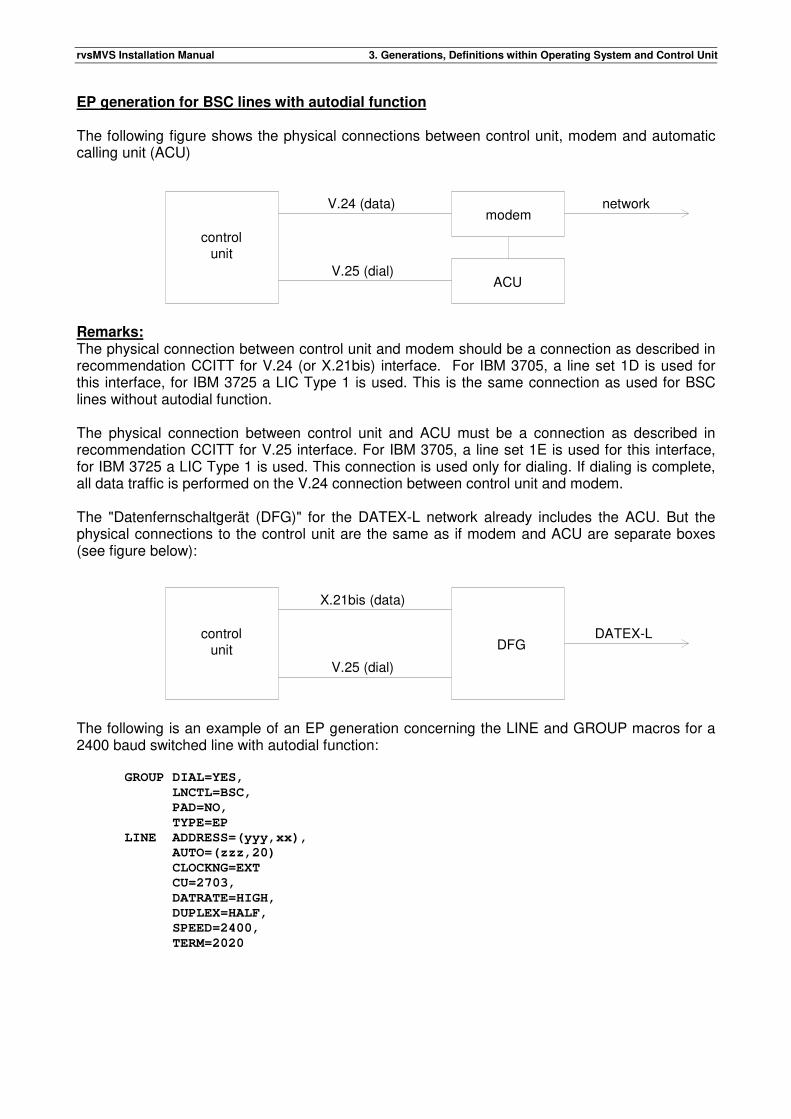
EP generation for BSC lines with autodial function The following figure shows the physical connections between control unit, modem and automatic calling unit (ACU)
Remarks: The physical connection between control unit and modem should be a connection as described in recommendation CCITT for V.24 (or X.21bis) interface. For IBM 3705, a line set 1D is used for this interface, for IBM 3725 a LIC Type 1 is used. This is the same connection as used for BSC lines without autodial function. The physical connection between control unit and ACU must be a connection as described in recommendation CCITT for V.25 interface. For IBM 3705, a line set 1E is used for this interface, for IBM 3725 a LIC Type 1 is used. This connection is used only for dialing. If dialing is complete, all data traffic is performed on the V.24 connection between control unit and modem. The "Datenfernschaltgerät (DFG)" for the DATEX-L network already includes the ACU. But the physical connections to the control unit are the same as if modem and ACU are separate boxes (see figure below):
The following is an example of an EP generation concerning the LINE and GROUP macros for a 2400 baud switched line with autodial function: GROUP DIAL=YES,
LNCTL=BSC,
PAD=NO,
TYPE=EP
LINE ADDRESS=(yyy,xx),
AUTO=(zzz,20)
CLOCKNG=EXT
CU=2703,
DATRATE=HIGH,
DUPLEX=HALF,
SPEED=2400,
TERM=2020
controlunit
modem
ACU
V.24 (data)
V.25 (dial)
network
controlunit
X.21bis (data)
V.25 (dial)
DATEX-LDFG
rvsMVS Installation Manual 3. Generations, Definitions within Operating System and Control Unit
Remarks:
• The parameters "DIAL=YES", "DUPLEX=HALF", "LNCTL=BSC" and "PAD=NO" are mandatory.
• The parameter "CLOCKNG=EXT" should be specified for every line, except for lines with a speed of 1200 baud. If "SPEED=1200" is specified, "CLOCKNG=INT" should be specified instead.
• "xx" denotes the last two characters of the MVS address for this line as specified in the IODEVICE macro, "yyy" denotes the address of the control unit for the V.24 (or X.21bis) interface, "zzz" denotes the address of the control unit for the V.25 interface used for dialing.
• The only difference between generation of a switched line with autodial function and generation of a switched line without autodial function is the coding of the "AUTO" parameter.
3.1.3. BSC lines with autodial function (Interface V.25bis)
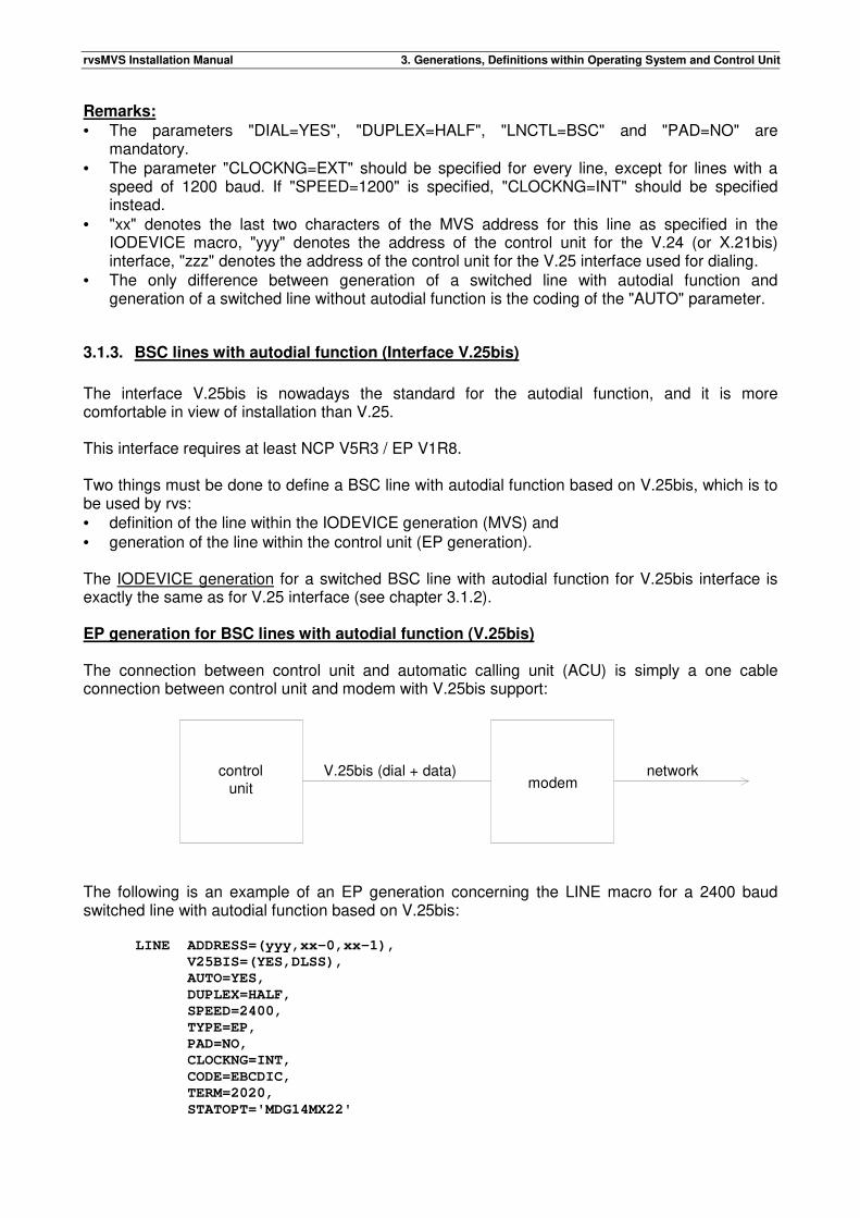
The interface V.25bis is nowadays the standard for the autodial function, and it is more comfortable in view of installation than V.25. This interface requires at least NCP V5R3 / EP V1R8. Two things must be done to define a BSC line with autodial function based on V.25bis, which is to be used by rvs: • definition of the line within the IODEVICE generation (MVS) and • generation of the line within the control unit (EP generation). The IODEVICE generation for a switched BSC line with autodial function for V.25bis interface is exactly the same as for V.25 interface (see chapter 3.1.2). EP generation for BSC lines with autodial function (V.25bis) The connection between control unit and automatic calling unit (ACU) is simply a one cable connection between control unit and modem with V.25bis support:
The following is an example of an EP generation concerning the LINE macro for a 2400 baud switched line with autodial function based on V.25bis: LINE ADDRESS=(yyy,xx-0,xx-1),
V25BIS=(YES,DLSS),
AUTO=YES,
DUPLEX=HALF,
SPEED=2400,
TYPE=EP,
PAD=NO,
CLOCKNG=INT,
CODE=EBCDIC,
TERM=2020,
STATOPT='MDG14MX22'
controlunit
V.25bis (dial + data) networkmodem
rvsMVS Installation Manual 3. Generations, Definitions within Operating System and Control Unit
Remarks: "xx" denotes the last two characters of the MVS address for this line as specified in the IODEVICE macro, "yyy" denotes the address of the control unit for the V.25bis interface.
3.2. Definitions for SNA component of rvs
This section describes VTAM definitions which are necessary for a SNA connection between the local and a remote rvs installation. The following requirements must be satisfied in order to establish a SNA connection with a remote rvs installation: • The local rvs installation must include the SNA component. • The remote rvs installation must include the SNA component (rvsMVS) or the remote side has
installed rvsVSE/SNA. • Local and remote hosts must be connected via SNA network. It is possible to connect PU type 2 computers with rvs using the SNA component. In this case, rvs-compatible software is required for the remote computer, but the restriction to leased line connections must not be necessary. For a list of PU type 2 computers, which are already connected to rvs using the SNA component, see rvsMVS Interface Description. VTAM definitions for the local rvs installation: The local rvs installation must be defined within VTAM as a separate VTAM application: VBUILD TYPE=APPL
rvsA APPL AUTH=(ACQ),
PARSESS=YES,
VPACING=7,
MODETAB=LMTrvs,
DLOGMOD=rvs1
Remark: The name of the APPL statement (here: RVSA) must be the same as specified for the rvs start parameter "APPLID", see chapter 6.1. Log mode table for rvs: It may be useful to define a separate log mode table for RVS. The use of log mode entries with different COS names allow the use of different "Virtual Routes" for different parallel sessions between the local and remote rvs installation (application). A special log mode entry will be used by rvs during activation of a session to the remote application (rvs installation) if • the name of the log mode to be used for this session is specified within the rvs Sessions Table
(see chapter 6.4, description of columns 53-60) • the activation of the session is a result of an activation command in the local rvs installation
(see rvs Operation Manual, activation command "A-sid").
rvsMVS Installation Manual 3. Generations, Definitions within Operating System and Control Unit
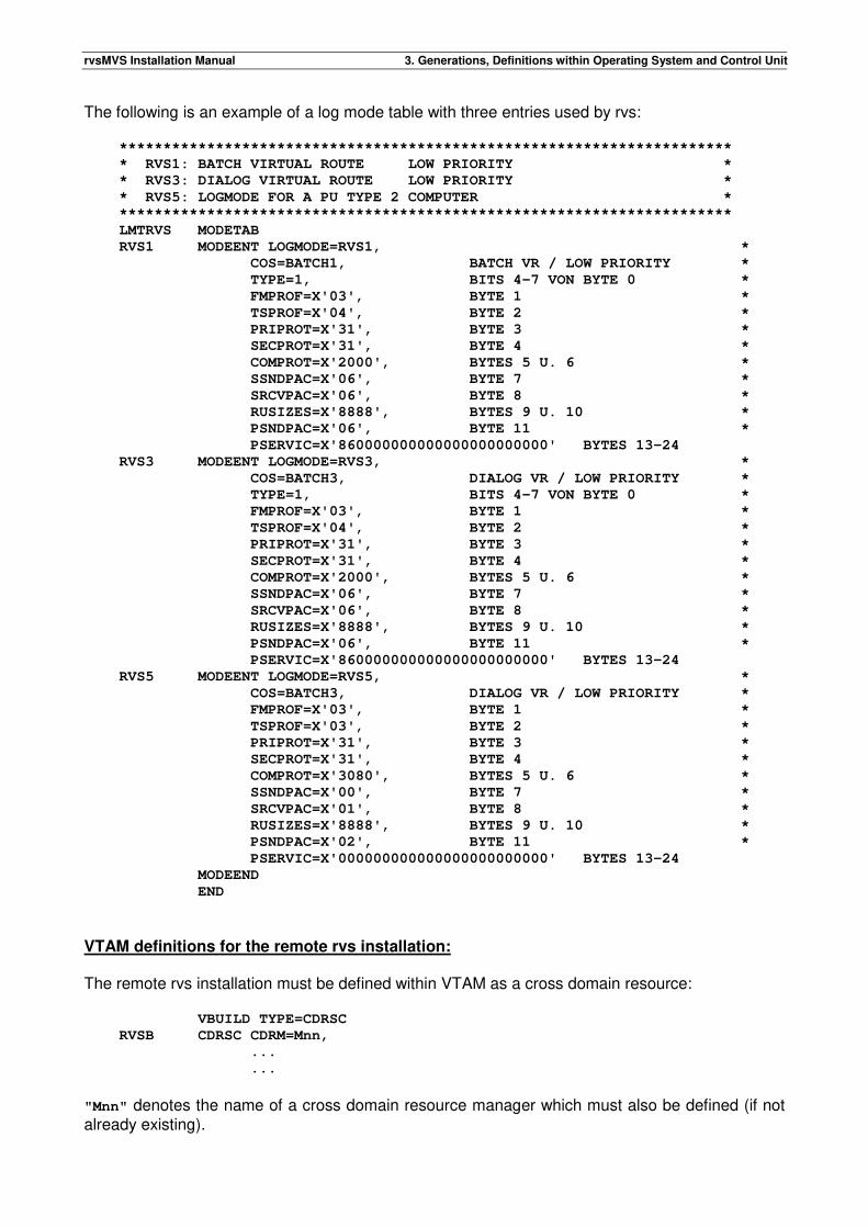
The following is an example of a log mode table with three entries used by rvs: **********************************************************************
* RVS1: BATCH VIRTUAL ROUTE LOW PRIORITY *
* RVS3: DIALOG VIRTUAL ROUTE LOW PRIORITY *
* RVS5: LOGMODE FOR A PU TYPE 2 COMPUTER *
**********************************************************************
LMTRVS MODETAB
RVS1 MODEENT LOGMODE=RVS1, *
COS=BATCH1, BATCH VR / LOW PRIORITY *
TYPE=1, BITS 4-7 VON BYTE 0 *
FMPROF=X'03', BYTE 1 *
TSPROF=X'04', BYTE 2 *
PRIPROT=X'31', BYTE 3 *
SECPROT=X'31', BYTE 4 *
COMPROT=X'2000', BYTES 5 U. 6 *
SSNDPAC=X'06', BYTE 7 *
SRCVPAC=X'06', BYTE 8 *
RUSIZES=X'8888', BYTES 9 U. 10 *
PSNDPAC=X'06', BYTE 11 *
PSERVIC=X'860000000000000000000000' BYTES 13-24
RVS3 MODEENT LOGMODE=RVS3, *
COS=BATCH3, DIALOG VR / LOW PRIORITY *
TYPE=1, BITS 4-7 VON BYTE 0 *
FMPROF=X'03', BYTE 1 *
TSPROF=X'04', BYTE 2 *
PRIPROT=X'31', BYTE 3 *
SECPROT=X'31', BYTE 4 *
COMPROT=X'2000', BYTES 5 U. 6 *
SSNDPAC=X'06', BYTE 7 *
SRCVPAC=X'06', BYTE 8 *
RUSIZES=X'8888', BYTES 9 U. 10 *
PSNDPAC=X'06', BYTE 11 *
PSERVIC=X'860000000000000000000000' BYTES 13-24
RVS5 MODEENT LOGMODE=RVS5, *
COS=BATCH3, DIALOG VR / LOW PRIORITY *
FMPROF=X'03', BYTE 1 *
TSPROF=X'03', BYTE 2 *
PRIPROT=X'31', BYTE 3 *
SECPROT=X'31', BYTE 4 *
COMPROT=X'3080', BYTES 5 U. 6 *
SSNDPAC=X'00', BYTE 7 *
SRCVPAC=X'01', BYTE 8 *
RUSIZES=X'8888', BYTES 9 U. 10 *
PSNDPAC=X'02', BYTE 11 *
PSERVIC=X'000000000000000000000000' BYTES 13-24
MODEEND
END
VTAM definitions for the remote rvs installation: The remote rvs installation must be defined within VTAM as a cross domain resource: VBUILD TYPE=CDRSC
RVSB CDRSC CDRM=Mnn,
...
...
"Mnn" denotes the name of a cross domain resource manager which must also be defined (if not already existing).
rvsMVS Installation Manual 3. Generations, Definitions within Operating System and Control Unit
Example for a definition of a cross domain resource manager: VBUILD TYPE=CDRM
Mxx CDRM SUBAREA=xx,
CDRDYN=YES,
CDRSC=OPT
Mnn CDRM SUBAREA=nn,
CDRDYN=YES,
CDRSC=OPT
...
...
Definition of ACF/VTAM routes to the remote host (example): Fxxnn PATH DESTSA=nn,
ER0=(yy,1),
VR0=0
...
...
Remarks:
• "nn" denotes the sub area of the remote host (remote rvs installation). • "xx" denotes the sub area of the local host. • "yy" denotes the sub area of the next node (host), if the connection between local and remote
host is not a direct connection. • The name of the cross domain resource for the remote rvs (here: rvsB) must be specified
within the rvs Stations Table (entry for the remote rvs installation, see chapter 6.2, parameter "LUNAME").
3.3. Definitions for X25 component of rvs
3.3.1. Definitions for using the X.25 network via XOT
This section describes the principles of X.25 connections via XOT. XOT is a protocol for transmitting X.25 packets over a TCP/IP network. It was recommended by CISCO as RFC1613. An XOT capable hardware is able to extract the X.25 packets from XOT and send it over an X.25 network. The following requirements must be satisfied in order to establish an X.25 connection with a remote station: • The local rvs installation must include the X.25 component. • The local control unit must include the IBM TCP/IP program product. • TCP/IP connection to an XOT capable hardware (e.g. CISCO- or BINTEC- Router) • The remote installation must support the "ODETTE File Transfer Protocol". • Both installations must have an X.25 multi channel link. For further information about router configuration see router manuals.
3.3.2. Definitions for using the X.25 network via NPSI
This section describes VTAM definitions and NPSI definitions which are necessary for a X.25 connection between the local and a remote installation.
rvsMVS Installation Manual 3. Generations, Definitions within Operating System and Control Unit
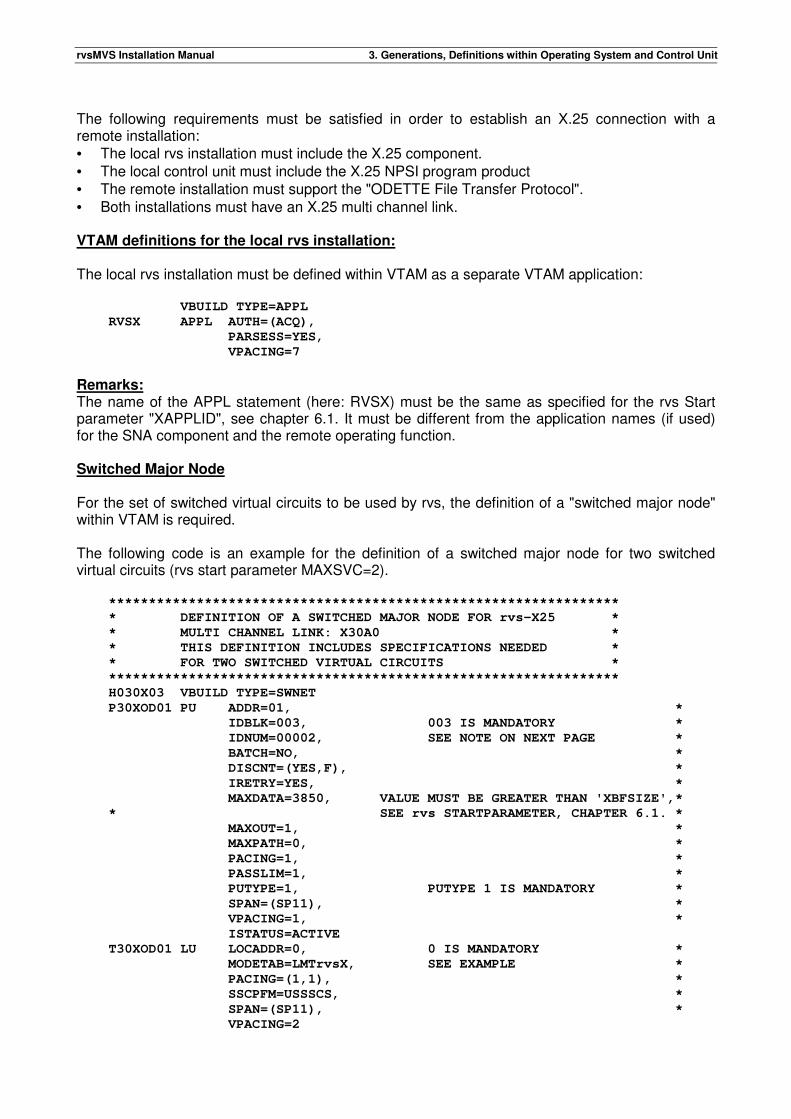
The following requirements must be satisfied in order to establish an X.25 connection with a remote installation: • The local rvs installation must include the X.25 component. • The local control unit must include the X.25 NPSI program product • The remote installation must support the "ODETTE File Transfer Protocol". • Both installations must have an X.25 multi channel link. VTAM definitions for the local rvs installation: The local rvs installation must be defined within VTAM as a separate VTAM application: VBUILD TYPE=APPL
RVSX APPL AUTH=(ACQ),
PARSESS=YES,
VPACING=7
Remarks: The name of the APPL statement (here: RVSX) must be the same as specified for the rvs Start parameter "XAPPLID", see chapter 6.1. It must be different from the application names (if used) for the SNA component and the remote operating function. Switched Major Node For the set of switched virtual circuits to be used by rvs, the definition of a "switched major node" within VTAM is required. The following code is an example for the definition of a switched major node for two switched virtual circuits (rvs start parameter MAXSVC=2). ****************************************************************
* DEFINITION OF A SWITCHED MAJOR NODE FOR rvs-X25 *
* MULTI CHANNEL LINK: X30A0 *
* THIS DEFINITION INCLUDES SPECIFICATIONS NEEDED *
* FOR TWO SWITCHED VIRTUAL CIRCUITS *
****************************************************************
H030X03 VBUILD TYPE=SWNET
P30XOD01 PU ADDR=01, *
IDBLK=003, 003 IS MANDATORY *
IDNUM=00002, SEE NOTE ON NEXT PAGE *
BATCH=NO, *
DISCNT=(YES,F), *
IRETRY=YES, *
MAXDATA=3850, VALUE MUST BE GREATER THAN 'XBFSIZE',*
* SEE rvs STARTPARAMETER, CHAPTER 6.1. *
MAXOUT=1, *
MAXPATH=0, *
PACING=1, *
PASSLIM=1, *
PUTYPE=1, PUTYPE 1 IS MANDATORY *
SPAN=(SP11), *
VPACING=1, *
ISTATUS=ACTIVE
T30XOD01 LU LOCADDR=0, 0 IS MANDATORY *
MODETAB=LMTrvsX, SEE EXAMPLE *
PACING=(1,1), *
SSCPFM=USSSCS, *
SPAN=(SP11), *
VPACING=2
rvsMVS Installation Manual 3. Generations, Definitions within Operating System and Control Unit
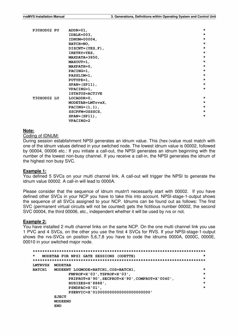
P30XOD02 PU ADDR=01, *
IDBLK=003, *
IDNUM=00004, *
BATCH=NO, *
DISCNT=(YES,F), *
IRETRY=YES, *
MAXDATA=3850, *
MAXOUT=1, *
MAXPATH=0, *
PACING=1, *
PASSLIM=1, *
PUTYPE=1, *
SPAN=(SP11), *
VPACING=1, *
ISTATUS=ACTIVE
T30XOD02 LU LOCADDR=0, *
MODETAB=LMTrvsX, *
PACING=(1,1), *
SSCPFM=USSSCS, *
SPAN=(SP11), *
VPACING=2
Note: Coding of IDNUM: During session establishment NPSI generates an idnum value. This (hex-)value must match with one of the idnum values defined in your switched node. The lowest idnum value is 00002, followed by 00004, 00006 etc.: If you initiate a call-out, the NPSI generates an idnum beginning with the number of the lowest non-busy channel. If you receive a call-in, the NPSI generates the idnum of the highest non busy SVC. Example 1: You defined 5 SVCs on your multi channel link. A call-out will trigger the NPSI to generate the idnum value 00002. A call-in will lead to 0000A. Please consider that the sequence of idnum mustn't necessarily start with 00002. If you have defined other SVCs in your NCP you have to take this into account. NPSI-stage-1-output shows the sequence of all SVCs assigned to your NCP. Idnums can be found out as follows: The first SVC (permanent virtual circuits will not be counted) gets the fictitious number 00002, the second SVC 00004, the third 00006, etc., independent whether it will be used by rvs or not. Example 2: You have installed 2 multi channel links on the same NCP. On the one multi channel link you use 1 PVC and 4 SVCs, on the other you use the first 4 SVCs for RVS. If your NPSI-stage-1-output shows the rvs-SVCs on position 5,6,7,8 you have to code the idnums 0000A, 0000C, 0000E, 00010 in your switched major node. ************************************************************************
* MODETAB FOR NPSI GATE SESSIONS (ODETTE) *
************************************************************************
LMTRVSX MODETAB
BATCH1 MODEENT LOGMODE=BATCH1,COS=BATCH1, *
FMPROF=X'03',TSPROF=X'03', *
PRIPROT=X'90',SECPROT=X'90',COMPROT=X'0040', *
RUSIZES=X'8888', *
PSNDPAC=X'01', *
PSERVIC=X'010000000000000000000000'
EJECT
MODEEND
END
rvsMVS Installation Manual 3. Generations, Definitions within Operating System and Control Unit
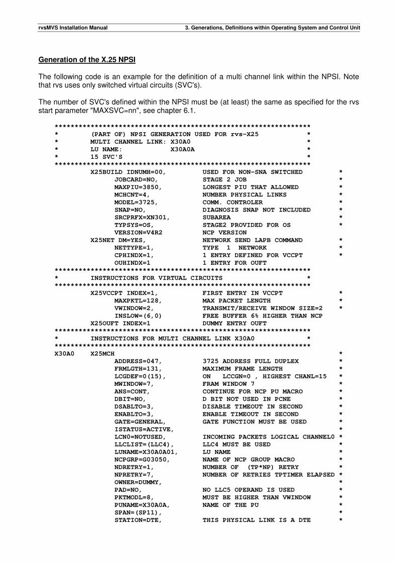
Generation of the X.25 NPSI The following code is an example for the definition of a multi channel link within the NPSI. Note that rvs uses only switched virtual circuits (SVC's). The number of SVC's defined within the NPSI must be (at least) the same as specified for the rvs start parameter "MAXSVC=nn", see chapter 6.1. ****************************************************************
* (PART OF) NPSI GENERATION USED FOR rvs-X25 *
* MULTI CHANNEL LINK: X30A0 *
* LU NAME: X30A0A *
* 15 SVC'S *
****************************************************************
X25BUILD IDNUMH=00, USED FOR NON-SNA SWITCHED *
JOBCARD=NO, STAGE 2 JOB *
MAXPIU=3850, LONGEST PIU THAT ALLOWED *
MCHCNT=4, NUMBER PHYSICAL LINKS *
MODEL=3725, COMM. CONTROLER *
SNAP=NO, DIAGNOSIS SNAP NOT INCLUDED *
SRCPRFX=XN301, SUBAREA *
TYPSYS=OS, STAGE2 PROVIDED FOR OS *
VERSION=V4R2 NCP VERSION
X25NET DM=YES, NETWORK SEND LAPB COMMAND *
NETTYPE=1, TYPE 1 NETWORK *
CPHINDX=1, 1 ENTRY DEFINED FOR VCCPT *
OUHINDX=1 1 ENTRY FOR OUFT
****************************************************************
* INSTRUCTIONS FOR VIRTUAL CIRCUITS *
****************************************************************
X25VCCPT INDEX=1, FIRST ENTRY IN VCCPT *
MAXPKTL=128, MAX PACKET LENGTH *
VWINDOW=2, TRANSMIT/RECEIVE WINDOW SIZE=2 *
INSLOW=(6,0) FREE BUFFER 6% HIGHER THAN NCP
X25OUFT INDEX=1 DUMMY ENTRY OUFT
****************************************************************
* INSTRUCTIONS FOR MULTI CHANNEL LINK X30A0 *
****************************************************************
X30A0 X25MCH *
ADDRESS=047, 3725 ADDRESS FULL DUPLEX *
FRMLGTH=131, MAXIMUM FRAME LENGTH *
LCGDEF=0(15), ON LCCGN=0 , HIGHEST CHANL=15 *
MWINDOW=7, FRAM WINDOW 7 *
ANS=CONT, CONTINUE FOR NCP PU MACRO *
DBIT=NO, D BIT NOT USED IN PCNE *
DSABLTO=3, DISABLE TIMEOUT IN SECOND *
ENABLTO=3, ENABLE TIMEOUT IN SECOND *
GATE=GENERAL, GATE FUNCTION MUST BE USED *
ISTATUS=ACTIVE, *
LCN0=NOTUSED, INCOMING PACKETS LOGICAL CHANNEL0 *
LLCLIST=(LLC4), LLC4 MUST BE USED *
LUNAME=X30A0A01, LU NAME *
NCPGRP=G03050, NAME OF NCP GROUP MACRO *
NDRETRY=1, NUMBER OF (TP*NP) RETRY *
NPRETRY=7, NUMBER OF RETRIES TPTIMER ELAPSED *
OWNER=DUMMY, *
PAD=NO, NO LLC5 OPERAND IS USED *
PKTMODL=8, MUST BE HIGHER THAN VWINDOW *
PUNAME=X30A0A, NAME OF THE PU *
SPAN=(SP11), *
STATION=DTE, THIS PHYSICAL LINK IS A DTE *
rvsMVS Installation Manual 3. Generations, Definitions within Operating System and Control Unit
TDTIMER=1, TIMER TO WAIT FOR ND RETRIES *
TRAN=NO, NO TRANSLATION IS TO BE PERFORMED *
TPTIMER=1 X.25 T1 TIMER IN SECONDS
X25LCG LCGN=0 LOGICAL CHANNEL GROUP=0
****************************************************************
* INSTRUCTIONS FOR 15 SWITCHED VIRTUAL CIRCUITS *
****************************************************************
X25VC *
SPAN=(SP11), *
LCN=(1,15), 15 VIRTUELLE LINES *
TYPE=SWITCHED, *
OUFINDX=1, DEFIND IN X25OUFT MACRO *
VCCINDX=1, VIRTUAL CICUIT *
CALL=INOUT, *
COMMITO=4, COMMIT TIMEOUT *
ISTATUS=ACTIVE, *
MAXLU=3, NUMBER OF LU'S FROM PU IN VTAM *
NCPGRP=G03051, NCP GROUP NAME *
OWNER=DUMMY, *
RETVCTO=30, TIMER BETWEEN RETRANSMISSIONS *
RETVCCT=5 NUMBER OF RETRANSMISSIONS
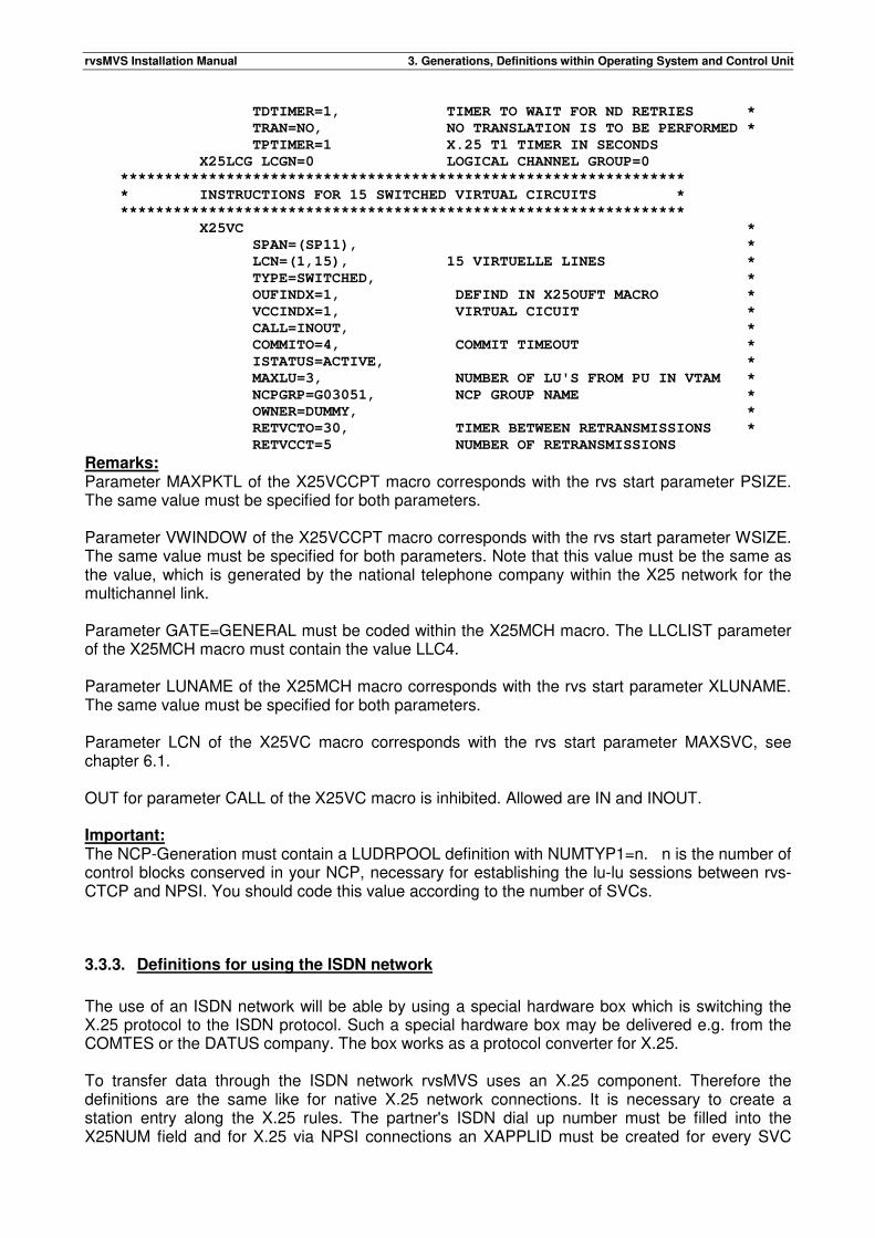
Remarks: Parameter MAXPKTL of the X25VCCPT macro corresponds with the rvs start parameter PSIZE. The same value must be specified for both parameters. Parameter VWINDOW of the X25VCCPT macro corresponds with the rvs start parameter WSIZE. The same value must be specified for both parameters. Note that this value must be the same as the value, which is generated by the national telephone company within the X25 network for the multichannel link. Parameter GATE=GENERAL must be coded within the X25MCH macro. The LLCLIST parameter of the X25MCH macro must contain the value LLC4. Parameter LUNAME of the X25MCH macro corresponds with the rvs start parameter XLUNAME. The same value must be specified for both parameters. Parameter LCN of the X25VC macro corresponds with the rvs start parameter MAXSVC, see chapter 6.1. OUT for parameter CALL of the X25VC macro is inhibited. Allowed are IN and INOUT. Important: The NCP-Generation must contain a LUDRPOOL definition with NUMTYP1=n. n is the number of control blocks conserved in your NCP, necessary for establishing the lu-lu sessions between rvs-CTCP and NPSI. You should code this value according to the number of SVCs.
3.3.3. Definitions for using the ISDN network
The use of an ISDN network will be able by using a special hardware box which is switching the X.25 protocol to the ISDN protocol. Such a special hardware box may be delivered e.g. from the COMTES or the DATUS company. The box works as a protocol converter for X.25. To transfer data through the ISDN network rvsMVS uses an X.25 component. Therefore the definitions are the same like for native X.25 network connections. It is necessary to create a station entry along the X.25 rules. The partner's ISDN dial up number must be filled into the X25NUM field and for X.25 via NPSI connections an XAPPLID must be created for every SVC
rvsMVS Installation Manual 3. Generations, Definitions within Operating System and Control Unit
which is connected to the hardware box. Chapters 6.1.1 and 6.2.10 show examples for mixed definitions of X.25 and ISDN network.
rvsMVS Installation Manual 3. Generations, Definitions within Operating System and Control Unit
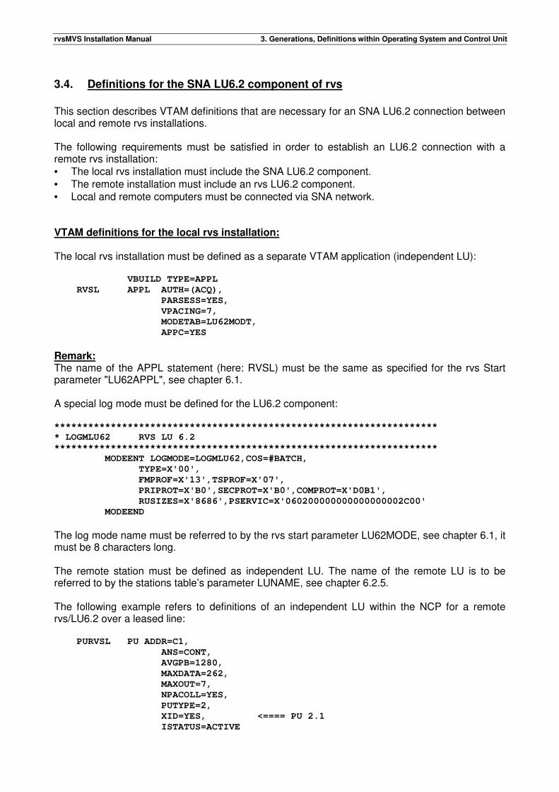
3.4. Definitions for the SNA LU6.2 component of rvs
This section describes VTAM definitions that are necessary for an SNA LU6.2 connection between local and remote rvs installations. The following requirements must be satisfied in order to establish an LU6.2 connection with a remote rvs installation: • The local rvs installation must include the SNA LU6.2 component. • The remote installation must include an rvs LU6.2 component. • Local and remote computers must be connected via SNA network. VTAM definitions for the local rvs installation: The local rvs installation must be defined as a separate VTAM application (independent LU): VBUILD TYPE=APPL
RVSL APPL AUTH=(ACQ),
PARSESS=YES,
VPACING=7,
MODETAB=LU62MODT,
APPC=YES
Remark: The name of the APPL statement (here: RVSL) must be the same as specified for the rvs Start parameter "LU62APPL", see chapter 6.1. A special log mode must be defined for the LU6.2 component: ********************************************************************
* LOGMLU62 RVS LU 6.2
********************************************************************
MODEENT LOGMODE=LOGMLU62,COS=#BATCH,
TYPE=X'00',
FMPROF=X'13',TSPROF=X'07',
PRIPROT=X'B0',SECPROT=X'B0',COMPROT=X'D0B1',
RUSIZES=X'8686',PSERVIC=X'060200000000000000002C00'
MODEEND
The log mode name must be referred to by the rvs start parameter LU62MODE, see chapter 6.1, it must be 8 characters long. The remote station must be defined as independent LU. The name of the remote LU is to be referred to by the stations table’s parameter LUNAME, see chapter 6.2.5. The following example refers to definitions of an independent LU within the NCP for a remote rvs/LU6.2 over a leased line: PURVSL PU ADDR=C1,
ANS=CONT,
AVGPB=1280,
MAXDATA=262,
MAXOUT=7,
NPACOLL=YES,
PUTYPE=2,
XID=YES, <==== PU 2.1
ISTATUS=ACTIVE
rvsMVS Installation Manual 3. Generations, Definitions within Operating System and Control Unit
*****************************
LURVSL LU LOCADDR=0,
DLOGMOD=LOGMLU62,
MODETAB=LU62MODT,
PACING=7,
RESSCB=5,
SSCPFM=FSS,
VPACING=7,
ISTATUS=ACTIVE
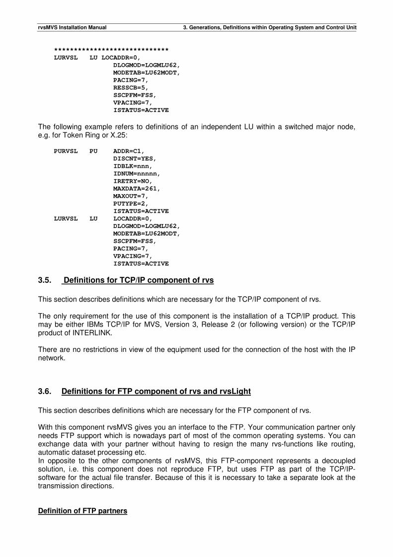
The following example refers to definitions of an independent LU within a switched major node, e.g. for Token Ring or X.25: PURVSL PU ADDR=C1,
DISCNT=YES,
IDBLK=nnn,
IDNUM=nnnnn,
IRETRY=NO,
MAXDATA=261,
MAXOUT=7,
PUTYPE=2,
ISTATUS=ACTIVE
LURVSL LU LOCADDR=0,
DLOGMOD=LOGMLU62,
MODETAB=LU62MODT,
SSCPFM=FSS,
PACING=7,
VPACING=7,
ISTATUS=ACTIVE
3.5. Definitions for TCP/IP component of rvs
This section describes definitions which are necessary for the TCP/IP component of rvs. The only requirement for the use of this component is the installation of a TCP/IP product. This may be either IBMs TCP/IP for MVS, Version 3, Release 2 (or following version) or the TCP/IP product of INTERLINK. There are no restrictions in view of the equipment used for the connection of the host with the IP network.
3.6. Definitions for FTP component of rvs and rvsLight
This section describes definitions which are necessary for the FTP component of rvs. With this component rvsMVS gives you an interface to the FTP. Your communication partner only needs FTP support which is nowadays part of most of the common operating systems. You can exchange data with your partner without having to resign the many rvs-functions like routing, automatic dataset processing etc. In opposite to the other components of rvsMVS, this FTP-component represents a decoupled solution, i.e. this component does not reproduce FTP, but uses FTP as part of the TCP/IP-software for the actual file transfer. Because of this it is necessary to take a separate look at the transmission directions. Definition of FTP partners
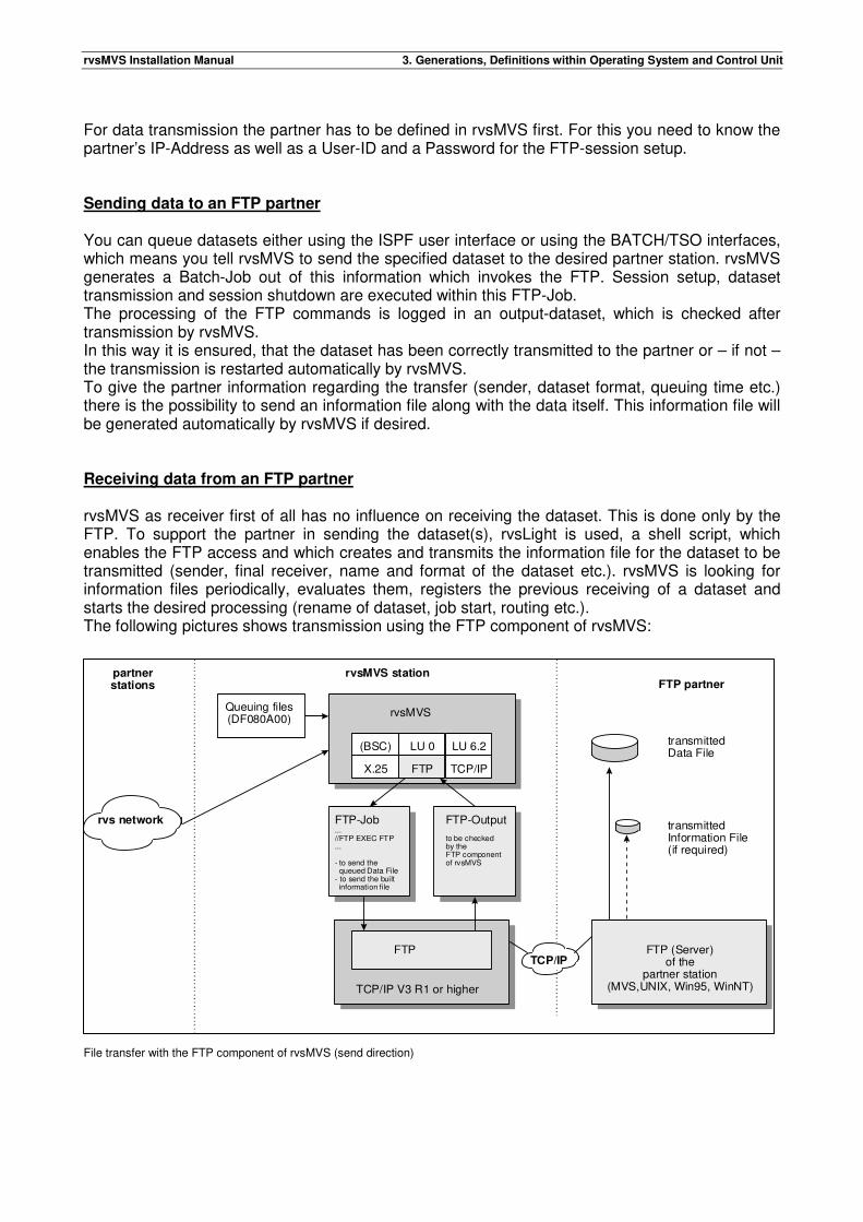
rvsMVS Installation Manual 3. Generations, Definitions within Operating System and Control Unit
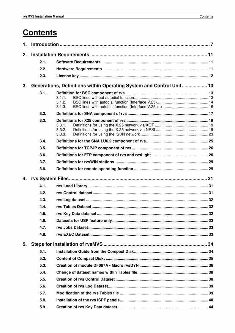
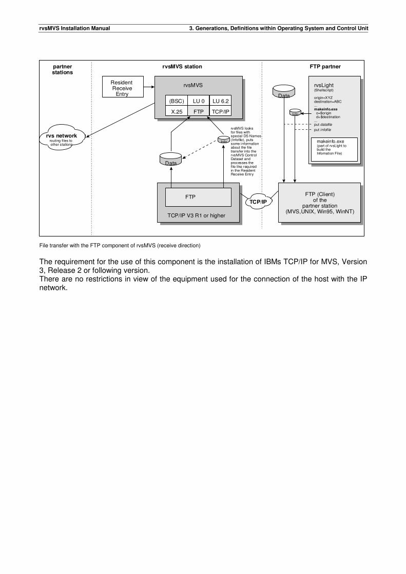
For data transmission the partner has to be defined in rvsMVS first. For this you need to know the partner’s IP-Address as well as a User-ID and a Password for the FTP-session setup. Sending data to an FTP partner You can queue datasets either using the ISPF user interface or using the BATCH/TSO interfaces, which means you tell rvsMVS to send the specified dataset to the desired partner station. rvsMVS generates a Batch-Job out of this information which invokes the FTP. Session setup, dataset transmission and session shutdown are executed within this FTP-Job. The processing of the FTP commands is logged in an output-dataset, which is checked after transmission by rvsMVS. In this way it is ensured, that the dataset has been correctly transmitted to the partner or – if not – the transmission is restarted automatically by rvsMVS. To give the partner information regarding the transfer (sender, dataset format, queuing time etc.) there is the possibility to send an information file along with the data itself. This information file will be generated automatically by rvsMVS if desired. Receiving data from an FTP partner rvsMVS as receiver first of all has no influence on receiving the dataset. This is done only by the FTP. To support the partner in sending the dataset(s), rvsLight is used, a shell script, which enables the FTP access and which creates and transmits the information file for the dataset to be transmitted (sender, final receiver, name and format of the dataset etc.). rvsMVS is looking for information files periodically, evaluates them, registers the previous receiving of a dataset and starts the desired processing (rename of dataset, job start, routing etc.). The following pictures shows transmission using the FTP component of rvsMVS:
File transfer with the FTP component of rvsMVS (send direction)
rvs network
rvsMVS
(BSC) LU 0 LU 6.2
X.25 FTP TCP/IP
FTP-Job...//FTP EXEC FTP...
- to send the queued Data File- to send the built information file
TCP/IP V3 R1 or higher
FTP
FTP-Output
to be checkedby theFTP componentof rvsMVS
Queuing files(DF080A00)
transmittedData File
transmittedInformation File(if required)
partnerstations
rvsMVS stationFTP partner
FTP (Server)of the
partner station(MVS,UNIX, Win95, WinNT)
TCP/IP
rvsMVS Installation Manual 3. Generations, Definitions within Operating System and Control Unit
File transfer with the FTP component of rvsMVS (receive direction)
The requirement for the use of this component is the installation of IBMs TCP/IP for MVS, Version 3, Release 2 or following version. There are no restrictions in view of the equipment used for the connection of the host with the IP network.
rvs networkrouting files to other stations
rvsMVS
(BSC) LU 0 LU 6.2
X.25 FTP TCP/IP
TCP/IP V3 R1 or higher
FTP
Resident Receive
Entry
partnerstations
rvsMVS station FTP partner
FTP (Client)of the
partner station(MVS,UNIX, Win95, WinNT)
rvsLight(Shellscript)
origin=XYZdestination=ABC...makeinfo.exe o=$origin d=$destination...put datafile
put infofile
makeinfo.exe(part of rvsLight tobuild the Infomation File)
Data
Info
Data
Info
rvsMVS looksfor files withspecial DS Names(Infofile), putssome informationabout the filetransfer into thervsMVS ControlDataset andprocesses thefile like requiredin the ResidentReceive Entry
TCP/IP
rvsMVS Installation Manual 3. Generations, Definitions within Operating System and Control Unit
3.7. Definitions for rvsWIN stations
This section contents special hints for using rvsWIN. Creating rvsWIN installation disks The rvsMVS installation tape contains the file 'RVS.RVSWIN.EXE'. After copying this file to disk on MVS host, you have to transfer this file to your PC. You should use the file transfer function of the 3270 terminal emulation on your PC (options: without including CR LF, without code translation). This dataset is a self-extracting file and it will create the directory /RVSSETUP on your PC. This directory contains all rvsWIN installation files. Defining rvsWIN stations You can find the definitions for rvsWIN stations in chapter 6.2.2 and 6.2.10 of this manual. Running rvsWIN To run rvsWIN, the rvsWIN user needs following information and authorization: rvsWIN Stations-ID (defined in rvsMVS Stations Table, see chapter 6.2.2) fixed password or RACF authorization Application ID (LU name) of rvsMVS SNA component (defined in member "CNTL" of rvsMVS table file; parameter "APPLID=...") In addition the rvsWIN user needs authorization to enter the following LOGON line (including DATA operator) from his terminal (PC with 3270 emulator). rvsWIN creates this LOGON for session establishment: LOGON APPLID(applid) DATA(WI/sid)
applid: application identification of rvsMVS SNA component
sid: rvsWIN Station-ID
It is possible that you have to change some VTAM definitions.
3.8. Definitions for remote operating function
This section describes VTAM definitions which are necessary if the remote operating function shall be used. The only requirement for the use of the remote operating function is the definition of an application within VTAM: VBUILD TYPE=APPL
RVSO APPL AUTH=(ACQ),
PARSESS=NO,
Remark: The name of the APPL statement (here: rvsO) must be the same as specified for the rvs Start parameter "RMOPAPPL", see chapter 6.1.

rvsMVS Installation Manual 3. Generations, Definitions within Operating System and Control Unit
This page will be intentionally empty.
rvsMVS Installation Manual 4. rvs System Files
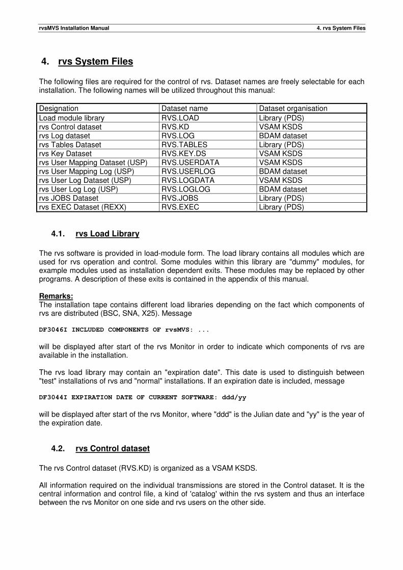
4. rvs System Files The following files are required for the control of rvs. Dataset names are freely selectable for each installation. The following names will be utilized throughout this manual:
Designation Dataset name Dataset organisation
Load module library RVS.LOAD Library (PDS) rvs Control dataset RVS.KD VSAM KSDS rvs Log dataset RVS.LOG BDAM dataset rvs Tables Dataset RVS.TABLES Library (PDS) rvs Key Dataset RVS.KEY.DS VSAM KSDS rvs User Mapping Dataset (USP) RVS.USERDATA VSAM KSDS rvs User Mapping Log (USP) RVS.USERLOG BDAM dataset rvs User Log Dataset (USP) RVS.LOGDATA VSAM KSDS rvs User Log Log (USP) RVS.LOGLOG BDAM dataset rvs JOBS Dataset RVS.JOBS Library (PDS) rvs EXEC Dataset (REXX) RVS.EXEC Library (PDS)
4.1. rvs Load Library
The rvs software is provided in load-module form. The load library contains all modules which are used for rvs operation and control. Some modules within this library are "dummy" modules, for example modules used as installation dependent exits. These modules may be replaced by other programs. A description of these exits is contained in the appendix of this manual. Remarks: The installation tape contains different load libraries depending on the fact which components of rvs are distributed (BSC, SNA, X25). Message DF3046I INCLUDED COMPONENTS OF rvsMVS: ...
will be displayed after start of the rvs Monitor in order to indicate which components of rvs are available in the installation. The rvs load library may contain an "expiration date". This date is used to distinguish between "test" installations of rvs and "normal" installations. If an expiration date is included, message DF3044I EXPIRATION DATE OF CURRENT SOFTWARE: ddd/yy
will be displayed after start of the rvs Monitor, where "ddd" is the Julian date and "yy" is the year of the expiration date.
4.2. rvs Control dataset
The rvs Control dataset (RVS.KD) is organized as a VSAM KSDS. All information required on the individual transmissions are stored in the Control dataset. It is the central information and control file, a kind of 'catalog' within the rvs system and thus an interface between the rvs Monitor on one side and rvs users on the other side.
rvsMVS Installation Manual 4. rvs System Files
All requests for transmissions of files are stored in this dataset, and if active, the rvs Monitor scans this file for transmission requests and transmits these files as soon as a transmission path is available. So it is possible to obtain for example status information about all transmissions which • have not yet started (queued send requests) • are just active (in this case record counters for a later restart are saved in the file) • are complete (so it is always possible to display information about transmissions of the last
days) The control dataset contains additional information about the various processing options that shall be executed after a file has been received (for example automatic job start). Remark: The rvs control dataset should be reorganized from time to time depending on the number of CI and CA splits, which have occurred during normal operation of rvs. Too many splits reduce performance when the control dataset is scanned for display of information. For this, reorganization should be done if more than 5 - 8 CA splits have been done. A reorganization should be done by execution of procedure PDF0015A (for SMS use PDF0015B), see chapter 6.9.4 within this manual.
4.3. rvs Log dataset
The rvs log dataset (RVS.LOG) is a formatted sequential dataset (BDAM). All updates of the Control dataset will be logged within this file. The only reason for introduction of this file is the following: The content of the Control dataset changes with every transmission, thus the requirements for a restore of this file in case of a catalog failure or disk error are different from those for other datasets. The Log dataset allows reconstructing a damaged Control dataset without loss of any information at any time. A more detailed description may be found in chapter 6.9.4, section "Saving and Recovery of the rvs Control dataset".
4.4. rvs Tables Dataset
The Tables Dataset (RVS.TABLES) is organized as a PDS. Its members contain different information: • control information and tables which is used for operation of rvs • JCL and procedures which are used for maintenance and operation of rvs • other (optional) information (for example CLISTS) which may be used for rvs Statistics, see
Appendix D. Look for further information chapter 0, 6.10 and 6.11 too.
4.5. rvs Key Data data set
The rvsMVS Key data dataset (RVS.KEY.DS) is organized as a VSAM KSDS.
rvsMVS Installation Manual 4. rvs System Files
It is a necessary data set if the rvs installation want to use the Security Feature. All private and public keys you want to use in an rvs installation have to be stored in the Key Data dataset. This data set is the central information data base for the security feature. It works as an interface between the rvs Monitor and rvs Security Administrator which maintains the security key data. Security keys will be obtained by a data set key of KEYTYPE, SID and KEYID. KEYTYPE may be PU for public keys or PR for private keys, SID is identically with the rvs parameter SID and KEYID is a hexadecimal character string which make the key unique in an rvs installation. The key identification KEYID will be generated by the key generation program and is equal for a key pair consisting of a public and private key. Remark:
• The program DF054K may be used for maintaining the Key Data set. For more information about this program, see appendix I within this manual.
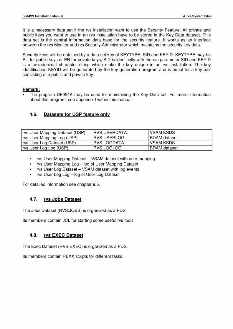
4.6. Datasets for USP feature only
rvs User Mapping Dataset (USP) RVS.USERDATA VSAM KSDS rvs User Mapping Log (USP) RVS.USERLOG BDAM dataset rvs User Log Dataset (USP) RVS.LOGDATA VSAM KSDS rvs User Log Log (USP) RVS.LOGLOG BDAM dataset
• rvs User Mapping Dataset – VSAM dataset with user mapping • rvs User Mapping Log – log of User Mapping Dataset • rvs User Log Dataset – VSAM dataset with log events • rvs User Log Log – log of User Log Dataset
For detailed information see chapter 9.5.
4.7. rvs Jobs Dataset
The Jobs Dataset (RVS.JOBS) is organized as a PDS. Its members contain JCL for starting some useful rvs tools.
4.8. rvs EXEC Dataset
The Exec Dataset (RVS.EXEC) is organized as a PDS. Its members contain REXX scripts for different tasks.
rvsMVS Installation Manual 5. Steps for installation of rvsMVS
5. Steps for installation of rvsMVS The Distribution medium of rvsMVS is Distribution CD.
5.1. Installation Guide from the Compact Disk
The following steps must be performed when installing rvs: 1. System I/O Device generation for all used BSC lines, see chapter 3. 2. Generation of all used BSC lines within the control unit (for example IBM 37x5), see chapter 3. 3. Definition of VTAM resources (if SNA- or X25-component or the remote operating function are
used) and generation of the NPSI if the X25 component is to be used, see chapter 3. 4. Transferring files to the MVS host:
All of the files - except README.TXT (DOC), RVSWIN.EXE, and release info and rvsMVS documentation - are datasets for the MVS environment. These datasets have to be transferred from the workstation to the MVS host. This may be done by various programs using different protocols, e.g. rvsWIN, rvsNT, FTP or 3270-emulations like Extra, Reflection, PC3270 or Irma using the host program IND$FILE. In all cases it is important to use binary mode with recfm=FB and lrecl=80. This is very important in order to be able to reload the datasets correctly on the MVS host. Using rvsWIN you have to choose the option for advanced users - Menu "Options (Einstellungen)","User Level (Benutzerebene)", "Professional (Fortgeschrittene) at first". In order to queue the datasets, it is important to specify fixed record format with record length 80, but NO Text! Be sure to specify a valid first level qualifier for the MVS environment, e.g. your USERID. It may take some time to transfer all files by rvsWIN! For IND$FILE it might be necessary to allocate enough space for the datasets (e.g. 5 cylinders for the load libraries). This may be done in the emulation software when transferring the files. For FTP the options may differ, dependent on the FTP server on the host. Anyhow, record length of 80 and record format FB is mandatory!
5. Reloading the host datasets:
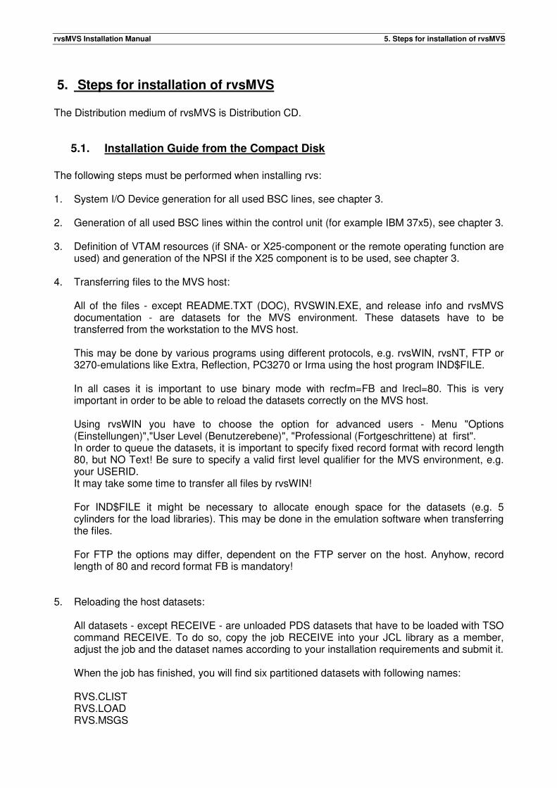
All datasets - except RECEIVE - are unloaded PDS datasets that have to be loaded with TSO command RECEIVE. To do so, copy the job RECEIVE into your JCL library as a member, adjust the job and the dataset names according to your installation requirements and submit it. When the job has finished, you will find six partitioned datasets with following names: RVS.CLIST RVS.LOAD RVS.MSGS
rvsMVS Installation Manual 5. Steps for installation of rvsMVS
RVS.PANEL RVS.SOURCE RVS.TABLES RVS.JOBS RVS.EXEC with first level qualifier "RVS" changed according to your installation requirements. The next steps of installation are described in chapter 5.5 of this manual. Note: After submit of job RECEIVE the message
„FCO760W ALIAS DATUM2 IN INPUT DATASET HAS NO OWNER“ can occur. This message can be ignored.
6. Authorization:
There are two reasons to define the rvs load library as an APF authorized library: • Some status displays for transmissions using the FTP component may be incomplete. • rvs User Exits (see Appendix) have been installed and at least one of these exits requires authorization. If none of the installed User Exit requires APF authorization, it is not necessary to define the rvs load library as an APF authorized library. Independent of the definition of the rvs load library (APF or not), all rvs modules are linked with attribute "AC=1".
7. Creation of module "DF067A", described in chapter 5.3. 8. Creation and Initialization of the rvs Control Dataset, see chapter 5.5. 9. Creation of the rvs Log Dataset, see chapter 5.6. 10. Modification of the rvs Tables Dataset, see chapter 5.7. 11. Installation of rvs ISPF panels, see chapter 5.8 12. Creation and Initialization of the rvs Key Data data set if Security Feature will be used,
see chapter appendix I. If you want to use OFTP2 File services (e.g. Encryption) please also read the corresponding Addendum.
13. Inserting the Security Key of your own and of your partner(s), see chapter appendix I.
14. (optional) Inserting the User und Permission entries in Permission data set members, (see
chapter 9.5). 15. Running test procedures, see chapter 7.
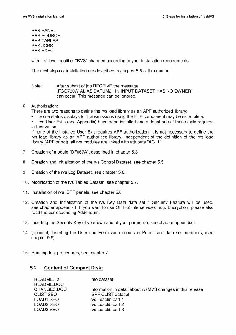
5.2. Content of Compact Disk:
README.TXT Info dataset README.DOC CHANGES.DOC Information in detail about rvsMVS changes in this release CLIST.SEQ ISPF CLIST dataset LOAD1.SEQ rvs Loadlib part 1 LOAD2.SEQ rvs Loadlib part 2 LOAD3.SEQ rvs Loadlib part 3
rvsMVS Installation Manual 5. Steps for installation of rvsMVS
LOAD4.SEQ rvs Loadlib part 4 LOAD5.SEQ rvs Loadlib part 5 LOAD6.SEQ rvs Loadlib part 6 MSGS.SEQ ISPF MSGS dataset PANEL.SEQ ISPF PANEL dataset SOURCE.SEQ Source library. This file contains various source members:
� · layout of rvs control blocks which may be used if rvs User Exits are to be used
� · assembler source code as example of rvs User Exits or other
� installation dependent programs � · sample jobs, useful during installation of RVS. � · macro "rvsDYN", used during installation of rvs
TABLES.SEQ Dataset containing control information for the rvs monitor and jobs used for installation (or operation) of rvs
JOBS.SEQ JOBS dataset EXEC.SEQ EXEC dataset RECEIVE JCL for loading rvsMVS installation datasets
rvsMVS documentation files in Word format
� Installation_Manual.doc � Messages_and_Codes.doc � User_Manual.doc � Benutzer_Handbuch.doc � Operation_Manual.doc � Operator_Handbuch.doc
rvsMVS documentation files in Acrobat Reader format
� Installation_Manual.pdf � Messages_and_Codes.pdf � User_Manual.pdf � Benutzer_Handbuch.pdf � Operation_Manual.pdf � Operator_Handbuch.pdf
5.3. Creation of module DF067A - Macro rvsDYN
rvsMVS requires the generation of a module with name "DF067A". This module contains the (installation dependent) dataset names (and - if used - passwords) of the rvs System files. The dataset names (and - if present - passwords) will be scrambled and stored within the module. This module is used by many rvs programs in order to perform dynamic allocation of one or more of the rvs System files if required. Member "rvsDYN" of the Source Library (second file of the rvs installation tape) contains the macro "rvsDYN", which may be used to create the module. This macro generates JCL statements. Execution of these statements results in assembly and link of module DF067A Caution: For operating system MVS/XA, both, addressing mode (AMODE) and residency mode (RMODE) must be set to 24-bit-addressing.
rvsMVS Installation Manual 5. Steps for installation of rvsMVS
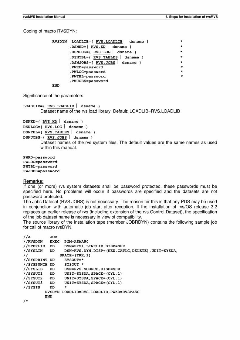
Coding of macro RVSDYN: RVSDYN LOADLIB={ RVS.LOADLIB dsname } *
,DSNKD={ RVS.KD dsname } *
,DSNLOG={ RVS.LOG dsname } *
,DSNTBL={ RVS.TABLES dsname } *
,DSNJOBS={ RVS.JOBS dsname } * ,PWKD=password *
,PWLOG=password *
,PWTBL=password *
,PWJOBS=password
END
Significance of the parameters: LOADLIB={ RVS.LOADLIB dsname }
Dataset name of the rvs load library. Default: LOADLIB=RVS.LOADLIB DSNKD={ RVS.KD dsname }
DSNLOG={ RVS.LOG dsname }
DSNTBL={ RVS.TABLES dsname }
DSNJOBS={ RVS.JOBS dsname }
Dataset names of the rvs system files. The default values are the same names as used within this manual.
PWKD=password
PWLOG=password
PWTBL=password
PWJOBS=password
Remarks: If one (or more) rvs system datasets shall be password protected, these passwords must be specified here. No problems will occur if passwords are specified and the datasets are not password protected. The Jobs Dataset (RVS.JOBS) is not necessary. The reason for this is that any PDS may be used in conjunction with automatic job start after reception. If the installation of rvs/OS release 3.2 replaces an earlier release of rvs (including extension of the rvs Control Dataset), the specification of the job dataset name is necessary in view of compatibility. The source library of the installation tape (member JOBRDYN) contains the following sample job for call of macro rvsDYN. //A JOB
//RVSDYN EXEC PGM=ASMA90
//STEPLIB DD DSN=SYS1.LINKLIB,DISP=SHR
//SYSLIN DD DSN=RVS.DYN,DISP=(NEW,CATLG,DELETE),UNIT=SYSDA,
// SPACE=(TRK,1)
//SYSPRINT DD SYSOUT=*
//SYSPUNCH DD SYSOUT=*
//SYSLIB DD DSN=RVS.SOURCE,DISP=SHR
//SYSUT1 DD UNIT=SYSDA,SPACE=(CYL,1)
//SYSUT2 DD UNIT=SYSDA,SPACE=(CYL,1)
//SYSUT3 DD UNIT=SYSDA,SPACE=(CYL,1)
//SYSIN DD *
RVSDYN LOADLIB=RVS.LOADLIB,PWKD=RVSPASS
END
/*
rvsMVS Installation Manual 5. Steps for installation of rvsMVS
Execution of this job results in creation of JCL, stored in the dataset "RVS.DYN". This JCL should be modified (job card etc.) and executed. For operating system MVS/XA, both, addressing mode (AMODE) and residency mode (RMODE) must be set to 24-bit-addressing.
5.4. Change of dataset names within Tables file
In order to adjust the sample jobs (procedures) of the Tables file to requirements of the installation, the names of the following datasets (unless the names of this manual shall be used) should be changed wherever these names appear in the tables file. • rvs load library (RVS.LOAD) • rvs control dataset (RVS.KD) • rvs log dataset (RVS.LOG) • rvs tables dataset (RVS.TABLES) • rvs key dataset (RVS.KEY.DS)
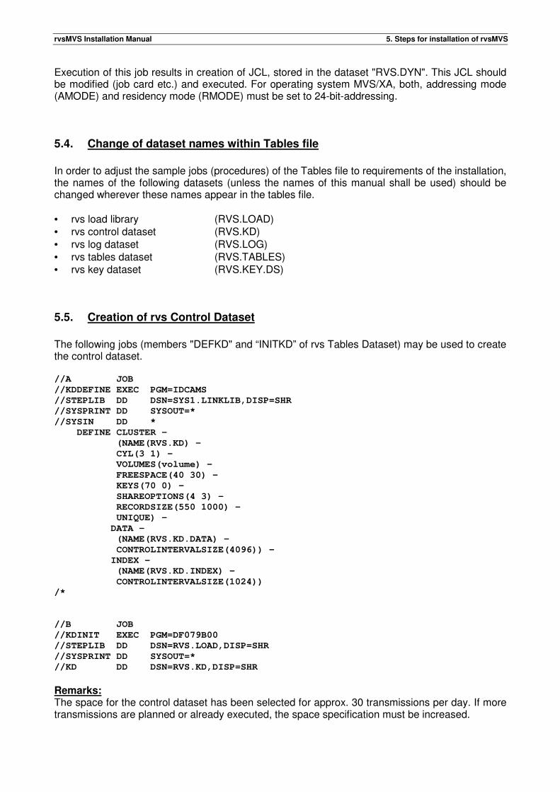
5.5. Creation of rvs Control Dataset
The following jobs (members "DEFKD" and “INITKD” of rvs Tables Dataset) may be used to create the control dataset. //A JOB
//KDDEFINE EXEC PGM=IDCAMS
//STEPLIB DD DSN=SYS1.LINKLIB,DISP=SHR
//SYSPRINT DD SYSOUT=*
//SYSIN DD *
DEFINE CLUSTER -
(NAME(RVS.KD) -
CYL(3 1) -
VOLUMES(volume) -
FREESPACE(40 30) -
KEYS(70 0) -
SHAREOPTIONS(4 3) -
RECORDSIZE(550 1000) -
UNIQUE) -
DATA -
(NAME(RVS.KD.DATA) -
CONTROLINTERVALSIZE(4096)) -
INDEX -
(NAME(RVS.KD.INDEX) -
CONTROLINTERVALSIZE(1024))
/*
//B JOB
//KDINIT EXEC PGM=DF079B00
//STEPLIB DD DSN=RVS.LOAD,DISP=SHR
//SYSPRINT DD SYSOUT=*
//KD DD DSN=RVS.KD,DISP=SHR
Remarks: The space for the control dataset has been selected for approx. 30 transmissions per day. If more transmissions are planned or already executed, the space specification must be increased.
rvsMVS Installation Manual 5. Steps for installation of rvsMVS
The IDCAMS parameter "KEYS", "SHAREOPTIONS" and "RECORDSIZE" should not be modified. If the specified volume is shared between two or more systems, the control dataset should be created on the same volume where the user catalog (containing the catalog entry for the control dataset) resides. If you use SMS, please use the job “DEFKDSMS” to create the control dataset. Warning:
• If catalog and control dataset reside on different volumes in a shared environment, interlock situations and system hang ups may occur.
• If you use KD dataset in SYSPLEX environment, you can get a problem with duplicate indexes. The Problem can occur if a new EXTEND of KD data set is created. Solution: The problem is fixed, if your load library is APF-authorized. If not, you have to use a primary allocation of KD data set which is large enough, to avoid build of new EXTEND for KD data set.
5.6. Creation of rvs Log Dataset
The following job (member "DEFLOG" of rvs Tables Dataset) may be used to create this dataset. //A JOB
//DEFLOG EXEC PGM=DF071A00,PARM='RECORDS=500'
//STEPLIB DD DSN=RVS.LOAD,DISP=SHR
//SYSPRINT DD SYSOUT=*
//rvsLOG DD DSN=RVS.LOG,DISP=(NEW,CATLG,DELETE),UNIT=unit,
// VOL=SER=volume,SPACE=(1000,(501,1))
Remarks:
• The space for the Log Dataset has been selected for approx. 30 transmissions per day. If more transmissions are planned or already executed, the space specification (number of blocks) must be increased.
• The number of blocks within the rvsLOG DD statement must specify at least one block more than the "RECORDS" parameter within the EXEC statement.
• Log Dataset and control dataset should reside on different disk volumes (data security in case of a failing disk volume)
5.7. Modification of the rvs Tables file
The Tables file is organized as a PDS. It contains • different control information used by the rvs monitor • jobs used for maintenance of the rvs system • procedures All members of the rvs Tables Dataset should be treated as sample members. In general, these members must be modified before they can be used by RVS. As far as jobs (procedures) within this file are concerned, most of the required changes are done when changing of dataset names (see chapter 5.4) is complete. The following members of the Tables Dataset should be checked (modified) one after the other: CNTL - rvs Start parameter JOBCARD - JCL for copy jobs RTAPEJC - JCL for copy jobs
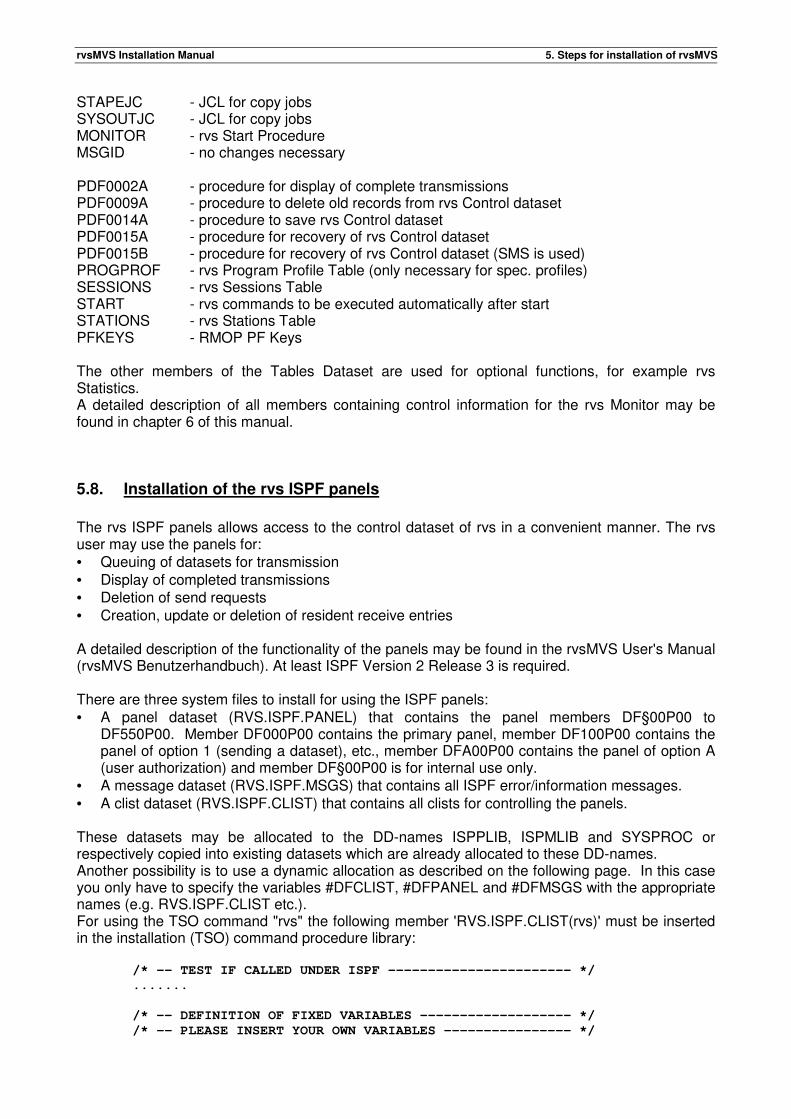
rvsMVS Installation Manual 5. Steps for installation of rvsMVS
STAPEJC - JCL for copy jobs SYSOUTJC - JCL for copy jobs MONITOR - rvs Start Procedure MSGID - no changes necessary PDF0002A - procedure for display of complete transmissions PDF0009A - procedure to delete old records from rvs Control dataset PDF0014A - procedure to save rvs Control dataset PDF0015A - procedure for recovery of rvs Control dataset PDF0015B - procedure for recovery of rvs Control dataset (SMS is used) PROGPROF - rvs Program Profile Table (only necessary for spec. profiles) SESSIONS - rvs Sessions Table START - rvs commands to be executed automatically after start STATIONS - rvs Stations Table PFKEYS - RMOP PF Keys The other members of the Tables Dataset are used for optional functions, for example rvs Statistics. A detailed description of all members containing control information for the rvs Monitor may be found in chapter 6 of this manual.
5.8. Installation of the rvs ISPF panels
The rvs ISPF panels allows access to the control dataset of rvs in a convenient manner. The rvs user may use the panels for: • Queuing of datasets for transmission • Display of completed transmissions • Deletion of send requests • Creation, update or deletion of resident receive entries A detailed description of the functionality of the panels may be found in the rvsMVS User's Manual (rvsMVS Benutzerhandbuch). At least ISPF Version 2 Release 3 is required. There are three system files to install for using the ISPF panels: • A panel dataset (RVS.ISPF.PANEL) that contains the panel members DF§00P00 to
DF550P00. Member DF000P00 contains the primary panel, member DF100P00 contains the panel of option 1 (sending a dataset), etc., member DFA00P00 contains the panel of option A (user authorization) and member DF§00P00 is for internal use only.
• A message dataset (RVS.ISPF.MSGS) that contains all ISPF error/information messages. • A clist dataset (RVS.ISPF.CLIST) that contains all clists for controlling the panels. These datasets may be allocated to the DD-names ISPPLIB, ISPMLIB and SYSPROC or respectively copied into existing datasets which are already allocated to these DD-names. Another possibility is to use a dynamic allocation as described on the following page. In this case you only have to specify the variables #DFCLIST, #DFPANEL and #DFMSGS with the appropriate names (e.g. RVS.ISPF.CLIST etc.). For using the TSO command "rvs" the following member 'RVS.ISPF.CLIST(rvs)' must be inserted in the installation (TSO) command procedure library: /* -- TEST IF CALLED UNDER ISPF ----------------------- */
.......
/* -- DEFINITION OF FIXED VARIABLES ------------------- */
/* -- PLEASE INSERT YOUR OWN VARIABLES ---------------- */
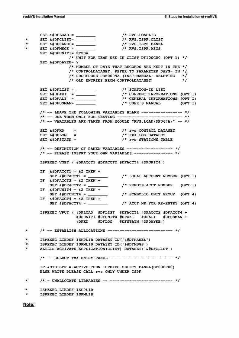
rvsMVS Installation Manual 5. Steps for installation of rvsMVS
SET &#DFLOAD = ________ /* RVS.LOADLIB
* SET &#DFCLIST= ________ /* RVS.ISPF.CLIST
* SET &#DFPANEL= ________ /* RVS.ISPF.PANEL
* SET &#DFMSGS = ________ /* RVS.ISPF.MSGS
SET &#DFUNIT1= SYSDA
/* UNIT FOR TEMP USE IN CLIST DF100C00 (OPT 1) */
SET &#DFDAYKE= 7
/* NUMBER OF DAYS THAT RECORDS ARE KEPT IN THE */
/* CONTROLDATASET. REFER TO PARAMETER DAYS= IN */
/* PROCEDURE PDF0009A (INST-MANUAL: DELETING */
/* OLD ENTRIES FROM CONTROLDATASET) */
SET &#DFLIST = ________ /* STATION-ID LIST
SET &#DFAKI = ________ /* CURRENT INFORMATIONS (OPT I)
SET &#DFALI = ________ /* GENERAL INFORMATIONS (OPT I)
SET &#DFUSMAN= ________ /* USER'S MANUAL (OPT I)
/* -- LEAVE THE FOLLOWING VARIABLES BLANK ----------------- */
/* -- USE THEM ONLY FOR TESTING --------------------------- */
/* -- VARIABLES ARE TAKEN FROM MODULE "RVS.LOAD(DF067A)" -- */
SET &#DFKD = /* rvs CONTROL DATASET
SET &#DFLOG = /* rvs LOG DATASET
SET &#DFSTATN = /* rvs STATIONS TABLE
/* -- DEFINITION OF PANEL VARIABLES ------------------- */
/* -- PLEASE INSERT YOUR OWN VARIABLES ---------------- */
ISPEXEC VGET ( #DFACCT1 #DFACCT2 #DFACCT4 #DFUNIT4 )
IF &#DFACCT1 = &Z THEN +
SET &#DFACCT1 = ________ /* LOCAL ACCOUNT NUMBER (OPT 1)
IF &#DFACCT2 = &Z THEN +
SET &#DFACCT2 = ________ /* REMOTE ACCT NUMBER (OPT 1)
IF &#DFUNIT4 = &Z THEN +
SET &#DFUNIT4 = ________ /* SYMBOLIC UNIT GROUP (OPT 4)
IF &#DFACCT4 = &Z THEN +
SET &#DFACCT4 = ________ /* ACCT NR FOR RR-ENTRY (OPT 4)
ISPEXEC VPUT ( #DFLOAD #DFLIST #DFACCT1 #DFACCT2 #DFACCT4 +
#DFUNIT1 #DFUNIT4 #DFAKI #DFALI #DFUSMAN +
#DFKD #DFLOG #DFSTATN #DFDAYKE )
* /* -- ESTABLISH ALLOCATIONS --------------------------- */
* ISPEXEC LIBDEF ISPPLIB DATASET ID('&#DFPANEL')
* ISPEXEC LIBDEF ISPMLIB DATASET ID('&#DFMSGS')
* ALTLIB ACTIVATE APPLICATION(CLIST) DATASET('&#DFCLIST')
/* -- SELECT rvs ENTRY PANEL -------------------------- */
IF &SYSISPF = ACTIVE THEN ISPEXEC SELECT PANEL(DF000P00)
ELSE WRITE PLEASE CALL rvs ONLY UNDER ISPF
* /* - UNALLOCATE LIBRARIES -- -------------------------- */
* ISPEXEC LIBDEF ISPPLIB
* ISPEXEC LIBDEF ISPMLIB
Note:
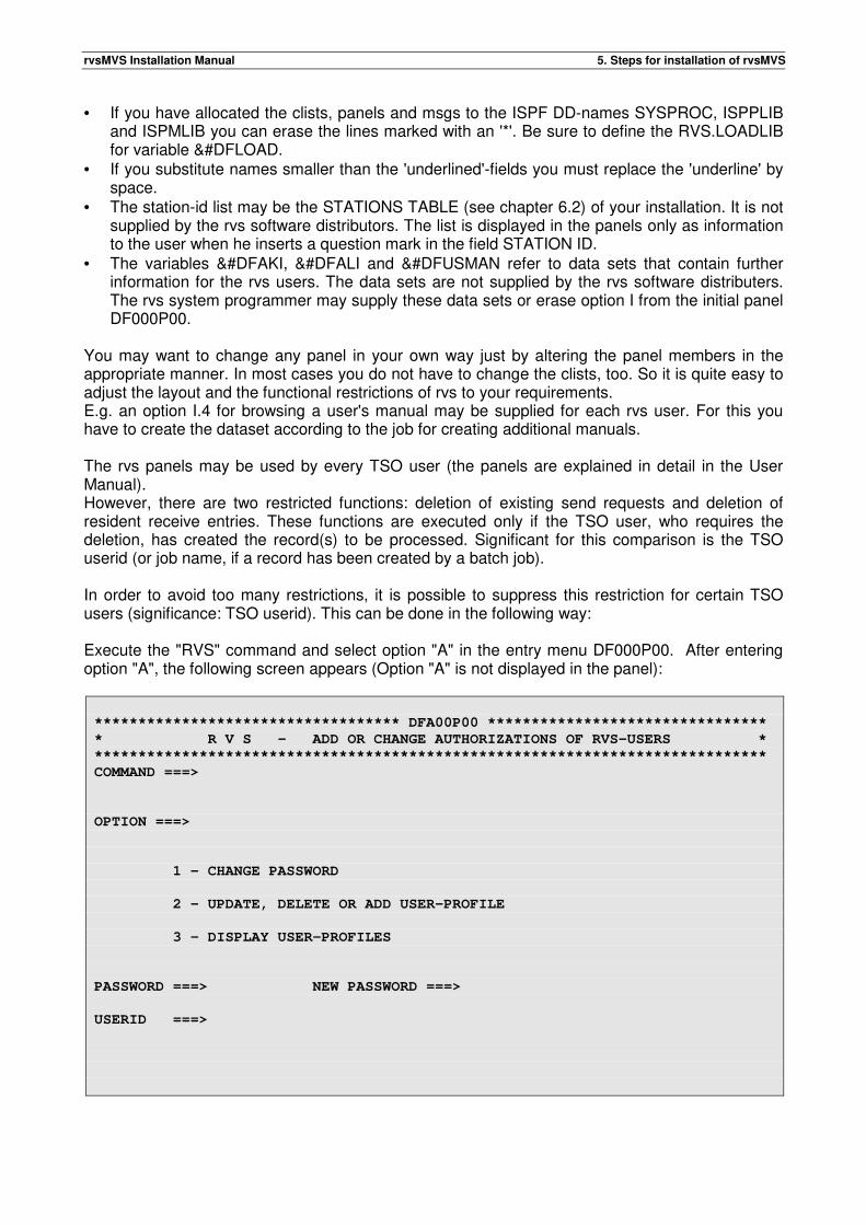
rvsMVS Installation Manual 5. Steps for installation of rvsMVS
• If you have allocated the clists, panels and msgs to the ISPF DD-names SYSPROC, ISPPLIB and ISPMLIB you can erase the lines marked with an '*'. Be sure to define the RVS.LOADLIB for variable &#DFLOAD.
• If you substitute names smaller than the 'underlined'-fields you must replace the 'underline' by space.
• The station-id list may be the STATIONS TABLE (see chapter 6.2) of your installation. It is not supplied by the rvs software distributors. The list is displayed in the panels only as information to the user when he inserts a question mark in the field STATION ID.
• The variables &#DFAKI, &#DFALI and &#DFUSMAN refer to data sets that contain further information for the rvs users. The data sets are not supplied by the rvs software distributers. The rvs system programmer may supply these data sets or erase option I from the initial panel DF000P00.
You may want to change any panel in your own way just by altering the panel members in the appropriate manner. In most cases you do not have to change the clists, too. So it is quite easy to adjust the layout and the functional restrictions of rvs to your requirements. E.g. an option I.4 for browsing a user's manual may be supplied for each rvs user. For this you have to create the dataset according to the job for creating additional manuals. The rvs panels may be used by every TSO user (the panels are explained in detail in the User Manual). However, there are two restricted functions: deletion of existing send requests and deletion of resident receive entries. These functions are executed only if the TSO user, who requires the deletion, has created the record(s) to be processed. Significant for this comparison is the TSO userid (or job name, if a record has been created by a batch job). In order to avoid too many restrictions, it is possible to suppress this restriction for certain TSO users (significance: TSO userid). This can be done in the following way: Execute the "RVS" command and select option "A" in the entry menu DF000P00. After entering option "A", the following screen appears (Option "A" is not displayed in the panel):
*********************************** DFA00P00 ********************************
* R V S - ADD OR CHANGE AUTHORIZATIONS OF RVS-USERS *
*****************************************************************************
COMMAND ===>
OPTION ===>
1 - CHANGE PASSWORD
2 - UPDATE, DELETE OR ADD USER-PROFILE
3 - DISPLAY USER-PROFILES
PASSWORD ===> NEW PASSWORD ===>
USERID ===>
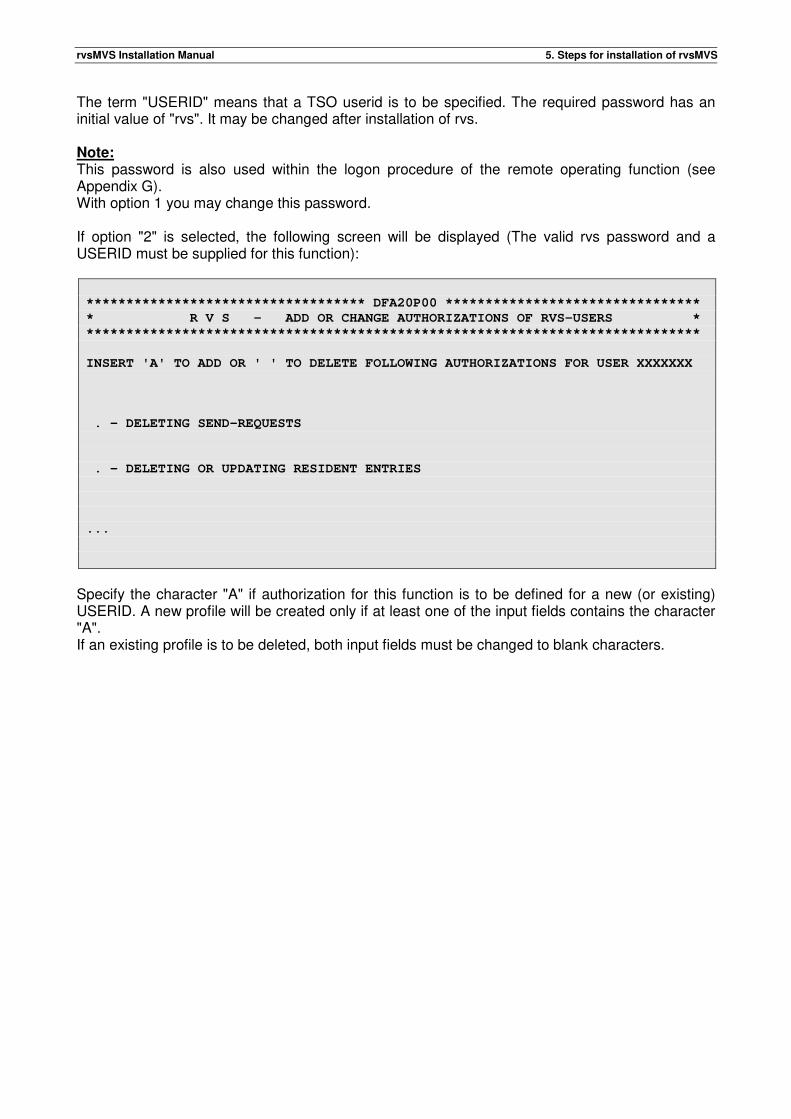
rvsMVS Installation Manual 5. Steps for installation of rvsMVS
The term "USERID" means that a TSO userid is to be specified. The required password has an initial value of "rvs". It may be changed after installation of rvs. Note: This password is also used within the logon procedure of the remote operating function (see Appendix G). With option 1 you may change this password. If option "2" is selected, the following screen will be displayed (The valid rvs password and a USERID must be supplied for this function):
*********************************** DFA20P00 ********************************
* R V S - ADD OR CHANGE AUTHORIZATIONS OF RVS-USERS *
*****************************************************************************
INSERT 'A' TO ADD OR ' ' TO DELETE FOLLOWING AUTHORIZATIONS FOR USER XXXXXXX
. - DELETING SEND-REQUESTS
. - DELETING OR UPDATING RESIDENT ENTRIES
...
Specify the character "A" if authorization for this function is to be defined for a new (or existing) USERID. A new profile will be created only if at least one of the input fields contains the character "A". If an existing profile is to be deleted, both input fields must be changed to blank characters.
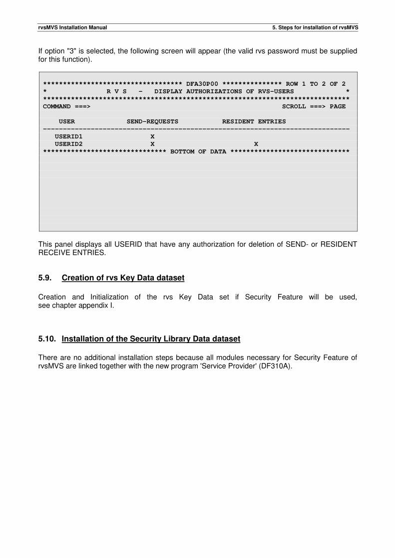
rvsMVS Installation Manual 5. Steps for installation of rvsMVS
If option "3" is selected, the following screen will appear (the valid rvs password must be supplied for this function).
*********************************** DFA30P00 *************** ROW 1 TO 2 OF 2
* R V S - DISPLAY AUTHORIZATIONS OF RVS-USERS *
*****************************************************************************
COMMAND ===> SCROLL ===> PAGE
USER SEND-REQUESTS RESIDENT ENTRIES
-----------------------------------------------------------------------------
USERID1 X
USERID2 X X
******************************* BOTTOM OF DATA ******************************
This panel displays all USERID that have any authorization for deletion of SEND- or RESIDENT RECEIVE ENTRIES.
5.9. Creation of rvs Key Data dataset
Creation and Initialization of the rvs Key Data set if Security Feature will be used, see chapter appendix I.
5.10. Installation of the Security Library Data dataset
There are no additional installation steps because all modules necessary for Security Feature of rvsMVS are linked together with the new program 'Service Provider' (DF310A).

rvsMVS Installation Manual 5. Steps for installation of rvsMVS
This page will be intentionally empty.
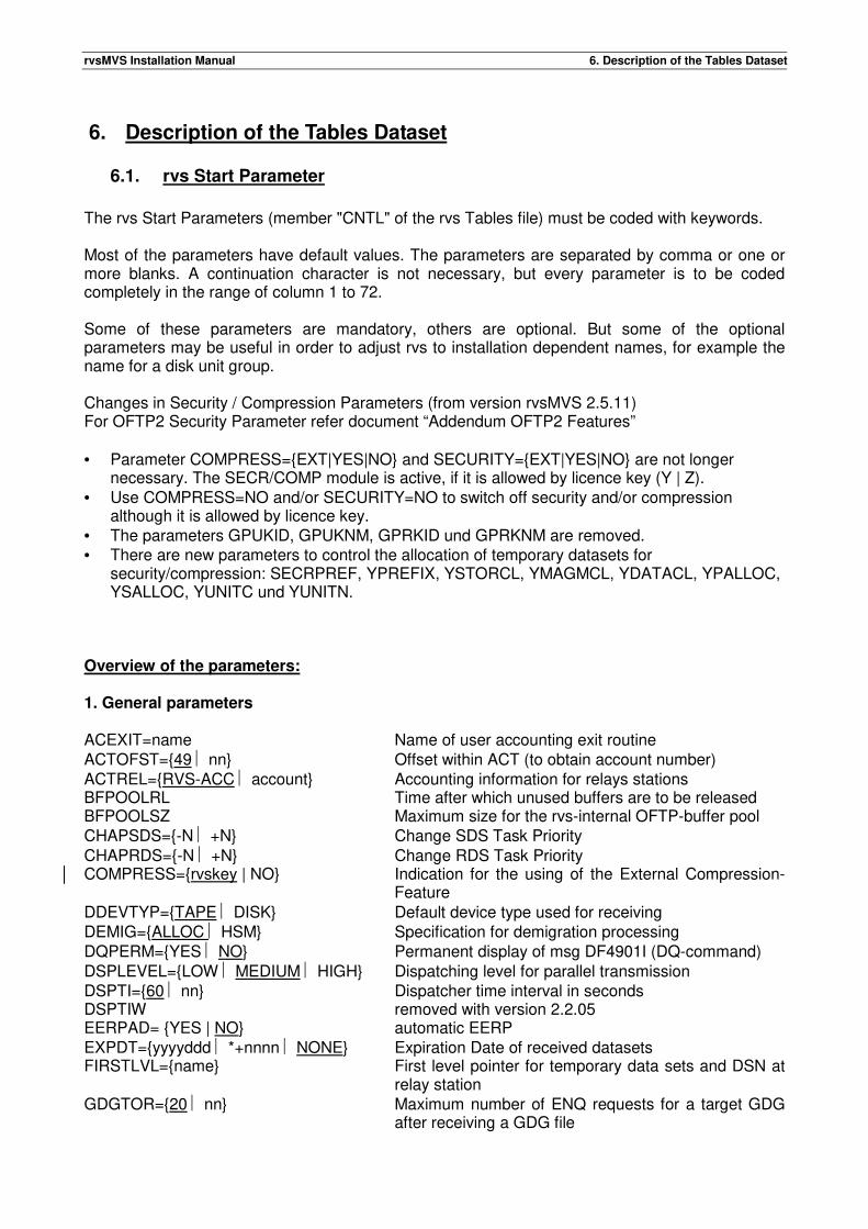
rvsMVS Installation Manual 6. Description of the Tables Dataset
6. Description of the Tables Dataset
6.1. rvs Start Parameter
The rvs Start Parameters (member "CNTL" of the rvs Tables file) must be coded with keywords. Most of the parameters have default values. The parameters are separated by comma or one or more blanks. A continuation character is not necessary, but every parameter is to be coded completely in the range of column 1 to 72. Some of these parameters are mandatory, others are optional. But some of the optional parameters may be useful in order to adjust rvs to installation dependent names, for example the name for a disk unit group. Changes in Security / Compression Parameters (from version rvsMVS 2.5.11) For OFTP2 Security Parameter refer document “Addendum OFTP2 Features” • Parameter COMPRESS={EXT|YES|NO} and SECURITY={EXT|YES|NO} are not longer
necessary. The SECR/COMP module is active, if it is allowed by licence key (Y | Z). • Use COMPRESS=NO and/or SECURITY=NO to switch off security and/or compression
although it is allowed by licence key. • The parameters GPUKID, GPUKNM, GPRKID und GPRKNM are removed. • There are new parameters to control the allocation of temporary datasets for
security/compression: SECRPREF, YPREFIX, YSTORCL, YMAGMCL, YDATACL, YPALLOC, YSALLOC, YUNITC und YUNITN.
Overview of the parameters: 1. General parameters ACEXIT=name Name of user accounting exit routine ACTOFST={49 nn} Offset within ACT (to obtain account number) ACTREL={RVS-ACC account} Accounting information for relays stations BFPOOLRL Time after which unused buffers are to be released BFPOOLSZ Maximum size for the rvs-internal OFTP-buffer pool CHAPSDS={-N +N} Change SDS Task Priority CHAPRDS={-N +N} Change RDS Task Priority COMPRESS={rvskey | NO} Indication for the using of the External Compression-
Feature DDEVTYP={TAPE DISK} Default device type used for receiving DEMIG={ALLOC HSM} Specification for demigration processing DQPERM={YES NO} Permanent display of msg DF4901I (DQ-command) DSPLEVEL={LOW MEDIUM HIGH} Dispatching level for parallel transmission DSPTI={60 nn} Dispatcher time interval in seconds DSPTIW removed with version 2.2.05 EERPAD= {YES | NO} automatic EERP EXPDT={yyyyddd *+nnnn NONE} Expiration Date of received datasets FIRSTLVL={name} First level pointer for temporary data sets and DSN at
relay station GDGTOR={20 nn} Maximum number of ENQ requests for a target GDG
after receiving a GDG file
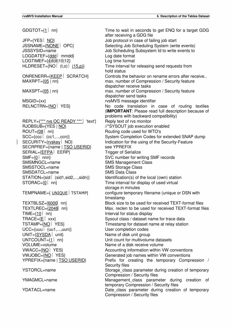
rvsMVS Installation Manual 6. Description of the Tables Dataset
GDGTOT={1 nn} Time to wait in seconds to get ENQ for a target GDG after receiving a GDG file
JFP={YES NO} Job protocol in case of failing job start JSSNAME={NONE OPC} Selecting Job Scheduling System (write events) JSSSYSID=name Job Scheduling Subsystem Id to write events to LOGDATEF={ddd mmdd} Log date format LOGTIMEF={4|6|8|10|12} Log time format HLDRESET={NO (t,o) (15,p)} Time interval for releasing send requests from
hold status ONRENERR={KEEP SCRATCH} Controls the behavior on rename errors after receive.. MAXRPT={05 | nn} max. number of Compression / Security feature
dispatcher receive tasks MAXSPT={05 | nn} max. number of Compression / Security feature
dispatcher send tasks MSGID={xx} rvsMVS message identifier RELNCTRN={NO YES} No code translation in case of routing textiles
(IMPORTANT: Please read full description because of problems with backward compatibility)
REPLY={*** rvs OC READY *** 'text'} Reply text of rvs monitor RJOBSUB={YES | NO} //*SYSOUT job execution enabled ROUT={08 nn} Routing code used for WTO's SCC={ccc (cc1,...,ccn)} System Completion Codes for extended SNAP dump SECURITY={rvskey NO} Indication for the using of the Security-Feature SECRPREF={name | TSO USERID} see YPREFIX SERIAL={EFPA EERP} Trigger of Serialize SMF={0 nnn} SVC number for writing SMF records SMSMNGCL=name SMS Management Class SMSSTOCL=name SMS Storage Class SMSDATCL=name SMS Data Class STATION={sid (sid1,sid2,...,sidn)} Identification(s) of the local (own) station STORAC={0 nn} Time interval for display of used virtual
storage in minutes TEMPNAME={ UNIQUE TSTAMP} configure temporary filename (unique or DSN with
timestamp TEXTBLSZ={6000 nn} Block size to be used for received TEXT-format files TEXTLREC={2048 nn} Max. reclen to be used for received TEXT-format files TIME={10 nn} Interval for status display TRACE={E xxx} Sysout class / dataset name for trace data TSTAMP={NO YES} Timestamp for dataset name at relay station UCC={uuu (uu1,...,uun)} User completion codes UNIT={SYSDA unit} Name of disk unit group UNTCOUNT={1 nn} Unit count for multivolume datasets VOLUME=volume Name of a disk receive volume VWACC={NO YES} Accounting information within VW conventions VWJOBC={NO YES} Generated job names within VW conventions YPREFIX={name | TSO USERID} Prefix for creating the temporary Compression /
Security files YSTORCL=name Storage_class parameter during creation of temporary
Compression / Security files YMAGMCL=name Management_class parameter during creation of
temporary Compression / Security files YDATACL=name Date_class parameter during creation of temporary
Compression / Security files
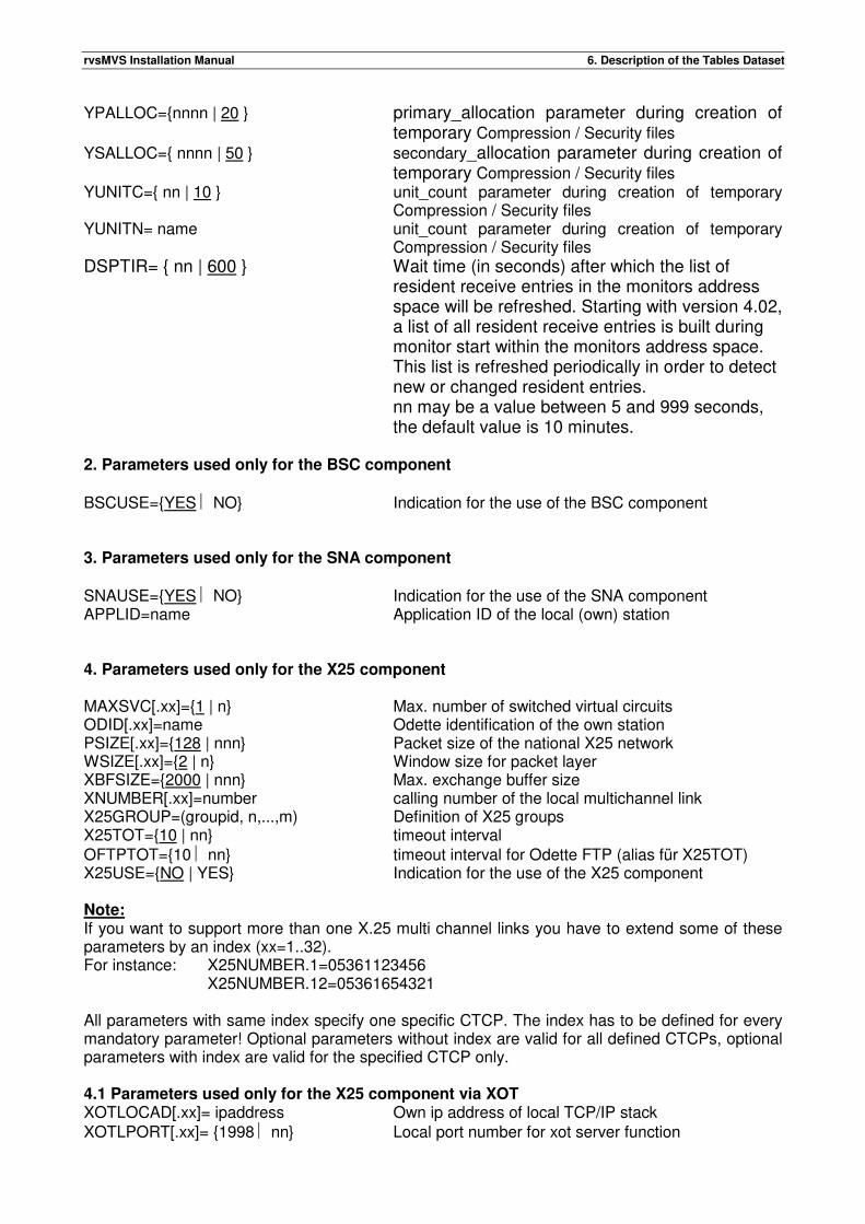
rvsMVS Installation Manual 6. Description of the Tables Dataset
YPALLOC={nnnn | 20 } primary_allocation parameter during creation of temporary Compression / Security files
YSALLOC={ nnnn | 50 } secondary_allocation parameter during creation of temporary Compression / Security files
YUNITC={ nn | 10 } unit_count parameter during creation of temporary Compression / Security files
YUNITN= name unit_count parameter during creation of temporary Compression / Security files
DSPTIR= { nn | 600 } Wait time (in seconds) after which the list of resident receive entries in the monitors address space will be refreshed. Starting with version 4.02, a list of all resident receive entries is built during monitor start within the monitors address space. This list is refreshed periodically in order to detect new or changed resident entries. nn may be a value between 5 and 999 seconds, the default value is 10 minutes.
2. Parameters used only for the BSC component BSCUSE={YES NO} Indication for the use of the BSC component 3. Parameters used only for the SNA component SNAUSE={YES NO} Indication for the use of the SNA component APPLID=name Application ID of the local (own) station 4. Parameters used only for the X25 component MAXSVC[.xx]={1 | n} Max. number of switched virtual circuits ODID[.xx]=name Odette identification of the own station PSIZE[.xx]={128 | nnn} Packet size of the national X25 network WSIZE[.xx]={2 | n} Window size for packet layer XBFSIZE={2000 | nnn} Max. exchange buffer size XNUMBER[.xx]=number calling number of the local multichannel link X25GROUP=(groupid, n,...,m) Definition of X25 groups X25TOT={10 | nn} timeout interval OFTPTOT={10 nn} timeout interval for Odette FTP (alias für X25TOT) X25USE={NO | YES} Indication for the use of the X25 component Note: If you want to support more than one X.25 multi channel links you have to extend some of these parameters by an index (xx=1..32). For instance: X25NUMBER.1=05361123456
X25NUMBER.12=05361654321 All parameters with same index specify one specific CTCP. The index has to be defined for every mandatory parameter! Optional parameters without index are valid for all defined CTCPs, optional parameters with index are valid for the specified CTCP only. 4.1 Parameters used only for the X25 component via XOT XOTLOCAD[.xx]= ipaddress Own ip address of local TCP/IP stack XOTLPORT[.xx]= {1998 nn} Local port number for xot server function
rvsMVS Installation Manual 6. Description of the Tables Dataset
XOTREMAD[.xx]= ipaddress ip address of xot router XOTRPORT[.xx]= {1998 nn} Port number of xot router XOTUSE[.xx]= {YES | NO} Indication for the use of the XOT component XOTNAME[.xx]= name (Reference-) name of the defined TCP/IP stack. 4.2 Parameters used only for the X25 component via NPSI XAPPLID[.xx]=name Application ID of the local (own) station XLUNAME[.xx]=name LU name of the local X.25 multichannel link XNUMCHCK[.xx]={YES | NO} checking of incoming call 5. Parameters used only for the LU62 component LU62USE={NO YES} Indication for the use of the LU62 component LU62MAX={0 nnn} max number of sessions LU62APPL=name Application ID of the local (own) station LU62MODE=(mode1,mode2,mode3) MODE-names for LU62 sessions ODID=name Odette identification of the own station X25TOT={10 nn} timeout interval OFTPTOT={10 nn} timeout interval for Odette FTP (alias für X25TOT) 6. Parameters used only for the TCP/IP component TCPUSE={NO YES} Indication for the use of the TCP/IP component TCPMAX[.xx]={50 nnn} max number of TCP/IP sessions TCPPORT[.xx]={3305 nn} Local port number for server function TCPLOCAD[.xx]=ipaddress Own ip address of local TCP/IP stack TCPNAME[.xx]=name Name of TCP/IP address space TCPPROD[.xx]={ IBM | INTERLINK } Name of the product of the TCP/IP stack to be used. TCPSTKID[.xx]= name (Reference-) name of the defined TCP/IP stack. ODID=name Odette identification of the own station X25TOT={10 nn} timeout interval for Odette FTP OFTPTOT={10 nn} timeout interval for Odette FTP (alias für X25TOT) Note: If you want to support more than one TCP/IP stack you have to extend some of these parameters by an index (xx=1..32). All parameters with the same index define one specific TCP/IP stack. If more than one TCP/IP stacks are to be used, the parameters TCPNAME and TCPSTKID are mandatory. If only one TCP/IP stack shall be used, all parameters may be coded without index. In this case, index 1 is assigned automatically. Additionally, parameter TCPSTKID is not mandatory in this case. 7. Parameters used only for the FTP component FTPUSE={NO YES} Indication for the use of the FTP component FTPMAX={50 nnn} max. number of parallel transmissions FTPPOLTI={60 nnn} FTP polling task time interval in seconds FTPPREF=name user prefix used for FTP file allocations (optional) ODID=name Odette identification of the own station
rvsMVS Installation Manual 6. Description of the Tables Dataset
8. Parameters used only for the remote operating function RMOPAPPL=name Application ID of the local (own) station Description of rvs Start Parameters in detail: General remark: Some of the rvs start parameters are used not only by the rvs monitor, but also by programs executed in different address spaces (for example rvs ISPF panels). Such programs obtain these values from the rvs control dataset, where the rvs monitor stores the current used parameter values during every run of rvs. Thus if parameter values are changed, they become active for all programs only after the next monitor start. ACEXIT=name Name of a user provided accounting exit routine. If no exit routine is installed, this parameter must be omitted. An accounting exit routine may be used to obtain accounting information about all executed transmissions. The interface for this exit is described in appendix A of this manual. A coding example is contained in appendix A also. Specification of this parameter is independent of the "SMF" parameter (see below). ACTOFST={49 nn} nn: value between 49 and 192 Some of the rvs programs (for example rvs ISPF panel programs) try to obtain accounting information from the ACT of the job (tso session), which executes these programs. The accounting information within this system control block is variable (depending on the specified accounting information within the JOB statement. This parameter specifies the displacement (base address: ACT-16), from where an account information shall be obtained by rvs programs (the first accounting parameter is placed at offset 49). For more details, see IBM macros "IEFAJCTB", "IEFAACTB". ACTREL={RVS-ACC account} Accounting information (max. 7 characters) for SMF records created by rvs and/or for user accounting exit, if installed) (see parameters "SMF", "ACEXIT" in this chapter). This accounting information is used for transmissions, where rvs works as a "relay" station, i.e. if rvs receives a dataset from a certain station and transmits the same dataset to another station (final receiver). APPLID=applid (only if SNA component rvs is used) Application ID of the local (own) station (1-8 alphanumeric characters). This name must be specified in an APPL statement of the local VTAM, see chapter "VTAM definitions". This name must be specified also in the rvs stations table of the remote station(s) (see chapter 6.2) and in the VTAM of the remote station(s) as a cross domain resource (see chapter "VTAM definitions"). If used, this name must be different from those specified for rvs start parameters RMOPAPPL, LU62APPL and XAPPLID. BFPOOLRL=ttt
rvsMVS Installation Manual 6. Description of the Tables Dataset
Parameter for rvs-internal OFTP buffer pool management. „ttt“ denotes the time in seconds, after which unused buffers of this pool are to be released (freed). Optional parameter. Default value: BFPOOLRL=20 BFPOOLSZ=sss Parameter for rvs-internal OFTP buffer pool management. „sss“ denotes the amount of storage in units of 1K, which is to be treated as the maximum size for the buffer pool. Default value: BFPOOLSZ=2000 BSCUSE={YES NO} Specification whether the BSC component is to be used or not. If "BSCUSE=NO" is specified, all commands related to the BSC component (for example commands for activation of BSC-lines or BSC-stations) will be rejected. CHAPSDS={+N -N} N: value between 0 and 9 Change the SDS Task Priority. Higher numbers increase the priority. CHAPRDS={+N -N} N: value between 0 and 9 Change the RDS Task Priority. Higher numbers increase the priority. COMPRESS={rvskey NO} It specifies how the Compression-Feature is used... Parameter COMPRESS={EXT|YES} is not longer necessary. The External Compression module is active, if it is allowed by licence key (Y). Use COMPRESS=NO to switch off compression although it is allowed by licence key. If "COMPRESS=NO" is specified, the External Compression will be rejected for all send requests of this installation. DDEVTYP={TAPE DISK} Default device type used for receiving. This default will always be used if a dataset is received and there are no further specifications for reception of this dataset (resident receive entry, see User's Manual). "DISK" means that the dataset will be received and kept on disk, "TAPE" means that the dataset is received on disk and will be copied to tape after reception (rvs generates and starts a batch job to copy the received file to tape). DEMIG={ALLOC HSM} Specification how demigration is to be done. DEMIG=ALLOC specifies that a migrated dataset is to be demigrated during allocation processing. The allocation routine will return control to rvs only after demigration of the file is complete. DEMIG=HSM specifies that rvs sends a demigration
rvsMVS Installation Manual 6. Description of the Tables Dataset
request to HSM. The transmission will then be cancelled by rvs, a send request will be set into a temporary HOLD status (see HLDRESET parameter). DEMIG=HSM should be specified if demigration processing takes longer times. In these situations rvs is not forced to wait until demigration is complete. Note that waiting for demigration processing within dynamic allocation implies that parallel allocation requests will also wait until demigration is complete, so parallel transmissions are impossible during this time. DQPERM={YES NO} Specification whether message DF4901I (display of all files which are still to be sent, DQ-command) is to be displayed as a highlighted, permanent message (DQPERM=YES) or not. If DQPERM=YES is specified, message DF4901I is changed whenever the send queue changes, this means message DF4901I always displays the actual values. If a change within the send queue is detected all messages DF4901I will be deleted and new ones will be displayed. This function uses the DOM-macro, thus MVS-SP 2.2.0 or a later MVS release is required for this because IBM has made an incompatible change for this macro within MVS-SP 2.2.0. DSPLEVEL={LOW MEDIUM HIGH} Dispatching level for parallel transmission of datasets with the same name. Started with rvsMVS rel 1.2.07 the internal ENQ name is expanded by the string USD.DUNUSD.TUNUSED, where
USD - name of the partner station DUNUSD - date stamp TUNUSED - timestamp.
These values will be substituted by actual values in the following manner:
USD if DSPLEVEL=MEDIUM or HIGH DUNUSD.TUNUSED if DSPLEVEL=HIGH
DSPTI={60 | nn} (Abbreviation: DTI) Dispatcher time interval in seconds. "nn" may be a value between 5 and 999. This value determines the time interval, after which the rvs dispatcher task becomes active. Every nn seconds, this task looks • if a previous entered "DIAL" command is to be executed or • if the rvs control dataset contains send requests, which are to be processed. If there is a send request for a certain station and if the connection to this station is defined as a • VTAM connection or • X25 connection or • LU62 connection or
• BSC line connection using the automatic dial function (See chapter 6.2, definition of stations table), the dispatcher task initiates processing of the send requests (if a send session or an autodial line is active and waiting for work). For X25 connections, an outgoing call is initiated in order to activate a switched virtual circuit. If the SNA component, the X25 component and no autodial is used in the installation, the maximum value (DSPTINTV=999) should be specified in order to avoid overhead (access to control dataset). The value of this parameter may be displayed / changed with the rvs command "DSPTI", see Operations Manual. EERPAD= { YES | NO }
rvsMVS Installation Manual 6. Description of the Tables Dataset
automatic send of EERP. It (AN-Record send) is controlled by parameter DIALOPT and station parameter EERPAD. If it is set to NO (default), rvsMVS will never do an active dial to send an EERP. If it is configured to YES the active dial behaviour depends on the station configuration (EERPAD and DIALOPT). See also new command „DD EERP“. EXPDT={yyyyddd *+nnnn NONE} With this parameter the expiration date of received datasets is determined.
"yyyy" - year, e.g.: 1998 "ddd" - day, e.g.: 365, this means 31.12.1998, or "nnnn" - number of days from the current day on, e.g. "*+30", current date = 1.12.1998,
expiration date=31.12.1998 If the parameter EXPDT is specified within a resident receive entry this value will be taken. With "NONE" no expiration date is used for dataset allocation. FIRSTLVL={name} (name: 1-8 characters, first must be alpha) This parameter is mandatory and is used as first level qualifier for temporary files and indirect file transfer using a relay station. It will be applied for temporary files only, if TEMPNAME=UNIQUE forcing creation of unique data set names for temporary files. In any case, i.e. independently of the applied value for TEMPNAME,
• it will be applied for transfers where rvsMVS is used as a relay station • and it will also be applied on temporary data set used for OFTP2 features. (O2WR)
For further details on the unique creation of individual data set names for temporary files, see setting TEMPNAME=UNIQUE. (We are referring to the rules followed in unique creation as blueprint.) FTPMAX=nnn This parameter specifies the maximal number of parallel FTP transmissions. nnn may be a value between 0 and 999. FTPPOLTI ={60 | nnn} This parameter is used only for the FTP component. Time interval of the FTP polling task (in seconds). "nnn" may be a value between 5 and 999. This value determines the time interval, after which the FTP Polling task becomes active. Every nnn seconds this task looks for FTP control files in the MVS system catalog. FTPPREF=name This parameter is used only for the FTP component. This parameter specifies the FTP user prefix name (1-18 characters). All FTP protocol files to be received by rvsMVS have to start with this prefix.
rvsMVS Installation Manual 6. Description of the Tables Dataset
The names of this FTP protocol files looks as following: prefix.FTPnn.sidoriginsidnext.siddestination.refnumber
prefix = value of FTPPREF parameter FTPnn = constant value depending on the protocol file sidorigin = origin station sid sidnext = sid of direct connected FTP station siddestination = destination station sid refnumber = FTP reference file number
The prefix must comply with the MVS DSName conventions. Example for a control file name (FTP information file):
• FTPPREF=MVSPREF, • origin station: AAA • connected FTP station: BBB • destination station: CCC
The corresponding protocol file name is: MVSPREF.FTPHD.AAABBB.CCC.F000123
Optional parameter (it is only used for following protocol files: information file, response file, end-to-end-response file). FTPUSE={NO | YES} This parameter is used only for the rvsFTP component. It indicates that this component is to be used by rvs. All parameters for this component must be given and a list may be found at the beginning of this section. GDGBASE={YES | NO} This parameter is used for SNA only. It indicates if GDG BASE should be created automatically or not. GDGTOR ={20 | nn} Maximum number of ENQ requests for a target GDG after receiving a GDG file. GDGTOT ={1 | nn} Time to wait in seconds to get ENQ for a target GDG after receiving a GDG file. HLDRESET={NO (t,o) (15,p)} This parameter is used for releasing dynamically send requests from hold status without involving any operating. When an abnormal end of transmission occurred and a send request has been put into hold status this parameter provides for an automatic retry of transmission after an appropriate
rvsMVS Installation Manual 6. Description of the Tables Dataset
time interval. This does not work if the send request has been put into hold status by operator. You may suppress this automation by specifying 'HLDRESET=NO'. HLDRESET=(t,o), t= time interval (5-999 min), o: option (e p (e=equal time interval,
p= progressing time interval)) When e(qual) time interval is specified a send request remains in hold status for t minutes before a next attempt of transmission may be done. When p(progressing) time interval is chosen the request remains in hold status for t times n minutes where n denotes to the number of unsuccessful attempts that have already been made. Examples: o=e, t=15: After an abnormal end the send request remains in hold status for fifteen minutes
before a new attempt may be done (regardless of the number of attempts). o=p, t=10: After the 1. unsuccessful attempt the send request remains in hold status for ten
minutes before a new attempt may be done. After the 2.try the entry remains in hold status for 20 minutes, then for 30 minutes etc.
IDEXIT=name Name of a user provided identification exit routine. If no identification exit routine is installed, this parameter must be omitted. This exit routine may be used to control (modify) the identification phase (exchange of station identifications) on switched BSC lines. The interface for this exit is described in appendix A of this manual. JFP={YES NO} Creation of a job protocol in case of failing automatic job start. The parameter "JFP=YES" provides a notification function if the rvs monitor cannot submit a specified job after reception of a file (for example a specified job dataset member does not exist or the job dataset cannot be allocated). If "JFP=YES" is specified, rvs submits the content of member "JFPJCL" of the rvs tables dataset instead of the job which has been specified in the resident receive entry (for more details see the description of member "JFPJCL" of the tables dataset in this chapter). Additionally the member "JFPJCL" of the tables dataset must be allocated with DD name "JFPJCL" within the rvs start procedure. JSSNAME={NONE OPC} Write events for this kind of job Scheduling Systems. If 'NONE' is specified, no events are written. Only OPC is realized so far. JSSSYSID=name max. 4 Chars Name of Job Scheduling Subsystem (e.g. OPCE) the event is routed to. If this parameter is specified within resident receive entry this field will be taken (see User Manual). LOGDATEF={ddd mmdd} This parameter is used to define the format of the date in log file. ddd – day of year (e.g. 038)
rvsMVS Installation Manual 6. Description of the Tables Dataset
mmdd – month day (e.g. 0207) LOGTIMEF={4|6|8|10|12} This parameter is used to define the format of the time in log file. 4 - HHMM (e.g. 1022) 6 - HHMMSS (e.g. 102225) 8 - HHMMSS and part of seconds (2 digits) 10 - HHMMSS and part of seconds (4 digits) 12 - HHMMSS and part of seconds (6 digits) LU62APPL=applid (only if LU6.2 component rvs is used) Application ID of the local (own) station (1-8 alphanumeric characters). This name must be specified in an APPL statement of the local VTAM, see chapter 3.4. This name must be specified also in the rvs stations table of the remote station(s) (see chapter 6.2). If used, this name must be different from those specified for the rvs start parameters RMOPAPPL, APPLID and XAPPLID. LU62MODE={(mode1[,mode2[,mode3]])} LOGMODE names for the LU62 sessions with the following order:
mode1 - mode name for low priority session mode2 - mode name for medium priority session mode3 - mode name for high priority session.
All names must be defined in the LOGMODE table of VTAM for the used application-ID. Note: • These names are the default values if no modes are defined in the station table entry of a
LU6.2 station. • These names must be exactly 8 characters long.
LU62MAX ={0 nnn} nn: value between 0 and 999 Max number of sessions for the LU62 component. LU62USE ={YES NO} This parameter is used only for the LU62 component. It indicates that this component is to be used by RVS. All parameters for this component must be given and a list may be found at the beginning of this section. MAXRPT={1 | nn} This parameter is used only for the Compression / Security feature component. It specifies the max. number of parallel comp/secr dispatcher receive tasks used by this component. "nn" may be a value between 1 and 99. MAXSPT={1 | nn}
rvsMVS Installation Manual 6. Description of the Tables Dataset
This parameter is used only for the Compression / Security feature component. It specifies the max. number of parallel comp/secr dispatcher send tasks used by this component. "nn" may be a value between 1 and 99.
MAXSVC[.xx]={1 n} This parameter is used only for the X25 component. It specifies the max. number of switched virtual circuits (SVC) to be used by this component. "n" may be a value between 1 and 99. The specified value must not be greater than the number of SVC's which are defined for the multichannel link. SVC's are normally defined within the X25VC macro (parameter LCN). To support more than one X.25 multi channel links you have to define this parameter for each X.25 multi channel (CTCP). MSGID=xx This parameter specifies the first two characters of the message id. ODID[.xx]={ value 'value' } This parameter is used only components which use the ODETTE FTP. It specifies the identification of the own station. Remark: ODETTE identifications will be defined and issued by the national automotive associations. Up to now it is not completely clear which organizations will do this work in the different countries. For the Federal Republic of Germany the following address should be consulted:
Verband der Automobilindustrie e.V. (VDA) Westendstraße 61 Postfach 170563 Kennwort: VDA-AVKD 4914 60079 Frankfurt Tel.: 069-97507-283 Fax: 069-97507-300 Mail: [email protected]
Registration and distribution of ODETTE ID is not free of charge. If you want to support more than one X.25 multi channel links it is possible to define different own ODETTE identifications for various X.25 multi channel links. Use the Index extension (xx=1..32) in this case. The ODID parameter without Index extension is valid for all defined X.25 multi channel links in your rvs Monitor. OFTPTOT={10 nn} This parameter is an alias for X25TOT. OFTPTOT should be used instead of X25TOT.
ONRENERR={KEEP SCRATCH} This parameter is used to control the behavior on rename errors after receiving a dataset. SCRATCH deletes the temporary dataset. KEEP tries to rename the temporary dataset to <FLP>.E.Mxx.Dxxxxx.Txxxxxx.Cxxxx.Cxxxx.
rvsMVS Installation Manual 6. Description of the Tables Dataset
PSIZE[.xx]={128 nnn} This parameter is used only for the X25 component. It specifies the packet size to be used. "nnn" may be one of the values 128, 256 or 512. This value must be the same as specified for parameter MAXPKTL of the X25VCCPT macro (NPSI generation). The specified value must be the same as the value used within the national X.25 network. To support more than one X.25 multi channel links you have to define this parameter for each X.25 multi channel (CTCP). The parameter without Index extension is valid for all defined X.25 multi cannel links in your rvs Monitor. RELNCTRN={NO YES} This parameter takes effect only if rvsMVS is a relay station. In ODETTE text mode, files are transmitted using ASCII codepage. If rvsMVS is a relay station content of a file was translated from ASCII to EBCDIC during receive and from EBCDIC to ASCII before send. This behavior can be disabled by setting RELNCTRN to YES. This can avoid corruption of the content caused by code translation. Enable or disable this feature takes only effect on new transmissions. IMPORTANT: If rvsMVS is a relay station and there is a text file to be routed without code conversion, it is not possible to downgrade to version 4.05.00 or previous. You can list such files with program DF0145E. Refer installation notes for more information. REPLY={*** rvs OC READY *** 'text'} Text of the rvs ready message on the console. When specifying 'text' the default message will be replaced by your text. The text must be enclosed within quotes and must not exceed 50 characters.
rvsMVS Installation Manual 6. Description of the Tables Dataset
RJOBSUB={YES | NO} This parameter indicates, if the remote job feature //*SYSOUT is enabled or not. RMOPAPPL=name This parameter is used only for the "remote operating function". This name must be specified in an APPL statement of the local VTAM. If the SNA component is used, this value must be different from the value specified within the rvs start parameter "APPLID". If this parameter is not coded, the "remote operating function" cannot be used. ROUT={08 nn} Routing code for rvs messages. Selectable between 1 and 15. The value of this parameter may be displayed / changed with the rvs command "ROUT", see Operations Manual. SCC={ccc (cc1,...,ccn)} Specification of system completion codes (in hex), for which an extended SNAP dump of the abended task will be taken. DD statement "rvsDUMP" (see rvs start procedure) is used to write the dump data. If other completion codes occur, only a short SNAP dump will be taken. Completion codes 0C1, 0C4, 0C6 and 0C7 will always result in an extended dump (except the same completion code occurs more than one time within one monitor run). SECRPREF={ name | TSO USERID } This parameter is used for the compression / security component only. This parameter specifies the user prefix name (1-8 characters). All internal compression / security temporary files’s names to be created by rvsMVS’s OFTP2-component will start with this prefix. SECRPREF may consist of more than 1 qualifier. SECURITY={rvskey NO} It specifies how the Security-Feature is used Parameter SECURITY={EXT|YES} is not longer necessary. The Security module is active, if it is allowed by licence key (Z) . Use SECURITY=NO to switch off security although it is allowed by licence key. If "SECURITY=NO" is specified, the Security Feature will be rejected for all send requests of this installation.
Attention!
The parameters GPUKID, GPUKNM, GPRKID und GPRKNM are removed.
SERIAL={EFPA EERP} Change Trigger of serialized send entries. EFPA - triggered by the ODETTE element End File Positive Answer EERP - triggered by the ODETTE element End to End Response
rvsMVS Installation Manual 6. Description of the Tables Dataset
SMF={0 nnn} "nnn" denotes the number of an installed User SVC (139-255), which may be used to write SMF records for rvs transmissions. "SMF=0" indicates that no User SMF records are to be written by the rvs monitor. An example of a SVC used for writing SMF records and the layout of the SMF records (created by the rvs monitor) are included in the source library of the installations tape (members ACTSVC, SMFREC). SMSMNGCL=name Name of the SMS management class. For more information see description of MGMTCLAS parameter in DD statement (JCL Reference). If the parameter MGMTCLAS is specified within a resident receive entry this value will be taken. With "NONE" the management class is not used for dataset allocation. SMSSTOCL=name Name of the SMS storage class. For more information see description of STORCLAS parameter in DD statement (JCL Reference). If the parameter STORCLAS is specified within a resident receive entry this value will be taken. With "NONE" the storage class is not used for dataset allocation. SMSDATCL=name Name of the SMS data class. For more information see description of DATACLAS parameter in DD statement (JCL Reference). If the parameter DATACLAS is specified within a resident receive entry this value will be taken. With "NONE" the data class is not used for dataset allocation. SNAUSE={YES NO} Specification whether the SNA component is to be used or not. If "SNAUSE=NO" is specified, all commands related to the SNA component (for example commands for activation of the SNA subtask or for SNA stations) will be rejected.
STATION={sid (sid,sid2)} Identification(s) of the own (local) station. Normally only one station identification must be specified ("sid": 3 alphanumeric characters). This is the station identification by rvs conventions. One additional identification ("sid2": max. 10 alphanumeric characters) is necessary if communication with the "DAKS" system (Daimler-Benz) is done. This is the station identification by DAKS conventions. Note: In order to avoid duplicate rvs station ids the Volkswagen AG has taken the responsibility to administer a central definition table. Please refer to the following address for receiving a new station id when you install rvs for the first time.
Volkswagen AG Abt. K-DOI-33
rvsMVS Installation Manual 6. Description of the Tables Dataset
Brieffach 1398/0 D-38436 Wolfsburg
Phone: +49-5631-9-27118, Mr. Strohmeyer
+49-5361-9-76484, Mr. Sekulla Fax: +49-5361-9-25500
The STATION parameter is mandatory. STORAC={0 nn} nn: value between 0 and 99) Specification of a time interval in minutes, after which the virtual storage currently used by the rvs monitor is listed (message DF2000P). If "STORAC=0" is specified, this display will be suppressed. The value of this parameter may be displayed / changed with the rvs command "STORAC, see Operation Manual. TCPLOCAD[.xx]=ipaddress Own ip-address of the local TCP/IP stack. This address will be used as source address when rvs acts as an initiator of connections. Specification of this parameter may be useful when the local TCP/IP stack includes more than one ip-address. If this parameter is not coded, the default ip-address of the local TCP/IP stack will be used (shown during initialization of the rvs-TCP/IP control task). With release 2.5.11, the specified address will also be used for the listen-task of the TCP/IP control task. Incoming connection requests will only be accepted if the connection request is sent to the specified ip-address. The ip-address for this parameter may be specified as an IPv4 address or an IPv6 address or as a symbolic name (dns-name). In case of dns-name, the name will be resolved to an ip-address. The protocol family (IPv4 vs. IPv6) used for the related line driver is determined in accordance to the given value. Remark: This parameter will be processed only in conjunction with parameter TCPPROD=IBM. TCPMAX[.xx]={50 nnn} nn: value between 50 and 999 Maximum number of sessions for the specified TCP/IP stack. If the index xx for the stack is not coded, the index value 1 will be automatically assigned. TCPNAME[.xx]=name An 8-byte character field set to the name of the TCP/IP address space used for this TCP/IP stack. For IBMs TCP/IP, the task’s name of the address space is to be taken. For the TCP/IP product of Interlink, the subsystem identifier (4-byte) must be defined. If this parameter is not specified and only one TCP/IP stack is used, the system derives a value from the configuration file of the TCP/IP installation. If the index xx for the stack is not coded, the index value 1 will be automatically assigned. TCPPORT[.xx]={3305 nn} nn: value between 0 and 32767 Local port number used for the TCP/IP server function of the used stack. After start of the specified TCP/IP stack, a server task is automatically started to look for incoming requests for
rvsMVS Installation Manual 6. Description of the Tables Dataset
connection. This server task only cares about requests for the specified port number. If the index xx for the stack is not coded, the index value 1 will be automatically assigned. The default value of 3305 is the port number recommended by the Odette organization which is officially registered by IANA, USA for the OFTP.
TCPPROD[.xx]={IBM INTERLINK} This parameter specifies the product name of the TCP/IP stack to be used. rvsMVS supports the stacks of IBM or INTERLINK. If the index xx for the stack is not coded, the index value 1 will be automatically assigned. TCPSTKID[.xx]=name Reference name for the specified TCP/IP stack. This name corresponds with the stations table parameter TCPIPADR. Name may be any alphanumeric string with a length of max. 8 bytes. If the index xx for the stack is not coded, the index value 1 will be automatically assigned. If more than one TCP/IP stack shall be used, this parameter must be coded for each stack. TCPUSE={YES NO} This parameter is used only for the TCP/IP component. It indicates that this component is to be used by rvs. In this case during start of the monitor, rvs will check if the other parameters related to the TCP/IP component are completely specified (or if default values are available). If one or more of these parameters are not specified and if no defaults are available, the TCP/IP component cannot be used. A list of all parameters for this component may be found at the beginning of this section. TEMPNAME={ UNIQUE TSTAMP} configure temporary / routing filename (unique or DSN with timestamp). TSTAMP – old format DSN.<TSTAMP> UNIQUE – new unique temporary file name
This will cause the application of a new pattern for temporary data sets. We are referring to the rules followed in unique creation as blueprint. The resulting pattern is: name.prefix.Mxx.Dyyddd.Thhmmss.Cxxxx.Cyyyy with • name taken from parameter FIRSTLV in CNTL • prefix depends on context of usage
Prefix Purpose
Also used for TEMPNAME= TIMESTAMP
T Temporary during transfer -
R Unloaded PDS -
RLS Temporary during transfer as relay station Yes
O2WR Temporary for OFTP2 features Yes
Z ComSecure
-
rvsMVS Installation Manual 6. Description of the Tables Dataset
S
Y
E Error in final rename / scratch -
• • Mxx: monitor number • Dyyddd: date stamp • Thhmmss: time stamp
• Cxxxx.Cyyyy: unique counter since monitor start TEXTBLSZ={6000 nn} nn: value between 9 and 32760
TEXTLREC={2048 nn} nn: value between 5 and 32756 Specification of a block size (TEXTBLSZ) or a maximum record length (TEXTLREC) to be used for files, which are to be received as ‚text-format‘ files. These files are always allocated with record format ‚variable blocked‘, but the values for maximum record length and block size may be specified different from the ODETTE recommendation. These parameters apply only for components, which use the ODETTE FTP as transmission protocol (LU6.2, X.25, TCP/IP). The value for TEXTBLSZ must be greater than (or equal to) TEXTLREC+4. If a text format file is to be received which includes records longer than the value of TEXTLREC, the transmission is terminated abnormally, the session is terminated with OFTP reason code 06 (invalid data). TIME={10 nn} nn: value between 1 and 99 Time interval in minutes, after which the rvs command "DS" is issued automatically (status display for all active BSC lines, SNA-, X.25- and TCP/IP-sessions of the rvs monitor). The value of this parameter may be displayed / changed with the rvs command "TIME“, see Operations Manual. TRACE={E pointer} Specification of a SYSOUT class or dataset name to which data (created by the rvs internal trace) will be written. If only one character is specified, rvs will treat this value as a SYSOUT class specification. If more than one character (max. 8) is specified, rvs treats this value as the first pointer of a dataset, which will be • allocated dynamically (if not existing) or • extended (DISP=MOD) (if already existing). at the time when the trace is started (rvs command "T sid", see Operations Manual. The complete name of this dataset is • pointer.LINExxx.TRACE if a BSC line is traced and "xxx" is the sub channel address of the
line, • pointer.sid.nm.TRACE if a SNA session to station "sid" is traced ("nm" denotes the session
type and number) • pointer.XMLU.TRACE if the X25 master LU session is traced • pointer.VCLUnnn.TRACE if the nnn.th virtual circuit LU (SVC) is traced (X25 component only) • pointer.sid.VCLUnnn.TRACE if the nnn.th virtual circuit LU (SVC) is traced but only data traffic
with station "sid" (X25 component only) • pointer.sid.TRACE if an FTP transmission to station „sid“ is traced If a dataset is allocated for trace output, the allocation uses the value from the start parameter "UNIT" for the symbolic unit group.
rvsMVS Installation Manual 6. Description of the Tables Dataset
For more information about this trace see the chapter "rvs Trace". UCC={uuu (uu1,...,uun)} Specification of user completion codes (in decimal), for which an extended SNAP dump of the abended task will be taken. DD statement "RVSDUMP" (see rvs start procedure) is used to write the dump data. If other completion codes occur, only a short SNAP dump will be taken. If the same user completion code occurs more than one time within one monitor run, an extended dump will be created only after the first occurrence of this abend code. UNIT={SYSDA unit} Symbolic name of a disk unit group which will be used by the rvs monitor to allocate datasets during reception if other specifications (resident receive entries, see User Manual) are not available. This parameter is exclusive with the "VOLUME" parameter. This unit group is also used when a partitioned organized dataset is queued for sending with means of the program DF080A00: The unloaded temporary dataset is allocated on a volume of this unit group. UNTCOUNT={1 nn} Unit count for multivolume datasets. Starting with version 2.2.05, rvs supports multivolume datasets when files are to be received. The unit count specifies the maximum number of volumes to be used for files which are to be received. ‚nn‘ may be a value from 1 up to 20. This parameter is only used for files to be received on work volumes. It is ignored when files are to be received on special volumes or when existing files are to be replaced. The default value (UNTCOUNT=1) is set because of compatibility with elder rvs versions, but it is recommended to specify the maximum value (UNTCOUNT=20). VOLUME=volume Name of a disk volume which will be used by the rvs monitor to allocate datasets during receive if other specifications (resident receive entries, see User Manual) are not available. This parameter is exclusive with the "UNIT" parameter. If both, the VOLUME and UNIT parameter are specified, the UNIT parameter will be ignored. Specification of this parameter causes the rvs monitor to receive all datasets on the specified disk volume with following exceptions: A resident receive entry (see User Manual) is available and a different receive volume is specified within this entry. The sending station has specified a different receive volume (remote options, see User Manual) and the local (own) station has authorized the sending (remote) station for this (for authorizations see description of the rvs Stations Table within this manual). VWACC={NO YES} Accounting information within VW conventions VWJOBC={NO | YES}
rvsMVS Installation Manual 6. Description of the Tables Dataset
"VWJOBC=YES": generated job names are within VW conventions. Job names are generated if
• a received dataset shall be copied from disk to tape • a received dataset shall be copied to a SYSOUT class • a tape dataset (queued for sending) shall be copied from tape to disk before
transmission. "VWJOBC=NO": the job name specified in member "JOBCARD" of the rvs Tables dataset (used
for the above mentioned copy jobs, see chapter 6) will not be changed. WSIZE[.xx]={2 n} This parameter is used only for the X25 component. It specifies the window size to be used on packet layer. If LLC4 (GATE) is used (the X25 component of rvs uses this function), the values for parameters MAXPKTL and VWINDOW of macro X25VCCPT are not used. Thus the value for this start parameter of rvs must be the same as the value which is specified for the VWINDOW parameter of the X25VCCPT macro (NPSI generation). Remark: This value must be the same as defined by the national X.25 network company for the multichannel link. To support more than one X.25 multi channel links you have to define this parameter for each X.25 multi channel (CTCP). The parameter without Index extension is valid for all defined X.25 multi cannel links in your rvs Monitor. X25GROUP=(groupid,n,..,m) groupid = max. 8 characters n,..,m = list of CTCP numbers which should be comprised in this group This parameter is used to define an X.25 group to comprise several X.25 multi channel links. Use this parameter another time to define more than one X.25 group. It is possible to use the same CTCP number in various groups. The 'groupid' may be referred to by partner stations table entries in parameter X25NUM. (See also chapter 6.2.4 of this manual.) X25TOT={10 nn} This parameter is used only components which use the ODETTE FTP. It specifies the timeout interval (in minutes) which is used by the ODETTE file transfer protocol to control time out situations. "nn" may be a value between 1 and 255. X25USE={YES NO} This parameter is used only for the X25 component. It indicates that this component is to be used by rvs. In this case during start of the monitor, rvs will check if the other parameters related to the X.25 component are completely specified (or if default values are available). If one or more of these parameters are not specified and if no defaults are available, the X25 component cannot be used. A list of all parameters for the X25 component may be found at the beginning of this section. XAPPLID[.xx]=name This parameter is used only for the X25 component. This name must be specified in an APPL statement of the local VTAM. If the SNA component or the remote operating function (or both) is used, this value must be different from the values specified within the rvs start parameters "APPLID" and "RMOPAPPL". This application id is used to establish sessions between rvs and the
rvsMVS Installation Manual 6. Description of the Tables Dataset
NPSI. To support more than one X.25 multi channel links you have to define this parameter for each X.25 multi channel (CTCP). XBFSIZE={2000 nnn} This parameter is used only for the X25 component. It specifies the max. exchange buffer size to be used by rvs, "nnn" may be a value between 128 and 32000. This parameter corresponds with two other values: • Parameter "LBLKSIZE" within the rvs stations table for stations defined to use the X.25
network (stations table parameter "ACCESMET=X25"). If the value of parameter "LBLKSIZE" is greater than the value of parameter "XBFSIZE", the value for "LBLKSIZE" will be reduced to the value of "XBFSIZE" automatically during start of rvs. Thus the value of parameter "XBFSIZE" is always the maximum size of exchange buffers used for X25 stations.
• For the set of switched virtual circuits to be used by rvs, a definition of a "switched major node" within VTAM is required. The value for the "MAXDATA" parameter of the "PU" macro within the switched major node definition must always be greater than the value for the rvs start parameter "XBFSIZE".
XLUNAME[.xx]=name This parameter is used only for the X25 component. It specifies the name of the logical unit which is used to establish a control session between rvs (application as specified within the "XAPPLID" parameter) and the NPSI. "name" must be the same name as specified for parameter "LUNAME" of macro "X25MCH" during NPSI generation. To support more than one X.25 multi channel links you have to define this parameter for each X.25 multi channel (CTCP). XNUMBER[.xx]=number This parameter is used only for the X25 component. It specifies the calling number of the local X.25 multichannel link. This number is used when outgoing calls are initiated by rvs. To support more than one X.25 multi channel links you have to define this parameter for each X.25 multi channel (CTCP).
XNUMCHCK[.xx]={YES NO} This parameter is used only for the X25 component. It indicates whether a received X25 number is to be checked with the number specified within the stations table (parameter X25NUM) in case of an incoming call from a certain station (XNUMCHCK=YES) or not. If XNUMCHCK=YES is specified and the x25 number (received from a certain station by an incoming call) does not match the number which is specified for this station within the rvs stations table, activation of the session will be rejected, this means the received ODETTE data unit "SSID" will be responded by an "ESID" data unit (end of session) with reason code 03 (user code not known or invalid). See also corresponding parameter XNUMCHCK of rvs stations table (x.25 entry) To support more than one X.25 multi channel links you have to define this parameter for each X.25 multi channel (CTCP). The parameter without Index extension is valid for all defined X.25 multi channel links in your rvs Monitor. XOTLOCAD[.xx]=ipaddress Own ip-address of the local TCP/IP stack. The specified address will be used by the XOT listener task to accept incoming connections from XOT capable hardware (e.g. XOT- Router).
rvsMVS Installation Manual 6. Description of the Tables Dataset
The ip-address for this parameter may be specified as an IPv4 address or an IPv6 address or as a symbolic name (dns-name). In case of dns-name, the name will be resolved to an ip-address. The protocol family (IPv4 vs. IPv6) used for the related line driver is determined in accordance to the given value. If this parameter is not coded, the default ip-address of the local TCP/IP stack will be used. XOTLPORT[.xx]={1998 nn} nn: value between 0 and 32767 Local port number used for the XOT server function. The specified number will be used by the XOT listener task to accept incoming connections from XOT capable hardware (e.g. XOT- Router). The default value of 1998 is the port number recommended by the XOT- RFC 1613. If the index xx is not coded, the index value 1 will be automatically assigned. XOTNAME[.xx]=name Reference name for the specified TCP/IP stack. If the parameter is not specified the default TCP/IP stack will be used. The Name may be any alphanumeric string with a length of max. 8 bytes. If the index xx for the stack is not coded, the index value 1 will be automatically assigned. XOTREMAD[.xx]=ipaddress Remote ip-address of the XOT capable hardware (e.g. XOT- Router), used by the XOT communication task to establish a connection. The ip-address for this parameter may be specified as an IPv4 address or an IPv6 address or as a symbolic name (dns-name). In case of dns-name, the name will be resolved to an ip-address. The given value must conform to the protocol family (IPv4 vs. IPv6) used for the related line driver. XOTRPORT[.xx]={1998 nn} nn: value between 0 and 32767 Remote port number of the XOT capable hardware (e.g. XOT- Router), used by the XOT communication task to establish a connection. The default value of 1998 is the port number recommended by the XOT- RFC 1613. If the index xx is not coded, the index value 1 will be automatically assigned. XOTUSE={YES NO} This parameter is used for the X25 component only. It indicates the use of X.25 via XOT (in case of YES) or X.25 via NPSI (in case of NO) as X.25 network.
YPREFIX={ name | TSO USERID } This parameter is used for the compression / security component only. This parameter specifies the user prefix name (1-7 characters). All internal compression / security temporary files to be created by rvsMVS’s ComSecure-component will start with this prefix.. YSTORCL=name
This parameter is used for the security component only. This parameter specifies the name of the SMS storage class used for the allocation of the compression / security temporary files. If not
rvsMVS Installation Manual 6. Description of the Tables Dataset
defined, the value of the parameter SMSSTOCL will be used. If both parameters (YSTORCL and SMSSTOCL) are not defined, the default value is “NONE”. With value „NONE“ no storage class is used.
YMAGMCL=name
This parameter is used for the security component only. This parameter specifies the name of the SMS management class used for the allocation compression / security temporary files. If not defined, the value of the parameter SMSMNGCL will be used. If both parameters (YMAGMCL and SMSMNGCL) are not defined, the default value is “NONE”. With value „NONE“ no management class is used.
YDATACL=name
This parameter is used for the security component only. This parameter specifies the name of the SMS data class used for the allocation Compression / Security temporary files. If not defined, the value of parameter SMSDATCL is used. If both parameters (YDATACL and SMSDATCL) are not defined, the default value is “NONE”. With value „NONE“ no data class is used.
YPALLOC={nnnn | 20 }
This parameter is used for the security component only. This parameter specifies the primary allocation in cylinders for allocation Compression / Security temporary files. ‚nnnn‘ may be a value from 1 up to 9999.
YSALLOC={ nnnn | 50 }
This parameter is used for the security component only. This parameter specifies the secondary allocation in cylinders for allocation Compression / Security temporary files. ‚nnnn‘ may be a value from 1 up to 9999.
YUNITC={ nn | 10 }
This parameter is used for the security component only. This parameter specifies the unit count for multivolume datasets used for allocation Compression / Security temporary files. ‚nn‘ may be a value from 1 up to 20. If not defined, then the value of parameter UNTCOUNT is used. If both parameters (YUNITC and UNTCOUNT) are not defined, the default value is 10.
YUNITN=name
This parameter is used for the security component only. This parameter specifies the symbolic name of a disk unit group which will be used for allocation Compression / Security temporary files. If not defined, then the value of parameter UNIT is used. If both parameters (YUNITN and UNIT) are not defined, the default value is SYSDA.
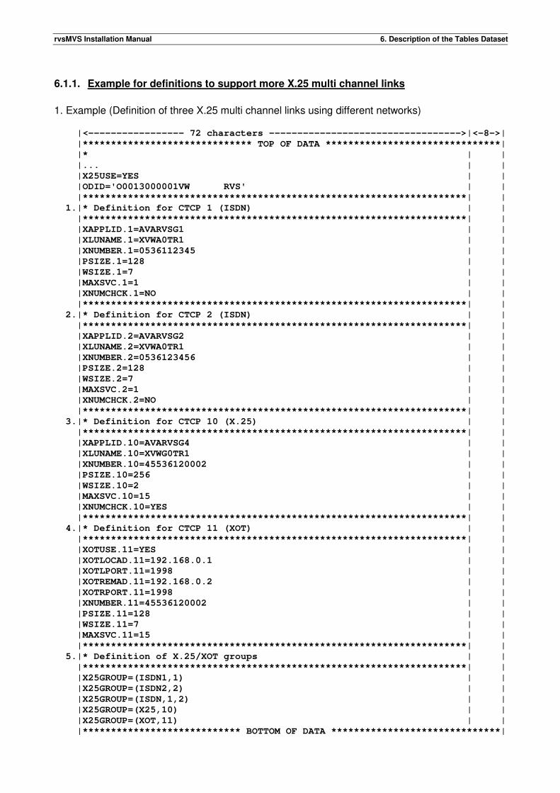
rvsMVS Installation Manual 6. Description of the Tables Dataset
6.1.1. Example for definitions to support more X.25 multi channel links
1. Example (Definition of three X.25 multi channel links using different networks) |<----------------- 72 characters ---------------------------------->|<-8->|
|****************************** TOP OF DATA *******************************|
|* | |
|... | |
|X25USE=YES | |
|ODID='O0013000001VW RVS' | |
|********************************************************************| |
1.|* Definition for CTCP 1 (ISDN) | |
|********************************************************************| |
|XAPPLID.1=AVARVSG1 | |
|XLUNAME.1=XVWA0TR1 | |
|XNUMBER.1=0536112345 | |
|PSIZE.1=128 | |
|WSIZE.1=7 | |
|MAXSVC.1=1 | |
|XNUMCHCK.1=NO | |
|********************************************************************| |
2.|* Definition for CTCP 2 (ISDN) | |
|********************************************************************| |
|XAPPLID.2=AVARVSG2 | |
|XLUNAME.2=XVWA0TR1 | |
|XNUMBER.2=0536123456 | |
|PSIZE.2=128 | |
|WSIZE.2=7 | |
|MAXSVC.2=1 | |
|XNUMCHCK.2=NO | |
|********************************************************************| |
3.|* Definition for CTCP 10 (X.25) | |
|********************************************************************| |
|XAPPLID.10=AVARVSG4 | |
|XLUNAME.10=XVWG0TR1 | |
|XNUMBER.10=45536120002 | |
|PSIZE.10=256 | |
|WSIZE.10=2 | |
|MAXSVC.10=15 | |
|XNUMCHCK.10=YES | |
|********************************************************************| |
4.|* Definition for CTCP 11 (XOT) | |
|********************************************************************| |
|XOTUSE.11=YES | |
|XOTLOCAD.11=192.168.0.1 | |
|XOTLPORT.11=1998 | |
|XOTREMAD.11=192.168.0.2 | |
|XOTRPORT.11=1998 | |
|XNUMBER.11=45536120002 | |
|PSIZE.11=128 | |
|WSIZE.11=7 | |
|MAXSVC.11=15 | |
|********************************************************************| |
5.|* Definition of X.25/XOT groups | |
|********************************************************************| |
|X25GROUP=(ISDN1,1) | |
|X25GROUP=(ISDN2,2) | |
|X25GROUP=(ISDN,1,2) | |
|X25GROUP=(X25,10) | |
|X25GROUP=(XOT,11) | |
|**************************** BOTTOM OF DATA ******************************|

rvsMVS Installation Manual 6. Description of the Tables Dataset
1./2. Definition of two X.25 multi channel links which should use ISDN - the parameters to
describe CTCP 1 and CTCP 2 are specified by index 1 / index 2. 3. Definition of an X.25 multi channel link which should use X.25 as network. The index
number to specify the CTCP is 10. 4. Definition of an XOT link which should use X.25 as network. The index number to specify
the CTCP is 11. 5. Definition of X.25 groups to comprise various X.25 multi channel links. For instance
'ISDN' specifies a group consisting of CTCP 1 and CTCP 2; 'X25' specifies a group consisting of CTCP 10.

rvsMVS Installation Manual 6. Description of the Tables Dataset
This page will be intentionally empty.
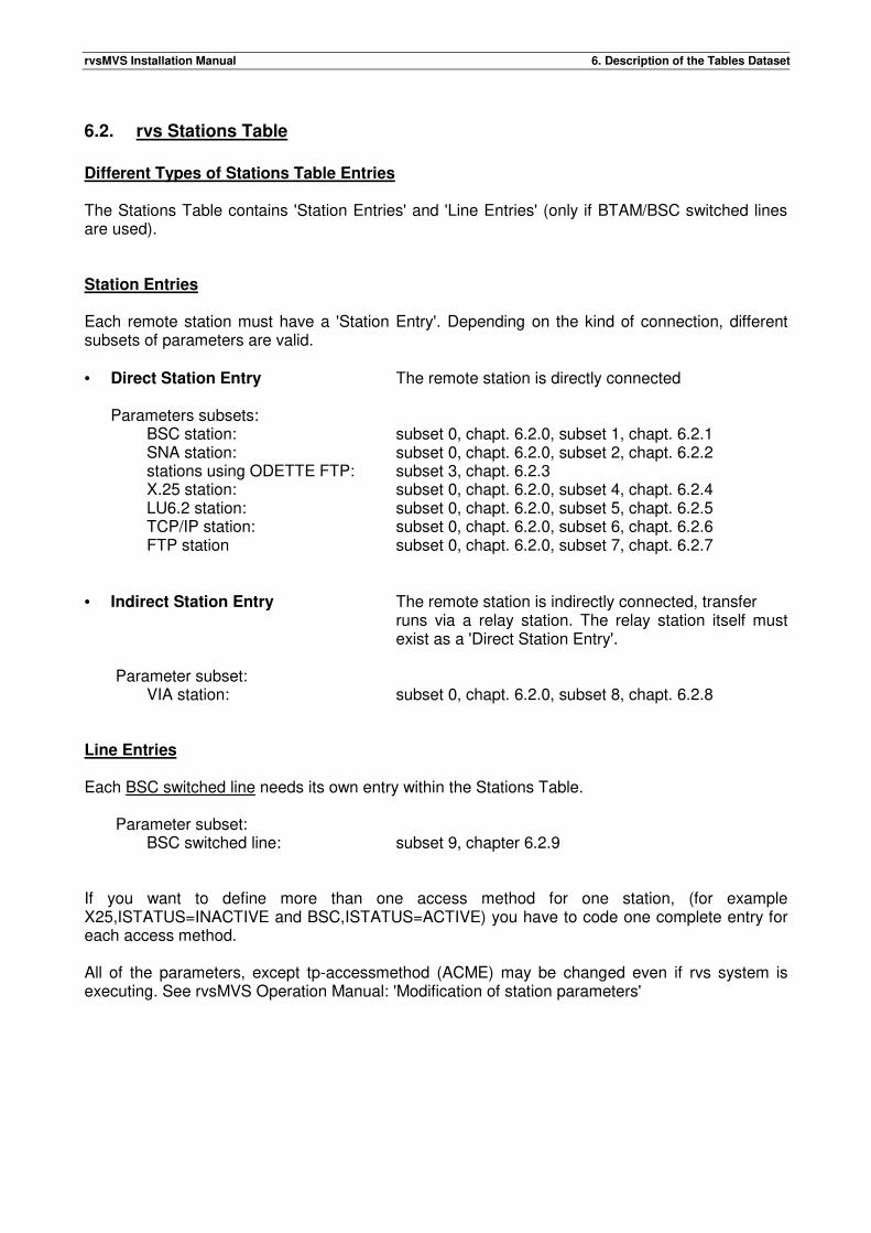
rvsMVS Installation Manual 6. Description of the Tables Dataset
6.2. rvs Stations Table
Different Types of Stations Table Entries The Stations Table contains 'Station Entries' and 'Line Entries' (only if BTAM/BSC switched lines are used). Station Entries Each remote station must have a 'Station Entry'. Depending on the kind of connection, different subsets of parameters are valid. • Direct Station Entry The remote station is directly connected
Parameters subsets: BSC station: subset 0, chapt. 6.2.0, subset 1, chapt. 6.2.1 SNA station: subset 0, chapt. 6.2.0, subset 2, chapt. 6.2.2 stations using ODETTE FTP: subset 3, chapt. 6.2.3 X.25 station: subset 0, chapt. 6.2.0, subset 4, chapt. 6.2.4 LU6.2 station: subset 0, chapt. 6.2.0, subset 5, chapt. 6.2.5 TCP/IP station: subset 0, chapt. 6.2.0, subset 6, chapt. 6.2.6 FTP station subset 0, chapt. 6.2.0, subset 7, chapt. 6.2.7
• Indirect Station Entry The remote station is indirectly connected, transfer
runs via a relay station. The relay station itself must exist as a 'Direct Station Entry'.
Parameter subset: VIA station: subset 0, chapt. 6.2.0, subset 8, chapt. 6.2.8 Line Entries Each BSC switched line needs its own entry within the Stations Table. Parameter subset:
BSC switched line: subset 9, chapter 6.2.9 If you want to define more than one access method for one station, (for example X25,ISTATUS=INACTIVE and BSC,ISTATUS=ACTIVE) you have to code one complete entry for each access method. All of the parameters, except tp-accessmethod (ACME) may be changed even if rvs system is executing. See rvsMVS Operation Manual: 'Modification of station parameters'
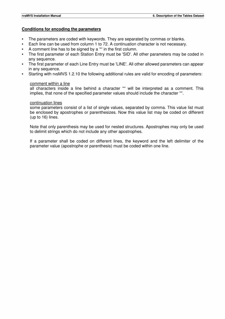
rvsMVS Installation Manual 6. Description of the Tables Dataset
Conditions for encoding the parameters • The parameters are coded with keywords. They are separated by commas or blanks. • Each line can be used from column 1 to 72. A continuation character is not necessary. • A comment line has to be signed by a '*' in the first column. • The first parameter of each Station Entry must be 'SID'. All other parameters may be coded in
any sequence. • The first parameter of each Line Entry must be 'LINE'. All other allowed parameters can appear
in any sequence. • Starting with rvsMVS 1.2.10 the following additional rules are valid for encoding of parameters:
comment within a line all characters inside a line behind a character '*' will be interpreted as a comment. This implies, that none of the specified parameter values should include the character '*'.
continuation lines some parameters consist of a list of single values, separated by comma. This value list must be enclosed by apostrophes or parenthesizes. Now this value list may be coded on different (up to 16) lines.
Note that only parenthesis may be used for nested structures. Apostrophes may only be used to delimit strings which do not include any other apostrophes.
If a parameter shall be coded on different lines, the keyword and the left delimiter of the parameter value (apostrophe or parenthesis) must be coded within one line.
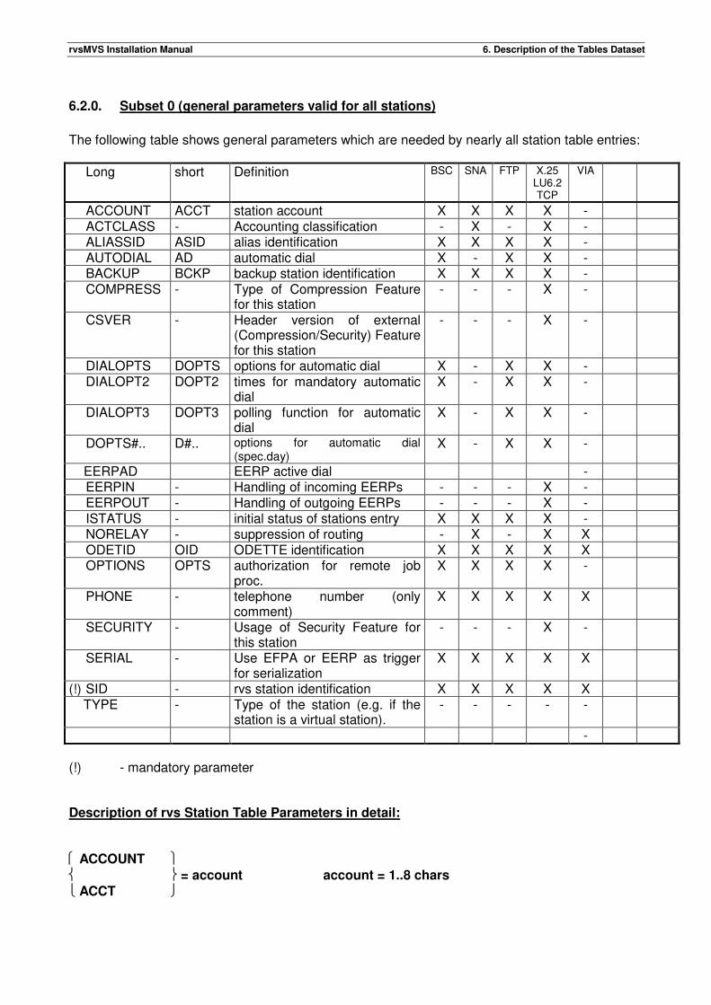
rvsMVS Installation Manual 6. Description of the Tables Dataset
6.2.0. Subset 0 (general parameters valid for all stations)
The following table shows general parameters which are needed by nearly all station table entries:
Long short Definition BSC SNA FTP X.25 LU6.2 TCP
VIA
ACCOUNT ACCT station account X X X X - ACTCLASS - Accounting classification - X - X - ALIASSID ASID alias identification X X X X - AUTODIAL AD automatic dial X - X X - BACKUP BCKP backup station identification X X X X - COMPRESS - Type of Compression Feature
for this station - - - X -
CSVER - Header version of external (Compression/Security) Feature for this station
- - - X -
DIALOPTS DOPTS options for automatic dial X - X X - DIALOPT2 DOPT2 times for mandatory automatic
dial X - X X -
DIALOPT3 DOPT3 polling function for automatic dial
X - X X -
DOPTS#.. D#.. options for automatic dial (spec.day)
X - X X -
EERPAD EERP active dial - EERPIN - Handling of incoming EERPs - - - X - EERPOUT - Handling of outgoing EERPs - - - X - ISTATUS - initial status of stations entry X X X X - NORELAY - suppression of routing - X - X X ODETID OID ODETTE identification X X X X X OPTIONS OPTS authorization for remote job
proc. X X X X -
PHONE - telephone number (only comment)
X X X X X
SECURITY - Usage of Security Feature for this station
- - - X -
SERIAL - Use EFPA or EERP as trigger for serialization
X X X X X
(!) SID - rvs station identification X X X X X TYPE - Type of the station (e.g. if the
station is a virtual station). - - - - -
-
(!) - mandatory parameter Description of rvs Station Table Parameters in detail: ACCOUNT = account account = 1..8 chars
ACCT
rvsMVS Installation Manual 6. Description of the Tables Dataset
Account of remote station. This value is taken when a dataset is to be received and no account is transmitted by the sender and no RR entry account exists. No default value. ACTCLASS=(type,distance) Account classification for the connection with the remote station. This parameter is used only if the rvs start parameter SMF is also coded. The classification consists of the line type (L=leased, S=switched) and a specification for the distance (L=local, F=far distance, I=international). Default: ACTCLASS=(S,L). For more information see description of the SMF accounting record in the rvs source library (RVS.SOURCE).
ADDRESS ='text-string' text-string = max. 20 chars
ADDR Address of the station. Optional parameter. The text-string must be put into quotes. Within the quotes all characters (blanks, commas etc.) are allowed and will not be recognized as delimiters. The maximal length of the string is 20 characters. ADDRESS is only comment and can be shown on the console by the operator-command 'X-sid'. ALIASSID =sid sid = 3 characters
ASID Alternative station identification. Optional parameter. This parameter can be used to address the remote station by a second name. No default value. AUTODIAL ={ Y[ES]/N[O] }
AD Automatic dial. Optional parameter. Automatic dial will be initiated if • a dataset is queued for sending (see DIALOPTS) • a certain time of day is reached (see DIALOPT2) • a specified polling interval is reached (see DIALOPT3)
• the operator sets up a command to call the station (see rvsMVS Operation Manual, "A sid" command)
BACKUP ={sid (sid1,sid2,...)} sid = 3 characters
BCKP Backup station identification(s). Optional parameter. In addition to a direct connection it could be necessary to have an alternative way to the final station (e.g. for backup). With 'BACKUP' one can define one or more relay stations for indirect transmission.
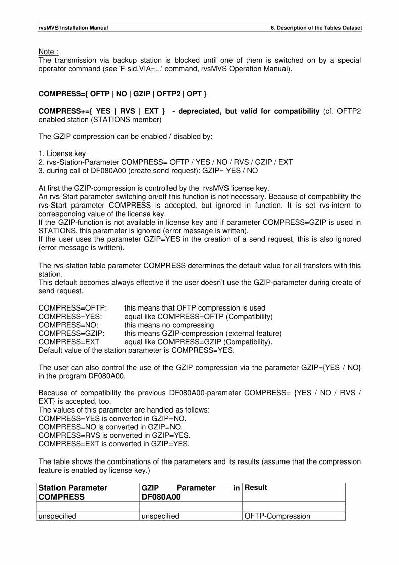
rvsMVS Installation Manual 6. Description of the Tables Dataset
Note : The transmission via backup station is blocked until one of them is switched on by a special operator command (see 'F-sid,VIA=...' command, rvsMVS Operation Manual). COMPRESS={ OFTP | NO | GZIP | OFTP2 | OPT } COMPRESS+={ YES | RVS | EXT } - depreciated, but valid for compatibility (cf. OFTP2 enabled station (STATIONS member) The GZIP compression can be enabled / disabled by: 1. License key 2. rvs-Station-Parameter COMPRESS= OFTP / YES / NO / RVS / GZIP / EXT 3. during call of DF080A00 (create send request): GZIP= YES / NO At first the GZIP-compression is controlled by the rvsMVS license key. An rvs-Start parameter switching on/off this function is not necessary. Because of compatibility the rvs-Start parameter COMPRESS is accepted, but ignored in function. It is set rvs-intern to corresponding value of the license key. If the GZIP-function is not available in license key and if parameter COMPRESS=GZIP is used in STATIONS, this parameter is ignored (error message is written). If the user uses the parameter GZIP=YES in the creation of a send request, this is also ignored (error message is written). The rvs-station table parameter COMPRESS determines the default value for all transfers with this station. This default becomes always effective if the user doesn’t use the GZIP-parameter during create of send request. COMPRESS=OFTP: this means that OFTP compression is used COMPRESS=YES: equal like COMPRESS=OFTP (Compatibility) COMPRESS=NO: this means no compressing COMPRESS=GZIP: this means GZIP-compression (external feature) COMPRESS=EXT equal like COMPRESS=GZIP (Compatibility). Default value of the station parameter is COMPRESS=YES. The user can also control the use of the GZIP compression via the parameter GZIP={YES / NO} in the program DF080A00. Because of compatibility the previous DF080A00-parameter COMPRESS= {YES / NO / RVS / EXT} is accepted, too. The values of this parameter are handled as follows: COMPRESS=YES is converted in GZIP=NO. COMPRESS=NO is converted in GZIP=NO. COMPRESS=RVS is converted in GZIP=YES. COMPRESS=EXT is converted in GZIP=YES. The table shows the combinations of the parameters and its results (assume that the compression feature is enabled by license key.)
Station Parameter COMPRESS
GZIP Parameter in DF080A00
Result
unspecified unspecified OFTP-Compression
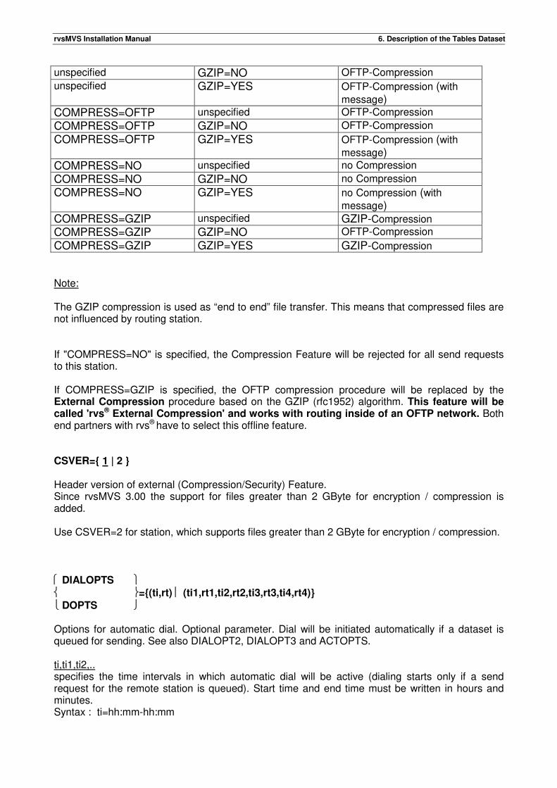
rvsMVS Installation Manual 6. Description of the Tables Dataset
unspecified GZIP=NO OFTP-Compression unspecified GZIP=YES OFTP-Compression (with
message) COMPRESS=OFTP unspecified OFTP-Compression
COMPRESS=OFTP GZIP=NO OFTP-Compression
COMPRESS=OFTP GZIP=YES OFTP-Compression (with
message) COMPRESS=NO unspecified no Compression
COMPRESS=NO GZIP=NO no Compression
COMPRESS=NO GZIP=YES no Compression (with
message) COMPRESS=GZIP unspecified GZIP-Compression COMPRESS=GZIP GZIP=NO OFTP-Compression
COMPRESS=GZIP GZIP=YES GZIP-Compression Note: The GZIP compression is used as “end to end” file transfer. This means that compressed files are not influenced by routing station. If "COMPRESS=NO" is specified, the Compression Feature will be rejected for all send requests to this station. If COMPRESS=GZIP is specified, the OFTP compression procedure will be replaced by the External Compression procedure based on the GZIP (rfc1952) algorithm. This feature will be called 'rvs® External Compression' and works with routing inside of an OFTP network. Both end partners with rvs® have to select this offline feature. CSVER={ 1 | 2 } Header version of external (Compression/Security) Feature. Since rvsMVS 3.00 the support for files greater than 2 GByte for encryption / compression is added. Use CSVER=2 for station, which supports files greater than 2 GByte for encryption / compression. DIALOPTS ={(ti,rt) (ti1,rt1,ti2,rt2,ti3,rt3,ti4,rt4)}
DOPTS Options for automatic dial. Optional parameter. Dial will be initiated automatically if a dataset is queued for sending. See also DIALOPT2, DIALOPT3 and ACTOPTS. ti,ti1,ti2,.. specifies the time intervals in which automatic dial will be active (dialing starts only if a send request for the remote station is queued). Start time and end time must be written in hours and minutes. Syntax : ti=hh:mm-hh:mm
rvsMVS Installation Manual 6. Description of the Tables Dataset
Default value is '00:00-24:00'. rt,rt1,rt2,.. specifies the retry time. The retry time is the duration the program waits for dialing again, after the last try was performed. Allowed values: 1 - 255 min. Default value is '60' minutes. The parameters must be put in brackets, separated by comma. Maximal input is four combinations of interval and retry time. Examples: DIALOPTS=(11:15-12:00,5) DOPTS=(11:15-12:00,5,14:02-17:00,10) Note: Do not specify time interval beyond midnight, separate it: Instead DOPTS=(23:00-06:00,5) use DOPTS=(23:00-24:00,5,00:00-06:00,5) DIALOPT2 ={dt (dt1,dt2,dt3,dt4)}
DOPT2 Times for mandatory automatic dial. Optional parameter. Dial will be initiated automatically if a certain time of day is reached. See also DIALOPTS, DIALOPT3 and ACTOPTS. dt,dt1,dt2,.. times of automatic dial, indicates when the remote station is to be called (dialed) one time (no retry). This function is useful for recalling datasets from a remote station at certain times of day. Up to four different times may be defined. Syntax: dt=hh:mm, Examples: DIALOPT2=14:08, DOPT2=(14:08,15:40) No default value. DIALOPT3 ={(t1-t2,r)}
DOPT3 Polling interval for automatic dial. Optional parameter. “t1-t2” denotes a time interval, "r" a retry time for this interval. Similar to the DIALOPT2 parameter, this parameter provides a polling function in view of establishing a connection. A dial request is generated automatically every "r" minutes within the specified time interval, regardless of any send requests. Syntax: t1=hh:mm, t2=hh:mm, r=value between 1 and 255 (minutes) Examples: DIALOPT3=(07:30-20:40,20)
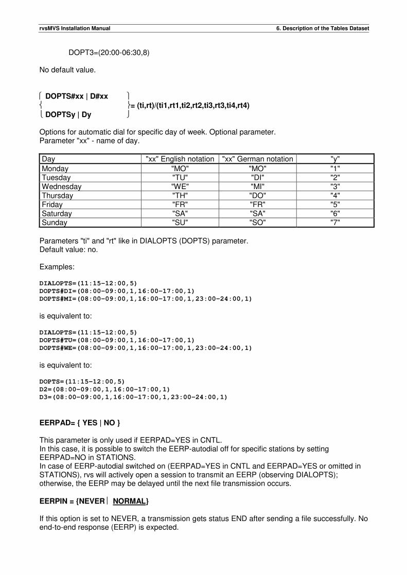
rvsMVS Installation Manual 6. Description of the Tables Dataset
DOPT3=(20:00-06:30,8) No default value.
DOPTS#xx | D#xx = (ti,rt)/(ti1,rt1,ti2,rt2,ti3,rt3,ti4,rt4)
DOPTSy | Dy Options for automatic dial for specific day of week. Optional parameter. Parameter "xx" - name of day.
Day "xx" English notation "xx" German notation "y"
Monday "MO" "MO" "1" Tuesday "TU" "DI" "2" Wednesday "WE" "MI" "3" Thursday "TH" "DO" "4" Friday "FR" "FR" "5" Saturday "SA" "SA" "6" Sunday "SU" "SO" "7"
Parameters "ti" and "rt" like in DIALOPTS (DOPTS) parameter. Default value: no. Examples: DIALOPTS=(11:15-12:00,5)
DOPTS#DI=(08:00-09:00,1,16:00-17:00,1)
DOPTS#MI=(08:00-09:00,1,16:00-17:00,1,23:00-24:00,1)
is equivalent to: DIALOPTS=(11:15-12:00,5)
DOPTS#TU=(08:00-09:00,1,16:00-17:00,1)
DOPTS#WE=(08:00-09:00,1,16:00-17:00,1,23:00-24:00,1)
is equivalent to: DOPTS=(11:15-12:00,5)
D2=(08:00-09:00,1,16:00-17:00,1)
D3=(08:00-09:00,1,16:00-17:00,1,23:00-24:00,1)
EERPAD= { YES | NO } This parameter is only used if EERPAD=YES in CNTL. In this case, it is possible to switch the EERP-autodial off for specific stations by setting EERPAD=NO in STATIONS. In case of EERP-autodial switched on (EERPAD=YES in CNTL and EERPAD=YES or omitted in STATIONS), rvs will actively open a session to transmit an EERP (observing DIALOPTS); otherwise, the EERP may be delayed until the next file transmission occurs. EERPIN = {NEVER NORMAL} If this option is set to NEVER, a transmission gets status END after sending a file successfully. No end-to-end response (EERP) is expected.
rvsMVS Installation Manual 6. Description of the Tables Dataset
If this option is set to NORMAL, an EERP is expected for a sent file.
EERPOUT = {NEVER NORMAL} If this option is set to NEVER, no end-to-end response (EERP) will be send after receiving a file successfully. If this option is set to NORMAL, an EERP will be sent after receiving a file successfully.
ISTATUS = { A[CTIVE] / I[NACTIVE] } Initial status of the station. Optional parameter. 'Inactive' stations are not able to establish a connection/session. Connection/session requests from or to an 'inactive' station will be rejected. This parameter is not valid for BTAM/BSC leased lines. NORELAY=sid Suppression of routing to the final destination 'sid'. This parameter may be used to reject receiving of files which are sent by the remote station with the destination 'sid'. Receiving of files with other destination than 'sid' will not be rejected. Remark: if 'sid' specifies the station-ID of the own (local) station, receiving of all files from the remote station with this destination will be rejected. In this case the remote station may only send files via the local station to other destinations. ODETID ='Odette-id' Odette-id = max. 25 chars.
OID Odette identification of remote station. The Odette-id must be put into quotes if it contains blanks. No default value. Mandatory parameter if you use VDA FTP 4914/1. ODETTE identifications will be defined and issued by the national automotive associations. For the Federal Republic of Germany the following address should be consulted:
Verband der Automobilindustrie e.V. (VDA) Westendstraße 61 Postfach 170563 Kennwort: VDA-AVKD 4914 60079 Frankfurt Tel.: 069-97507-283 Fax: 069-97507-300 Mail: [email protected]
Registration and distribution of ODETTE ID is not free of charge. OPTIONS ={NO RJOB RJE ROPT REPL ALL}
OPTS
rvsMVS Installation Manual 6. Description of the Tables Dataset
Authorization for remote job processing. Optional parameter. Single and combined values are allowed.
OPTS=NO: No authorization for remote job processing. OPTS=RJOB: Remote job processing is allowed. OPTS=RJE: RJE-output may be requeued. 1 OPTS=ROPT: Remote options (DISPR,DEVR,UNITR,VOLR) will be processed OPTS=REPL: Replace function is authorized. OPTS=ALL: Full authorization.
Example for combined values: OPTS=(RJOB,RJE): Remote job processing and requeuing is possible.
PHONE ='text-string' text-string = max. 16 chars. Telephone number of the final station. Optional parameter. The text-string must be put into quotes. Within the quotes all characters (blanks, commas etc.) are allowed and will not be recognized as delimiters. The maximal length of the string is 16 characters. The telephone number is only comment and can be shown on the console by the operator command 'X-sid'. No default value. SECURITY={EXT NO} The external feature security can be enabled / disabled by:
1. License key 2. rvs-Station-Parameter SECURITY= EXT / NO 3. parameter during create of send request (DF080A00): SECURITY= EXT / NO
At first the external feature security is controlled by the rvsMVS license key. An rvs-Start parameter switching on/off this function is not necessary. Because of compatibility the rvs-Start parameter SECURITY is accepted, but ignored in function. It is set rvs-intern to corresponding value of the license key. If the external feature security is not available in license key and if parameter SECURITY=EXT is used in STATIONS, this parameter is ignored (error message is written). If the user uses the parameter SECURITY=EXT during create of send request, this is also ignored (error message is written). The rvs-station table parameter SECURITY= EXT / NO determines the default value for all transfers with this station. This default becomes always effective if the user doesn’t use the SECURITY parameter during create of send request. SECURITY=EXT: this means external feature security is used. SECUTITY=NO: this means no security Default value of the station parameter: SECURITY=NO.
1 Only usable with a special software (Output Writer) distributed by VW.
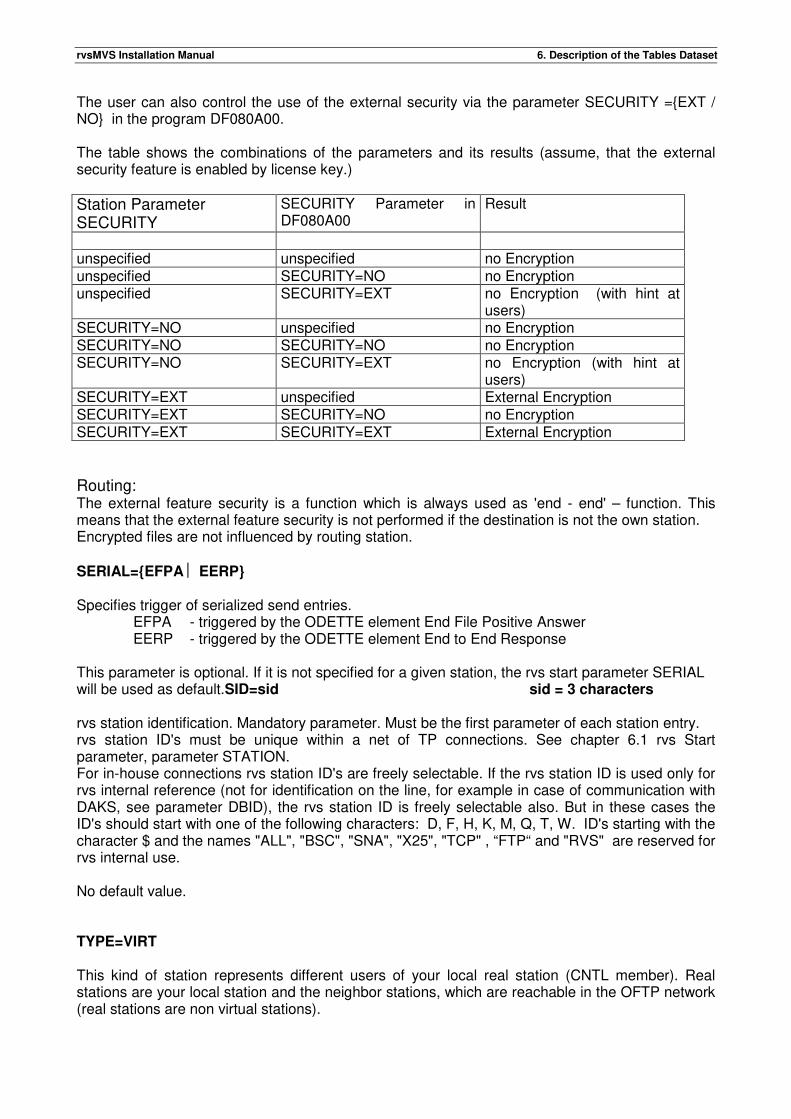
rvsMVS Installation Manual 6. Description of the Tables Dataset
The user can also control the use of the external security via the parameter SECURITY ={EXT / NO} in the program DF080A00. The table shows the combinations of the parameters and its results (assume, that the external security feature is enabled by license key.)
Station Parameter SECURITY
SECURITY Parameter in DF080A00
Result
unspecified unspecified no Encryption unspecified SECURITY=NO no Encryption unspecified SECURITY=EXT no Encryption (with hint at
users) SECURITY=NO unspecified no Encryption SECURITY=NO SECURITY=NO no Encryption SECURITY=NO SECURITY=EXT no Encryption (with hint at
users) SECURITY=EXT unspecified External Encryption SECURITY=EXT SECURITY=NO no Encryption SECURITY=EXT SECURITY=EXT External Encryption Routing: The external feature security is a function which is always used as 'end - end' – function. This means that the external feature security is not performed if the destination is not the own station. Encrypted files are not influenced by routing station. SERIAL={EFPA EERP} Specifies trigger of serialized send entries. EFPA - triggered by the ODETTE element End File Positive Answer EERP - triggered by the ODETTE element End to End Response This parameter is optional. If it is not specified for a given station, the rvs start parameter SERIAL will be used as default.SID=sid sid = 3 characters rvs station identification. Mandatory parameter. Must be the first parameter of each station entry. rvs station ID's must be unique within a net of TP connections. See chapter 6.1 rvs Start parameter, parameter STATION. For in-house connections rvs station ID's are freely selectable. If the rvs station ID is used only for rvs internal reference (not for identification on the line, for example in case of communication with DAKS, see parameter DBID), the rvs station ID is freely selectable also. But in these cases the ID's should start with one of the following characters: D, F, H, K, M, Q, T, W. ID's starting with the character $ and the names "ALL", "BSC", "SNA", "X25", "TCP" , “FTP“ and "RVS" are reserved for rvs internal use. No default value. TYPE=VIRT This kind of station represents different users of your local real station (CNTL member). Real stations are your local station and the neighbor stations, which are reachable in the OFTP network (real stations are non virtual stations).
rvsMVS Installation Manual 6. Description of the Tables Dataset
A local virtual station has one owner and possibly some users as station members. This mapping between users and a station is only possible for virtual stations. A real station doesn’t have users. When a user creates a send entry, the user table will be checked and if the userID is part of it, the founded virtual station will be used as originator. The virtual station definition consists of the parameters SID, TYPE and ODETID. Example: SID=U11, TYPE=VIRT, ODETID=’O0013003210GEDAS R11U11’
A virtual station is identified by its ODETTE-ID. This ODETTE-ID needs not to be officially requested. It must be unique in your communication area (on your system and on your partners’ systems). A local virtual station (e.g. U11) should be defined as a routed station at your partner (reachable via your local station (e.g. R11). Example: SID=VST,ADDR=’VIRTUAL STATION OF R11’, ODETID=’O0013003210GEDAS B212U11’, VIA=R11
Note: The parameters SECURITY and COMPRESS stand only for security and compression between real stations (not between virtual stations).
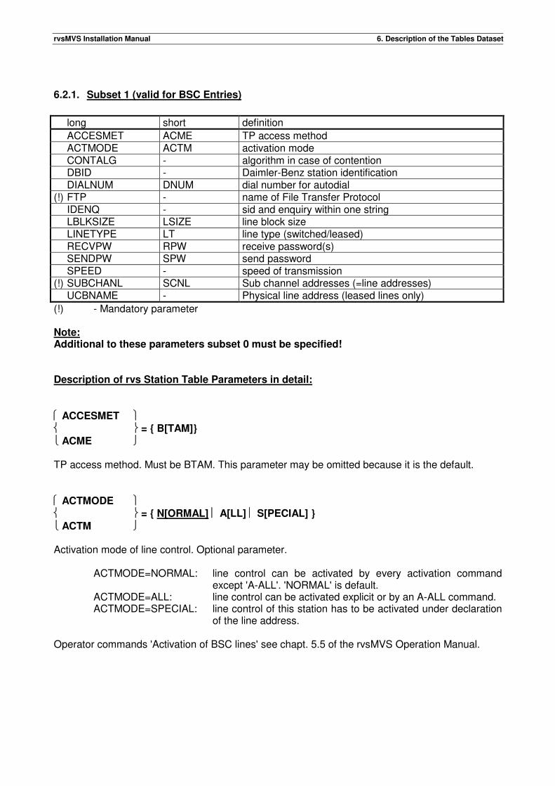
rvsMVS Installation Manual 6. Description of the Tables Dataset
6.2.1. Subset 1 (valid for BSC Entries)
long short definition
ACCESMET ACME TP access method ACTMODE ACTM activation mode CONTALG - algorithm in case of contention DBID - Daimler-Benz station identification DIALNUM DNUM dial number for autodial (!) FTP - name of File Transfer Protocol IDENQ - sid and enquiry within one string LBLKSIZE LSIZE line block size LINETYPE LT line type (switched/leased) RECVPW RPW receive password(s) SENDPW SPW send password SPEED - speed of transmission (!) SUBCHANL SCNL Sub channel addresses (=line addresses) UCBNAME - Physical line address (leased lines only)
(!) - Mandatory parameter Note: Additional to these parameters subset 0 must be specified! Description of rvs Station Table Parameters in detail: ACCESMET = { B[TAM]}
ACME TP access method. Must be BTAM. This parameter may be omitted because it is the default. ACTMODE = { N[ORMAL] A[LL] S[PECIAL] }
ACTM Activation mode of line control. Optional parameter.
ACTMODE=NORMAL: line control can be activated by every activation command except 'A-ALL'. 'NORMAL' is default.
ACTMODE=ALL: line control can be activated explicit or by an A-ALL command. ACTMODE=SPECIAL: line control of this station has to be activated under declaration
of the line address.
Operator commands 'Activation of BSC lines' see chapt. 5.5 of the rvsMVS Operation Manual.
rvsMVS Installation Manual 6. Description of the Tables Dataset
CONTALG ={ALG1 ALG2} Algorithm in case of contention situation. Optional parameter. ALG1 The first operation on the line after contention is a "write". ALG2 The first operation on the line after contention is a "read". DBID =cc cc = 1-10 characters Daimler-Benz station identification. Only necessary for communications with Daimler-Benz. Stations using DAKS (Datenaustausch-Kommunikations-System of DB) identify themselves by a (up to) 10 characters long identification number. The 'DBID' is only necessary for the identification phase - for further handling the Daimler-Benz station will be recognized within your rvs system by its rvs station-id (Parameter SID). DIALNUM =cc cc = string of max. 20 characters
DNUM Telephone number for automatic dial. Mandatory if AUTODIAL=YES. (Note: Autodial is mandatory for FTP=4914/1) If the dial interface is V.25bis, only the number to be dialed has to be coded. If the dial interface is V.25, the number to be dialed has to be extended in the following way: For "Datex-L" lines from the "Deutsche Bundespost", the characters "C3" must be added to the number. Character "C" is an indication for the dialing hardware that the end of the number to be dialed is reached. Character "3" is an indication for the control unit (37x5) that the end of the number to be passed to the dial hardware is reached. If the public telephone network is used, it may be necessary (depending on the automatic calling unit) that the telephone number is preceded by character "D" (waiting for indication from the network, that a number may be dialed, German: Freizeichen abwarten). The characters "C3" must be added to the number as well as for "Datex-L" lines. Examples: The number of Datex-L line 5361829 must be specified by "DIALNUM=5361829C3", the telephone number 05361-123456 must be specified by "DIALNUM=D05361123456C3". Remark: If the remote station has more than one line which may be used for transmissions, specification of a second (or third,...) dial number might be useful. In this case a second (third,...) stations entry should be coded. The only difference between the additional station entries for one remote station should be the different dial numbers. FTP =ftpname Name of File Transfer Protocol. Mandatory Parameter If you use switched lines the FTP parameter will substitute the old PROGPROF parameter (for leased line the PROGPROF parameter is valid further on).
rvsMVS Installation Manual 6. Description of the Tables Dataset
Following FTP's are supported by rvsMVS/BSC : 4914/0 VDA File Transfer Protocol (April '85) no blocking, no restart, no password
exchange
4914/1 VDA File Transfer Protocol (March '88) no blocking, no restart, with password exchange, autodial mandatory
rvsMVS rvs Internal Protocol of VOLKSWAGEN AG, for exclusive use with rvsMVS stations, with blocking, restart and password exchange
rvsDOS rvs Internal Protocol of VOLKSWAGEN AG, for exclusive use with rvs-DOS stations
rvsRPG rvs Internal Protocol of VOLKSWAGEN AG, for exclusive use with rvs-RPG stations
VW-FTP-B1.0 Open Protocol of VOLKSWAGEN AG, published in 'rvsMVS Interface Description', no restart, no blocking
VW-FTP-B1.1 Open Protocol of VOLKSWAGEN AG, see 'rvsMVS Interf. Descript.', with blocked transmission mode
VW-FTP-B2.1 Open Protocol of VOLKSWAGEN AG, see 'rvsMVS Interf. Descript.', with blocking and restart
VW-FTP-B3.0 Open Protocol of VOLKSWAGEN AG, see 'rvsMVS Interf. Descript.', RJE-procedure similar to 2780
IDENQ = { YES NO } The remote station may send its identification together with the BSC control character "enquiry" (X'2D') within one string. Optional. IDENQ=NO can be defined if the remote station sends its ID in a separate control record. IDENQ=YES enables rvs to receive the remote station-id and enquiry (X'2D') in one string. This is necessary for some remote stations, which must send their ID together with the enquiry. IDENQ=YES works also if the remote station sends a separate control record for the station-ID, but rvs internal tables might overflow if more than 255 station entries with IDENQ=YES on the same sub channel are defined. LBLKSIZE ={400..2000}
LSIZE Line block size for transmission. Optional parameter. Allowed are values from 400 up to 2000 bytes.
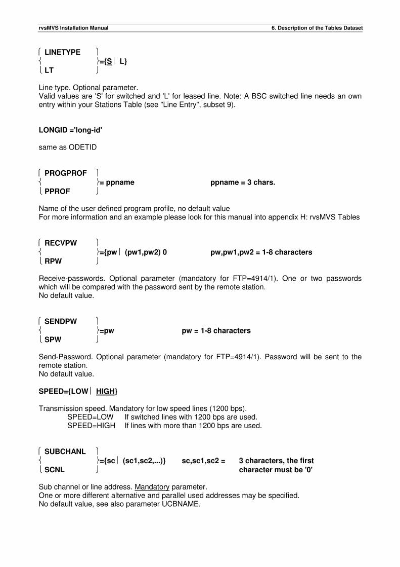
rvsMVS Installation Manual 6. Description of the Tables Dataset
LINETYPE ={S L}
LT Line type. Optional parameter. Valid values are 'S' for switched and 'L' for leased line. Note: A BSC switched line needs an own entry within your Stations Table (see "Line Entry", subset 9). LONGID ='long-id' same as ODETID
PROGPROF = ppname ppname = 3 chars.
PPROF Name of the user defined program profile, no default value For more information and an example please look for this manual into appendix H: rvsMVS Tables RECVPW ={pw (pw1,pw2) 0 pw,pw1,pw2 = 1-8 characters
RPW Receive-passwords. Optional parameter (mandatory for FTP=4914/1). One or two passwords which will be compared with the password sent by the remote station. No default value.
SENDPW =pw pw = 1-8 characters
SPW Send-Password. Optional parameter (mandatory for FTP=4914/1). Password will be sent to the remote station. No default value. SPEED={LOW HIGH} Transmission speed. Mandatory for low speed lines (1200 bps).
SPEED=LOW If switched lines with 1200 bps are used. SPEED=HIGH If lines with more than 1200 bps are used.
SUBCHANL ={sc (sc1,sc2,...)} sc,sc1,sc2 = 3 characters, the first
SCNL character must be '0' Sub channel or line address. Mandatory parameter. One or more different alternative and parallel used addresses may be specified. No default value, see also parameter UCBNAME.

rvsMVS Installation Manual 6. Description of the Tables Dataset
UCBNAME={nnn nnnn} nnn = BTAM sub channel address (3 digit UCB) nnnn = BTAM sub channel address (4 digit UCB)
This is a second way to define the sub channel or line address for leased lines. Here you are able to define three or four digit line addresses without rvs-restrictions. The value defined in parameter SUBCHANL will be used as alias name for this line or sub channel. Default value is the value defined in parameter SUBCHANL.

rvsMVS Installation Manual 6. Description of the Tables Dataset
This page will be intentionally empty.
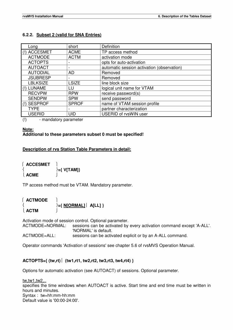
rvsMVS Installation Manual 6. Description of the Tables Dataset
6.2.2. Subset 2 (valid for SNA Entries)
Long short Definition
(!) ACCESMET ACME TP access method ACTMODE ACTM activation mode ACTOPTS - opts for auto-activation AUTOACT - automatic session activation (observation) AUTODIAL AD Removed JSUBRESP - Removed LBLKSIZE LSIZE line block size (!) LUNAME LU logical unit name for VTAM RECVPW RPW receive password(s) SENDPW SPW send password (!) SESPROF SPROF name of VTAM session profile TYPE - partner characterization USERID UID USERID of rvsWIN user
(!) - mandatory parameter Note: Additional to these parameters subset 0 must be specified! Description of rvs Station Table Parameters in detail: ACCESMET ={ V[TAM]}
ACME TP access method must be VTAM. Mandatory parameter. ACTMODE ={ N[ORMAL] A[LL] }
ACTM Activation mode of session control. Optional parameter. ACTMODE=NORMAL: sessions can be activated by every activation command except 'A-ALL'.
'NORMAL' is default. ACTMODE=ALL: sessions can be activated explicit or by an A-ALL command. Operator commands 'Activation of sessions' see chapter 5.6 of rvsMVS Operation Manual. ACTOPTS={ (tw,rt) (tw1,rt1, tw2,rt2, tw3,rt3, tw4,rt4) } Options for automatic activation (see AUTOACT) of sessions. Optional parameter. tw,tw1,tw2,.. specifies the time windows when AUTOACT is active. Start time and end time must be written in hours and minutes. Syntax : tw=hh:mm-hh:mm Default value is '00:00-24:00'.
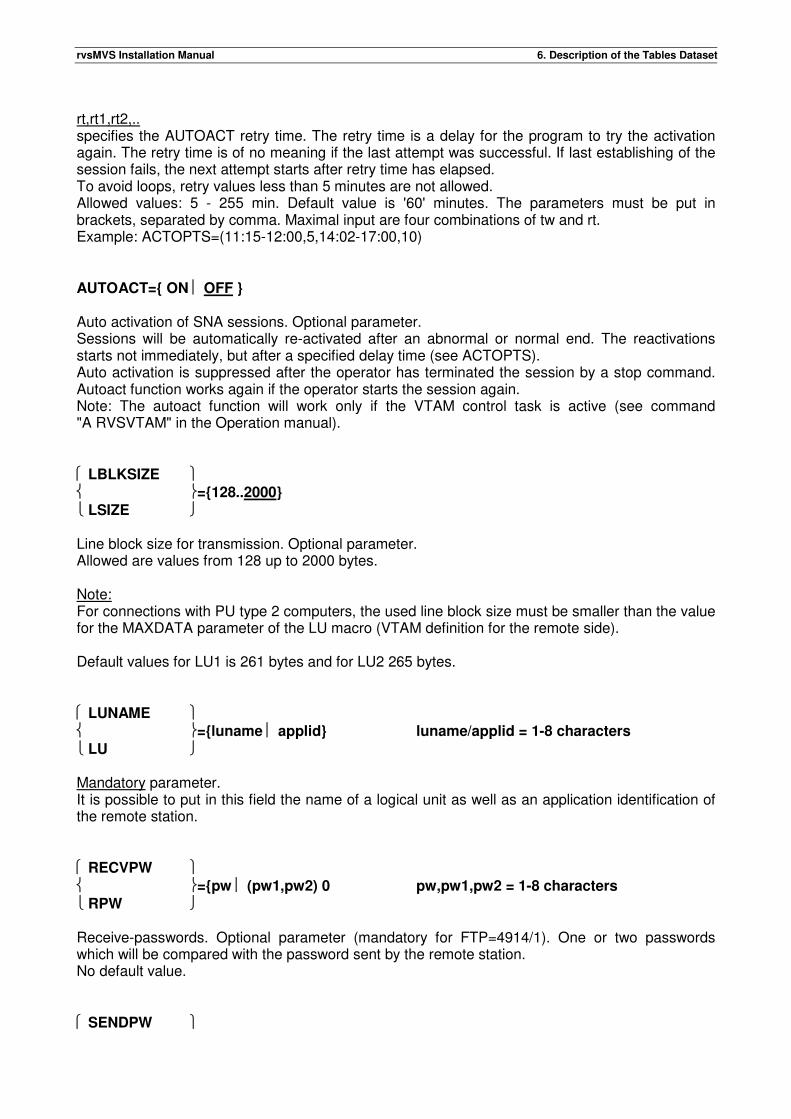
rvsMVS Installation Manual 6. Description of the Tables Dataset
rt,rt1,rt2,.. specifies the AUTOACT retry time. The retry time is a delay for the program to try the activation again. The retry time is of no meaning if the last attempt was successful. If last establishing of the session fails, the next attempt starts after retry time has elapsed. To avoid loops, retry values less than 5 minutes are not allowed. Allowed values: 5 - 255 min. Default value is '60' minutes. The parameters must be put in brackets, separated by comma. Maximal input are four combinations of tw and rt. Example: ACTOPTS=(11:15-12:00,5,14:02-17:00,10) AUTOACT={ ON OFF } Auto activation of SNA sessions. Optional parameter. Sessions will be automatically re-activated after an abnormal or normal end. The reactivations starts not immediately, but after a specified delay time (see ACTOPTS). Auto activation is suppressed after the operator has terminated the session by a stop command. Autoact function works again if the operator starts the session again. Note: The autoact function will work only if the VTAM control task is active (see command "A RVSVTAM" in the Operation manual). LBLKSIZE ={128..2000}
LSIZE Line block size for transmission. Optional parameter. Allowed are values from 128 up to 2000 bytes. Note: For connections with PU type 2 computers, the used line block size must be smaller than the value for the MAXDATA parameter of the LU macro (VTAM definition for the remote side). Default values for LU1 is 261 bytes and for LU2 265 bytes. LUNAME ={luname applid} luname/applid = 1-8 characters
LU Mandatory parameter. It is possible to put in this field the name of a logical unit as well as an application identification of the remote station. RECVPW ={pw (pw1,pw2) 0 pw,pw1,pw2 = 1-8 characters
RPW Receive-passwords. Optional parameter (mandatory for FTP=4914/1). One or two passwords which will be compared with the password sent by the remote station. No default value. SENDPW
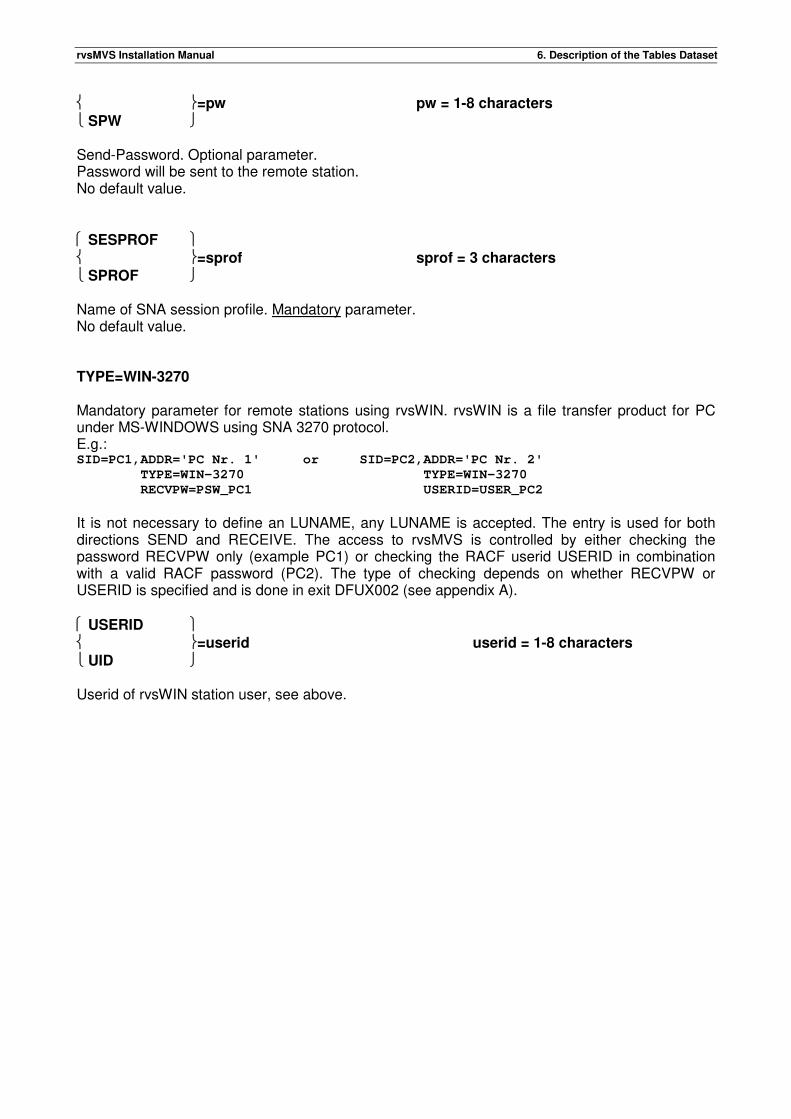
rvsMVS Installation Manual 6. Description of the Tables Dataset
=pw pw = 1-8 characters
SPW Send-Password. Optional parameter. Password will be sent to the remote station. No default value. SESPROF =sprof sprof = 3 characters
SPROF Name of SNA session profile. Mandatory parameter. No default value. TYPE=WIN-3270 Mandatory parameter for remote stations using rvsWIN. rvsWIN is a file transfer product for PC under MS-WINDOWS using SNA 3270 protocol. E.g.: SID=PC1,ADDR='PC Nr. 1' or SID=PC2,ADDR='PC Nr. 2'
TYPE=WIN-3270 TYPE=WIN-3270
RECVPW=PSW_PC1 USERID=USER_PC2
It is not necessary to define an LUNAME, any LUNAME is accepted. The entry is used for both directions SEND and RECEIVE. The access to rvsMVS is controlled by either checking the password RECVPW only (example PC1) or checking the RACF userid USERID in combination with a valid RACF password (PC2). The type of checking depends on whether RECVPW or USERID is specified and is done in exit DFUX002 (see appendix A). USERID =userid userid = 1-8 characters
UID Userid of rvsWIN station user, see above.

rvsMVS Installation Manual 6. Description of the Tables Dataset
This page will be intentionally empty.
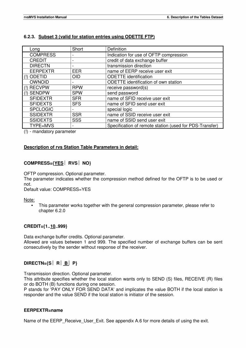
rvsMVS Installation Manual 6. Description of the Tables Dataset
6.2.3. Subset 3 (valid for station entries using ODETTE FTP)
Long Short Definition
COMPRESS - Indication for use of OFTP compression CREDIT - credit of data exchange buffer DIRECTN - transmission direction EERPEXTR EER name of EERP receive user exit (!) ODETID OID ODETTE identification OWNOID - ODETTE identification of own station (!) RECVPW RPW receive password(s) (!) SENDPW SPW send password SFIDEXTR SFR name of SFID receive user exit SFIDEXTS SFS name of SFID send user exit SPCLOGIC - special logic SSIDEXTR SSR name of SSID receive user exit SSIDEXTS SSS name of SSID send user exit TYPE=MVS - Specification of remote station (used for PDS-Transfer)
(!) - mandatory parameter Description of rvs Station Table Parameters in detail: COMPRESS={YES RVS NO} OFTP compression. Optional parameter. The parameter indicates whether the compression method defined for the OFTP is to be used or not. Default value: COMPRESS=YES Note:
• This parameter works together with the general compression parameter, please refer to chapter 6.2.0
CREDIT={1..10..999} Data exchange buffer credits. Optional parameter. Allowed are values between 1 and 999. The specified number of exchange buffers can be sent consecutively by the sender without response of the receiver. DIRECTN={S R B P} Transmission direction. Optional parameter. This attribute specifies whether the local station wants only to SEND (S) files, RECEIVE (R) files or do BOTH (B) functions during one session. P stands for 'PAY ONLY FOR SEND DATA' and implicates the value BOTH if the local station is responder and the value SEND if the local station is initiator of the session. EERPEXTR=name Name of the EERP_Receive_User_Exit. See appendix A.6 for more details of using the exit.
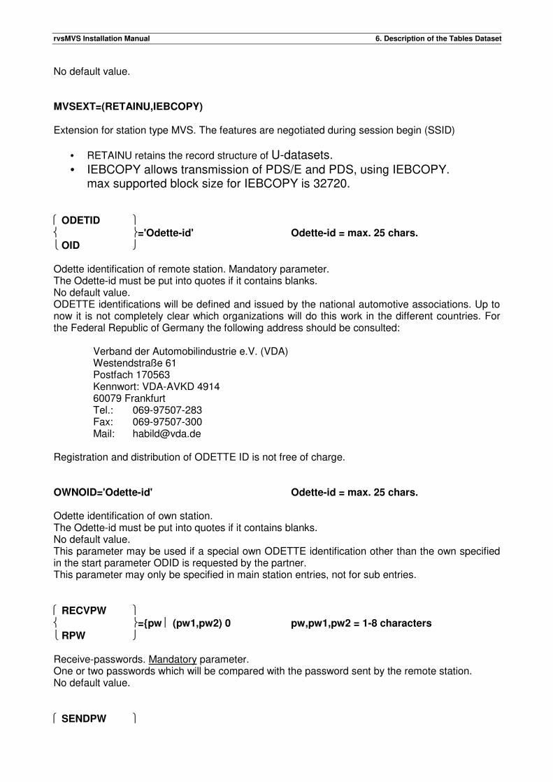
rvsMVS Installation Manual 6. Description of the Tables Dataset
No default value. MVSEXT=(RETAINU,IEBCOPY) Extension for station type MVS. The features are negotiated during session begin (SSID)
• RETAINU retains the record structure of U-datasets. • IEBCOPY allows transmission of PDS/E and PDS, using IEBCOPY.
max supported block size for IEBCOPY is 32720. ODETID ='Odette-id' Odette-id = max. 25 chars.
OID Odette identification of remote station. Mandatory parameter. The Odette-id must be put into quotes if it contains blanks. No default value. ODETTE identifications will be defined and issued by the national automotive associations. Up to now it is not completely clear which organizations will do this work in the different countries. For the Federal Republic of Germany the following address should be consulted:
Verband der Automobilindustrie e.V. (VDA) Westendstraße 61 Postfach 170563 Kennwort: VDA-AVKD 4914 60079 Frankfurt Tel.: 069-97507-283 Fax: 069-97507-300 Mail: [email protected]
Registration and distribution of ODETTE ID is not free of charge. OWNOID='Odette-id' Odette-id = max. 25 chars. Odette identification of own station. The Odette-id must be put into quotes if it contains blanks. No default value. This parameter may be used if a special own ODETTE identification other than the own specified in the start parameter ODID is requested by the partner. This parameter may only be specified in main station entries, not for sub entries. RECVPW ={pw (pw1,pw2) 0 pw,pw1,pw2 = 1-8 characters
RPW Receive-passwords. Mandatory parameter. One or two passwords which will be compared with the password sent by the remote station. No default value. SENDPW
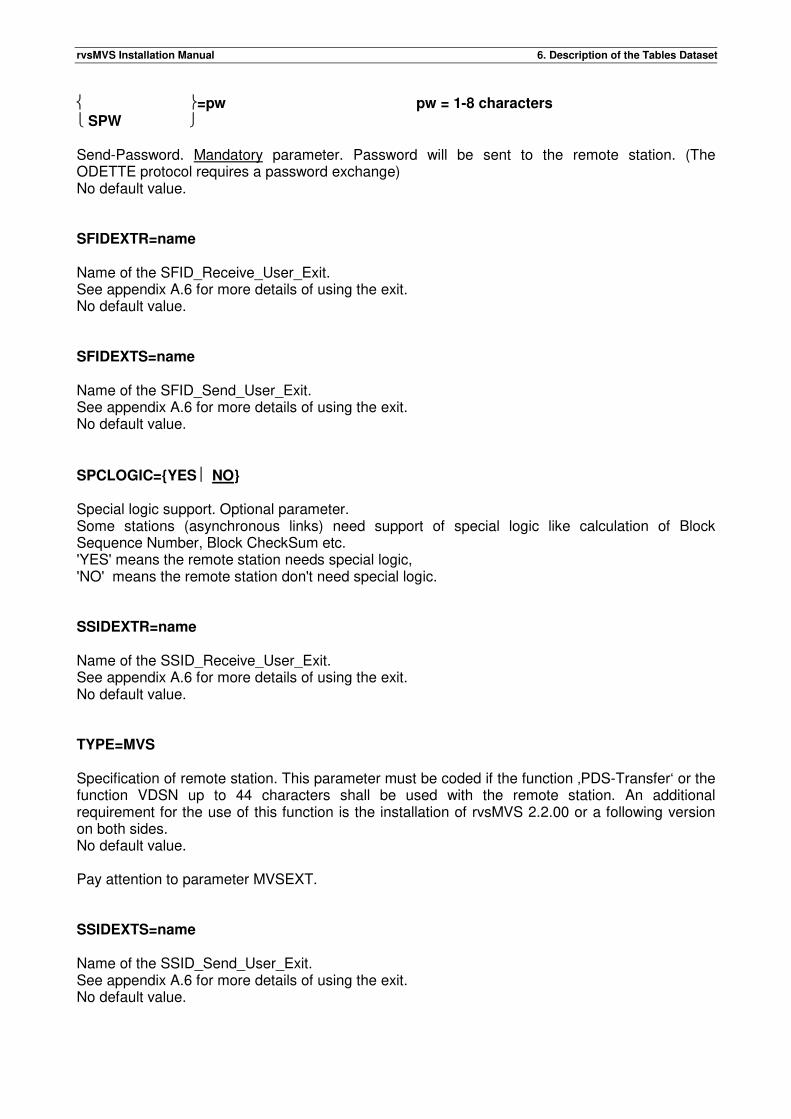
rvsMVS Installation Manual 6. Description of the Tables Dataset
=pw pw = 1-8 characters
SPW Send-Password. Mandatory parameter. Password will be sent to the remote station. (The ODETTE protocol requires a password exchange) No default value. SFIDEXTR=name Name of the SFID_Receive_User_Exit. See appendix A.6 for more details of using the exit. No default value. SFIDEXTS=name Name of the SFID_Send_User_Exit. See appendix A.6 for more details of using the exit. No default value. SPCLOGIC={YES NO} Special logic support. Optional parameter. Some stations (asynchronous links) need support of special logic like calculation of Block Sequence Number, Block CheckSum etc. 'YES' means the remote station needs special logic, 'NO' means the remote station don't need special logic. SSIDEXTR=name Name of the SSID_Receive_User_Exit. See appendix A.6 for more details of using the exit. No default value. TYPE=MVS Specification of remote station. This parameter must be coded if the function ‚PDS-Transfer‘ or the function VDSN up to 44 characters shall be used with the remote station. An additional requirement for the use of this function is the installation of rvsMVS 2.2.00 or a following version on both sides. No default value. Pay attention to parameter MVSEXT. SSIDEXTS=name Name of the SSID_Send_User_Exit. See appendix A.6 for more details of using the exit. No default value.

rvsMVS Installation Manual 6. Description of the Tables Dataset
This page will be intentionally empty.
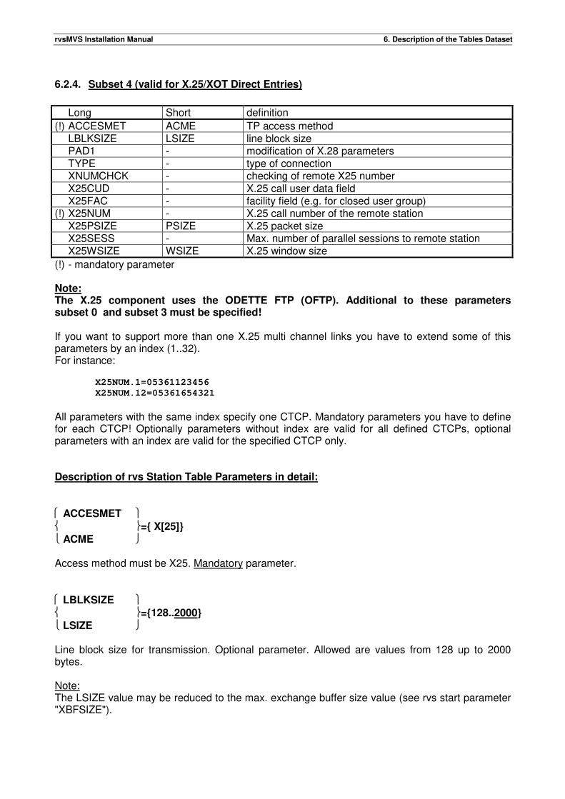
rvsMVS Installation Manual 6. Description of the Tables Dataset
6.2.4. Subset 4 (valid for X.25/XOT Direct Entries)
Long Short definition
(!) ACCESMET ACME TP access method LBLKSIZE LSIZE line block size PAD1 - modification of X.28 parameters TYPE - type of connection XNUMCHCK - checking of remote X25 number X25CUD - X.25 call user data field X25FAC - facility field (e.g. for closed user group) (!) X25NUM - X.25 call number of the remote station X25PSIZE PSIZE X.25 packet size X25SESS - Max. number of parallel sessions to remote station X25WSIZE WSIZE X.25 window size
(!) - mandatory parameter Note: The X.25 component uses the ODETTE FTP (OFTP). Additional to these parameters subset 0 and subset 3 must be specified! If you want to support more than one X.25 multi channel links you have to extend some of this parameters by an index (1..32). For instance:
X25NUM.1=05361123456
X25NUM.12=05361654321
All parameters with the same index specify one CTCP. Mandatory parameters you have to define for each CTCP! Optionally parameters without index are valid for all defined CTCPs, optional parameters with an index are valid for the specified CTCP only. Description of rvs Station Table Parameters in detail: ACCESMET ={ X[25]}
ACME Access method must be X25. Mandatory parameter. LBLKSIZE ={128..2000}
LSIZE Line block size for transmission. Optional parameter. Allowed are values from 128 up to 2000 bytes. Note: The LSIZE value may be reduced to the max. exchange buffer size value (see rvs start parameter "XBFSIZE").
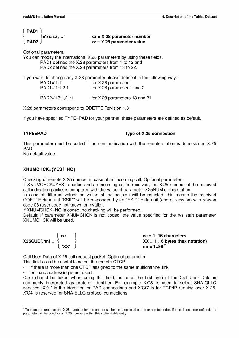
rvsMVS Installation Manual 6. Description of the Tables Dataset
PAD1 ='xx:zz ,... ' xx = X.28 parameter number
PAD2 zz = X.28 parameter value Optional parameters. You can modify the international X.28 parameters by using these fields.
PAD1 defines the X.28 parameters from 1 to 12 and PAD2 defines the X.28 parameters from 13 to 22.
If you want to change any X.28 parameter please define it in the following way:
PAD1='1:1' for X.28 parameter 1 PAD1='1:1,2:1' for X.28 parameter 1 and 2 ... PAD2='13:1,21:1' for X.28 parameters 13 and 21
X.28 parameters correspond to ODETTE Revision 1.3 If you have specified TYPE=PAD for your partner, these parameters are defined as default. TYPE=PAD type of X.25 connection This parameter must be coded if the communication with the remote station is done via an X.25 PAD. No default value. XNUMCHCK={YES NO} Checking of remote X.25 number in case of an incoming call. Optional parameter. If XNUMCHCK=YES is coded and an incoming call is received, the X.25 number of the received call indication packet is compared with the value of parameter X25NUM of this station. In case of different values activation of the session will be rejected, this means the received ODETTE data unit "SSID" will be responded by an "ESID" data unit (end of session) with reason code 03 (user code not known or invalid). If XNUMCHCK=NO is coded, no checking will be performed. Default: If parameter XNUMCHCK is not coded, the value specified for the rvs start parameter XNUMCHCK will be used.
cc cc = 1..16 characters
X25CUD[.nn] = XX = 1..16 bytes (hex notation)
'XX' nn = 1..99 2 Call User Data of X.25 call request packet. Optional parameter. This field could be useful to select the remote CTCP • if there is more than one CTCP assigned to the same multichannel link • or if sub addressing is not used. Care should be taken when using this field, because the first byte of the Call User Data is commonly interpreted as protocol identifier. For example X'C3' is used to select SNA-QLLC services, X'01' is the identifier for PAD connections and X'CC' is for TCP/IP running over X.25. X'C4' is reserved for SNA-ELLC protocol connections.
2 To support more than one X.25 numbers for one partner station nn specifies the partner number index. If there is no index defined, the parameter will be used for all X.25 numbers within this station table entry.
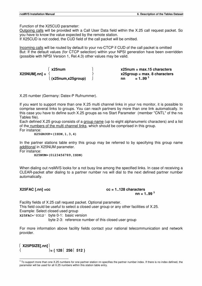
rvsMVS Installation Manual 6. Description of the Tables Dataset
Function of the X25CUD parameter: Outgoing calls will be provided with a Call User Data field within the X.25 call request packet. So you have to know the value expected by the remote station. If X25CUD is not coded, the CUD field of the call packet will be omitted. Incoming calls will be routed by default to your rvs-CTCP if CUD of the call packet is omitted But: If the default values (for CTCP selection) within your NPSI generation have been overridden (possible with NPSI Version 1, Rel.4.3) other values may be valid.
x25num x25num = max.15 characters
X25NUM[.nn] = x25group = max. 8 characters
(x25num,x25group) nn = 1..99 3
X.25 number (Germany: Datex-P Rufnummer). If you want to support more than one X.25 multi channel links in your rvs monitor, it is possible to comprise several links to groups. You can reach partners by more than one link automatically. In this case you have to define such X.25 groups as rvs Start Parameter (member "CNTL" of the rvs Tables file). Each defined X.25 group consists of a group name (up to eight alphanumeric characters) and a list of the numbers of the multi channel links, which should be comprised in this group. For instance:
X25GROUP=(ISDN,1,3,4)
In the partner stations table entry this group may be referred to by specifying this group name additional in X25NUM parameter. For instance:
X25NUM=(0123456789,ISDN)
When dialing out rvsMVS looks for a not busy line among the specified links. In case of receiving a CLEAR-packet after dialing to a partner number rvs will dial to the next defined partner number automatically. X25FAC [.nn] =cc cc = 1..128 characters
nn = 1..99 3 Facility fields of X.25 call request packet. Optional parameter. This field could be useful to select a closed user group or any other facilities of X.25. Example: Select closed used group X25FAC='0312' byte 0-1: basic version
byte 2-3: reference number of this closed user group For more information above facility fields contact your national telecommunication and network provider. X25PSIZE[.nn] = { 128 256 512 }
3 To support more than one X.25 numbers for one partner station nn specifies the partner number index. If there is no index defined, the parameter will be used for all X.25 numbers within this station table entry.
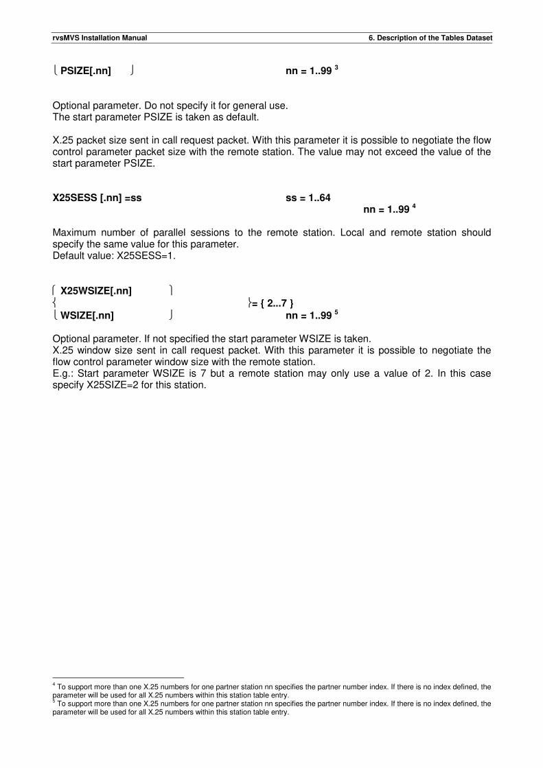
rvsMVS Installation Manual 6. Description of the Tables Dataset
PSIZE[.nn] nn = 1..99 3
Optional parameter. Do not specify it for general use. The start parameter PSIZE is taken as default. X.25 packet size sent in call request packet. With this parameter it is possible to negotiate the flow control parameter packet size with the remote station. The value may not exceed the value of the start parameter PSIZE. X25SESS [.nn] =ss ss = 1..64
nn = 1..99 4 Maximum number of parallel sessions to the remote station. Local and remote station should specify the same value for this parameter. Default value: X25SESS=1. X25WSIZE[.nn] = { 2...7 }
WSIZE[.nn] nn = 1..99 5
Optional parameter. If not specified the start parameter WSIZE is taken. X.25 window size sent in call request packet. With this parameter it is possible to negotiate the flow control parameter window size with the remote station. E.g.: Start parameter WSIZE is 7 but a remote station may only use a value of 2. In this case specify X25SIZE=2 for this station.
4 To support more than one X.25 numbers for one partner station nn specifies the partner number index. If there is no index defined, the parameter will be used for all X.25 numbers within this station table entry. 5 To support more than one X.25 numbers for one partner station nn specifies the partner number index. If there is no index defined, the parameter will be used for all X.25 numbers within this station table entry.
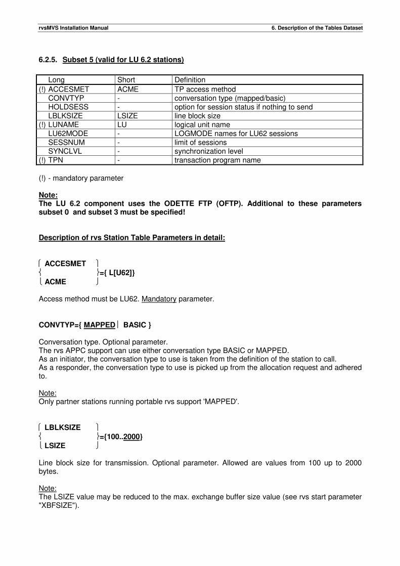
rvsMVS Installation Manual 6. Description of the Tables Dataset
6.2.5. Subset 5 (valid for LU 6.2 stations)
Long Short Definition
(!) ACCESMET ACME TP access method CONVTYP - conversation type (mapped/basic) HOLDSESS - option for session status if nothing to send LBLKSIZE LSIZE line block size (!) LUNAME LU logical unit name LU62MODE - LOGMODE names for LU62 sessions SESSNUM - limit of sessions SYNCLVL - synchronization level (!) TPN - transaction program name
(!) - mandatory parameter Note: The LU 6.2 component uses the ODETTE FTP (OFTP). Additional to these parameters subset 0 and subset 3 must be specified! Description of rvs Station Table Parameters in detail: ACCESMET ={ L[U62]}
ACME Access method must be LU62. Mandatory parameter. CONVTYP={ MAPPED BASIC } Conversation type. Optional parameter. The rvs APPC support can use either conversation type BASIC or MAPPED. As an initiator, the conversation type to use is taken from the definition of the station to call. As a responder, the conversation type to use is picked up from the allocation request and adhered to. Note: Only partner stations running portable rvs support 'MAPPED'. LBLKSIZE ={100..2000}
LSIZE Line block size for transmission. Optional parameter. Allowed are values from 100 up to 2000 bytes. Note: The LSIZE value may be reduced to the max. exchange buffer size value (see rvs start parameter "XBFSIZE").
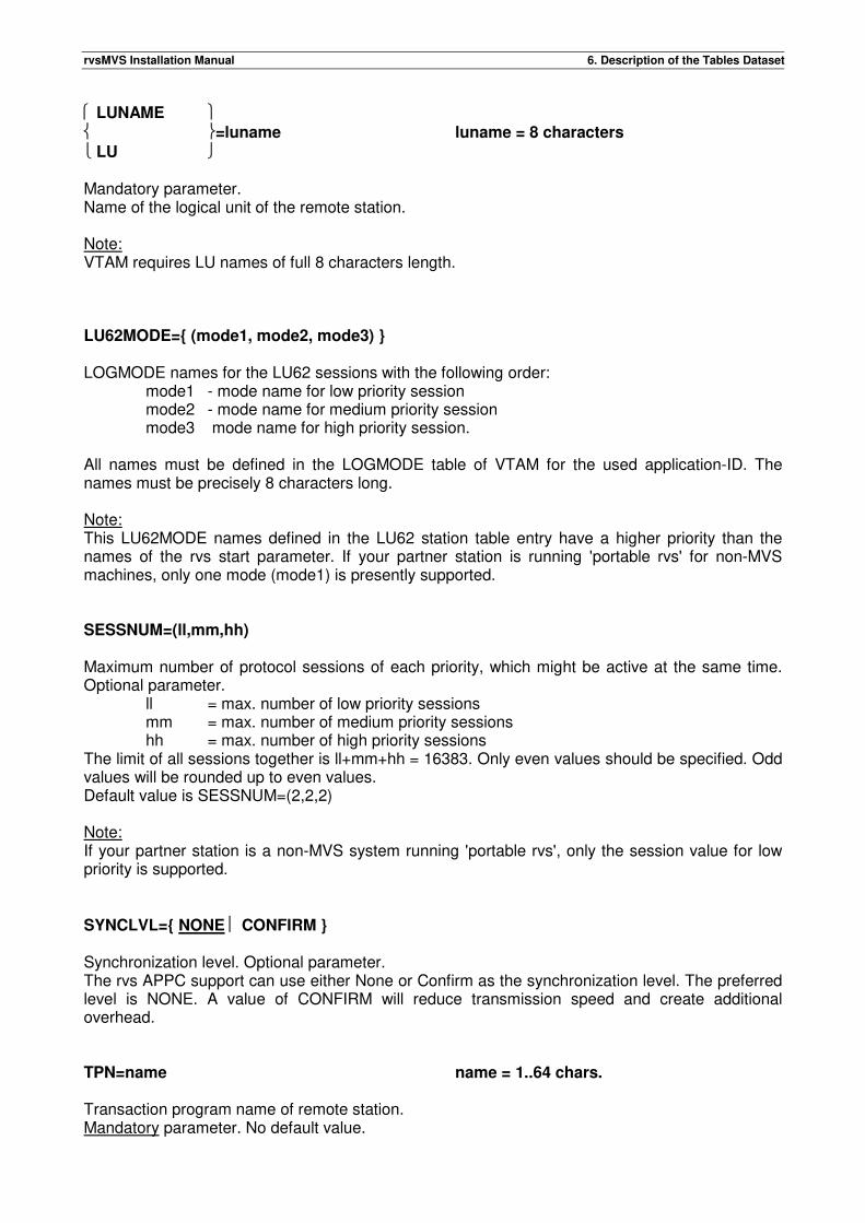
rvsMVS Installation Manual 6. Description of the Tables Dataset
LUNAME =luname luname = 8 characters
LU Mandatory parameter. Name of the logical unit of the remote station. Note: VTAM requires LU names of full 8 characters length. LU62MODE={ (mode1, mode2, mode3) } LOGMODE names for the LU62 sessions with the following order:
mode1 - mode name for low priority session mode2 - mode name for medium priority session mode3 mode name for high priority session.
All names must be defined in the LOGMODE table of VTAM for the used application-ID. The names must be precisely 8 characters long. Note: This LU62MODE names defined in the LU62 station table entry have a higher priority than the names of the rvs start parameter. If your partner station is running 'portable rvs' for non-MVS machines, only one mode (mode1) is presently supported. SESSNUM=(ll,mm,hh) Maximum number of protocol sessions of each priority, which might be active at the same time. Optional parameter.
ll = max. number of low priority sessions mm = max. number of medium priority sessions hh = max. number of high priority sessions
The limit of all sessions together is ll+mm+hh = 16383. Only even values should be specified. Odd values will be rounded up to even values. Default value is SESSNUM=(2,2,2) Note: If your partner station is a non-MVS system running 'portable rvs', only the session value for low priority is supported. SYNCLVL={ NONE CONFIRM } Synchronization level. Optional parameter. The rvs APPC support can use either None or Confirm as the synchronization level. The preferred level is NONE. A value of CONFIRM will reduce transmission speed and create additional overhead. TPN=name name = 1..64 chars. Transaction program name of remote station. Mandatory parameter. No default value.

rvsMVS Installation Manual 6. Description of the Tables Dataset
TPN indicates the name of the program to which a conversation is requested. Important for your remote partner : To select the service of the Odette File Transfer Protocol of rvsMVS he has to use the following TP-name value : 'RVSOFTP' If your partner station is a non-MVS system running 'portable rvs' the TP-name is 'RVSRCV'.

rvsMVS Installation Manual 6. Description of the Tables Dataset
This page will be intentionally empty.
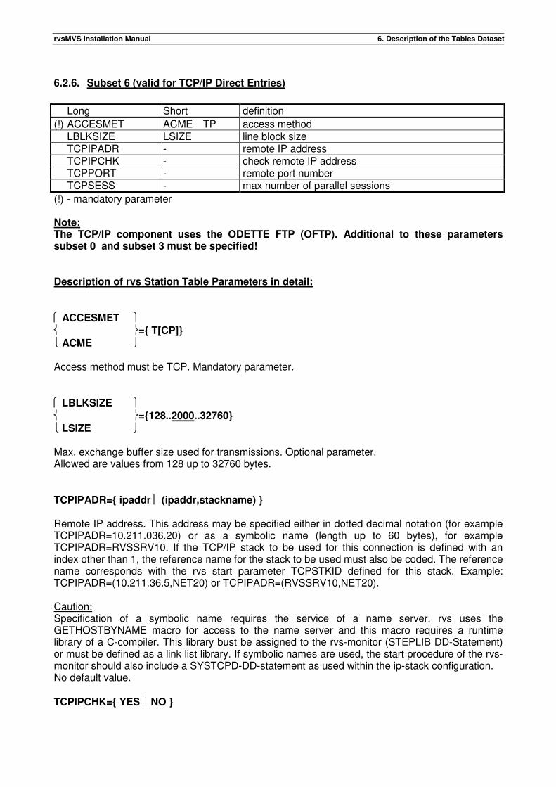
rvsMVS Installation Manual 6. Description of the Tables Dataset
6.2.6. Subset 6 (valid for TCP/IP Direct Entries)
Long Short definition
(!) ACCESMET ACME TP access method LBLKSIZE LSIZE line block size TCPIPADR - remote IP address TCPIPCHK - check remote IP address TCPPORT - remote port number TCPSESS - max number of parallel sessions
(!) - mandatory parameter Note: The TCP/IP component uses the ODETTE FTP (OFTP). Additional to these parameters subset 0 and subset 3 must be specified! Description of rvs Station Table Parameters in detail: ACCESMET ={ T[CP]}
ACME Access method must be TCP. Mandatory parameter. LBLKSIZE ={128..2000..32760}
LSIZE Max. exchange buffer size used for transmissions. Optional parameter. Allowed are values from 128 up to 32760 bytes. TCPIPADR={ ipaddr (ipaddr,stackname) } Remote IP address. This address may be specified either in dotted decimal notation (for example TCPIPADR=10.211.036.20) or as a symbolic name (length up to 60 bytes), for example TCPIPADR=RVSSRV10. If the TCP/IP stack to be used for this connection is defined with an index other than 1, the reference name for the stack to be used must also be coded. The reference name corresponds with the rvs start parameter TCPSTKID defined for this stack. Example: TCPIPADR=(10.211.36.5,NET20) or TCPIPADR=(RVSSRV10,NET20). Caution: Specification of a symbolic name requires the service of a name server. rvs uses the GETHOSTBYNAME macro for access to the name server and this macro requires a runtime library of a C-compiler. This library bust be assigned to the rvs-monitor (STEPLIB DD-Statement) or must be defined as a link list library. If symbolic names are used, the start procedure of the rvs-monitor should also include a SYSTCPD-DD-statement as used within the ip-stack configuration. No default value. TCPIPCHK={ YES NO }
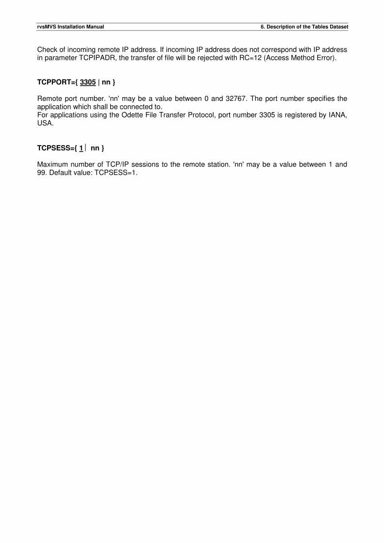
rvsMVS Installation Manual 6. Description of the Tables Dataset
Check of incoming remote IP address. If incoming IP address does not correspond with IP address
in parameter TCPIPADR, the transfer of file will be rejected with RC=12 (Access Method Error). TCPPORT={ 3305 | nn } Remote port number. 'nn' may be a value between 0 and 32767. The port number specifies the application which shall be connected to. For applications using the Odette File Transfer Protocol, port number 3305 is registered by IANA, USA. TCPSESS={ 1 nn } Maximum number of TCP/IP sessions to the remote station. 'nn' may be a value between 1 and 99. Default value: TCPSESS=1.
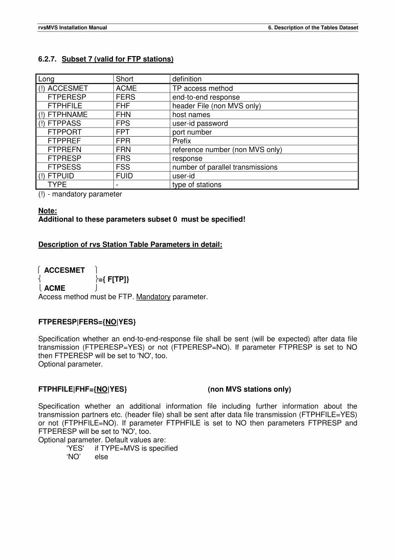
rvsMVS Installation Manual 6. Description of the Tables Dataset
6.2.7. Subset 7 (valid for FTP stations)
Long Short definition
(!) ACCESMET ACME TP access method FTPERESP FERS end-to-end response FTPHFILE FHF header File (non MVS only) (!) FTPHNAME FHN host names (!) FTPPASS FPS user-id password FTPPORT FPT port number FTPPREF FPR Prefix FTPREFN FRN reference number (non MVS only) FTPRESP FRS response FTPSESS FSS number of parallel transmissions (!) FTPUID FUID user-id TYPE - type of stations
(!) - mandatory parameter Note: Additional to these parameters subset 0 must be specified! Description of rvs Station Table Parameters in detail: ACCESMET ={ F[TP]}
ACME Access method must be FTP. Mandatory parameter. FTPERESP|FERS={NO|YES} Specification whether an end-to-end-response file shall be sent (will be expected) after data file transmission (FTPERESP=YES) or not (FTPERESP=NO). If parameter FTPRESP is set to NO then FTPERESP will be set to 'NO', too. Optional parameter. FTPHFILE|FHF={NO|YES} (non MVS stations only) Specification whether an additional information file including further information about the transmission partners etc. (header file) shall be sent after data file transmission (FTPHFILE=YES) or not (FTPHFILE=NO). If parameter FTPHFILE is set to NO then parameters FTPRESP and FTPERESP will be set to 'NO', too. Optional parameter. Default values are: 'YES' if TYPE=MVS is specified ‘NO’ else
rvsMVS Installation Manual 6. Description of the Tables Dataset
FTPHNAME|FHN=name (name: 1-64 characters) Remote IP address. This address may be specified either in dotted decimal notation (for example FTPHNAME=10.211.036.20) or as a symbolic name (length up to 24 bytes), for example FTPHNAME=VWRVSB No default value. FTPPASS|FPS=text (text: 1-20 characters) FTP password for the partner station. No default value. FTPPORT|FPT=( 21 | nnnnn | X'xxxx' } (port: 1-65534) Remote port number. 'nn' may be a value between 0 and 65534 (hexadecimal X'FFFE'). The port number specifies the application which shall be connected to. FTPPREF|FPR=name (name: 1-18 characters) Specifies the prefix which should be used for construction of dataset names for additional control file. Optional parameter The names of such protocol files look as follows: prefix.FTPxx.sidoriginsidFTPserver.siddestination.refnumber
prefix = value of FTPPREF parameter FTPxx = constant sidorigin = origin station id sidFTP server = sid of next FTP station siddestination = destination station id refnumber = an unique number/stamp to avoid conflicts with duplicate control file
names The prefix has to correspond to MVS DSName conventions(on MVS hosts), PC file name conventions (on PC stations) or UNIX file name conventions (on UNIX like stations). Examples of control file name (information file): 1.MVS - FTPPREF=MVSPREF, - origin station: AAA - next FTP station: BBB - destination station: CCC control file name: MVSPREF.FTPHD.AAABBB.CCC.F000123 2. PC - FTPPREF=ftprvs/ - origin station: XXX - next FTP server station: YYY
rvsMVS Installation Manual 6. Description of the Tables Dataset
- destination station: YYY control file name: ftprvs/ftphd.xxxyyy.yyy.f000123 FTPREFN|FRN={NO|YES} (non MVS stations only) Specifies whether the DSN of the file which should be transmitted will be added by a stamp. Defaults: 'NO' non-MVS stations ‘YES’ MVS stations FTPRESP|FRS={NO|YES} Specifies whether a response file will be expected (shall be sent) after data file transmission (FTPRESP=YES) or not (FTPRESP=NO). If parameter FTPRESP is set to NO then FTPERESP will be set to 'NO', too. FTPSESS|FSS={ 1 | nn } (nn: 1-16) Specifies the max. number of parallel transmissions to the same FTP partner station. Allowed are values between 1 and 16. FTPUID|FUID=user-id (user-id: 1-64 characters) FTP login name of the partner station. No default value. TYPE ={ MVS | SINIX | PC } This parameter specifies the computer type of the partner stations. The FTP component of rvsMVS supports three types of stations: - MVS - SINIX - PC Optional parameter.

rvsMVS Installation Manual 6. Description of the Tables Dataset
This page will be intentionally empty.
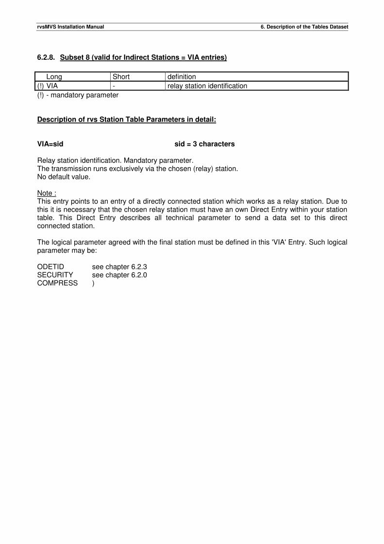
rvsMVS Installation Manual 6. Description of the Tables Dataset
6.2.8. Subset 8 (valid for Indirect Stations = VIA entries)
Long Short definition
(!) VIA - relay station identification
(!) - mandatory parameter Description of rvs Station Table Parameters in detail: VIA=sid sid = 3 characters Relay station identification. Mandatory parameter. The transmission runs exclusively via the chosen (relay) station. No default value. Note : This entry points to an entry of a directly connected station which works as a relay station. Due to this it is necessary that the chosen relay station must have an own Direct Entry within your station table. This Direct Entry describes all technical parameter to send a data set to this direct connected station. The logical parameter agreed with the final station must be defined in this 'VIA' Entry. Such logical parameter may be: ODETID see chapter 6.2.3 SECURITY see chapter 6.2.0 COMPRESS )

rvsMVS Installation Manual 6. Description of the Tables Dataset
This page will be intentionally empty.
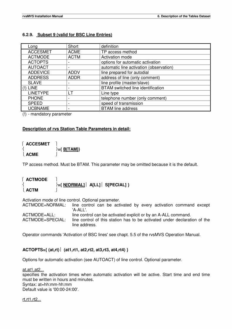
rvsMVS Installation Manual 6. Description of the Tables Dataset
6.2.9. Subset 9 (valid for BSC Line Entries)
Long Short definition
ACCESMET ACME TP access method ACTMODE ACTM Activation mode ACTOPTS - options for automatic activation AUTOACT - automatic line activation (observation) ADDEVICE ADDV line prepared for autodial ADDRESS ADDR address of line (only comment) SLAVE - line profile (master/slave) (!) LINE - BTAM switched line identification LINETYPE LT Line type PHONE - telephone number (only comment) SPEED - speed of transmission UCBNAME - BTAM line address
(!) - mandatory parameter Description of rvs Station Table Parameters in detail: ACCESMET ={ B[TAM]}
ACME TP access method. Must be BTAM. This parameter may be omitted because it is the default. ACTMODE ={ N[ORMAL] A[LL] S[PECIAL] }
ACTM Activation mode of line control. Optional parameter. ACTMODE=NORMAL: line control can be activated by every activation command except
'A-ALL'. ACTMODE=ALL: line control can be activated explicit or by an A-ALL command. ACTMODE=SPECIAL: line control of this station has to be activated under declaration of the
line address. Operator commands 'Activation of BSC lines' see chapt. 5.5 of the rvsMVS Operation Manual. ACTOPTS={ (at,rt) (at1,rt1, at2,rt2, at3,rt3, at4,rt4) } Options for automatic activation (see AUTOACT) of line control. Optional parameter. at,at1,at2,.. specifies the activation times when automatic activation will be active. Start time and end time must be written in hours and minutes. Syntax: at=hh:mm-hh:mm Default value is '00:00-24:00'. rt,rt1,rt2,..
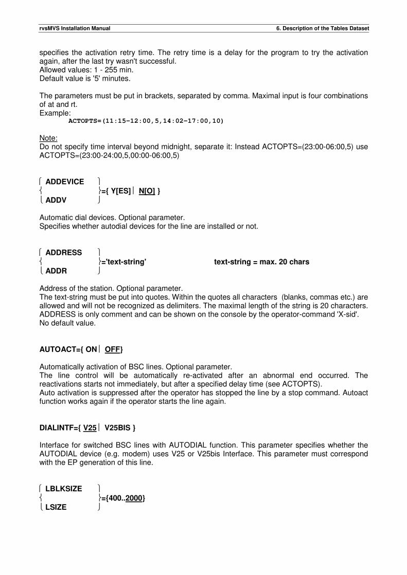
rvsMVS Installation Manual 6. Description of the Tables Dataset
specifies the activation retry time. The retry time is a delay for the program to try the activation again, after the last try wasn't successful. Allowed values: 1 - 255 min. Default value is '5' minutes. The parameters must be put in brackets, separated by comma. Maximal input is four combinations of at and rt. Example: ACTOPTS=(11:15-12:00,5,14:02-17:00,10)
Note: Do not specify time interval beyond midnight, separate it: Instead ACTOPTS=(23:00-06:00,5) use ACTOPTS=(23:00-24:00,5,00:00-06:00,5) ADDEVICE ={ Y[ES] N[O] }
ADDV Automatic dial devices. Optional parameter. Specifies whether autodial devices for the line are installed or not. ADDRESS ='text-string' text-string = max. 20 chars
ADDR Address of the station. Optional parameter. The text-string must be put into quotes. Within the quotes all characters (blanks, commas etc.) are allowed and will not be recognized as delimiters. The maximal length of the string is 20 characters. ADDRESS is only comment and can be shown on the console by the operator-command 'X-sid'. No default value. AUTOACT={ ON OFF} Automatically activation of BSC lines. Optional parameter. The line control will be automatically re-activated after an abnormal end occurred. The reactivations starts not immediately, but after a specified delay time (see ACTOPTS). Auto activation is suppressed after the operator has stopped the line by a stop command. Autoact function works again if the operator starts the line again. DIALINTF={ V25 V25BIS } Interface for switched BSC lines with AUTODIAL function. This parameter specifies whether the AUTODIAL device (e.g. modem) uses V25 or V25bis Interface. This parameter must correspond with the EP generation of this line. LBLKSIZE ={400..2000}
LSIZE
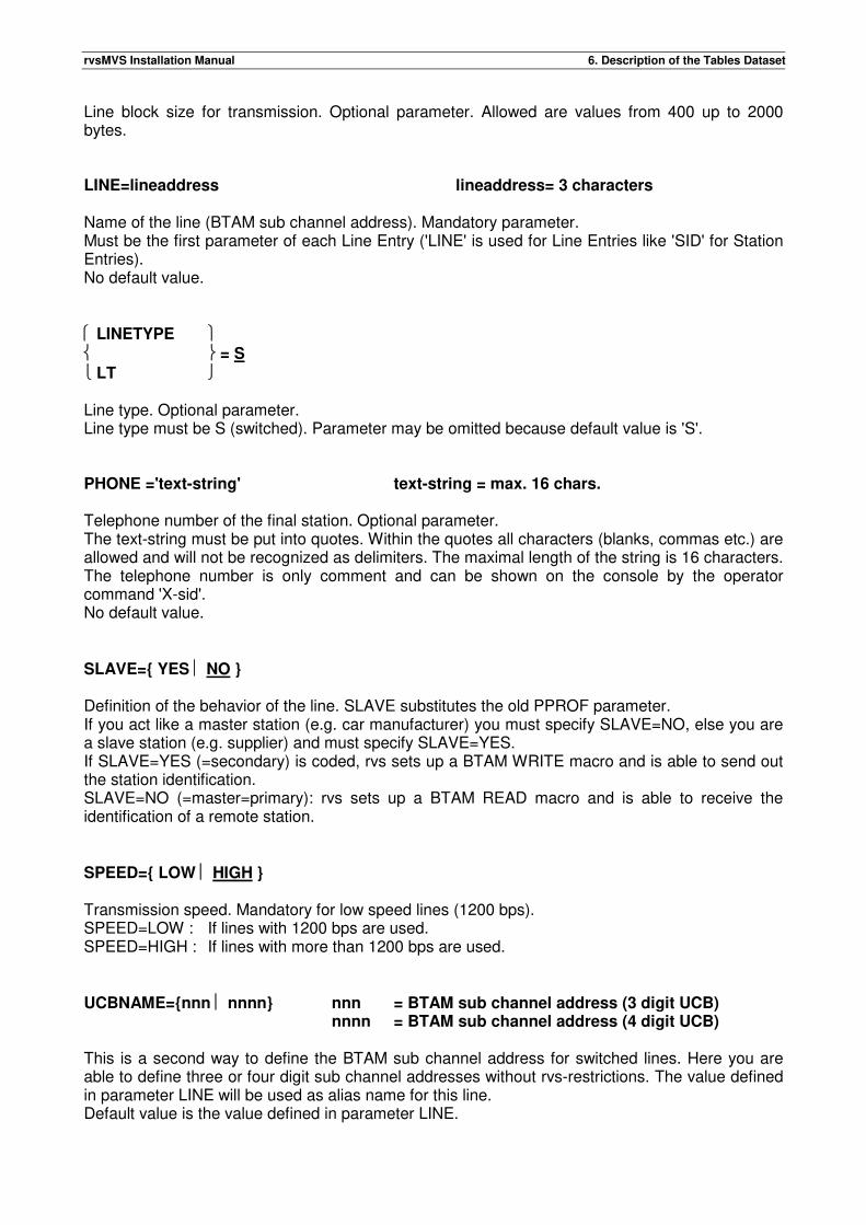
rvsMVS Installation Manual 6. Description of the Tables Dataset
Line block size for transmission. Optional parameter. Allowed are values from 400 up to 2000 bytes. LINE=lineaddress lineaddress= 3 characters Name of the line (BTAM sub channel address). Mandatory parameter. Must be the first parameter of each Line Entry ('LINE' is used for Line Entries like 'SID' for Station Entries). No default value. LINETYPE = S
LT Line type. Optional parameter. Line type must be S (switched). Parameter may be omitted because default value is 'S'. PHONE ='text-string' text-string = max. 16 chars. Telephone number of the final station. Optional parameter. The text-string must be put into quotes. Within the quotes all characters (blanks, commas etc.) are allowed and will not be recognized as delimiters. The maximal length of the string is 16 characters. The telephone number is only comment and can be shown on the console by the operator command 'X-sid'. No default value. SLAVE={ YES NO } Definition of the behavior of the line. SLAVE substitutes the old PPROF parameter. If you act like a master station (e.g. car manufacturer) you must specify SLAVE=NO, else you are a slave station (e.g. supplier) and must specify SLAVE=YES. If SLAVE=YES (=secondary) is coded, rvs sets up a BTAM WRITE macro and is able to send out the station identification. SLAVE=NO (=master=primary): rvs sets up a BTAM READ macro and is able to receive the identification of a remote station. SPEED={ LOW HIGH } Transmission speed. Mandatory for low speed lines (1200 bps). SPEED=LOW : If lines with 1200 bps are used. SPEED=HIGH : If lines with more than 1200 bps are used. UCBNAME={nnn nnnn} nnn = BTAM sub channel address (3 digit UCB) nnnn = BTAM sub channel address (4 digit UCB) This is a second way to define the BTAM sub channel address for switched lines. Here you are able to define three or four digit sub channel addresses without rvs-restrictions. The value defined in parameter LINE will be used as alias name for this line. Default value is the value defined in parameter LINE.

rvsMVS Installation Manual 6. Description of the Tables Dataset
This page will be intentionally empty.

rvsMVS Installation Manual 6. Description of the Tables Dataset
This page will be intentionally empty.
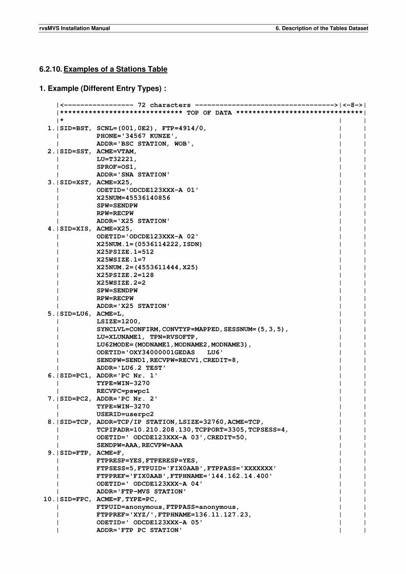
rvsMVS Installation Manual 6. Description of the Tables Dataset
6.2.10. Examples of a Stations Table
1. Example (Different Entry Types) : |<----------------- 72 characters ---------------------------------->|<-8->|
|****************************** TOP OF DATA *******************************|
|* | |
1.|SID=BST, SCNL=(001,0E2), FTP=4914/0, | |
| PHONE='34567 KUNZE', | |
| ADDR='BSC STATION, WOB', | |
2.|SID=SST, ACME=VTAM, | |
| LU=T32221, | |
| SPROF=OS1, | |
| ADDR='SNA STATION' | |
3.|SID=XST, ACME=X25, | |
| ODETID='ODCDE123XXX-A 01' | |
| X25NUM=45536140856 | |
| SPW=SENDPW | |
| RPW=RECPW | |
| ADDR='X25 STATION' | |
4.|SID=XIS, ACME=X25, | |
| ODETID='ODCDE123XXX-A 02' | |
| X25NUM.1=(0536114222,ISDN) | |
| X25PSIZE.1=512 | |
| X25WSIZE.1=7 | |
| X25NUM.2=(4553611444,X25) | |
| X25PSIZE.2=128 | |
| X25WSIZE.2=2 | |
| SPW=SENDPW | |
| RPW=RECPW | |
| ADDR='X25 STATION' | |
5.|SID=LU6, ACME=L, | |
| LSIZE=1200, | |
| SYNCLVL=CONFIRM,CONVTYP=MAPPED,SESSNUM=(5,3,5), | |
| LU=XLUNAME1, TPN=RVSOFTP, | |
| LU62MODE=(MODNAME1,MODNAME2,MODNAME3), | |
| ODETID='OXY34000001GEDAS LU6' | |
| SENDPW=SEND1,RECVPW=RECV1,CREDIT=8, | |
| ADDR='LU6.2 TEST' | |
6.|SID=PC1, ADDR='PC Nr. 1' | |
| TYPE=WIN-3270 | |
| RECVPC=pswpc1 | |
7.|SID=PC2, ADDR='PC Nr. 2' | |
| TYPE=WIN-3270 | |
| USERID=userpc2 | |
8.|SID=TCP, ADDR=TCP/IP STATION,LSIZE=32760,ACME=TCP, | |
| TCPIPADR=10.210.208.130,TCPPORT=3305,TCPSESS=4, | |
| ODETID=' ODCDE123XXX-A 03',CREDIT=50, | |
| SENDPW=AAA,RECVPW=AAA | |
9.|SID=FTP, ACME=F, | |
| FTPRESP=YES,FTPERESP=YES, | |
| FTPSESS=5,FTPUID='FIX0AAB',FTPPASS='XXXXXXX' | |
| FTPPREF='FIX0AAB',FTPHNAME='144.162.14.400' | |
| ODETID=' ODCDE123XXX-A 04' | |
| ADDR='FTP-MVS STATION' | |
10.|SID=FPC, ACME=F,TYPE=PC, | |
| FTPUID=anonymous,FTPPASS=anonymous, | |
| FTPPREF='XYZ/',FTPHNAME=136.11.127.23, | |
| ODETID=' ODCDE123XXX-A 05' | |
| ADDR='FTP PC STATION' | |
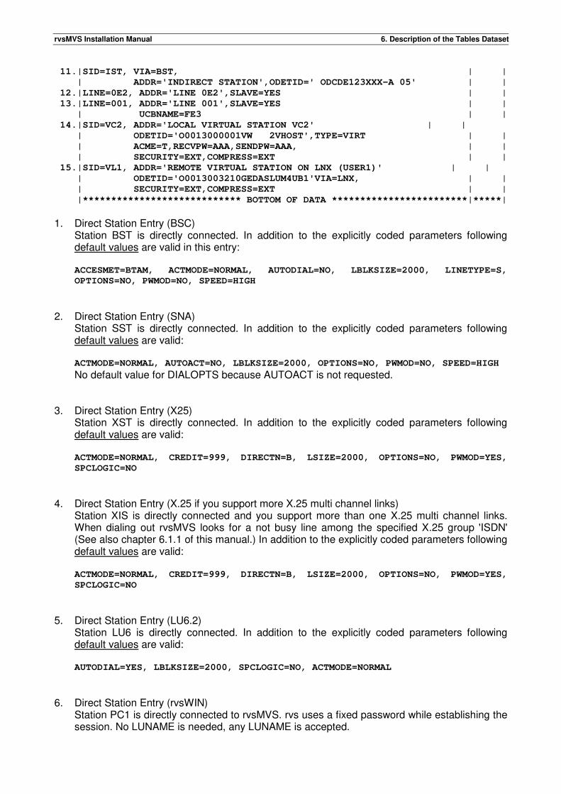
rvsMVS Installation Manual 6. Description of the Tables Dataset
11.|SID=IST, VIA=BST, | |
| ADDR='INDIRECT STATION',ODETID=' ODCDE123XXX-A 05' | |
12.|LINE=0E2, ADDR='LINE 0E2',SLAVE=YES | |
13.|LINE=001, ADDR='LINE 001',SLAVE=YES | |
| UCBNAME=FE3 | |
14.|SID=VC2, ADDR='LOCAL VIRTUAL STATION VC2' | |
| ODETID='O0013000001VW 2VHOST',TYPE=VIRT | |
| ACME=T,RECVPW=AAA,SENDPW=AAA, | |
| SECURITY=EXT,COMPRESS=EXT | |
15.|SID=VL1, ADDR='REMOTE VIRTUAL STATION ON LNX (USER1)' | |
| ODETID='O0013003210GEDASLUM4UB1'VIA=LNX, | |
| SECURITY=EXT,COMPRESS=EXT | |
|**************************** BOTTOM OF DATA ************************|*****|
1. Direct Station Entry (BSC)
Station BST is directly connected. In addition to the explicitly coded parameters following default values are valid in this entry:
ACCESMET=BTAM, ACTMODE=NORMAL, AUTODIAL=NO, LBLKSIZE=2000, LINETYPE=S,
OPTIONS=NO, PWMOD=NO, SPEED=HIGH
2. Direct Station Entry (SNA)
Station SST is directly connected. In addition to the explicitly coded parameters following default values are valid: ACTMODE=NORMAL, AUTOACT=NO, LBLKSIZE=2000, OPTIONS=NO, PWMOD=NO, SPEED=HIGH
No default value for DIALOPTS because AUTOACT is not requested. 3. Direct Station Entry (X25)
Station XST is directly connected. In addition to the explicitly coded parameters following default values are valid: ACTMODE=NORMAL, CREDIT=999, DIRECTN=B, LSIZE=2000, OPTIONS=NO, PWMOD=YES,
SPCLOGIC=NO
4. Direct Station Entry (X.25 if you support more X.25 multi channel links)
Station XIS is directly connected and you support more than one X.25 multi channel links. When dialing out rvsMVS looks for a not busy line among the specified X.25 group 'ISDN' (See also chapter 6.1.1 of this manual.) In addition to the explicitly coded parameters following default values are valid: ACTMODE=NORMAL, CREDIT=999, DIRECTN=B, LSIZE=2000, OPTIONS=NO, PWMOD=YES,
SPCLOGIC=NO
5. Direct Station Entry (LU6.2)
Station LU6 is directly connected. In addition to the explicitly coded parameters following default values are valid: AUTODIAL=YES, LBLKSIZE=2000, SPCLOGIC=NO, ACTMODE=NORMAL
6. Direct Station Entry (rvsWIN)
Station PC1 is directly connected to rvsMVS. rvs uses a fixed password while establishing the session. No LUNAME is needed, any LUNAME is accepted.
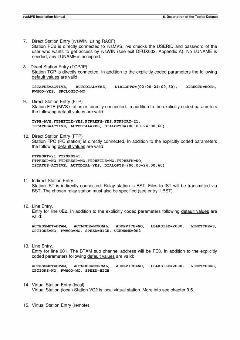
rvsMVS Installation Manual 6. Description of the Tables Dataset
7. Direct Station Entry (rvsWIN, using RACF)
Station PC2 is directly connected to rvsMVS. rvs checks the USERID and password of the user who wants to get access by rvsWIN (see exit DFUX002, Appendix A). No LUNAME is needed, any LUNAME is accepted.
8. Direct Station Entry (TCP/IP) Station TCP is directly connected. In addition to the explicitly coded parameters the following default values are valid: ISTATUS=ACTIVE, AUTODIAL=YES, DIALOPTS=(00:00-24:00,60), DIRECTN=BOTH,
PWMOD=YES, SPCLOGIC=NO
9. Direct Station Entry (FTP)
Station FTP (MVS station) is directly connected. In addition to the explicitly coded parameters the following default values are valid: TYPE=MVS,FTPHFILE=YES,FTPREFN=YES,FTPPORT=21,
ISTATUS=ACTIVE, AUTODIAL=YES, DIALOPTS=(00:00-24:00,60)
10. Direct Station Entry (FTP)
Station FPC (PC station) is directly connected. In addition to the explicitly coded parameters the following default values are valid: FTPPORT=21,FTPSESS=1,
FTPRESP=NO,FTPERESP=NO,FTPHFILE=NO,FTPREFN=NO,
ISTATUS=ACTIVE, AUTODIAL=YES, DIALOPTS=(00:00-24:00,60)
11. Indirect Station Entry. Station IST is indirectly connected. Relay station is BST. Files to IST will be transmitted via BST. The chosen relay station must also be specified (see entry 1,BST).
12. Line Entry. Entry for line 0E2. In addition to the explicitly coded parameters following default values are valid: ACCESSMET=BTAM, ACTMODE=NORMAL, ADDEVICE=NO, LBLKSIZE=2000, LINETYPE=S,
OPTIONS=NO, PWMOD=NO, SPEED=HIGH, UCBNAME=0E2
13. Line Entry. Entry for line 001. The BTAM sub channel address will be FE3. In addition to the explicitly coded parameters following default values are valid: ACCESSMET=BTAM, ACTMODE=NORMAL, ADDEVICE=NO, LBLKSIZE=2000, LINETYPE=S,
OPTIONS=NO, PWMOD=NO, SPEED=HIGH
14. Virtual Station Entry (local) Virtual Station (local) Station VC2 is local virtual station. More info see chapter 9.5.
15. Virtual Station Entry (remote)
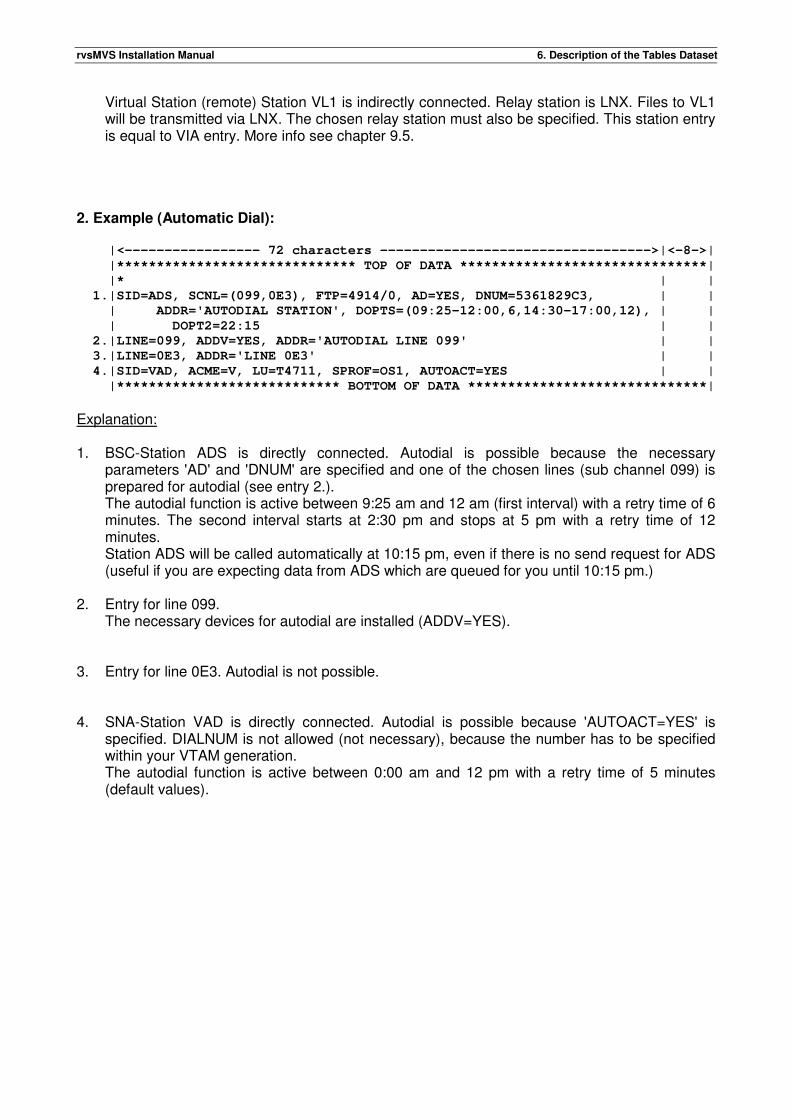
rvsMVS Installation Manual 6. Description of the Tables Dataset
Virtual Station (remote) Station VL1 is indirectly connected. Relay station is LNX. Files to VL1 will be transmitted via LNX. The chosen relay station must also be specified. This station entry is equal to VIA entry. More info see chapter 9.5.
2. Example (Automatic Dial): |<----------------- 72 characters ---------------------------------->|<-8->|
|****************************** TOP OF DATA *******************************|
|* | |
1.|SID=ADS, SCNL=(099,0E3), FTP=4914/0, AD=YES, DNUM=5361829C3, | |
| ADDR='AUTODIAL STATION', DOPTS=(09:25-12:00,6,14:30-17:00,12), | |
| DOPT2=22:15 | |
2.|LINE=099, ADDV=YES, ADDR='AUTODIAL LINE 099' | |
3.|LINE=0E3, ADDR='LINE 0E3' | |
4.|SID=VAD, ACME=V, LU=T4711, SPROF=OS1, AUTOACT=YES | |
|**************************** BOTTOM OF DATA ******************************|
Explanation: 1. BSC-Station ADS is directly connected. Autodial is possible because the necessary
parameters 'AD' and 'DNUM' are specified and one of the chosen lines (sub channel 099) is prepared for autodial (see entry 2.). The autodial function is active between 9:25 am and 12 am (first interval) with a retry time of 6 minutes. The second interval starts at 2:30 pm and stops at 5 pm with a retry time of 12 minutes. Station ADS will be called automatically at 10:15 pm, even if there is no send request for ADS (useful if you are expecting data from ADS which are queued for you until 10:15 pm.)
2. Entry for line 099.
The necessary devices for autodial are installed (ADDV=YES). 3. Entry for line 0E3. Autodial is not possible. 4. SNA-Station VAD is directly connected. Autodial is possible because 'AUTOACT=YES' is
specified. DIALNUM is not allowed (not necessary), because the number has to be specified within your VTAM generation. The autodial function is active between 0:00 am and 12 pm with a retry time of 5 minutes (default values).

rvsMVS Installation Manual 6. Description of the Tables Dataset
6.3. Special Transmission Protocols (rvs Program Profile Table)
(only used for the BSC component) The internal Program Profile Table contains a number of standard entries corresponding to the supported transmission protocols (chosen by stations parameter 'FTP'). In addition to these fixed profiles, some special profiles can be added using the dataset RVS.TABLES(PROGPROF). Special program profiles are necessary for example for BTAM leased lines. Creating special program profiles is described in 'rvsMVS Installation Manual', Appendix H.

rvsMVS Installation Manual 6. Description of the Tables Dataset
This page will be intentionally empty.
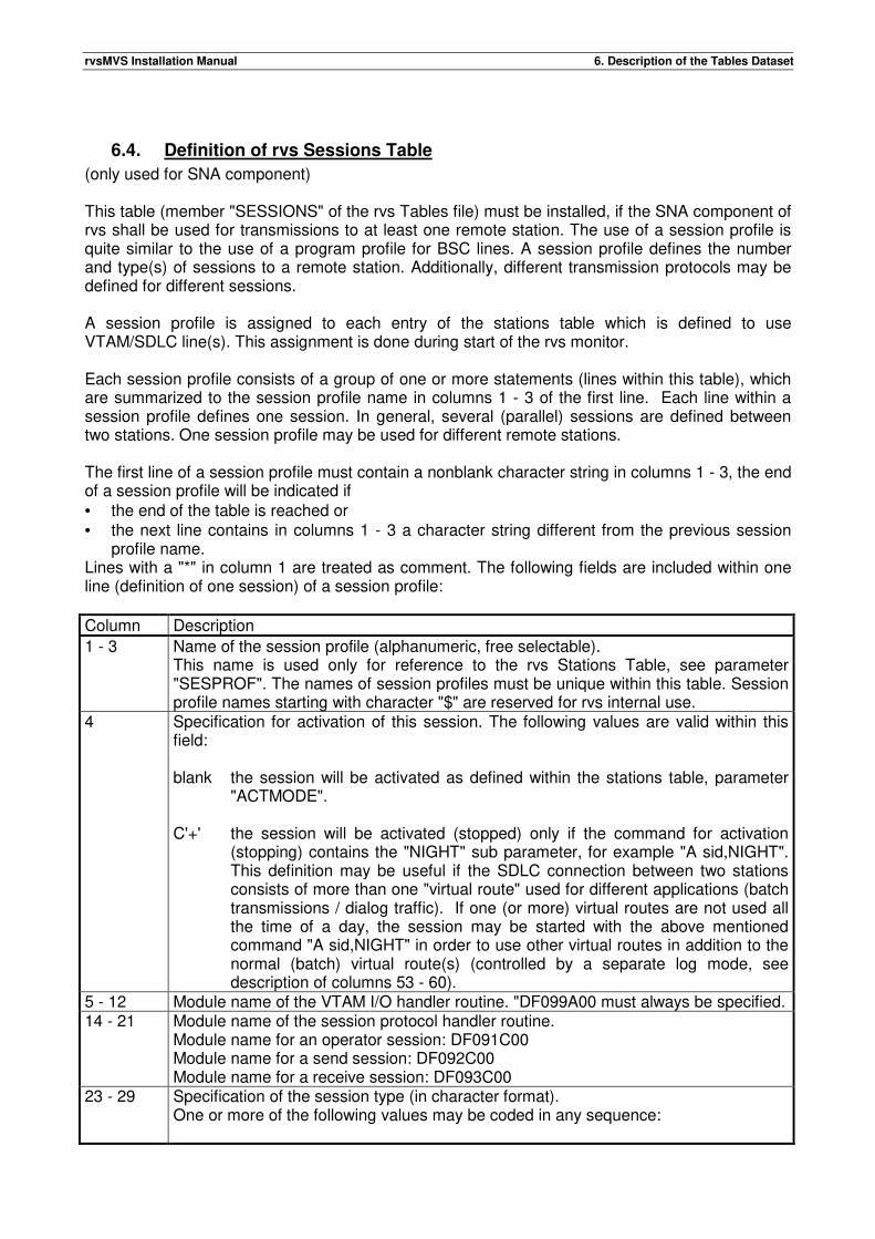
rvsMVS Installation Manual 6. Description of the Tables Dataset
6.4. Definition of rvs Sessions Table
(only used for SNA component) This table (member "SESSIONS" of the rvs Tables file) must be installed, if the SNA component of rvs shall be used for transmissions to at least one remote station. The use of a session profile is quite similar to the use of a program profile for BSC lines. A session profile defines the number and type(s) of sessions to a remote station. Additionally, different transmission protocols may be defined for different sessions. A session profile is assigned to each entry of the stations table which is defined to use VTAM/SDLC line(s). This assignment is done during start of the rvs monitor. Each session profile consists of a group of one or more statements (lines within this table), which are summarized to the session profile name in columns 1 - 3 of the first line. Each line within a session profile defines one session. In general, several (parallel) sessions are defined between two stations. One session profile may be used for different remote stations. The first line of a session profile must contain a nonblank character string in columns 1 - 3, the end of a session profile will be indicated if • the end of the table is reached or • the next line contains in columns 1 - 3 a character string different from the previous session
profile name. Lines with a "*" in column 1 are treated as comment. The following fields are included within one line (definition of one session) of a session profile:
Column Description
1 - 3 Name of the session profile (alphanumeric, free selectable). This name is used only for reference to the rvs Stations Table, see parameter "SESPROF". The names of session profiles must be unique within this table. Session profile names starting with character "$" are reserved for rvs internal use.
4 Specification for activation of this session. The following values are valid within this field: blank the session will be activated as defined within the stations table, parameter
"ACTMODE". C'+' the session will be activated (stopped) only if the command for activation
(stopping) contains the "NIGHT" sub parameter, for example "A sid,NIGHT". This definition may be useful if the SDLC connection between two stations consists of more than one "virtual route" used for different applications (batch transmissions / dialog traffic). If one (or more) virtual routes are not used all the time of a day, the session may be started with the above mentioned command "A sid,NIGHT" in order to use other virtual routes in addition to the normal (batch) virtual route(s) (controlled by a separate log mode, see description of columns 53 - 60).
5 - 12 Module name of the VTAM I/O handler routine. "DF099A00 must always be specified. 14 - 21 Module name of the session protocol handler routine.
Module name for an operator session: DF091C00 Module name for a send session: DF092C00 Module name for a receive session: DF093C00
23 - 29 Specification of the session type (in character format). One or more of the following values may be coded in any sequence:
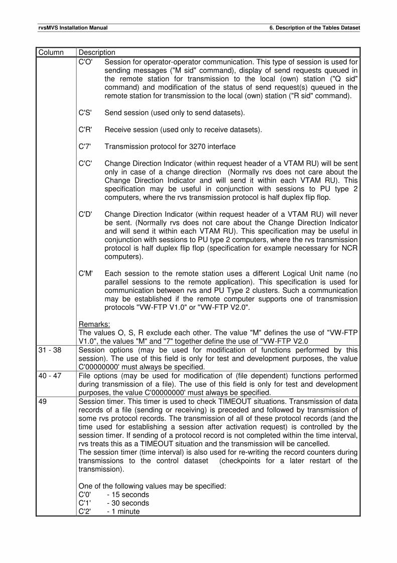
rvsMVS Installation Manual 6. Description of the Tables Dataset
Column Description
C'O' Session for operator-operator communication. This type of session is used for sending messages ("M sid" command), display of send requests queued in the remote station for transmission to the local (own) station ("Q sid" command) and modification of the status of send request(s) queued in the remote station for transmission to the local (own) station ("R sid" command).
C'S' Send session (used only to send datasets). C'R' Receive session (used only to receive datasets). C'7' Transmission protocol for 3270 interface C'C' Change Direction Indicator (within request header of a VTAM RU) will be sent
only in case of a change direction (Normally rvs does not care about the Change Direction Indicator and will send it within each VTAM RU). This specification may be useful in conjunction with sessions to PU type 2 computers, where the rvs transmission protocol is half duplex flip flop.
C'D' Change Direction Indicator (within request header of a VTAM RU) will never
be sent. (Normally rvs does not care about the Change Direction Indicator and will send it within each VTAM RU). This specification may be useful in conjunction with sessions to PU type 2 computers, where the rvs transmission protocol is half duplex flip flop (specification for example necessary for NCR computers).
C'M' Each session to the remote station uses a different Logical Unit name (no
parallel sessions to the remote application). This specification is used for communication between rvs and PU Type 2 clusters. Such a communication may be established if the remote computer supports one of transmission protocols "VW-FTP V1.0" or "VW-FTP V2.0".
Remarks: The values O, S, R exclude each other. The value "M" defines the use of "VW-FTP V1.0", the values "M" and "7" together define the use of "VW-FTP V2.0
31 - 38 Session options (may be used for modification of functions performed by this session). The use of this field is only for test and development purposes, the value C'00000000' must always be specified.
40 - 47 File options (may be used for modification of (file dependent) functions performed during transmission of a file). The use of this field is only for test and development purposes, the value C'00000000' must always be specified.
49 Session timer. This timer is used to check TIMEOUT situations. Transmission of data records of a file (sending or receiving) is preceded and followed by transmission of some rvs protocol records. The transmission of all of these protocol records (and the time used for establishing a session after activation request) is controlled by the session timer. If sending of a protocol record is not completed within the time interval, rvs treats this as a TIMEOUT situation and the transmission will be cancelled. The session timer (time interval) is also used for re-writing the record counters during transmissions to the control dataset (checkpoints for a later restart of the transmission). One of the following values may be specified: C'0' - 15 seconds C'1' - 30 seconds C'2' - 1 minute
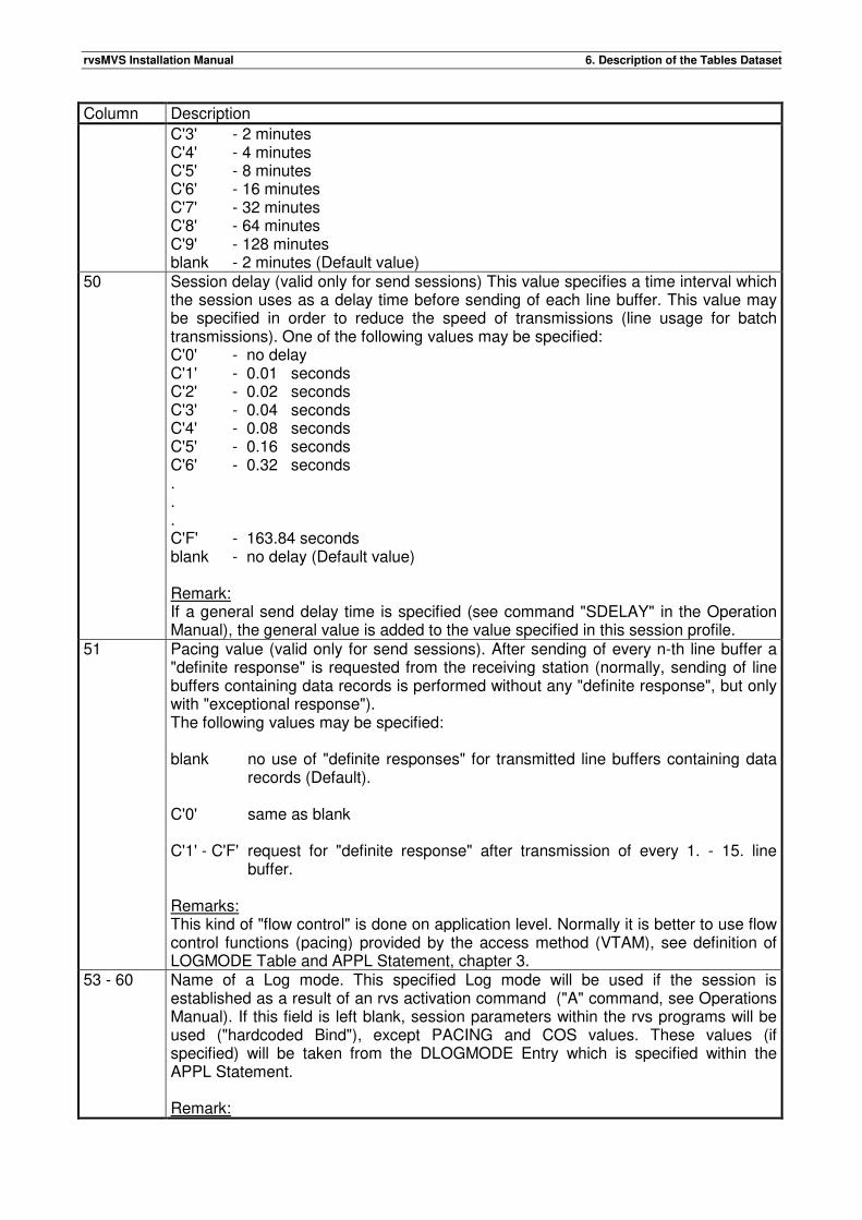
rvsMVS Installation Manual 6. Description of the Tables Dataset
Column Description
C'3' - 2 minutes C'4' - 4 minutes C'5' - 8 minutes C'6' - 16 minutes C'7' - 32 minutes C'8' - 64 minutes C'9' - 128 minutes blank - 2 minutes (Default value)
50 Session delay (valid only for send sessions) This value specifies a time interval which the session uses as a delay time before sending of each line buffer. This value may be specified in order to reduce the speed of transmissions (line usage for batch transmissions). One of the following values may be specified: C'0' - no delay C'1' - 0.01 seconds C'2' - 0.02 seconds C'3' - 0.04 seconds C'4' - 0.08 seconds C'5' - 0.16 seconds C'6' - 0.32 seconds . . . C'F' - 163.84 seconds blank - no delay (Default value) Remark: If a general send delay time is specified (see command "SDELAY" in the Operation Manual), the general value is added to the value specified in this session profile.
51 Pacing value (valid only for send sessions). After sending of every n-th line buffer a "definite response" is requested from the receiving station (normally, sending of line buffers containing data records is performed without any "definite response", but only with "exceptional response"). The following values may be specified: blank no use of "definite responses" for transmitted line buffers containing data
records (Default). C'0' same as blank C'1' - C'F' request for "definite response" after transmission of every 1. - 15. line
buffer. Remarks: This kind of "flow control" is done on application level. Normally it is better to use flow control functions (pacing) provided by the access method (VTAM), see definition of LOGMODE Table and APPL Statement, chapter 3.
53 - 60 Name of a Log mode. This specified Log mode will be used if the session is established as a result of an rvs activation command ("A" command, see Operations Manual). If this field is left blank, session parameters within the rvs programs will be used ("hardcoded Bind"), except PACING and COS values. These values (if specified) will be taken from the DLOGMODE Entry which is specified within the APPL Statement. Remark:
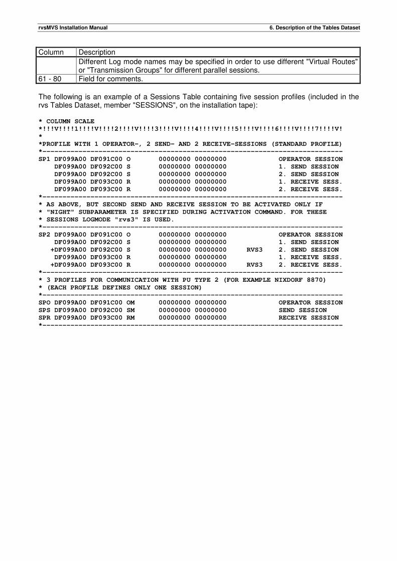
rvsMVS Installation Manual 6. Description of the Tables Dataset
Column Description
Different Log mode names may be specified in order to use different "Virtual Routes" or "Transmission Groups" for different parallel sessions.
61 - 80 Field for comments.
The following is an example of a Sessions Table containing five session profiles (included in the rvs Tables Dataset, member "SESSIONS", on the installation tape): * COLUMN SCALE
*!!!V!!!!1!!!!V!!!!2!!!!V!!!!3!!!!V!!!!4!!!!V!!!!5!!!!V!!!!6!!!!V!!!!7!!!!V!
*
*PROFILE WITH 1 OPERATOR-, 2 SEND- AND 2 RECEIVE-SESSIONS (STANDARD PROFILE)
*---------------------------------------------------------------------------
SP1 DF099A00 DF091C00 O 00000000 00000000 OPERATOR SESSION
DF099A00 DF092C00 S 00000000 00000000 1. SEND SESSION
DF099A00 DF092C00 S 00000000 00000000 2. SEND SESSION
DF099A00 DF093C00 R 00000000 00000000 1. RECEIVE SESS.
DF099A00 DF093C00 R 00000000 00000000 2. RECEIVE SESS.
*---------------------------------------------------------------------------
* AS ABOVE, BUT SECOND SEND AND RECEIVE SESSION TO BE ACTIVATED ONLY IF
* "NIGHT" SUBPARAMETER IS SPECIFIED DURING ACTIVATION COMMAND. FOR THESE
* SESSIONS LOGMODE "rvs3" IS USED.
*---------------------------------------------------------------------------
SP2 DF099A00 DF091C00 O 00000000 00000000 OPERATOR SESSION
DF099A00 DF092C00 S 00000000 00000000 1. SEND SESSION
+DF099A00 DF092C00 S 00000000 00000000 RVS3 2. SEND SESSION
DF099A00 DF093C00 R 00000000 00000000 1. RECEIVE SESS.
+DF099A00 DF093C00 R 00000000 00000000 RVS3 2. RECEIVE SESS.
*---------------------------------------------------------------------------
* 3 PROFILES FOR COMMUNICATION WITH PU TYPE 2 (FOR EXAMPLE NIXDORF 8870)
* (EACH PROFILE DEFINES ONLY ONE SESSION)
*---------------------------------------------------------------------------
SPO DF099A00 DF091C00 OM 00000000 00000000 OPERATOR SESSION
SPS DF099A00 DF092C00 SM 00000000 00000000 SEND SESSION
SPR DF099A00 DF093C00 RM 00000000 00000000 RECEIVE SESSION
*---------------------------------------------------------------------------
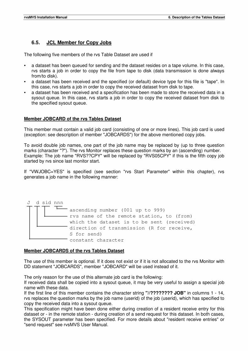
rvsMVS Installation Manual 6. Description of the Tables Dataset
6.5. JCL Member for Copy Jobs
The following five members of the rvs Table Dataset are used if • a dataset has been queued for sending and the dataset resides on a tape volume. In this case,
rvs starts a job in order to copy the file from tape to disk (data transmission is done always from/to disk).
• a dataset has been received and the specified (or default) device type for this file is "tape". In this case, rvs starts a job in order to copy the received dataset from disk to tape.
• a dataset has been received and a specification has been made to store the received data in a sysout queue. In this case, rvs starts a job in order to copy the received dataset from disk to the specified sysout queue.
Member JOBCARD of the rvs Tables Dataset This member must contain a valid job card (consisting of one or more lines). This job card is used (exception: see description of member "JOBCARDS") for the above mentioned copy jobs. To avoid double job names, one part of the job name may be replaced by (up to three question marks (character "?"). The rvs Monitor replaces these question marks by an (ascending) number. Example: The job name "RVS??CPY" will be replaced by "RVS05CPY" if this is the fifth copy job started by rvs since last monitor start. If "VWJOBC=YES" is specified (see section "rvs Start Parameter" within this chapter), rvs generates a job name in the following manner: Member JOBCARDS of the rvs Tables Dataset The use of this member is optional. If it does not exist or if it is not allocated to the rvs Monitor with DD statement "JOBCARDS", member "JOBCARD" will be used instead of it. The only reason for the use of this alternate job card is the following: If received data shall be copied into a sysout queue, it may be very useful to assign a special job name with these data. If the first line of this member contains the character string "//???????? JOB" in columns 1 - 14, rvs replaces the question marks by the job name (userid) of the job (userid), which has specified to copy the received data into a sysout queue. This specification might have been done either during creation of a resident receive entry for this dataset or - in the remote station - during creation of a send request for this dataset. In both cases, the SYSOUT parameter has been specified. For more details about "resident receive entries" or "send request" see rvsMVS User Manual.
J d sid nnn
ascending number (001 up to 999)
rvs name of the remote station, to (from)
which the dataset is to be sent (received)
direction of transmission (R for receive,
S for send)
constant character
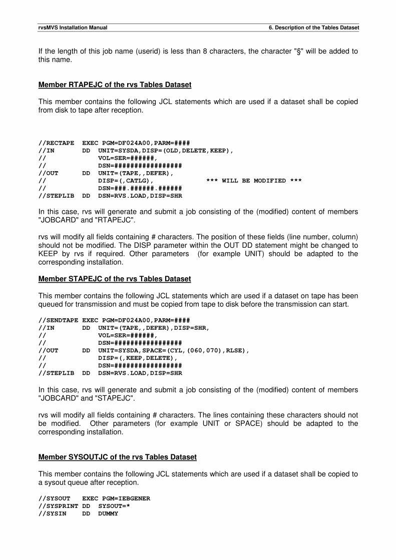
rvsMVS Installation Manual 6. Description of the Tables Dataset
If the length of this job name (userid) is less than 8 characters, the character "§" will be added to this name. Member RTAPEJC of the rvs Tables Dataset This member contains the following JCL statements which are used if a dataset shall be copied from disk to tape after reception. //RECTAPE EXEC PGM=DF024A00,PARM=####
//IN DD UNIT=SYSDA,DISP=(OLD,DELETE,KEEP),
// VOL=SER=######,
// DSN=#################
//OUT DD UNIT=(TAPE,,DEFER),
// DISP=(,CATLG), *** WILL BE MODIFIED ***
// DSN=###.######.######
//STEPLIB DD DSN=RVS.LOAD,DISP=SHR
In this case, rvs will generate and submit a job consisting of the (modified) content of members "JOBCARD" and "RTAPEJC". rvs will modify all fields containing # characters. The position of these fields (line number, column) should not be modified. The DISP parameter within the OUT DD statement might be changed to KEEP by rvs if required. Other parameters (for example UNIT) should be adapted to the corresponding installation. Member STAPEJC of the rvs Tables Dataset This member contains the following JCL statements which are used if a dataset on tape has been queued for transmission and must be copied from tape to disk before the transmission can start. //SENDTAPE EXEC PGM=DF024A00,PARM=####
//IN DD UNIT=(TAPE,,DEFER),DISP=SHR,
// VOL=SER=######,
// DSN=#################
//OUT DD UNIT=SYSDA,SPACE=(CYL,(060,070),RLSE),
// DISP=(,KEEP,DELETE),
// DSN=#################
//STEPLIB DD DSN=RVS.LOAD,DISP=SHR
In this case, rvs will generate and submit a job consisting of the (modified) content of members "JOBCARD" and "STAPEJC". rvs will modify all fields containing # characters. The lines containing these characters should not be modified. Other parameters (for example UNIT or SPACE) should be adapted to the corresponding installation. Member SYSOUTJC of the rvs Tables Dataset This member contains the following JCL statements which are used if a dataset shall be copied to a sysout queue after reception. //SYSOUT EXEC PGM=IEBGENER
//SYSPRINT DD SYSOUT=*
//SYSIN DD DUMMY
rvsMVS Installation Manual 6. Description of the Tables Dataset
//SYSUT1 DD DISP=(OLD,DELETE,KEEP),
// DSN=#################
//SYSUT2 DD SYSOUT=#
In this case, rvs will generate and submit a job consisting of the (modified) content of members "JOBCARD" (or "JOBCARDS", if available) and member "SYSOUTJC". rvs will modify all fields containing # characters. The lines containing these characters should not be modified. Other parameters (for example UNIT) should be adapted to the corresponding installation. Member FTPRVSJC of the rvs Tables Dataset This member contains the following JCL statements which are used for FTP file transmission (rvsFTP component only). //*MAIN SYSTEM=XY11
//RVSFTP1 EXEC PGM=FTP
//STEPLIB DD DSN=SYS1.LINKLIB,DISP=SHR
//SYSUDUMP DD SYSOUT=*
//SYSDUMP DD SYSOUT=*
//INPUT DD DISP=SHR,
// DSN=###.######.######
//OUTPUT DD DISP=OLD,
// DSN=###.######.######
//SYSPRINT DD SYSOUT=*
//RVSFTP2 EXEC PGM=IEBPTPCH
//SYSPRINT DD SYSOUT=*
//SYSUT1 DD DSN=*.RVSFTP1.OUTPUT,DISP=OLD
//SYSUT2 DD SYSOUT=*
PRINT MAXFLDS=1
RECORD FIELD=(80)
//RVSFTP3 EXEC PGM=IEFBR14
//NEW DD DISP=(NEW,CATLG,CATLG),
// DCB=*.RVSFTP1.INPUT,SPACE=(TRK,(1)),
// DSN=###.######.######
In this case, rvs will generate and submit a job consisting of the (modified) content of members "JOBCARDF" (if available) and member "FTPRVSJC". rvs will modify all fields containing # characters. The lines containing these characters should not be modified or removed. Other parameters (for example UNIT) should be adapted to the corresponding installation.

rvsMVS Installation Manual 6. Description of the Tables Dataset
This page will be intentionally empty.
rvsMVS Installation Manual 6. Description of the Tables Dataset
6.6. Control of rvs Messages
6.6.1. Control of Messages for Console and remote Operating
Starting with Release 1.4, Level 01, four new functions have been implemented to allow more control for the display of rvs messages on console and for the remote operating session. These functions are: 1. Suppression of messages on console 2. Display of messages on console 3. Suppression of messages for remote operating 4. Display of messages for remote operating Both display functions have highest priority in view of all other control algorithms for message processing. In particular the display of special 'P'-messages (which are normally only written to sysout protocols, see 6.6.2) is now possible. Another example for the display function is the general suppression of some messages, which however will be displayed only for a special remote station. The messages to be suppressed / displayed must be defined within a member of the rvs tables dataset. This member is called CNTLMSG member. The above functions may be used only if this member is allocated to the rvs monitor with DD-name CNTLMSG. If this allocation does not exist, rvs cannot activate the above functions. The control of additional sysout protocols (see 6.2.2) is not affected by these functions, this means that these functions do only control display/suppression of messages on console and for the remote operating session. The content of the CNTLMSG member may be changed at any time. It may be activated immediately by entering the command 'MSG,REFRESH' or 'MSG,R'. The member itself is divided into groups (subsets) of message definitions, each subset is assigned with a name. The reason for this division into different subsets is a high flexibility when selecting different subsets of messages to be suppressed / displayed on console/rem.operating. The selection of a subset of messages for a certain function may be controlled by the following commands: 'MSG,CNSLSUP=name' or 'MSG,CS=name' suppression of console messages 'MSG,CNSLDSPL=name' or 'MSG,CD=name' display of console messages 'MSG,RMOPSUP=name' or 'MSG,RS=name' suppression of rem.op. messages 'MSG,RMOPDSPL=name' or 'MSG,RD=name' display of rem.op. messages The assignments of message subsets to the different functions (and the fact which of the function is active or not) may be displayed with the command 'MSG,DISPLAY' or 'MSG,D'. After start of the rvs monitor (and after entering of the REFRESH command) the functions will be assigned with default subsets of messages (if defaults are defined, see below). If there is no default assignment for a function, this function remains inactive until the command 'MSG,fkt=name' is entered. 'fkt' denotes one of the four functions, see above.
rvsMVS Installation Manual 6. Description of the Tables Dataset
Each function may be set inactive by entering the command 'MSG,fkt=NONE'. Additionally there is a command to reset all functions to their default assignments: 'MSG,SETDEF' or 'MSG,S'. This command also displays the new assignments for all functions. Syntax of the CNTLMSG member • Lines starting with a '*' in column 1 are treated as a comment. • The length of a line (80 characters) may completely be used for definitions etc. • The first non-comment line must define the group (subset) name of the message subset.
Syntax: 'SUBSET=name' where 'name' is a string of up to 8 alphanumeric characters. No differences are made between small/capital letters: all input from the CNTLMSG member will be translated to capital letters before interpretation.
• After the definition of the subset name one (or more) default assignments for the different
functions may be done. Syntax:
'DEFAULT=CNSLSUP' default assignment for suppression of console messages 'DEFAULT=CNSLDSPL' default assignment for display of console messages 'DEFAULT=RMOPSUP' default assignment for suppression of rem.op. messages 'DEFAULT=RMOPDSPL' default assignment for display of rem.op. messages Subset definition and default assignment(s) must be separated by at least one blank.
• The default assignments become active after start of the rvs monitor as well as after entering
the command 'MSG,REFRESH'. If there are more than default assignments for the same function, only the first assignment will be accepted, further assignments are ignored.
• Other definitions within this line will be ignored. • After definition of the subset name (and default assignments) the messages of this subset may
be defined in the following lines. Definition of an 'empty' subset is syntactically accepted, but makes no sense.
• The end of a message subset will be recognized by 'end of file' or by the definition of a new
subset. • The messages itself must be defined generic, this means that always the first characters of the
message have to be specified. Especially each message has to start with the characters 'DF'. Modification of the message prefix (rvs start parameter 'MSGID=xx' does not affect processing of the suppression/display functions).
• All messages which match the same specified prefix will be processed (suppressed/displayed). • The definition of a message must comprise at least 3 characters (e.g. 'DF5'), the length of the
definition is only restricted by the length of a line (80 characters). • One line may contain several message definitions. • Message definitions within a line must be separated by one (or more) blanks. If a message
definition itself contains blanks, it must be enclosed by the characters '>' and '<'. Example:
rvsMVS Installation Manual 6. Description of the Tables Dataset
*---------------------------------------------------------------*
* CNTLMSG MEMBER *
*---------------------------------------------------------------*
*
* START MESSAGES OF SNA COMPONENT
*
SUBSET=COMPSNA1
DF3601 DF3713
*
* START AND TERMINATION MESSAGE OF X25/LU62 COMPONENT
*
SUBSET=COMPX251
DF9409 DF9415
*
* COMBINATION COMPSNA1 + COMPX251
*
SUBSET=STANDARD
DF3601 DF3713 DF9409 DF9415
*
* OUTPUT OF DD-COMMAND
*
SUBSET=DISPLAY1 DEFAULT=CNSLDSPL DEFAULT=RMOPDSPL
DF5211
*
* JOBSTART MESSAGE FOR STATION X01
*
SUBSET=JOBSTRT1
>DF5801I *R-X01*<
Remark: The example above in included in the tables dataset of the distribution tape.
6.6.2. Additional SYSOUT protocols
Most, but not all of the rvs messages are displayed on the operators console. For example, all messages containing the character 'P' in column 7 of the message identifier, are not displayed on console. In some cases (for example problem determination) it is useful to have more information about the activity of the rvs monitor. Because of such reasons it is possible, to define one (or more) SYSOUT protocols for the rvs monitor. The content of these protocols may be selected by message identifiers. To define an (additional) SYSOUT protocol, the following things must be done: 1. Two additional DD statements must be inserted into the rvs start procedure for one SYSOUT
protocol. The first one is used to allocate a member of the rvs tables dataset, which contains the information about the messages to be printed on the protocol (see below). The second one is used to allocate the SYSOUT protocol (output file) itself. These two DD statements build a pair with the DD names MSGIDnn and SYSWTOnn, where nn is a number between 01 and 09 or blank. The value of "nn" must be the same within one pair of DD names. Remark: If you want to look to SYSWTOnn protocols during the run of the rvs monitor,
please use a pre-allocated (not empty) file within the DD statement and allocate it with DISP=SHR. As soon as the records have been written onto disk it is possible to look at them (e.g. with ISPF BROWSE).
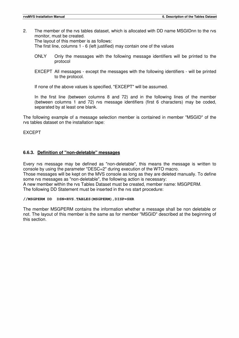
rvsMVS Installation Manual 6. Description of the Tables Dataset
2. The member of the rvs tables dataset, which is allocated with DD name MSGIDnn to the rvs monitor, must be created. The layout of this member is as follows: The first line, columns 1 - 6 (left justified) may contain one of the values ONLY Only the messages with the following message identifiers will be printed to the
protocol EXCEPT All messages - except the messages with the following identifiers - will be printed
to the protocol. If none of the above values is specified, "EXCEPT" will be assumed. In the first line (between columns 8 and 72) and in the following lines of the member (between columns 1 and 72) rvs message identifiers (first 6 characters) may be coded, separated by at least one blank.
The following example of a message selection member is contained in member "MSGID" of the rvs tables dataset on the installation tape: EXCEPT
6.6.3. Definition of "non-deletable" messages
Every rvs message may be defined as "non-deletable", this means the message is written to console by using the parameter "DESC=2" during execution of the WTO macro. Those messages will be kept on the MVS console as long as they are deleted manually. To define some rvs messages as "non-deletable", the following action is necessary: A new member within the rvs Tables Dataset must be created, member name: MSGPERM. The following DD Statement must be inserted in the rvs start procedure: //MSGPERM DD DSN=RVS.TABLES(MSGPERM),DISP=SHR
The member MSGPERM contains the information whether a message shall be non deletable or not. The layout of this member is the same as for member "MSGID" described at the beginning of this section.
rvsMVS Installation Manual 6. Description of the Tables Dataset
6.7. Automatically executed rvs commands
The member "START" of the rvs Tables Dataset may be used to specify rvs commands, which are to be executed immediately after start of the rvs Monitor. So it is possible - for example - to activate one (or more) lines after start of rvs automatically. The member "START" may be empty or may be totally left out of the rvs start procedure. If one (or more) commands shall be executed automatically after start of rvs, the following rules must be noticed: • Every command must be specified on a separate line within the member. • Every command must start on column 1.
• Blank lines or comment lines are not allowed. The rvs Tables Dataset on the installation tape contains an empty START member.

rvsMVS Installation Manual 6. Description of the Tables Dataset
This page will be intentionally empty.
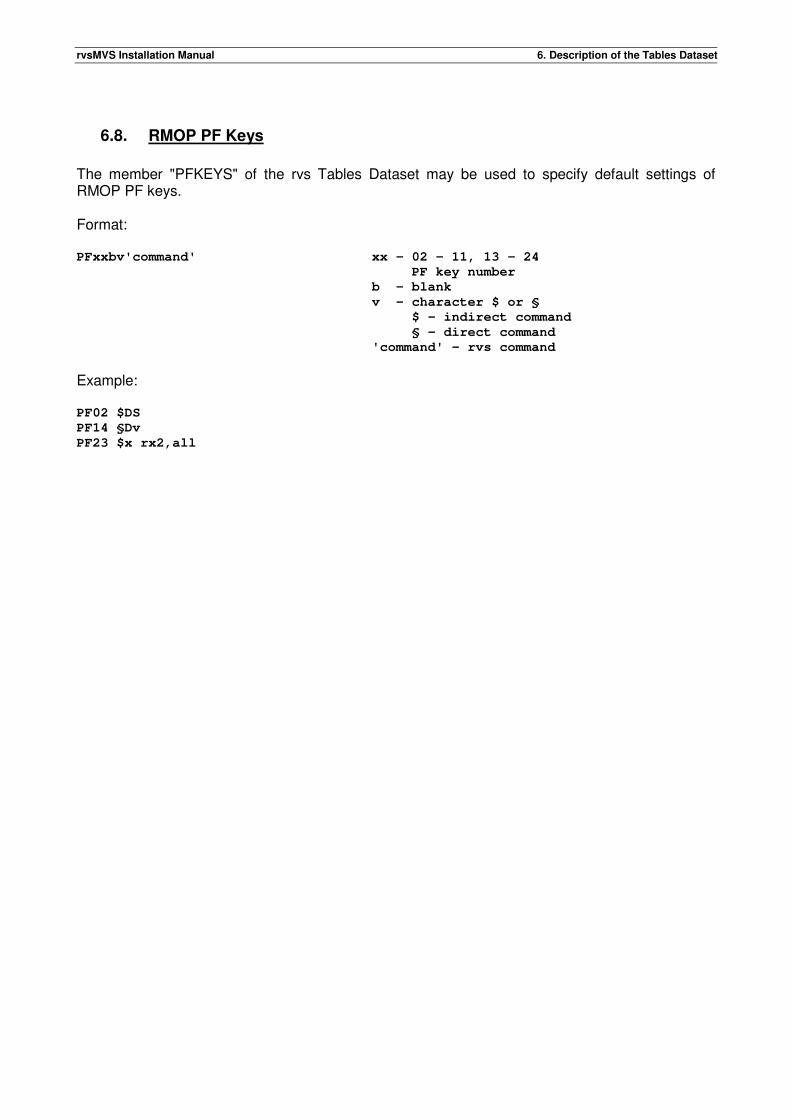
rvsMVS Installation Manual 6. Description of the Tables Dataset
6.8. RMOP PF Keys
The member "PFKEYS" of the rvs Tables Dataset may be used to specify default settings of RMOP PF keys. Format: PFxxbv'command' xx - 02 - 11, 13 - 24
PF key number
b - blank
v - character $ or §
$ - indirect command
§ - direct command
'command' - rvs command
Example: PF02 $DS
PF14 §Dv
PF23 $x rx2,all

rvsMVS Installation Manual 6. Description of the Tables Dataset
This page will be intentionally empty.
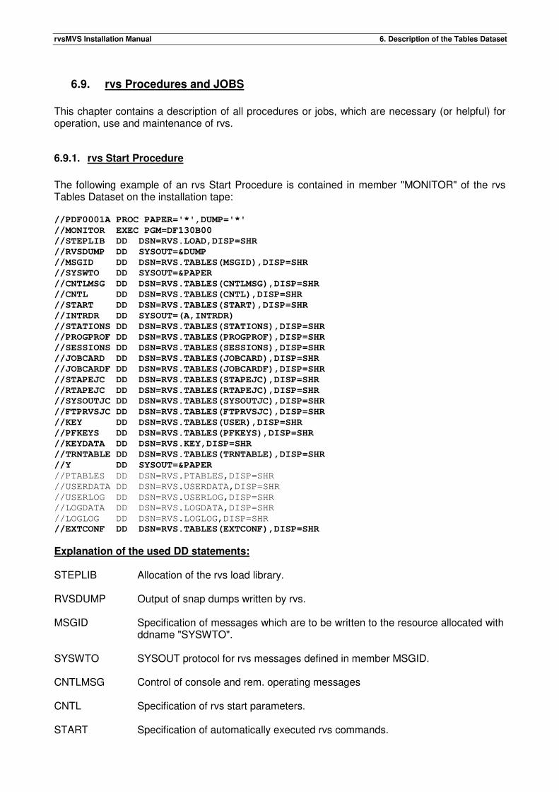
rvsMVS Installation Manual 6. Description of the Tables Dataset
6.9. rvs Procedures and JOBS
This chapter contains a description of all procedures or jobs, which are necessary (or helpful) for operation, use and maintenance of rvs.
6.9.1. rvs Start Procedure
The following example of an rvs Start Procedure is contained in member "MONITOR" of the rvs Tables Dataset on the installation tape: //PDF0001A PROC PAPER='*',DUMP='*'
//MONITOR EXEC PGM=DF130B00
//STEPLIB DD DSN=RVS.LOAD,DISP=SHR
//RVSDUMP DD SYSOUT=&DUMP
//MSGID DD DSN=RVS.TABLES(MSGID),DISP=SHR
//SYSWTO DD SYSOUT=&PAPER
//CNTLMSG DD DSN=RVS.TABLES(CNTLMSG),DISP=SHR
//CNTL DD DSN=RVS.TABLES(CNTL),DISP=SHR
//START DD DSN=RVS.TABLES(START),DISP=SHR
//INTRDR DD SYSOUT=(A,INTRDR)
//STATIONS DD DSN=RVS.TABLES(STATIONS),DISP=SHR
//PROGPROF DD DSN=RVS.TABLES(PROGPROF),DISP=SHR
//SESSIONS DD DSN=RVS.TABLES(SESSIONS),DISP=SHR
//JOBCARD DD DSN=RVS.TABLES(JOBCARD),DISP=SHR
//JOBCARDF DD DSN=RVS.TABLES(JOBCARDF),DISP=SHR
//STAPEJC DD DSN=RVS.TABLES(STAPEJC),DISP=SHR
//RTAPEJC DD DSN=RVS.TABLES(RTAPEJC),DISP=SHR
//SYSOUTJC DD DSN=RVS.TABLES(SYSOUTJC),DISP=SHR
//FTPRVSJC DD DSN=RVS.TABLES(FTPRVSJC),DISP=SHR
//KEY DD DSN=RVS.TABLES(USER),DISP=SHR
//PFKEYS DD DSN=RVS.TABLES(PFKEYS),DISP=SHR
//KEYDATA DD DSN=RVS.KEY,DISP=SHR
//TRNTABLE DD DSN=RVS.TABLES(TRNTABLE),DISP=SHR
//Y DD SYSOUT=&PAPER
//PTABLES DD DSN=RVS.PTABLES,DISP=SHR
//USERDATA DD DSN=RVS.USERDATA,DISP=SHR
//USERLOG DD DSN=RVS.USERLOG,DISP=SHR
//LOGDATA DD DSN=RVS.LOGDATA,DISP=SHR
//LOGLOG DD DSN=RVS.LOGLOG,DISP=SHR
//EXTCONF DD DSN=RVS.TABLES(EXTCONF),DISP=SHR
Explanation of the used DD statements: STEPLIB Allocation of the rvs load library.
RVSDUMP Output of snap dumps written by rvs.
MSGID Specification of messages which are to be written to the resource allocated with
ddname "SYSWTO".
SYSWTO SYSOUT protocol for rvs messages defined in member MSGID.
CNTLMSG Control of console and rem. operating messages
CNTL Specification of rvs start parameters.
START Specification of automatically executed rvs commands.
rvsMVS Installation Manual 6. Description of the Tables Dataset
INTRDR Allocation of Internal Reader (for example used for job start after reception of a
dataset). Since version 4.01.00: If this statement is used, dynamic allocation / deallocation and open/close are used once only.
STATIONS Allocation of rvs Stations Table (contains information about all connected stations).
SESSIONS Allocation of rvs Sessions Table (information about the transmission protocol and other specifications, which are to be used for the communication with certain stations. This information is used for all transmissions working with the SNA component.
JOBCARD Allocation of a valid job card (used for example if received datasets are to be copied to tape or sysout)
JOBCARDF Allocation of a valid job card (used for jobs of the FTP component)
STAPEJC Job control used if a dataset queued for transmission resides on tape and must be copied to disk before transmission.
RTAPEJC Job control used if a dataset is to be copied to tape after reception (for example if the start parameter "DDEVTYP=TAPE" is active and no other control for reception of this dataset has been specified)
SYSOUTJC Job control to copy a received dataset into a SYSOUT queue (for example if the SYSOUT parameter has been specified within a resident receive entry for this dataset)
FTPRVSJC Job control used for FTP file transfer (FTP component only)
KEY Specification of member USER with license parameters
PFKEYS Specification of member PFKEYS with definitions of RMOP PF keys (optional)
KEYDATA rvs Security Key Data data set.
TRNTABLE
Code Translation Tables (optional, see chapter 6.11)
Y Output results of the Y-commands written by rvs (optional)
EXTCONF Configuration dataset for extended tracing of XOT and online encryption
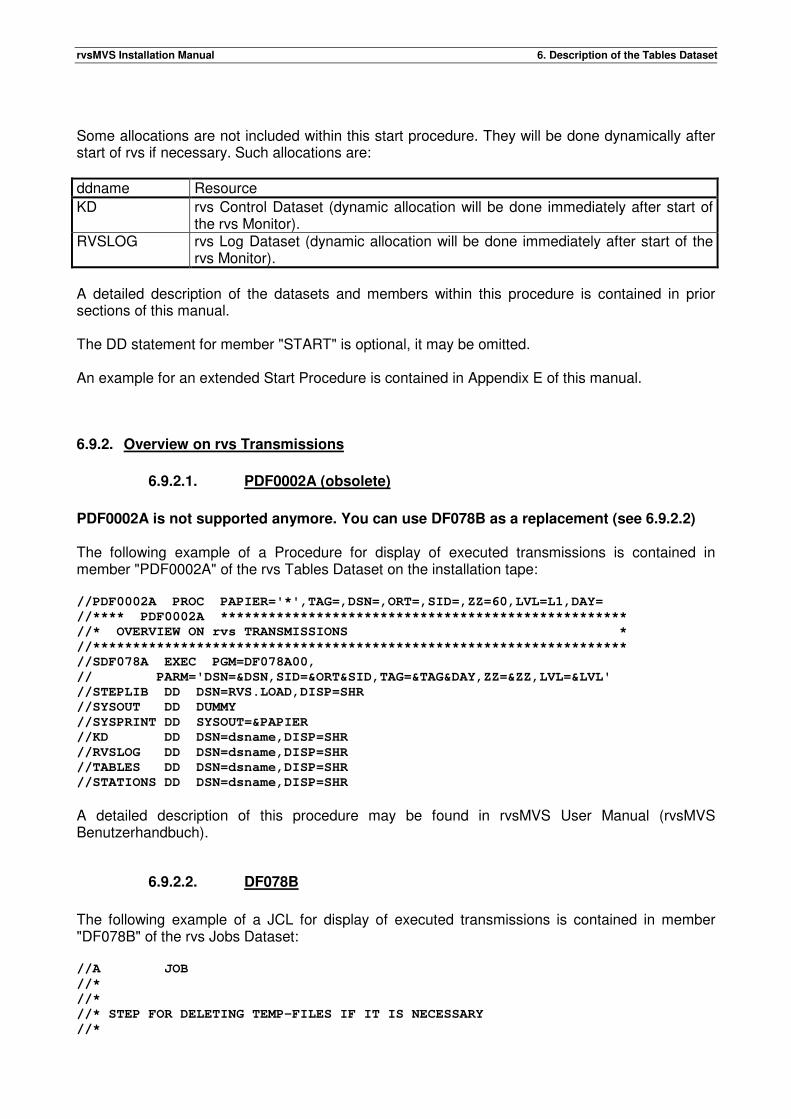
rvsMVS Installation Manual 6. Description of the Tables Dataset
Some allocations are not included within this start procedure. They will be done dynamically after start of rvs if necessary. Such allocations are:
ddname Resource
KD rvs Control Dataset (dynamic allocation will be done immediately after start of the rvs Monitor).
RVSLOG rvs Log Dataset (dynamic allocation will be done immediately after start of the rvs Monitor).
A detailed description of the datasets and members within this procedure is contained in prior sections of this manual. The DD statement for member "START" is optional, it may be omitted. An example for an extended Start Procedure is contained in Appendix E of this manual.
6.9.2. Overview on rvs Transmissions
6.9.2.1. PDF0002A (obsolete)
PDF0002A is not supported anymore. You can use DF078B as a replacement (see 6.9.2.2) The following example of a Procedure for display of executed transmissions is contained in member "PDF0002A" of the rvs Tables Dataset on the installation tape: //PDF0002A PROC PAPIER='*',TAG=,DSN=,ORT=,SID=,ZZ=60,LVL=L1,DAY=
//**** PDF0002A ***************************************************
//* OVERVIEW ON rvs TRANSMISSIONS *
//*******************************************************************
//SDF078A EXEC PGM=DF078A00,
// PARM='DSN=&DSN,SID=&ORT&SID,TAG=&TAG&DAY,ZZ=&ZZ,LVL=&LVL'
//STEPLIB DD DSN=RVS.LOAD,DISP=SHR
//SYSOUT DD DUMMY
//SYSPRINT DD SYSOUT=&PAPIER
//KD DD DSN=dsname,DISP=SHR
//RVSLOG DD DSN=dsname,DISP=SHR
//TABLES DD DSN=dsname,DISP=SHR
//STATIONS DD DSN=dsname,DISP=SHR
A detailed description of this procedure may be found in rvsMVS User Manual (rvsMVS Benutzerhandbuch).
6.9.2.2. DF078B
The following example of a JCL for display of executed transmissions is contained in member "DF078B" of the rvs Jobs Dataset: //A JOB
//*
//*
//* STEP FOR DELETING TEMP-FILES IF IT IS NECESSARY
//*
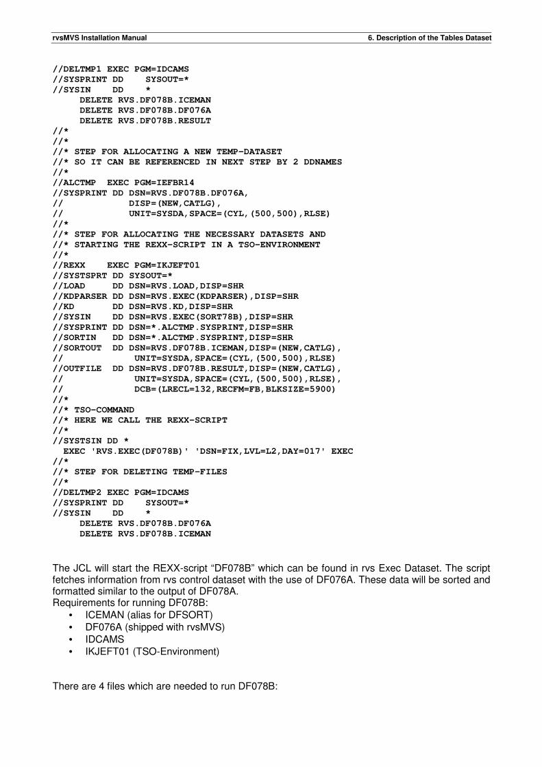
rvsMVS Installation Manual 6. Description of the Tables Dataset
//DELTMP1 EXEC PGM=IDCAMS
//SYSPRINT DD SYSOUT=*
//SYSIN DD *
DELETE RVS.DF078B.ICEMAN
DELETE RVS.DF078B.DF076A
DELETE RVS.DF078B.RESULT
//*
//*
//* STEP FOR ALLOCATING A NEW TEMP-DATASET
//* SO IT CAN BE REFERENCED IN NEXT STEP BY 2 DDNAMES
//*
//ALCTMP EXEC PGM=IEFBR14
//SYSPRINT DD DSN=RVS.DF078B.DF076A,
// DISP=(NEW,CATLG),
// UNIT=SYSDA,SPACE=(CYL,(500,500),RLSE)
//*
//* STEP FOR ALLOCATING THE NECESSARY DATASETS AND
//* STARTING THE REXX-SCRIPT IN A TSO-ENVIRONMENT
//*
//REXX EXEC PGM=IKJEFT01
//SYSTSPRT DD SYSOUT=*
//LOAD DD DSN=RVS.LOAD,DISP=SHR
//KDPARSER DD DSN=RVS.EXEC(KDPARSER),DISP=SHR
//KD DD DSN=RVS.KD,DISP=SHR
//SYSIN DD DSN=RVS.EXEC(SORT78B),DISP=SHR
//SYSPRINT DD DSN=*.ALCTMP.SYSPRINT,DISP=SHR
//SORTIN DD DSN=*.ALCTMP.SYSPRINT,DISP=SHR
//SORTOUT DD DSN=RVS.DF078B.ICEMAN,DISP=(NEW,CATLG),
// UNIT=SYSDA,SPACE=(CYL,(500,500),RLSE)
//OUTFILE DD DSN=RVS.DF078B.RESULT,DISP=(NEW,CATLG),
// UNIT=SYSDA,SPACE=(CYL,(500,500),RLSE),
// DCB=(LRECL=132,RECFM=FB,BLKSIZE=5900)
//*
//* TSO-COMMAND
//* HERE WE CALL THE REXX-SCRIPT
//*
//SYSTSIN DD *
EXEC 'RVS.EXEC(DF078B)' 'DSN=FIX,LVL=L2,DAY=017' EXEC
//*
//* STEP FOR DELETING TEMP-FILES
//*
//DELTMP2 EXEC PGM=IDCAMS
//SYSPRINT DD SYSOUT=*
//SYSIN DD *
DELETE RVS.DF078B.DF076A
DELETE RVS.DF078B.ICEMAN
The JCL will start the REXX-script “DF078B” which can be found in rvs Exec Dataset. The script fetches information from rvs control dataset with the use of DF076A. These data will be sorted and formatted similar to the output of DF078A. Requirements for running DF078B:
• ICEMAN (alias for DFSORT) • DF076A (shipped with rvsMVS) • IDCAMS • IKJEFT01 (TSO-Environment)
There are 4 files which are needed to run DF078B:
rvsMVS Installation Manual 6. Description of the Tables Dataset
RVS.JOBS(DF078B) JCL for allocating necessary datasets and starting the REXX-script.
RVS.EXEC(DF078B) The main REXX-script which formats the output. RVS.EXEC(SORT78B) Configuration dataset for sort routine (ICEMAN). RVS.EXEC(KDPARSER) REXX-script for parsing the raw data of rvsMVS
control dataset. For executing the program there are 3 datasets necessary: RVS.DF078B.RESULT This dataset will contain the formatted output of
DF078B. RVS.DF078B.ICEMAN This dataset will be used as output file for the sort
routine (ICEMAN). RVS.DF078B.DF076A This dataset will be used as the output file for DF076A
and contains the raw data of the control dataset. The names of the datasets can be changed according your environment. The JCL contains several Steps:
DELTMP1
This step deletes the temporary datasets which are needed to run the script and the result dataset.
ALCTMP
This step allocates the output dataset for DF076A (for the raw data from control dataset). The step is necessary because the file will be used by two DD-Statements. Allocations:
• SYSPRINT the output dataset for DF076A
REXX
This step starts the REXX-script ion a TSO-Environment. Allocations:
• SYSTSPRT REXX-Messages (Sysout=*) • LOAD rvsMVS-Loadlib • KDPARSER the REXX-Script for parsing the control dataset • KD rvsMVS control dataset • SYSIN configuration dataset for sort routine • SYSPRINT reference to DF076A output dataset • SORTIN reference to DF076A output dataset • SORTOUT the output dataset for sort routine (ICEMAN) • OUTFILE dataset which contains the formatted output • SYSTSIN start of the REXX-Script please use the following format:
EXEC 'RVS.EXEC(DF078B)' 'OPTIONS' EXEC
DELTMP2
This step deletes the temporary datasets.
rvsMVS Installation Manual 6. Description of the Tables Dataset
The configuration dataset of the sort routine may be changed according to your environment. Please refer manual for DFSORT for further information. A detailed description of this procedure may be found in rvsMVS User Manual (rvsMVS Benutzerhandbuch).
6.9.3. Deleting old entries from the rvs Control Dataset
The rvs Control dataset contains - among others - records with information about executed transmissions of the last time. These records are not deleted automatically after some time. So it is necessary - in order to avoid space problems within the rvs Control Dataset - to execute the following procedure from time to time (for example once a week). This procedure is contained in member "PDF0009A" of the rvs Tables Dataset on the installation tape: //PDF0009A PROC PAPIER='*',R=RESERVE,DAYS=07,INTV=0
//**** PDF0009A ***************************************************
//* DELETING OF OLD RECORDS FROM rvs CONTROL DATASET *
//*******************************************************************
//SDF079B EXEC PGM=DF079B00,PARM='&R,DAYS=&DAYS,INTV=&INTV'
//STEPLIB DD DSN=RVS.LOAD,DISP=SHR
//SYSPRINT DD SYSOUT=&PAPIER
//KD DD DSN=dsname,DISP=SHR
Description of parameters for program DF079B00: "RESERVE" or "NORESERVE"
indicates whether deleting of records is to be done with exclusive control for the rvs Control dataset or not. If access to the rvs Control dataset is done from different systems, "RESERVE" should always be specified. Default value: "RESERVE".
DAYS=nnn ARDAYS=nnn
This parameter indicates the number of days, for which the information about executed transmissions is at least to be kept. This means, that only records older than "nn" days will be deleted. "nnn" may be a value between 3 and 365. Execution of this procedure results only in deleting of records representing complete transmissions. Send requests which are not complete processed or resident receive entries will never be deleted by this procedure. AR-Records will be deleted, as soon as end-date is outside nnn days. Make sure to set the parameter &#DFDAYKE in the start-CLIST for the ISPF-Panels to the same value. Default value: "DAYS=7". This parameter indicates the number of days, for which the information about incomplete receive transmissions (AR-Records without end-date) will be kept. Instead of end-date, either start-date or, if unset, ready-date will be used to calculate the age. “nnn” may be a value between 3 and 365. Default value: “ARDAYS=90”.
INTV=mm This parameter specifies the number of days, in which deleting of records will not be performed more than one time. This means, deleting of records will only be done if this procedure has not been executed within the last "mm" days. Default value: "INTV=0".
rvsMVS Installation Manual 6. Description of the Tables Dataset
INTRPT=YES This parameter allows interrupt processing. Execution of this program will be
interrupted every 2 seconds followed by a wait time of 7 seconds. This kind of processing avoids long time periods in which the control dataset is in exclusive control of only one job. Default value: "INTRPT=NO".
Remark: The rvs Control dataset will be allocated dynamically if this procedure is executed. The used ddname is "KD".
6.9.4. Saving and Recovery of the rvs Control dataset
The rvs control dataset is the central information file within rvs. The content of this file changes with every transmission, thus the requirements for a restore of this file in case of a catalog failure or disk error are different from those for other datasets. rvs has its own method to reconstruct a damaged control dataset without loss of any information at any time. The concept for this is as follows: • All modifications of the rvs control dataset are recorded within the rvs log dataset. If this log
dataset is full, any update of the control dataset is terminated by a user abend. • At certain times (depending on the number of transmissions and the size of the log dataset) a
copy of control- and log dataset must be done. Together with this copy, the Log dataset is marked empty again (PDF0014A).
• A damaged control dataset can be recovered without loss of any information, if the following
steps are performed: - deleting the damaged file - creation of a new control dataset - copy of the last control dataset backup to the new file - merging of the log dataset (content since last backup copy of control- and log dataset)
into the new file The following two procedures are used for realization of the above described concept. They are part of installation artifact TABLES Use members PDF0014A and PDF0015A (resp. PDF0015B in case of SMS) of the rvs Dataset TABLES. //PDF0014A PROC PAPIER='*',NOSAVE=00
//**** PDF0014A *****************************************************
//* BACKUP OF rvs CONTROLDATASET AND LOG FILE & RESET OF LOG FILE *
//* *
//* USE IT IN CASE OF: *
//* LOG FILE IS FULL (JOB CAN RUN WITHOUT STOPPING THE MONITOR) *
//* OR *
//* CONTROL DATASET MUST BE RECOVERED (IF IT IS DAMAGED) *
//* CONTROL DATASET MUST BE RE-ORGANIZED (IF IT IS FULL) *
//* (MONITOR MUST BE STOPPED + PDF0015A) *
//*********************************************************************
//SDF014A EXEC PGM=DF072A00,PARM='NOSAVE=&NOSAVE'
//STEPLIB DD DSN=RVS.LOAD,DISP=SHR
//SYSPRINT DD SYSOUT=&PAPIER
//KD DD DSN=RVS.KD,DISP=SHR
//KDSAVE DD DSN=RVS.KD.SAVE,DISP=SHR
//RVSLOG DD DSN=RVS.LOG,DISP=SHR
//LOGSAVE DD DSN=RVS.LOG.SAVE,DISP=SHR
rvsMVS Installation Manual 6. Description of the Tables Dataset
Remarks The parameter "NOSAVE=nn" controls if a copy of control- and log dataset is to be created or not. "nn" specifies (in percent) the usage (filling) of the log dataset and may be a value between 00 and 99. A copy of control- and Log-dataset is performed only if the log dataset is at least filled by nn %. This allows the combination of this procedure with the rvs Start procedure without creating backup copies during every start of rvs. See Appendix E of this manual for such a combination. If execution of the procedure results in creation of backup copies, the program DF072A00 ends with return code 0, if backup copies are suppressed because of the parameter "NOSAVE=nn", a return code of 4 is set by DF072A00. The datasets RVS.KDSAVE and RVS.LOGSAVE must be created before execution of this procedure or the allocation must be done with "DISP=(NEW,...). Both datasets are sequential files. RVS.KDSAVE requires 1/3 of the space which is allocated to RVS.KD, RVS.LOGSAVE requires the same space as RVS.LOG. Specification of DCB attributes is not necessary, program DF072A00 uses hard coded values in each case. These are:
LRECL Block size Record Format
RVS.KDSAVE 1000 6000 variable blocked (VB) RVS.LOGSAVE 1000 6000 fixed blocked (FB)
Another control parameter may be specified for program DF072A00: LOGSAVE=ASY. If this parameter is specified, no copy of the log dataset will be created. Only the currently used data area of the log dataset will be marked in this file. Specification of this parameter may be useful to reduce the time used for the backup copy of the control dataset. No other access to the control dataset may be done within this time (RESERVE). The default behavior of DF072A00 is exclusive control (RESERVE). It can be changed to NORESERVE by parameter PARM='NORESERVE,...' in the exec-statement of PDF0014A. A backup copy of the log dataset (for example used for statistics) may be obtained after execution of program DF072A00. This copy does not require exclusive control (RESERVE), this means updates of the control dataset may be done even if the backup copy of the log dataset is created. For this copy, the following job step may be used: //LOGSAVE EXEC PGM=DF084A00
//SYSPRINT DD SYSOUT=*
//RVSLOG DD DSN=RVS.LOG,DISP=SHR
//LOGSAVE DD DSN=RVS.LOGSAVE.TEMP,DISP=(NEW,...
Note1: If a copy of the log dataset is not used, execution of this job step may be skipped. The copy of the log file is not used for the recovery of the control dataset. Note2: If a copy of the log dataset shall be used for statistics, make sure that the execution of this job is not delayed too much. Depending on the size of the log dataset and the number of updates of the control dataset, the data of the log dataset to be copied may be overwritten by new data. Procedure for recovery of rvs Control dataset (PDF0015A): //PDF0015A PROC PAPIER='*'
//**** PDF0015A ***************************************************
rvsMVS Installation Manual 6. Description of the Tables Dataset
//* RESTORE OF rvs CONTROL DATA SET *
//* *
//* USE IT IN CASE OF: *
//* CONTROL DATASET IS DAMAGED OR CONTROL DATASET IS FULL *
//* (PDF0014A MUST HAVE RUN PREVIOUS TO THIS PROCEDURE) *
//*******************************************************************
//RECOVER EXEC PGM=IDCAMS
//STEPLIB DD DSN=SYS1.LINKLIB,DISP=SHR
//SYSPRINT DD SYSOUT=*
//SYSIN DD *
DELETE RVS.KD CLUSTER
DEFINE CLUSTER -
(NAME(RVS.KD) -
CYL(3 1) -
VOLUMES(volume) -
FREESPACE(40 30) -
KEYS(70 0) -
SHAREOPTIONS(4 3) -
RECORDSIZE(550 1000) -
UNIQUE) -
DATA -
(NAME(RVS.KD.DATA) -
CONTROLINTERVALSIZE(4096)) -
INDEX -
(NAME(RVS.KD.INDEX) -
CONTROLINTERVALSIZE(1024))
/*
//SDF015A EXEC PGM=DF073A00
//STEPLIB DD DSN=RVS.LOAD,DISP=SHR
//SYSPRINT DD SYSOUT=&PAPIER
//KD DD DSN=RVS.KD,DISP=SHR
//KDSAVE DD DSN=RVS.KDSAVE,DISP=SHR
//RVSLOG DD DSN=RVS.LOG,DISP=SHR
Remarks: This procedure restores the rvs Control dataset. The following files are used for this: Last backup copy of rvs Control dataset created by procedure PDF0014A, assigned with ddname KDSAVE. Current rvs Log dataset (not the backup copy), assigned with ddname RVSLOG. The backup copy of the rvs Log dataset is not used. So the resource assigned with ddname LOGSAVE in procedure PDF0014A may be set dummy. But - however - these data are used for example if rvs Statistics shall be created (see Appendix D within this manual). In case of SMS you can use the example PDF0015B.

rvsMVS Installation Manual 6. Description of the Tables Dataset
This page will be intentionally empty.
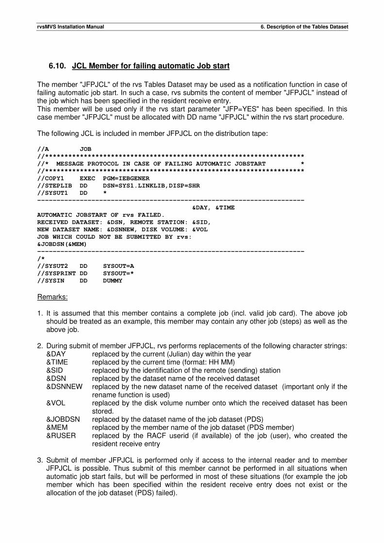
rvsMVS Installation Manual 6. Description of the Tables Dataset
6.10. JCL Member for failing automatic Job start
The member "JFPJCL" of the rvs Tables Dataset may be used as a notification function in case of failing automatic job start. In such a case, rvs submits the content of member "JFPJCL" instead of the job which has been specified in the resident receive entry. This member will be used only if the rvs start parameter "JFP=YES" has been specified. In this case member "JFPJCL" must be allocated with DD name "JFPJCL" within the rvs start procedure. The following JCL is included in member JFPJCL on the distribution tape: //A JOB
//*******************************************************************
//* MESSAGE PROTOCOL IN CASE OF FAILING AUTOMATIC JOBSTART *
//*******************************************************************
//COPY1 EXEC PGM=IEBGENER
//STEPLIB DD DSN=SYS1.LINKLIB,DISP=SHR
//SYSUT1 DD *
---------------------------------------------------------------------
&DAY, &TIME
AUTOMATIC JOBSTART OF rvs FAILED.
RECEIVED DATASET: &DSN, REMOTE STATION: &SID,
NEW DATASET NAME: &DSNNEW, DISK VOLUME: &VOL
JOB WHICH COULD NOT BE SUBMITTED BY rvs:
&JOBDSN(&MEM)
---------------------------------------------------------------------
/*
//SYSUT2 DD SYSOUT=A
//SYSPRINT DD SYSOUT=*
//SYSIN DD DUMMY
Remarks: 1. It is assumed that this member contains a complete job (incl. valid job card). The above job
should be treated as an example, this member may contain any other job (steps) as well as the above job.
2. During submit of member JFPJCL, rvs performs replacements of the following character strings:
&DAY replaced by the current (Julian) day within the year &TIME replaced by the current time (format: HH MM) &SID replaced by the identification of the remote (sending) station &DSN replaced by the dataset name of the received dataset &DSNNEW replaced by the new dataset name of the received dataset (important only if the
rename function is used) &VOL replaced by the disk volume number onto which the received dataset has been
stored. &JOBDSN replaced by the dataset name of the job dataset (PDS) &MEM replaced by the member name of the job dataset (PDS member) &RUSER replaced by the RACF userid (if available) of the job (user), who created the
resident receive entry 3. Submit of member JFPJCL is performed only if access to the internal reader and to member
JFPJCL is possible. Thus submit of this member cannot be performed in all situations when automatic job start fails, but will be performed in most of these situations (for example the job member which has been specified within the resident receive entry does not exist or the allocation of the job dataset (PDS) failed).

rvsMVS Installation Manual 6. Description of the Tables Dataset
4. It is not possible to display the reason for the failing automatic job start within this function (processing of the rvs start parameter "JFP=YES"). The reason for failing automatic job start must be obtained from the rvs error message which is displayed on console (hardcopy) at the time when the job start failed.
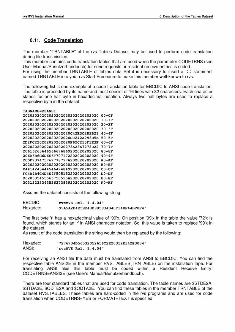
rvsMVS Installation Manual 6. Description of the Tables Dataset
6.11. Code Translation
The member "TRNTABLE" of the rvs Tables Dataset may be used to perform code translation during file transmission. This member contains code translation tables that are used when the parameter CODETRNS (see User Manual/Benutzerhandbuch) for send requests or resident receive entries is coded. For using the member TRNTABLE of tables data Set it is necessary to insert a DD statement named TRNTABLE into your rvs Start Procedure to make this member well-known to rvs. The following list is one example of a code translation table for EBCDIC to ANSI code translation. The table is preceded by its name and must consist of 16 lines with 32 characters. Each character stands for one half byte in hexadecimal notation. Always two half bytes are used to replace a respective byte in the dataset: TABNAME=E2ANSI
20202020202020202020202020202020 00-0F
20202020202020202020202020202020 10-1F
20202020202020202020202020202020 20-2F
20202020202020202020202020202020 30-3F
20202020202020202020C42E3C282B21 40-4F
26202020202020202020DC242A293B5E 50-5F
2D2FC220202020202020F62C255F3E3F 60-6F
202020202020202020273A23A7273D22 70-7F
20616263646566676869202020202020 80-8F
206A6B6C6D6E6F707172202020202020 90-9F
20DF737475767778797A202020202020 A0-AF
20202020202020202020202020202020 B0-BF
E4414243444546474849202020202020 C0-CF
FC4A4B4C4D4E4F505152202020202020 D0-DF
D620535455565758595A202020202020 E0-EF
30313233343536373839202020202020 F0-FF
Assume the dataset consists of the following string: EBCDIC: "rvsMVS Rel. 1.4.04"
Hexadec: "99A5A2D4E5E240D985934B40F14BF44BF0F4" The first byte 'r' has a hexadecimal value of '99'x. On position '99'x in the table the value '72'x is found, which stands for an 'r' in ANSI character notation. So, this value is taken to replace '99'x in the dataset. As result of the code translation the string would then be replaced by the following: Hexadec: "7276734D56532052656C2E20312E342E3034“ ANSI: "rvsMVS Rel. 1.4.04" For receiving an ANSI file the data must be translated from ANSI to EBCDIC. You can find the respective table ANSI2E in the member RVS.TABLES(TRNTABLE) on the installation tape. For translating ANSI files this table must be coded within a Resident Receive Entry: CODETRNS=ANSI2E (see User's Manual/Benutzerhandbuch). There are four standard tables that are used for code translation. The table names are $STDE2A, $STDA2E, $ODTE2A and $ODTA2E. You can find these tables in the member TRNTABLE of the dataset RVS.TABLES. These tables are hard-coded in the rvs programs and are used for code translation when CODETRNS=YES or FORMAT=TEXT is specified:
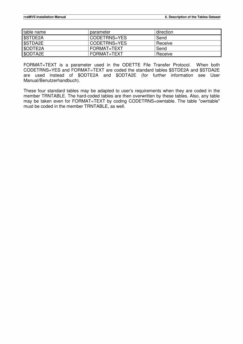
rvsMVS Installation Manual 6. Description of the Tables Dataset
table name parameter direction
$STDE2A CODETRNS=YES Send $STDA2E CODETRNS=YES Receive $ODTE2A FORMAT=TEXT Send $ODTA2E FORMAT=TEXT Receive
FORMAT=TEXT is a parameter used in the ODETTE File Transfer Protocol. When both CODETRNS=YES and FORMAT=TEXT are coded the standard tables $STDE2A and $STDA2E are used instead of $ODTE2A and $ODTA2E (for further information see User Manual/Benutzerhandbuch). These four standard tables may be adapted to user's requirements when they are coded in the member TRNTABLE. The hard-coded tables are then overwritten by these tables. Also, any table may be taken even for FORMAT=TEXT by coding CODETRNS=owntable. The table "owntable" must be coded in the member TRNTABLE, as well.

rvsMVS Installation Manual 6. Description of the Tables Dataset
This page will be intentionally empty.
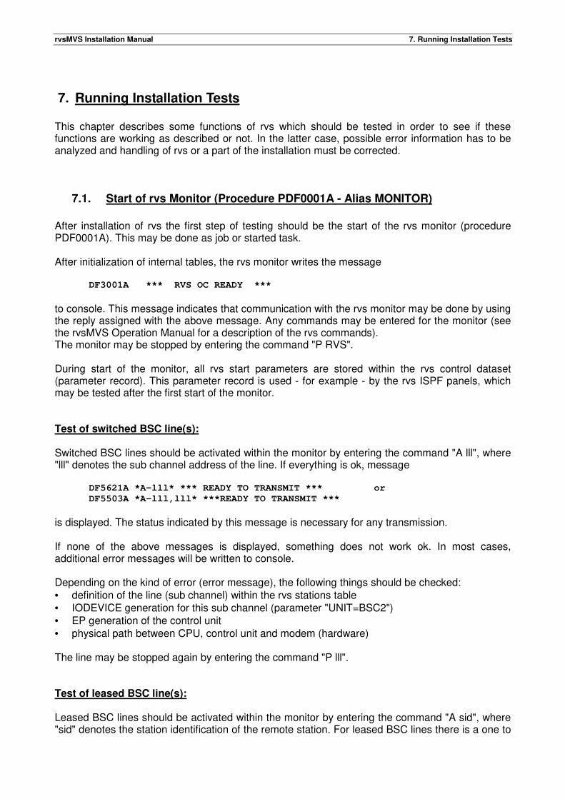
rvsMVS Installation Manual 7. Running Installation Tests
7. Running Installation Tests This chapter describes some functions of rvs which should be tested in order to see if these functions are working as described or not. In the latter case, possible error information has to be analyzed and handling of rvs or a part of the installation must be corrected.
7.1. Start of rvs Monitor (Procedure PDF0001A - Alias MONITOR)
After installation of rvs the first step of testing should be the start of the rvs monitor (procedure PDF0001A). This may be done as job or started task. After initialization of internal tables, the rvs monitor writes the message DF3001A *** RVS OC READY ***
to console. This message indicates that communication with the rvs monitor may be done by using the reply assigned with the above message. Any commands may be entered for the monitor (see the rvsMVS Operation Manual for a description of the rvs commands). The monitor may be stopped by entering the command "P RVS". During start of the monitor, all rvs start parameters are stored within the rvs control dataset (parameter record). This parameter record is used - for example - by the rvs ISPF panels, which may be tested after the first start of the monitor. Test of switched BSC line(s): Switched BSC lines should be activated within the monitor by entering the command "A lll", where "lll" denotes the sub channel address of the line. If everything is ok, message DF5621A *A-lll* *** READY TO TRANSMIT *** or
DF5503A *A-lll,lll* ***READY TO TRANSMIT ***
is displayed. The status indicated by this message is necessary for any transmission. If none of the above messages is displayed, something does not work ok. In most cases, additional error messages will be written to console. Depending on the kind of error (error message), the following things should be checked: • definition of the line (sub channel) within the rvs stations table • IODEVICE generation for this sub channel (parameter "UNIT=BSC2") • EP generation of the control unit • physical path between CPU, control unit and modem (hardware) The line may be stopped again by entering the command "P lll". Test of leased BSC line(s): Leased BSC lines should be activated within the monitor by entering the command "A sid", where "sid" denotes the station identification of the remote station. For leased BSC lines there is a one to
rvsMVS Installation Manual 7. Running Installation Tests
one relationship between station identification and sub channel address for the associated line. After activation, the command "DS" should be used to obtain the status of the line. If activation is ok, one of the following messages will be displayed: DF3019I *A-sid* LINE lll IS WAITING FOR WORK or
DF3020I *A-sid,lll* REMOTE STATION IS NOT READY
If none of the above messages is displayed, something does not work ok. In most cases, additional error messages will be written to console. Depending on the kind of error (error message), the following things should be checked: • definition of the line (sub channel) within the rvs stations table • IODEVICE generation for this sub channel (parameter "UNIT=BSC1") • EP generation of the control unit • physical path between CPU, control unit and modem (hardware) The line may be stopped again by entering the command "P sid". Test of SNA connections: Before SNA sessions can be activated between local and remote installation, the rvs VTAM subtask must be started. This must be done by entering the command "A RVSVTAM". If activation was successful, message DF9005I *** RVS VTAM CONTROL TASK READY ***
is displayed. If activation is not successful, error messages will be displayed which indicate the kind of error. After activation of the rvs VTAM subtask, sessions to the remote station may be activated by entering the command "A sid". In this case, rvs tries to activate all sessions which are defined (stations table, session profile) for the remote installation. Message DF9902I *F-sid nm* SESSION ESTABLISHED FOR LU luname CID=address
indicates successful activation of one session to the remote station. In case of error conditions error messages will be displayed instead of the above message. Activated sessions may be stopped by entering the command "P sid". Test of X25 connections: Before X25 sessions can be activated between local and remote installation, the rvs X25 control task must be started. This must be done by entering the command "A RVSX25". If activation was successful, message DF9501I RVS/X.25 CTCP INITIALIZATION COMPLETE
is displayed. If activation is not successful, error messages will be displayed which indicate the kind of error. After activation of the rvs X25 control task, sessions to the remote station may be activated by entering the command "A sid". In this case, rvs tries to establish a switched virtual circuit (SVC) to the remote installation. Message
rvsMVS Installation Manual 7. Running Installation Tests
DF9401I *F-sid* ODETTE TASK STARTED TYPE=type
indicates successful activation of the SVC to the remote station. In case of error conditions error messages will be displayed instead of the above message. The SVC will be stopped automatically if there is nothing (more) to send (or receive) or if any error occurs. X25 loop test In order to verify your VTAM and NPSI generation you can start a simple loop test. For the loop test you don't need a partner station, because you call your own station. The call packet is set up on one of your SVCs, routed back by the first switching node of the X.25 network and received by a second SVC of your multichannel link. This implies that the multichannel link must have at least 2 SVC's and the rvs start parameter MAXSVC must specify a value of at least 2 SVC's. The station you call is to be defined within STATIONS TABLE in the usual way (see chapter 6, X25-entry). The values of SID, ODETID and X25NUM must be identical to the values you coded for the local station (member CNTL of the TABLES dataset). Furthermore SENDPW and RECVPW must be equal and the parameter DIRECTN=B must be active (specified or by default) for both station definitions. If you want to send data, you have to take care of different names on sender and receiver side ---> work with the rename function when queuing the dataset. Test of TCP connections: Before TCP/IP sessions can be activated between local and remote installation, the rvs TCP/IP control task must be started. This must be done by entering the command "A RVSTCP". If activation was successful, message DF8301I TCP/IP INITIALIZATION COMPLETE, LV=...
is displayed. If activation is not successful, error messages will be displayed which indicate the kind of error. After activation of the TCP/IP control task, sessions to the remote station may be activated by entering the command "A sid". In this case, rvs tries to establish a connection to the remote installation. Message DF8301I *F-sid* CONNECT COMPLETE, S=...
indicates successful activation of a TCP/IP connection to the remote station. In case of error conditions error messages will be displayed instead of the above message. The TCP/IP connection will be closed automatically if there is nothing (more) to send (or receive) or if any error occurs. TCP/IP loop test For the loop test you don't need a partner station, because you connect with your own station. For the loop test, a station entry must be defined in the following way:
rvsMVS Installation Manual 7. Running Installation Tests
The station you call is to be defined within STATIONS TABLE in the usual way (see chapter 6, TCP-entry). The values of SID, ODETID and TCPPORT must be identical to the values you coded for the local station (member CNTL of the TABLES dataset). The TCPIPADR-parameter of the stations definition must specify the IP address of the local installation Furthermore SENDPW and RECVPW must be equal and the parameter DIRECTN=B must be active (specified or by default) for both station definitions. If you want to send data, you have to take care of different names on sender and receiver side ---> work with the rename function when queuing the dataset.
7.2. Transmission of Datasets
The following steps must be performed for transmission tests (send, receive): • creation of a dataset to be sent (size of about 50 records) • queuing this dataset for transmission to the remote installation (this may be done with program
DF080A00 or with the rvs ISPF panels (see rvsMVS User Manual (Benutzerhandbuch) for more details.
• creation of "resident receive entries" for the datasets to be received (necessary only if special functions like automatic job start shall be tested)
• start of the rvs monitor and the transmission component • activation of BSC line(s) or activation of SNA session(s) If a SNA connection is established (send session(s), receive session(s)), all transmissions of datasets which are queued for sending will be performed automatically by the rvs monitor, indicated by several messages. If a leased BSC line is used for transmission, all transmissions of datasets which are queued for sending will be performed automatically by the rvs monitor after activation of the line within rvs and depending on the situation within the remote installation. If a switched BSC line is used for transmission, after activation of the line within rvs the line connection to the remote installation must be established (dialing) and - for telephone lines - the modems on both sides must be switched from voice to data. Both, dialing and modem switching may be done manually or automatically, depending on the hardware capabilities and the definitions within rvs (autodial function). If the line connection is established and the identification between local and remote station is complete, the datasets queued for sending will be transmitted. Remarks: If transmissions on BSC lines are not executed, an rvs trace (and in special cases a GTF trace (CCW trace)) should be activated for the used line in order to obtain more information about the failing transmission. This information together with the rvs messages of this situation should be discussed with the software producer. The following station identification is used for VW AG: R11 - Volkswagen AG Wolfsburg If transmission tests are planned with VW AG Wolfsburg, the following names of datasets are used for tests: „LOOPTEST“
When a dataset with this name is sent to station R11 (regardless of its content or file format), it will automatically be sent back to its original sender.
rvsMVS Installation Manual 8. Special Functions (Procedures)
8. Special Functions (Procedures)
8.1. Using BSC Line(s) as Backup for SNA
This section contains a description of all definitions and actions, which are necessary if BSC line(s) shall be used as backup for a SNA connection between two rvsMVS installations. 1. rvs Station Table: Both Stations Tables must contain entries for • the SNA connection to the remote installation (parameter "ACME=VTAM") • the (backup) connection to the remote installation (parameters "ACME=BTAM", "SNCL=lll") • the line(s) (sub channel(s)) to be used (Parameter "LINE=nnn) The entry for backup connection (parameter "ACME=BTAM") must be located within the stations table before the entry defining the SNA connection. One of both station tables must assign a program profile defined as "master" to the entries for backup connection and line (sub channel) definition. The other station table must assign a program profile defined as "slave" to the entries for backup connection and line (sub channel) definition. Remark: A program profile for a line entry may be changed without stopping rvs if the following commands are entered: P lll stopping the line (sub channel) (if active) F sid,PP=ppp changing the program profile for the line A lll activating the line (sub channel) 2. Restrictions for backup operation: rvs is not designed to support transmissions between two installations using BSC and SNA at the same time. A restart of an abended transmission is possible only if the restart is done with the same access method (BTAM or VTAM) which was used when the transmission abended. Therefore the command "S sid,,R" must be entered on both sides to suppress any restart if the access method for transmissions between both installations is changed (from BTAM to VTAM or from VTAM to BTAM).
8.2. rvs Trace
rvs allows starting a line trace (BSC lines), a session trace (SNA sessions, LU62 sessions, TCP sessions, FTP transmissions or X25 sessions) or an internal trace in order to • get further information in fault situations
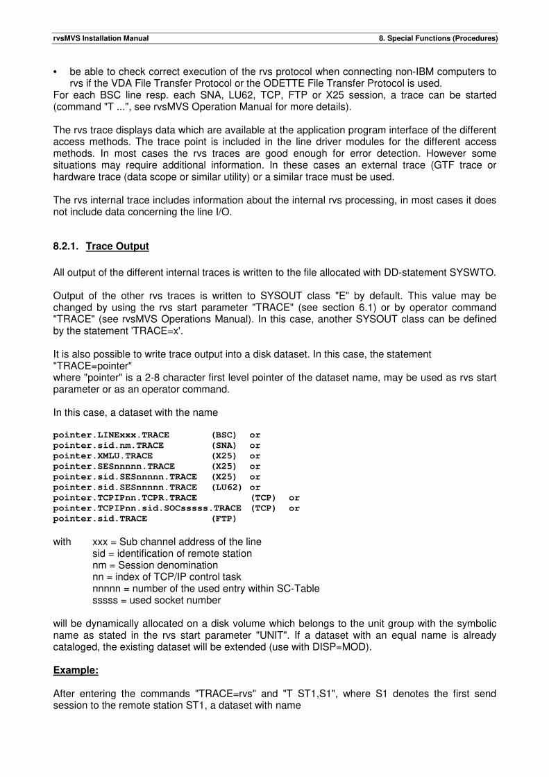
rvsMVS Installation Manual 8. Special Functions (Procedures)
• be able to check correct execution of the rvs protocol when connecting non-IBM computers to rvs if the VDA File Transfer Protocol or the ODETTE File Transfer Protocol is used.
For each BSC line resp. each SNA, LU62, TCP, FTP or X25 session, a trace can be started (command "T ...", see rvsMVS Operation Manual for more details). The rvs trace displays data which are available at the application program interface of the different access methods. The trace point is included in the line driver modules for the different access methods. In most cases the rvs traces are good enough for error detection. However some situations may require additional information. In these cases an external trace (GTF trace or hardware trace (data scope or similar utility) or a similar trace must be used. The rvs internal trace includes information about the internal rvs processing, in most cases it does not include data concerning the line I/O.
8.2.1. Trace Output
All output of the different internal traces is written to the file allocated with DD-statement SYSWTO. Output of the other rvs traces is written to SYSOUT class "E" by default. This value may be changed by using the rvs start parameter "TRACE" (see section 6.1) or by operator command "TRACE" (see rvsMVS Operations Manual). In this case, another SYSOUT class can be defined by the statement 'TRACE=x'. It is also possible to write trace output into a disk dataset. In this case, the statement "TRACE=pointer" where "pointer" is a 2-8 character first level pointer of the dataset name, may be used as rvs start parameter or as an operator command. In this case, a dataset with the name pointer.LINExxx.TRACE (BSC) or
pointer.sid.nm.TRACE (SNA) or
pointer.XMLU.TRACE (X25) or
pointer.SESnnnnn.TRACE (X25) or
pointer.sid.SESnnnnn.TRACE (X25) or
pointer.sid.SESnnnnn.TRACE (LU62) or
pointer.TCPIPnn.TCPR.TRACE (TCP) or
pointer.TCPIPnn.sid.SOCsssss.TRACE (TCP) or
pointer.sid.TRACE (FTP)
with xxx = Sub channel address of the line sid = identification of remote station nm = Session denomination nn = index of TCP/IP control task nnnnn = number of the used entry within SC-Table sssss = used socket number will be dynamically allocated on a disk volume which belongs to the unit group with the symbolic name as stated in the rvs start parameter "UNIT". If a dataset with an equal name is already cataloged, the existing dataset will be extended (use with DISP=MOD). Example: After entering the commands "TRACE=rvs" and "T ST1,S1", where S1 denotes the first send session to the remote station ST1, a dataset with name
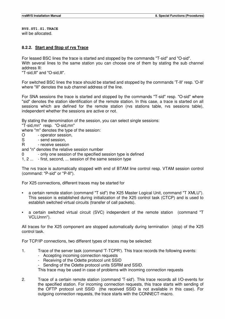
rvsMVS Installation Manual 8. Special Functions (Procedures)
RVS.ST1.S1.TRACE
will be allocated.
8.2.2. Start and Stop of rvs Trace
For leased BSC lines the trace is started and stopped by the commands "T-sid" and "O-sid". With several lines to the same station you can choose one of them by stating the sub channel address lll: "T-sid,lll" and "O-sid,lll". For switched BSC lines the trace should be started and stopped by the commands 'T-lll' resp. 'O-lll' where "lll" denotes the sub channel address of the line. For SNA sessions the trace is started and stopped by the commands "T-sid" resp. "O-sid" where "sid" denotes the station identification of the remote station. In this case, a trace is started on all sessions which are defined for the remote station (rvs stations table, rvs sessions table), independent whether the sessions are active or not. By stating the denomination of the session, you can select single sessions: "T-sid,mn" resp. "O-sid,mn" where "m" denotes the type of the session: O - operator session, S - send session, R - receive session and "n" denotes the relative session number 0 - only one session of the specified session type is defined 1, 2 ... - first, second, ... session of the same session type The rvs trace is automatically stopped with end of BTAM line control resp. VTAM session control (command: "P-sid" or "P-lll"). For X25 connections, different traces may be started for • a certain remote station (command "T sid") the X25 Master Logical Unit, command "T XMLU").
This session is established during initialization of the X25 control task (CTCP) and is used to establish switched virtual circuits (transfer of call packets).
• a certain switched virtual circuit (SVC) independent of the remote station (command "T
VCLUnnn"). All traces for the X25 component are stopped automatically during termination (stop) of the X25 control task. For TCP/IP connections, two different types of traces may be selected: 1. Trace of the server task (command 'T-TCPR'). This trace records the following events:
- Accepting incoming connection requests - Receiving of the Odette protocol unit SSID - Sending of the Odette protocol units SSRM and SSID. This trace may be used in case of problems with incoming connection requests
2. Trace of a certain remote station (command 'T-sid'). This trace records all I/O-events for the specified station. For incoming connection requests, this trace starts with sending of the OFTP protocol unit SSID (the received SSID is not available in this case). For outgoing connection requests, the trace starts with the CONNECT-macro.
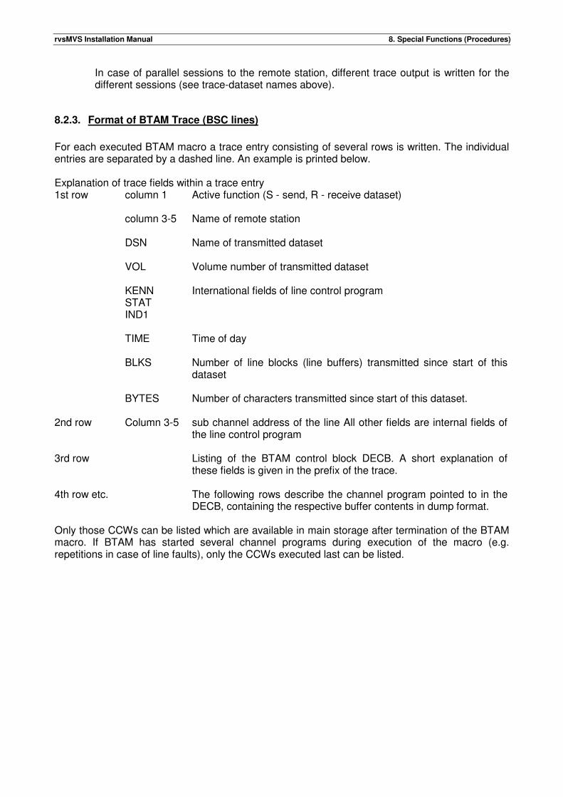
rvsMVS Installation Manual 8. Special Functions (Procedures)
In case of parallel sessions to the remote station, different trace output is written for the different sessions (see trace-dataset names above).
8.2.3. Format of BTAM Trace (BSC lines)
For each executed BTAM macro a trace entry consisting of several rows is written. The individual entries are separated by a dashed line. An example is printed below. Explanation of trace fields within a trace entry 1st row column 1 Active function (S - send, R - receive dataset)
column 3-5 Name of remote station
DSN Name of transmitted dataset
VOL Volume number of transmitted dataset
KENN
STAT IND1
International fields of line control program
TIME Time of day
BLKS Number of line blocks (line buffers) transmitted since start of this dataset
BYTES Number of characters transmitted since start of this dataset.
2nd row Column 3-5 sub channel address of the line All other fields are internal fields of the line control program
3rd row Listing of the BTAM control block DECB. A short explanation of these fields is given in the prefix of the trace.
4th row etc. The following rows describe the channel program pointed to in the DECB, containing the respective buffer contents in dump format.
Only those CCWs can be listed which are available in main storage after termination of the BTAM macro. If BTAM has started several channel programs during execution of the macro (e.g. repetitions in case of line faults), only the CCWs executed last can be listed.
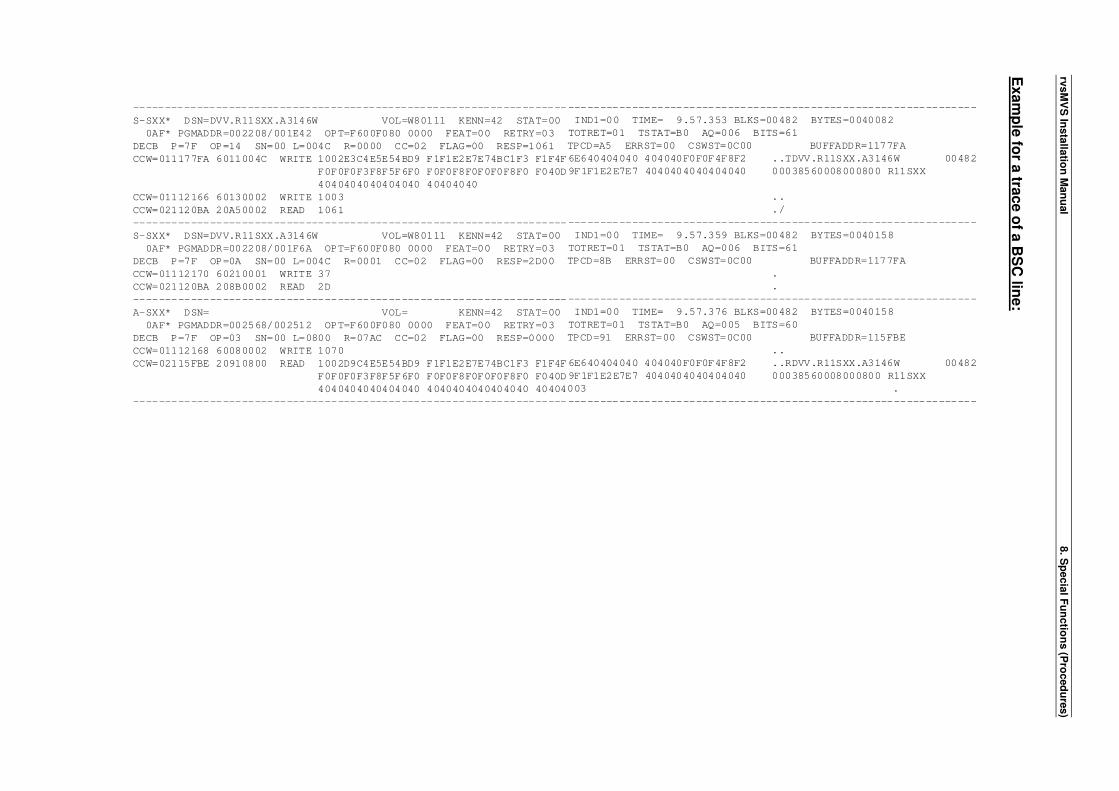
rvsM
VS
Insta
llatio
n M
an
ual
8. S
pecia
l Fu
nctio
ns (P
roced
ure
s)
Exam
ple
for a
trace o
f a B
SC
line:
--------------------------------------------------------------------
S-SXX* DSN=DVV.R11SXX.A3146W VOL=W80111 KENN=42 STAT=00
0AF* PGMADDR=002208/001E42 OPT=F600F080 0000 FEAT=00 RETRY=03
DECB P=7F OP=14 SN=00 L=004C R=0000 CC=02 FLAG=00 RESP=1061
CCW=011177FA 6011004C WRITE 1002E3C4E5E54BD9 F1F1E2E7E74BC1F3 F1F4F
F0F0F0F3F8F5F6F0 F0F0F8F0F0F0F8F0 F040D
4040404040404040 40404040
CCW=01112166 60130002 WRITE 1003
CCW=021120BA 20A50002 READ 1061
--------------------------------------------------------------------
S-SXX* DSN=DVV.R11SXX.A3146W VOL=W80111 KENN=42 STAT=00
0AF* PGMADDR=002208/001F6A OPT=F600F080 0000 FEAT=00 RETRY=03
DECB P=7F OP=0A SN=00 L=004C R=0001 CC=02 FLAG=00 RESP=2D00
CCW=01112170 60210001 WRITE 37
CCW=021120BA 208B0002 READ 2D
--------------------------------------------------------------------
A-SXX* DSN= VOL= KENN=42 STAT=00
0AF* PGMADDR=002568/002512 OPT=F600F080 0000 FEAT=00 RETRY=03
DECB P=7F OP=03 SN=00 L=0800 R=07AC CC=02 FLAG=00 RESP=0000
CCW=01112168 60080002 WRITE 1070
CCW=02115FBE 20910800 READ 1002D9C4E5E54BD9 F1F1E2E7E74BC1F3 F1F4F
F0F0F0F3F8F5F6F0 F0F0F8F0F0F0F8F0 F040D
4040404040404040 4040404040404040 40404
--------------------------------------------------------------------
----------------------------------------------------------------
IND1=00 TIME= 9.57.353 BLKS=00482 BYTES=0040082
TOTRET=01 TSTAT=B0 AQ=006 BITS=61
TPCD=A5 ERRST=00 CSWST=0C00 BUFFADDR=1177FA
6E640404040 404040F0F0F4F8F2 ..TDVV.R11SXX.A3146W 00482
9F1F1E2E7E7 4040404040404040 00038560008000800 R11SXX
..
./
----------------------------------------------------------------
IND1=00 TIME= 9.57.359 BLKS=00482 BYTES=0040158
TOTRET=01 TSTAT=B0 AQ=006 BITS=61
TPCD=8B ERRST=00 CSWST=0C00 BUFFADDR=1177FA
.
.
----------------------------------------------------------------
IND1=00 TIME= 9.57.376 BLKS=00482 BYTES=0040158
TOTRET=01 TSTAT=B0 AQ=005 BITS=60
TPCD=91 ERRST=00 CSWST=0C00 BUFFADDR=115FBE
..
6E640404040 404040F0F0F4F8F2 ..RDVV.R11SXX.A3146W 00482
9F1F1E2E7E7 4040404040404040 00038560008000800 R11SXX
003 .
----------------------------------------------------------------
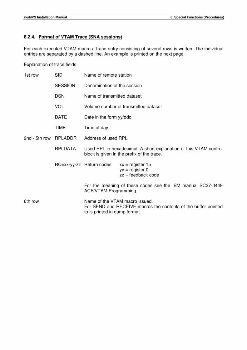
rvsMVS Installation Manual 8. Special Functions (Procedures)
8.2.4. Format of VTAM Trace (SNA sessions)
For each executed VTAM macro a trace entry consisting of several rows is written. The individual entries are separated by a dashed line. An example is printed on the next page. Explanation of trace fields: 1st row SID Name of remote station
SESSION Denomination of the session
DSN Name of transmitted dataset
VOL Volume number of transmitted dataset
DATE Date in the form yy/ddd
TIME Time of day
2nd - 5th row RPLADDR Address of used RPL
RPLDATA Used RPL in hexadecimal. A short explanation of this VTAM control
block is given in the prefix of the trace.
RC=xx-yy-zz Return codes xx = register 15 yy = register 0 zz = feedback code For the meaning of these codes see the IBM manual SC27-0449 ACF/VTAM Programming.
6th row Name of the VTAM macro issued. For SEND and RECEIVE macros the contents of the buffer pointed to is printed in dump format.
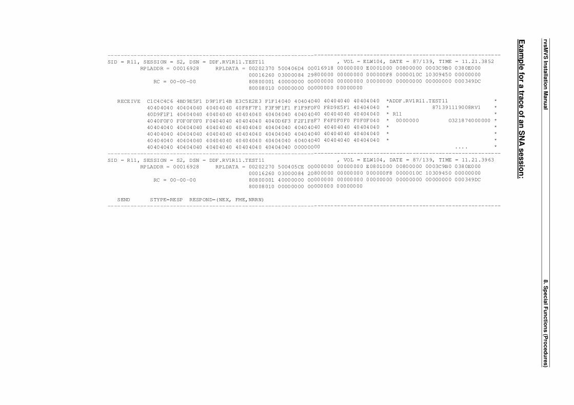
rvsM
VS
Insta
llatio
n M
an
ual
8. S
pecia
l Fu
nctio
ns (P
roced
ure
s)
Exam
ple
for a
trace o
f an
SN
A s
essio
n:
---------------------------------------------------------------
SID = R11, SESSION = S2, DSN = DDF.RV1R11.TEST11
RPLADDR = 00016928 RPLDATA = 00202370 500406D4 00
00016260 03000084 29
RC = 00-00-00 80800001 40000000 00
80008010 00000000 00
RECEIVE C1C4C4C6 4BD9E5F1 D9F1F14B E3C5E2E3 F1F14040 404040
40404040 40404040 40404040 40F8F7F1 F3F9F1F1 F1F9F0
40D9F1F1 40404040 40404040 40404040 40404040 404040
4040F0F0 F0F0F0F0 F0404040 40404040 4040D6F3 F2F1F8
40404040 40404040 40404040 40404040 40404040 404040
40404040 40404040 40404040 40404040 40404040 404040
40404040 40404040 40404040 40404040 40404040 404040
40404040 40404040 40404040 40404040 40404040 000000
---------------------------------------------------------------
SID = R11, SESSION = S2, DSN = DDF.RV1R11.TEST11
RPLADDR = 00016928 RPLDATA = 00202270 500405CE 00
00016260 03000084 20
RC = 00-00-00 80800001 40000000 00
80008010 00000000 00
SEND STYPE=RESP RESPOND=(NEX, FME,NRRN)
---------------------------------------------------------------
---------------------------------------------------------
, VOL = ELW104, DATE = 87/139, TIME = 11.21.3852
016918 00000000 E0001000 00800000 0003C9B0 0380E000
800000 00000000 000000F8 0000010C 10309450 00000000
000000 00000000 00000000 00000000 00000000 000349DC
000000 00000000
40 40404040 40404040 *ADDF.RV1R11.TEST11 *
F0 F8D9E5F1 40404040 * 871391119008RV1 *
40 40404040 40404040 * R11 *
F7 F4F0F0F0 F0F0F040 * 0000000 O321874000000 *
40 40404040 40404040 * *
40 40404040 40404040 * *
40 40404040 40404040 * *
00 .... *
---------------------------------------------------------
, VOL = ELW104, DATE = 87/139, TIME = 11.21.3963
000000 00000000 E0801000 00800000 0003C9B0 0380E000
800000 00000000 000000F8 0000010C 10309450 00000000
000000 00000000 00000000 00000000 00000000 000349DC
000000 00000000
---------------------------------------------------------
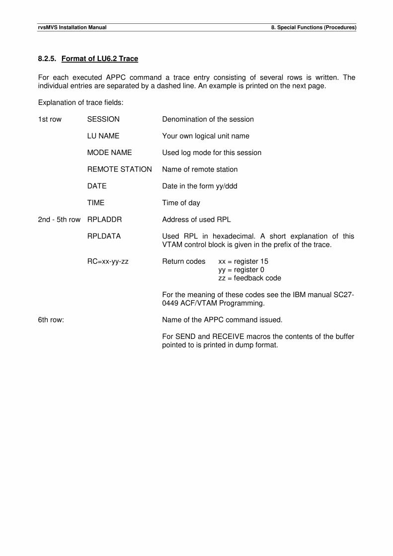
rvsMVS Installation Manual 8. Special Functions (Procedures)
8.2.5. Format of LU6.2 Trace
For each executed APPC command a trace entry consisting of several rows is written. The individual entries are separated by a dashed line. An example is printed on the next page. Explanation of trace fields: 1st row SESSION Denomination of the session
LU NAME Your own logical unit name
MODE NAME Used log mode for this session
REMOTE STATION Name of remote station
DATE Date in the form yy/ddd
TIME Time of day
2nd - 5th row RPLADDR Address of used RPL
RPLDATA Used RPL in hexadecimal. A short explanation of this
VTAM control block is given in the prefix of the trace.
RC=xx-yy-zz Return codes xx = register 15 yy = register 0 zz = feedback code For the meaning of these codes see the IBM manual SC27-0449 ACF/VTAM Programming.
6th row: Name of the APPC command issued. For SEND and RECEIVE macros the contents of the buffer pointed to is printed in dump format.
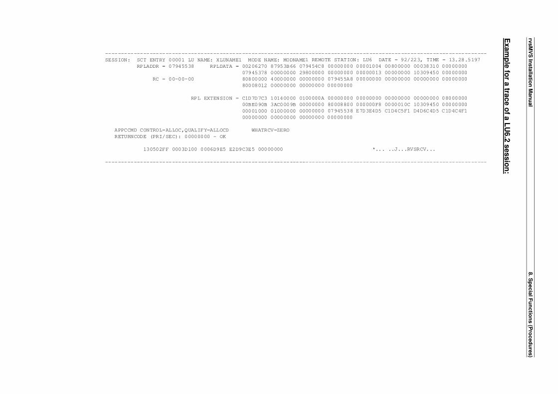
rvsM
VS
Insta
llatio
n M
an
ual
8. S
pecia
l Fu
nctio
ns (P
roced
ure
s)
Exam
ple
for a
trace o
f a L
U6.2
sessio
n:
---------------------------------------------------------------
SESSION: SCT ENTRY 00001 LU NAME: XLUNAME1 MODE NAME: MODNAME
RPLADDR = 07945538 RPLDATA = 00206270 87953B66 07
07945378 00000000 29
RC = 00-00-00 80800000 40000000 00
80008012 00000000 00
RPL EXTENSION = C1D7D7C3 10140000 01
00BE090B 3AC0009B 00
00001000 01000000 00
00000000 00000000 00
APPCCMD CONTROL=ALLOC,QUALIFY=ALLOCD WHATRCV=ZERO
RETURNCODE (PRI/SEC): 00000000 - OK
130502FF 0003D100 0006D9E5 E2D9C3E5 00000000
---------------------------------------------------------------
---------------------------------------------------------
1 REMOTE STATION: LU6 DATE = 92/223, TIME = 13.28.5197
9454C8 00000000 00001004 00800000 00038310 00000000
800000 00000000 00000013 00000000 10309450 00000000
000000 079455A8 00000000 00000000 00000000 00000000
000000 00000000
00000A 00000000 00000000 00000000 00000000 08000000
000000 80008800 000000F8 0000010C 10309450 00000000
000000 07945538 E7D3E4D5 C1D4C5F1 D4D6C4D5 C1D4C4F1
000000 00000000
*... ..J...RVSRCV...
---------------------------------------------------------
rvsMVS Installation Manual 8. Special Functions (Procedures)
8.2.6. Format of TCP/IP Trace
For each executed TCP/IP command (socket interface, assembler macro API) a formatted trace record consisting of several rows is written. Trace records are separated by a line of hyphens. An example is printed on the next page. Explanation of trace fields: 1st row SOCKET Local socket number
REMOTE ADDRESS IP-address of remote station
REMOTE PORT Remote port number. This port number varies for each
connection, it is different from that as specified within the rvs stations table for the remote station.
REMOTE STATION Rvs-ID of remote station
DATE Date in the form yy/ddd
TIME Time of day
2nd row REQUEST Type of request (CONNECT, ACCEPT, READ, WRITE, CANCEL, CLOSE)
Status of request (issued) or (complete). In most cases trace records are written only after completion of a request.
3rd row and following
Request-dependent data and parameter
For READ and WRITE, the received (sent) data are displayed in a dump format. ODETTE protocol records are additionally displayed formatted. For CONNECT (ACCEPT), parameters like local IP-address and local port number are displayed. For all completed requests the return / error code is displayed. The meaning of these codes depends on the executed request, for more details see IBM TCP/IP for MVS, Application Programming Interface, and Reference.
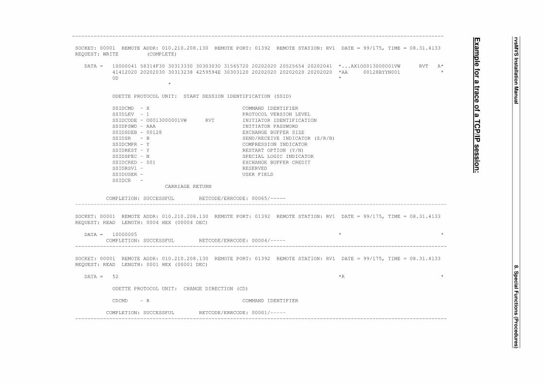
rvsM
VS
Insta
llatio
n M
an
ual
8. S
pecia
l Fu
nctio
ns (P
roced
ure
s)
Exam
ple
for a
trace o
f a T
CP
/IP s
essio
n:
------------------------------------------------------------------------------------------------------------------------
SOCKET: 00001 REMOTE ADDR: 010.210.208.130 REMOTE PORT: 01392 REMOTE STATION: RV1 DATE = 99/175, TIME = 08.31.4133
REQUEST: WRITE (COMPLETE)
DATA = 10000041 58314F30 30313330 30303030 31565720 20202020 20525654 20202041 *...AX1O0013000001VW RVT A*
41412020 20202030 30313238 4259594E 30303120 20202020 20202020 20202020 *AA 00128BYYN001 *
0D *
*
ODETTE PROTOCOL UNIT: START SESSION IDENTIFICATION (SSID)
SSIDCMD - X COMMAND IDENTIFIER
SSIDLEV - 1 PROTOCOL VERSION LEVEL
SSIDCODE - O0013000001VW RVT INITIATOR IDENTIFICATION
SSIDPSWD - AAA INITIATOR PASSWORD
SSIDSDEB - 00128 EXCHANGE BUFFER SIZE
SSIDSR - B SEND/RECEIVE INDICATOR (S/R/B)
SSIDCMPR - Y COMPRESSION INDICATOR
SSIDREST - Y RESTART OPTION (Y/N)
SSIDSPEC - N SPECIAL LOGIC INDICATOR
SSIDCRED - 001 EXCHANGE BUFFER CREDIT
SSIDRSV1 - RESERVED
SSIDUSER - USER FIELD
SSIDCR -
CARRIAGE RETURN
COMPLETION: SUCCESSFUL RETCODE/ERRCODE: 00065/-----
------------------------------------------------------------------------------------------------------------------------
SOCKET: 00001 REMOTE ADDR: 010.210.208.130 REMOTE PORT: 01392 REMOTE STATION: RV1 DATE = 99/175, TIME = 08.31.4133
REQUEST: READ LENGTH: 0004 HEX (00004 DEC)
DATA = 10000005 * *
COMPLETION: SUCCESSFUL RETCODE/ERRCODE: 00004/-----
------------------------------------------------------------------------------------------------------------------------
SOCKET: 00001 REMOTE ADDR: 010.210.208.130 REMOTE PORT: 01392 REMOTE STATION: RV1 DATE = 99/175, TIME = 08.31.4133
REQUEST: READ LENGTH: 0001 HEX (00001 DEC)
DATA = 52 *R *
ODETTE PROTOCOL UNIT: CHANGE DIRECTION (CD)
CDCMD - R COMMAND IDENTIFIER
COMPLETION: SUCCESSFUL RETCODE/ERRCODE: 00001/-----
------------------------------------------------------------------------------------------------------------------------
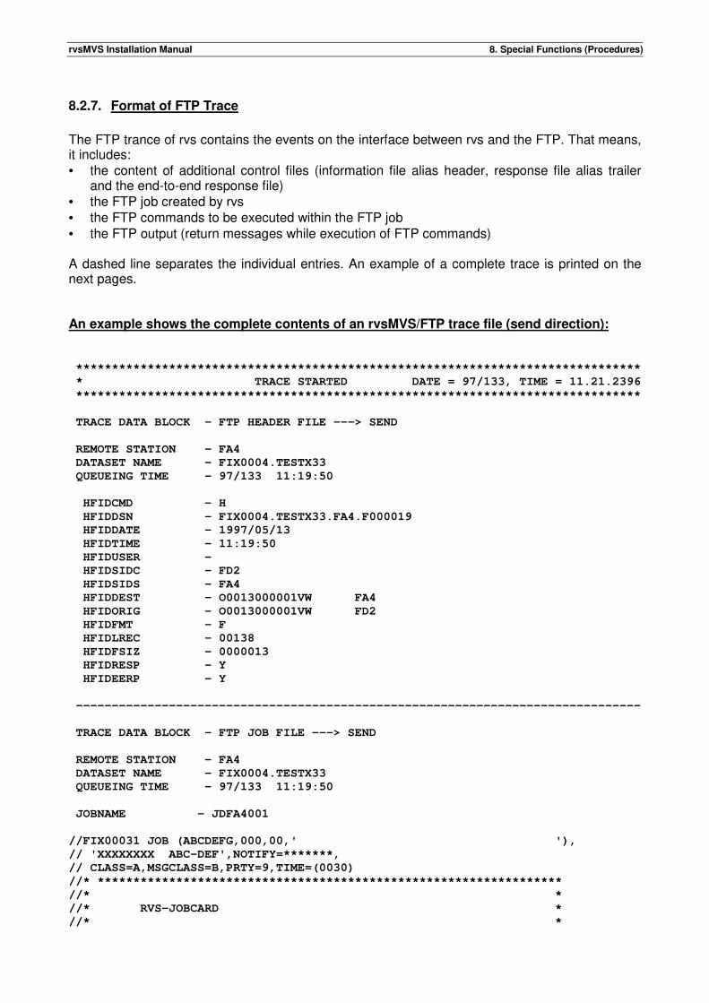
rvsMVS Installation Manual 8. Special Functions (Procedures)
8.2.7. Format of FTP Trace
The FTP trance of rvs contains the events on the interface between rvs and the FTP. That means, it includes: • the content of additional control files (information file alias header, response file alias trailer
and the end-to-end response file) • the FTP job created by rvs • the FTP commands to be executed within the FTP job • the FTP output (return messages while execution of FTP commands) A dashed line separates the individual entries. An example of a complete trace is printed on the next pages. An example shows the complete contents of an rvsMVS/FTP trace file (send direction): *******************************************************************************
* TRACE STARTED DATE = 97/133, TIME = 11.21.2396
*******************************************************************************
TRACE DATA BLOCK - FTP HEADER FILE ---> SEND
REMOTE STATION - FA4
DATASET NAME - FIX0004.TESTX33
QUEUEING TIME - 97/133 11:19:50
HFIDCMD - H
HFIDDSN - FIX0004.TESTX33.FA4.F000019
HFIDDATE - 1997/05/13
HFIDTIME - 11:19:50
HFIDUSER -
HFIDSIDC - FD2
HFIDSIDS - FA4
HFIDDEST - O0013000001VW FA4
HFIDORIG - O0013000001VW FD2
HFIDFMT - F
HFIDLREC - 00138
HFIDFSIZ - 0000013
HFIDRESP - Y
HFIDEERP - Y
-------------------------------------------------------------------------------
TRACE DATA BLOCK - FTP JOB FILE ---> SEND
REMOTE STATION - FA4
DATASET NAME - FIX0004.TESTX33
QUEUEING TIME - 97/133 11:19:50
JOBNAME - JDFA4001
//FIX00031 JOB (ABCDEFG,000,00,' '),
// 'XXXXXXXX ABC-DEF',NOTIFY=*******,
// CLASS=A,MSGCLASS=B,PRTY=9,TIME=(0030)
//* *****************************************************************
//* *
//* RVS-JOBCARD *
//* *
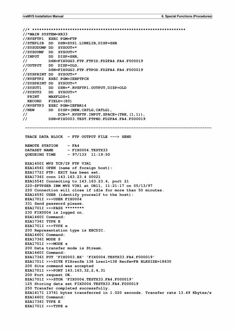
rvsMVS Installation Manual 8. Special Functions (Procedures)
//* *****************************************************************
//*MAIN SYSTEM=XR33
//RVSFTP1 EXEC PGM=FTP
//STEPLIB DD DSN=SYS1.LINKLIB,DISP=SHR
//SYSUDUMP DD SYSOUT=*
//SYSDUMP DD SYSOUT=*
//INPUT DD DISP=SHR,
// DSN=FIX0GG3.FTP.FTPID.FD2FA4.FA4.F000019
//OUTPUT DD DISP=OLD,
// DSN=FIX0GG3.FTP.FTPOD.FD2FA4.FA4.F000019
//SYSPRINT DD SYSOUT=*
//RVSFTP2 EXEC PGM=IEBPTPCH
//SYSPRINT DD SYSOUT=*
//SYSUT1 DD DSN=*.RVSFTP1.OUTPUT,DISP=OLD
//SYSUT2 DD SYSOUT=*
PRINT MAXFLDS=1
RECORD FIELD=(80)
//RVSFTP3 EXEC PGM=IEFBR14
//NEW DD DISP=(NEW,CATLG,CATLG),
// DCB=*.RVSFTP.INPUT,SPACE=(TRK,(1,1)),
// DSN=FIX0003.TEST.FTPND.FD2FA4.FA4.F000019
-------------------------------------------------------------------------------
TRACE DATA BLOCK - FTP OUTPUT FILE ---> SEND
REMOTE STATION - FA4
DATASET NAME - FIX0004.TESTX33
QUEUEING TIME - 97/133 11:19:50
EZA1450I MVS TCP/IP FTP V3R1
EZA1456I OPEN (name of foreign host):
EZA1772I FTP: EXIT has been set.
EZA1736I conn 143.163.23.4 00021
EZA1554I Connecting to 143.163.23.4, port 21
220-$FTPSER IBM MVS V3R1 at OR11, 11:21:17 on 05/13/97
220 Connection will close if idle for more than 50 minutes.
EZA1459I USER (identify yourself to the host):
EZA1701I >>>USER FIX0004
331 Send password please.
EZA1701I >>>PASS ********
230 FIX0004 is logged on.
EZA1460I Command:
EZA1736I TYPE E
EZA1701I >>>TYPE e
200 Representation type is EBCDIC.
EZA1460I Command:
EZA1736I MODE S
EZA1701I >>>MODE s
200 Data transfer mode is Stream.
EZA1460I Command:
EZA1736I PUT 'FIX0003.BX' 'FIX0004.TESTX33.FA4.F000019'
EZA1701I >>>SITE FIXrecfm 138 Lrecl=138 Recfm=FB BLKSIZE=18630
200 Site command was accepted
EZA1701I >>>PORT 143,163,32,2,4,31
200 Port request OK.
EZA1701I >>>STOR 'FIX0004.TESTX33.FA4.F000019'
125 Storing data set FIX0004.TESTX33.FA4.F000019
250 Transfer completed successfully.
EZA1617I 13761 bytes transferred in 1.020 seconds. Transfer rate 13.49 Kbytes/s
EZA1460I Command:
EZA1736I TYPE E
EZA1701I >>>TYPE e
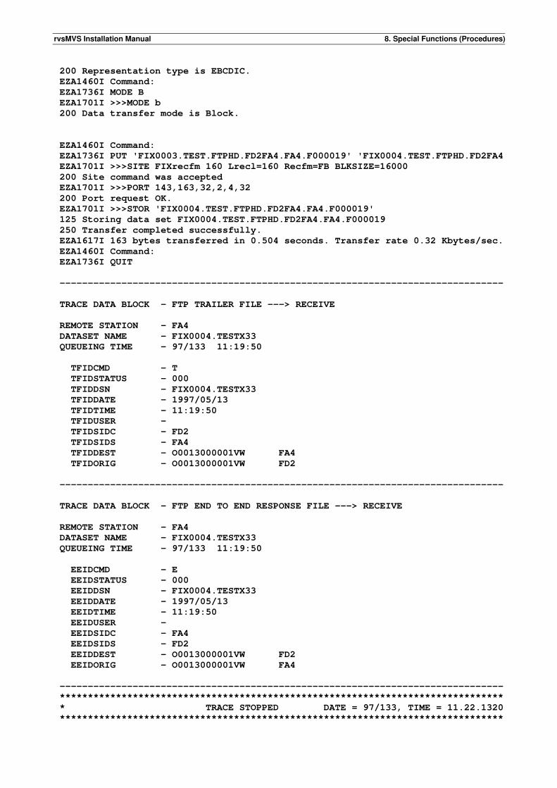
rvsMVS Installation Manual 8. Special Functions (Procedures)
200 Representation type is EBCDIC.
EZA1460I Command:
EZA1736I MODE B
EZA1701I >>>MODE b
200 Data transfer mode is Block.
EZA1460I Command:
EZA1736I PUT 'FIX0003.TEST.FTPHD.FD2FA4.FA4.F000019' 'FIX0004.TEST.FTPHD.FD2FA4
EZA1701I >>>SITE FIXrecfm 160 Lrecl=160 Recfm=FB BLKSIZE=16000
200 Site command was accepted
EZA1701I >>>PORT 143,163,32,2,4,32
200 Port request OK.
EZA1701I >>>STOR 'FIX0004.TEST.FTPHD.FD2FA4.FA4.F000019'
125 Storing data set FIX0004.TEST.FTPHD.FD2FA4.FA4.F000019
250 Transfer completed successfully.
EZA1617I 163 bytes transferred in 0.504 seconds. Transfer rate 0.32 Kbytes/sec.
EZA1460I Command:
EZA1736I QUIT
-------------------------------------------------------------------------------
TRACE DATA BLOCK - FTP TRAILER FILE ---> RECEIVE
REMOTE STATION - FA4
DATASET NAME - FIX0004.TESTX33
QUEUEING TIME - 97/133 11:19:50
TFIDCMD - T
TFIDSTATUS - 000
TFIDDSN - FIX0004.TESTX33
TFIDDATE - 1997/05/13
TFIDTIME - 11:19:50
TFIDUSER -
TFIDSIDC - FD2
TFIDSIDS - FA4
TFIDDEST - O0013000001VW FA4
TFIDORIG - O0013000001VW FD2
-------------------------------------------------------------------------------
TRACE DATA BLOCK - FTP END TO END RESPONSE FILE ---> RECEIVE
REMOTE STATION - FA4
DATASET NAME - FIX0004.TESTX33
QUEUEING TIME - 97/133 11:19:50
EEIDCMD - E
EEIDSTATUS - 000
EEIDDSN - FIX0004.TESTX33
EEIDDATE - 1997/05/13
EEIDTIME - 11:19:50
EEIDUSER -
EEIDSIDC - FA4
EEIDSIDS - FD2
EEIDDEST - O0013000001VW FD2
EEIDORIG - O0013000001VW FA4
-------------------------------------------------------------------------------
*******************************************************************************
* TRACE STOPPED DATE = 97/133, TIME = 11.22.1320
*******************************************************************************
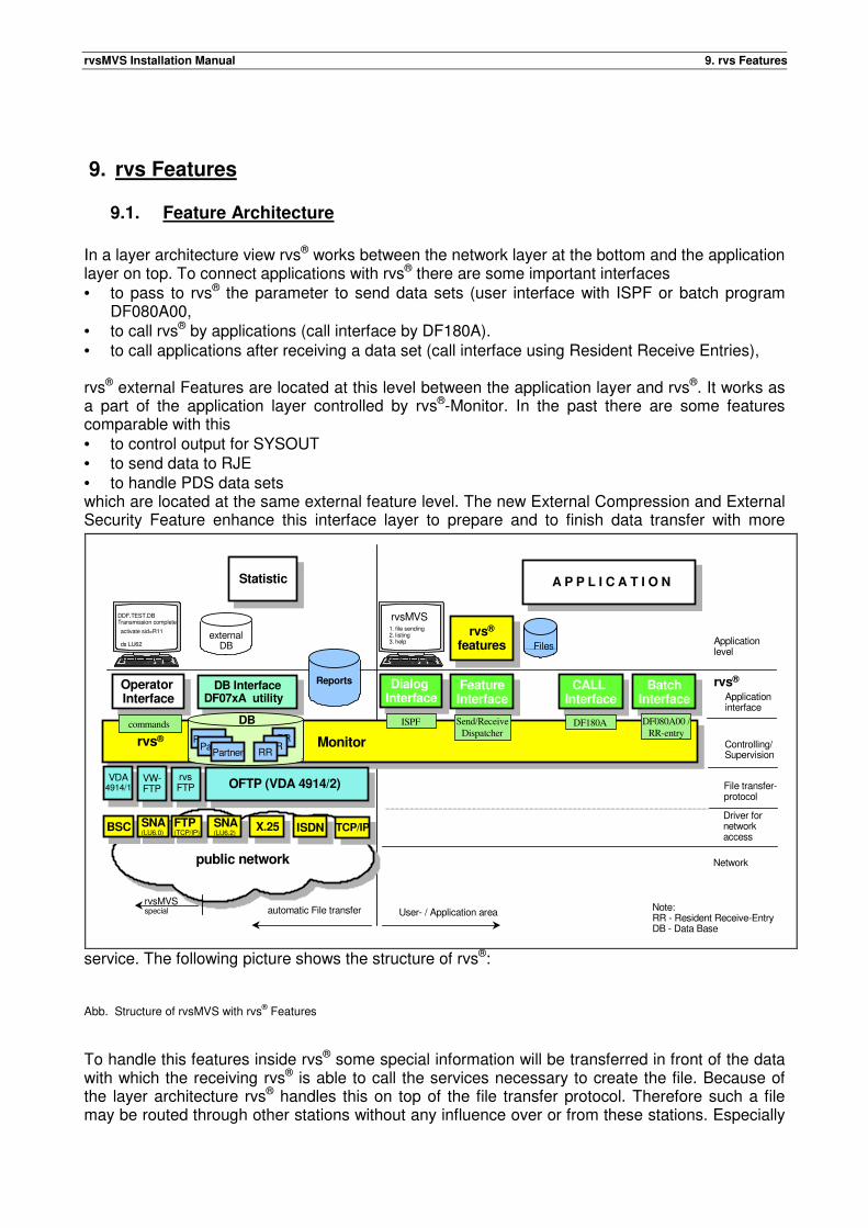
rvsMVS Installation Manual 9. rvs Features
9. rvs Features
9.1. Feature Architecture
In a layer architecture view rvs® works between the network layer at the bottom and the application layer on top. To connect applications with rvs® there are some important interfaces • to pass to rvs® the parameter to send data sets (user interface with ISPF or batch program
DF080A00, • to call rvs® by applications (call interface by DF180A). • to call applications after receiving a data set (call interface using Resident Receive Entries), rvs® external Features are located at this level between the application layer and rvs®. It works as a part of the application layer controlled by rvs®-Monitor. In the past there are some features comparable with this • to control output for SYSOUT • to send data to RJE • to handle PDS data sets which are located at the same external feature level. The new External Compression and External Security Feature enhance this interface layer to prepare and to finish data transfer with more
service. The following picture shows the structure of rvs®: Abb. Structure of rvsMVS with rvs® Features
To handle this features inside rvs® some special information will be transferred in front of the data with which the receiving rvs® is able to call the services necessary to create the file. Because of the layer architecture rvs® handles this on top of the file transfer protocol. Therefore such a file may be routed through other stations without any influence over or from these stations. Especially
DB InterfaceDF07xA utility
DB InterfaceDF07xA utility
Application level
Applicationinterface
Controlling/Supervision
File transfer-protocol
Driver fornetworkaccess
Operator Interface
Operator Interface
rvsMVS1. file sending2. listing3. help
activate sid=R11
ds LU62
DDF.TEST.DB Transmission complete
Dialog Interface
Dialog Interface
Files
A P P L I C A T I O N
public network
User- / Application areaautomatic File transfer Note:RR - Resident Receive-EntryDB - Data Base
rvs®
externalDB
rvsMVSspecial
BatchInterface
BatchInterface
CALL Interface
CALL Interface
Network
Reports
Statistic
DB
PartnerPartner
Partner
RRRR
RR
FeatureInterface
FeatureInterface
rvs®
features
X.25 ISDN TCP/IP
Monitor
commands Send/Receive
DispatcherDF180A DF080A00 /
RR-entry
ISPF
VDA4914/1
VW-FTP
rvsFTP OFTP (VDA 4914/2)
BSC SNA(LU6.0)
FTP(TCP/IP)
SNA(LU6.2)
rvs®
rvsMVS Installation Manual 9. rvs Features
in case of using OFTP as file transfer protocol the temporarily stored file isn't readable or process able without using special rvs® programs. Using OFTP rvs® transfers the following special control information from the sender to the receiver in case of • rvsMVS PDS File Transfer
Use of the complete user fields of SSID and SFID OFTP protocol record. These fields contain some flags leaded by an eye catcher: 'RF)' for initiator's outgoing protocol records and 'RF(' for incoming protocol records.
• Additionally rvsMVS uses a SFID extension (SFX1) to transfer partitioned data set information. • rvs internal compression (GZIP compatible)
Use of the complete user fields of SSID and SFID OFTP protocol record. These fields contain some flags leaded by an eye catcher ( RF) / RF( ).
• rvs external Security and Compression Feature Enhancement of the first data block with an rvs header (leaded by an eye catcher which consists of the string 'RVSF' with some hex characters, in total 10 characters). The length of the complete header is variable and depends on the used features.
9.2. Partioned Data Set (PDS) Transfer
The PDS-Transfer Feature of rvsMVS for OFTP stations uses the well known functions of PDS-Transfer from the rvsMVS SNA component.
• unload of a PDS during creation of Send Request • load of the PDS data set after receiving Whereas the header record of the SNA component transfers the data set attributes OFTP Protocol architecture gives no place for such information. Therefore the OFTP Protocol will be enhanced by • use of the SSID USER field • use of the SFID USER field • creation of the new protocol record SFX1. This enhancement will be used only if the station parameter TYPE=MVS is given. This means that in preparing the connection both partners have to make an agreement about the use of this feature and to inform rvsMVS about it by setting this parameter. It serves to avoid connections to a partner which needs a blank USER field. On the SSID level the USER field serves to inform the partner about the intended / available process of PDS Transfer. Therefore it contains the eye catcher described above 'RF)' or 'RF(' and the value '8' in the fourth byte. Additional combinations of this value with the values '4', '2' and '1' are possible and inform about more additional properties. On the SFID level the USER field serves to inform the partner about the use of the feature for this transmission. The construction of the field is equal to the SSID USER field. Value '8' (or a combination with it) shows the start of a PDS transfer. Instead of the first data buffer rvsMVS sends a special protocol record. This record contains all data set attributes of the unloaded PDS data set. The structure of this protocol record follows:
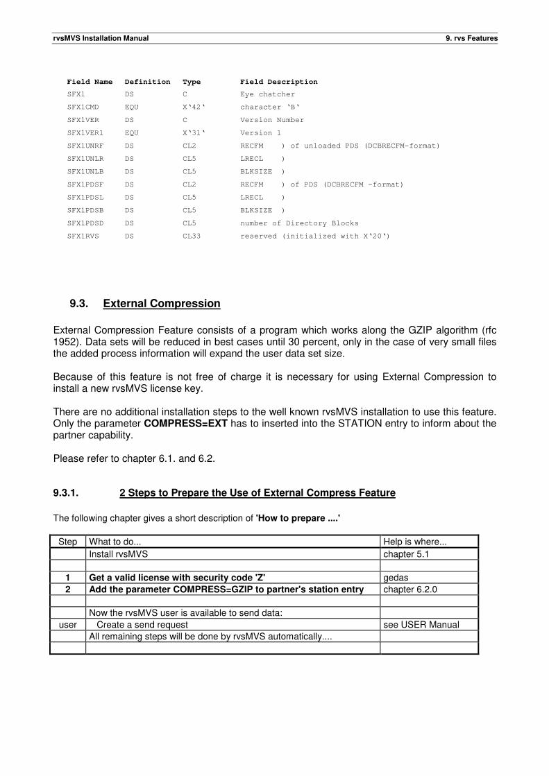
rvsMVS Installation Manual 9. rvs Features
9.3. External Compression
External Compression Feature consists of a program which works along the GZIP algorithm (rfc 1952). Data sets will be reduced in best cases until 30 percent, only in the case of very small files the added process information will expand the user data set size. Because of this feature is not free of charge it is necessary for using External Compression to install a new rvsMVS license key. There are no additional installation steps to the well known rvsMVS installation to use this feature. Only the parameter COMPRESS=EXT has to inserted into the STATION entry to inform about the partner capability. Please refer to chapter 6.1. and 6.2.
9.3.1. 2 Steps to Prepare the Use of External Compress Feature
The following chapter gives a short description of 'How to prepare ....'
Step What to do... Help is where...
Install rvsMVS chapter 5.1
1 Get a valid license with security code 'Z' gedas
2 Add the parameter COMPRESS=GZIP to partner's station entry chapter 6.2.0
Now the rvsMVS user is available to send data:
user Create a send request see USER Manual
All remaining steps will be done by rvsMVS automatically....
Field Name Definition Type Field Description
SFX1 DS C Eye chatcher
SFX1CMD EQU X‘42‘ character ‘B‘
SFX1VER DS C Version Number
SFX1VER1 EQU X‘31‘ Version 1
SFX1UNRF DS CL2 RECFM ) of unloaded PDS (DCBRECFM-format)
SFX1UNLR DS CL5 LRECL )
SFX1UNLB DS CL5 BLKSIZE )
SFX1PDSF DS CL2 RECFM ) of PDS (DCBRECFM -format)
SFX1PDSL DS CL5 LRECL )
SFX1PDSB DS CL5 BLKSIZE )
SFX1PDSD DS CL5 number of Directory Blocks
SFX1RVS DS CL33 reserved (initialized with X‘20‘)
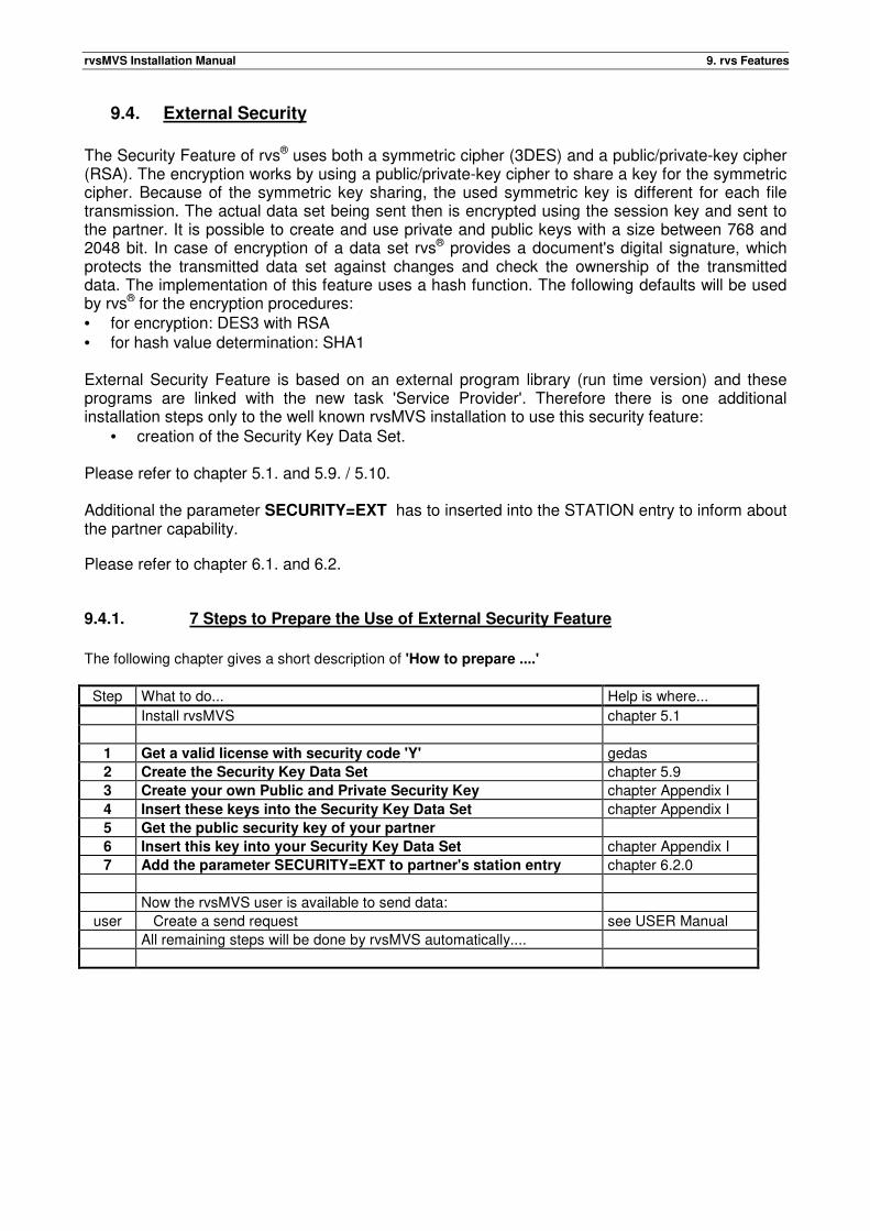
rvsMVS Installation Manual 9. rvs Features
9.4. External Security
The Security Feature of rvs® uses both a symmetric cipher (3DES) and a public/private-key cipher (RSA). The encryption works by using a public/private-key cipher to share a key for the symmetric cipher. Because of the symmetric key sharing, the used symmetric key is different for each file transmission. The actual data set being sent then is encrypted using the session key and sent to the partner. It is possible to create and use private and public keys with a size between 768 and 2048 bit. In case of encryption of a data set rvs® provides a document's digital signature, which protects the transmitted data set against changes and check the ownership of the transmitted data. The implementation of this feature uses a hash function. The following defaults will be used by rvs® for the encryption procedures: • for encryption: DES3 with RSA • for hash value determination: SHA1 External Security Feature is based on an external program library (run time version) and these programs are linked with the new task 'Service Provider'. Therefore there is one additional installation steps only to the well known rvsMVS installation to use this security feature:
• creation of the Security Key Data Set. Please refer to chapter 5.1. and 5.9. / 5.10. Additional the parameter SECURITY=EXT has to inserted into the STATION entry to inform about the partner capability.
Please refer to chapter 6.1. and 6.2.
9.4.1. 7 Steps to Prepare the Use of External Security Feature
The following chapter gives a short description of 'How to prepare ....'
Step What to do... Help is where...
Install rvsMVS chapter 5.1
1 Get a valid license with security code 'Y' gedas
2 Create the Security Key Data Set chapter 5.9
3 Create your own Public and Private Security Key chapter Appendix I
4 Insert these keys into the Security Key Data Set chapter Appendix I
5 Get the public security key of your partner
6 Insert this key into your Security Key Data Set chapter Appendix I
7 Add the parameter SECURITY=EXT to partner's station entry chapter 6.2.0
Now the rvsMVS user is available to send data:
user Create a send request see USER Manual
All remaining steps will be done by rvsMVS automatically....

rvsMVS Installation Manual 9. rvs Features
This page will be intentionally empty.
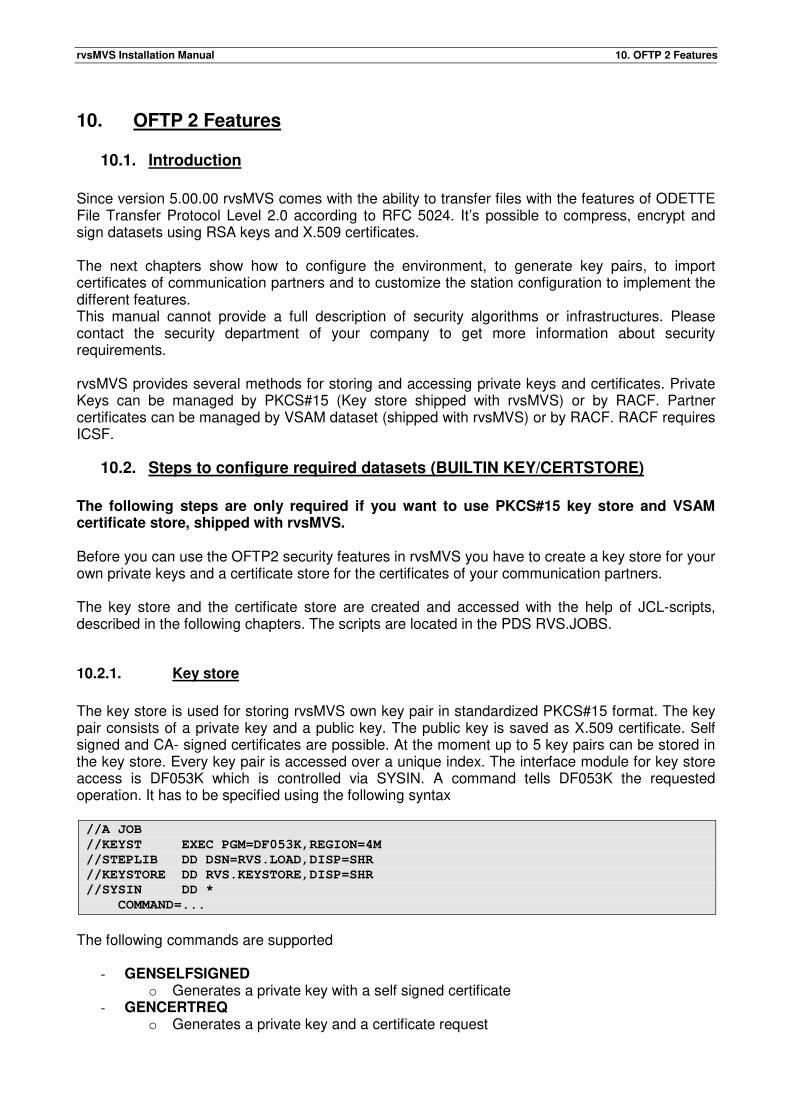
rvsMVS Installation Manual 10. OFTP 2 Features
10. OFTP 2 Features
10.1. Introduction
Since version 5.00.00 rvsMVS comes with the ability to transfer files with the features of ODETTE File Transfer Protocol Level 2.0 according to RFC 5024. It’s possible to compress, encrypt and sign datasets using RSA keys and X.509 certificates. The next chapters show how to configure the environment, to generate key pairs, to import certificates of communication partners and to customize the station configuration to implement the different features. This manual cannot provide a full description of security algorithms or infrastructures. Please contact the security department of your company to get more information about security requirements. rvsMVS provides several methods for storing and accessing private keys and certificates. Private Keys can be managed by PKCS#15 (Key store shipped with rvsMVS) or by RACF. Partner certificates can be managed by VSAM dataset (shipped with rvsMVS) or by RACF. RACF requires ICSF.
10.2. Steps to configure required datasets (BUILTIN KEY/CERTSTORE)
The following steps are only required if you want to use PKCS#15 key store and VSAM certificate store, shipped with rvsMVS. Before you can use the OFTP2 security features in rvsMVS you have to create a key store for your own private keys and a certificate store for the certificates of your communication partners. The key store and the certificate store are created and accessed with the help of JCL-scripts, described in the following chapters. The scripts are located in the PDS RVS.JOBS.
10.2.1. Key store
The key store is used for storing rvsMVS own key pair in standardized PKCS#15 format. The key pair consists of a private key and a public key. The public key is saved as X.509 certificate. Self signed and CA- signed certificates are possible. At the moment up to 5 key pairs can be stored in the key store. Every key pair is accessed over a unique index. The interface module for key store access is DF053K which is controlled via SYSIN. A command tells DF053K the requested operation. It has to be specified using the following syntax //A JOB
//KEYST EXEC PGM=DF053K,REGION=4M
//STEPLIB DD DSN=RVS.LOAD,DISP=SHR
//KEYSTORE DD RVS.KEYSTORE,DISP=SHR
//SYSIN DD *
COMMAND=...
The following commands are supported
- GENSELFSIGNED o Generates a private key with a self signed certificate
- GENCERTREQ o Generates a private key and a certificate request
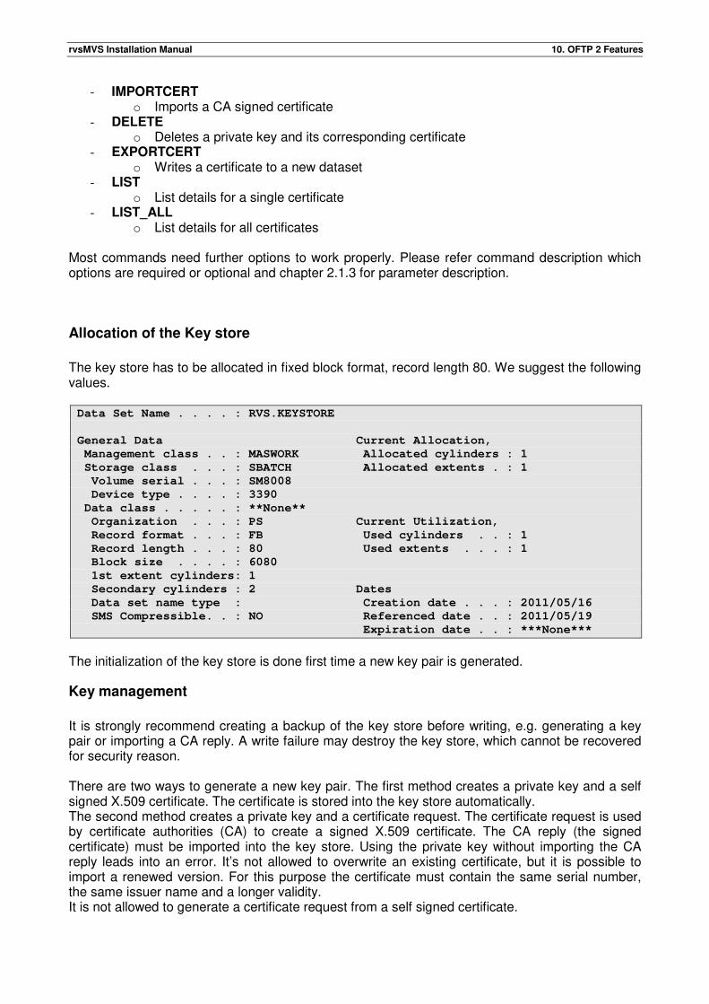
rvsMVS Installation Manual 10. OFTP 2 Features
- IMPORTCERT o Imports a CA signed certificate
- DELETE o Deletes a private key and its corresponding certificate
- EXPORTCERT o Writes a certificate to a new dataset
- LIST o List details for a single certificate
- LIST_ALL o List details for all certificates
Most commands need further options to work properly. Please refer command description which options are required or optional and chapter 2.1.3 for parameter description.
Allocation of the Key store
The key store has to be allocated in fixed block format, record length 80. We suggest the following values. Data Set Name . . . . : RVS.KEYSTORE
General Data Current Allocation,
Management class . . : MASWORK Allocated cylinders : 1
Storage class . . . : SBATCH Allocated extents . : 1
Volume serial . . . : SM8008
Device type . . . . : 3390
Data class . . . . . : **None**
Organization . . . : PS Current Utilization,
Record format . . . : FB Used cylinders . . : 1
Record length . . . : 80 Used extents . . . : 1
Block size . . . . : 6080
1st extent cylinders: 1
Secondary cylinders : 2 Dates
Data set name type : Creation date . . . : 2011/05/16
SMS Compressible. . : NO Referenced date . . : 2011/05/19
Expiration date . . : ***None***
The initialization of the key store is done first time a new key pair is generated.
Key management
It is strongly recommend creating a backup of the key store before writing, e.g. generating a key pair or importing a CA reply. A write failure may destroy the key store, which cannot be recovered for security reason. There are two ways to generate a new key pair. The first method creates a private key and a self signed X.509 certificate. The certificate is stored into the key store automatically. The second method creates a private key and a certificate request. The certificate request is used by certificate authorities (CA) to create a signed X.509 certificate. The CA reply (the signed certificate) must be imported into the key store. Using the private key without importing the CA reply leads into an error. It’s not allowed to overwrite an existing certificate, but it is possible to import a renewed version. For this purpose the certificate must contain the same serial number, the same issuer name and a longer validity. It is not allowed to generate a certificate request from a self signed certificate.
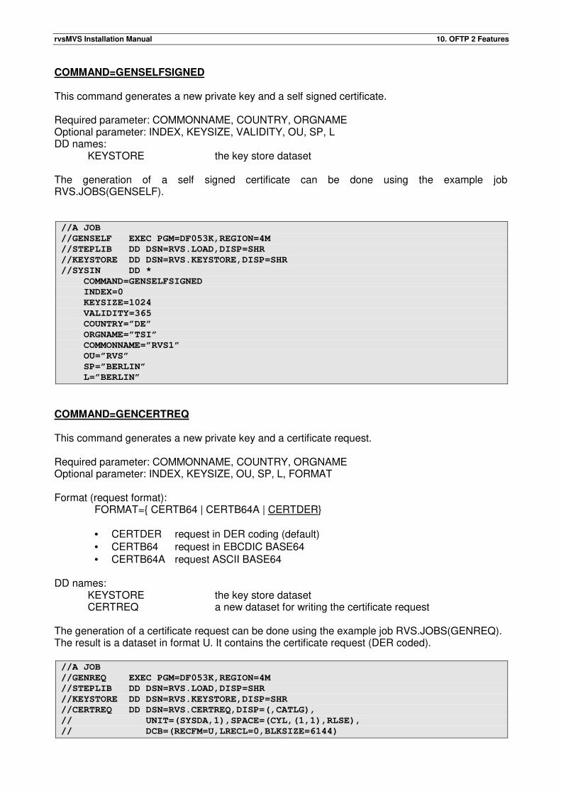
rvsMVS Installation Manual 10. OFTP 2 Features
COMMAND=GENSELFSIGNED This command generates a new private key and a self signed certificate. Required parameter: COMMONNAME, COUNTRY, ORGNAME Optional parameter: INDEX, KEYSIZE, VALIDITY, OU, SP, L DD names:
KEYSTORE the key store dataset The generation of a self signed certificate can be done using the example job RVS.JOBS(GENSELF). //A JOB
//GENSELF EXEC PGM=DF053K,REGION=4M
//STEPLIB DD DSN=RVS.LOAD,DISP=SHR
//KEYSTORE DD DSN=RVS.KEYSTORE,DISP=SHR
//SYSIN DD *
COMMAND=GENSELFSIGNED
INDEX=0
KEYSIZE=1024
VALIDITY=365
COUNTRY=”DE”
ORGNAME=”TSI”
COMMONNAME=”RVS1”
OU=”RVS”
SP=”BERLIN”
L=”BERLIN”
COMMAND=GENCERTREQ This command generates a new private key and a certificate request. Required parameter: COMMONNAME, COUNTRY, ORGNAME Optional parameter: INDEX, KEYSIZE, OU, SP, L, FORMAT Format (request format): FORMAT={ CERTB64 | CERTB64A | CERTDER}
• CERTDER request in DER coding (default) • CERTB64 request in EBCDIC BASE64 • CERTB64A request ASCII BASE64
DD names:
KEYSTORE the key store dataset CERTREQ a new dataset for writing the certificate request
The generation of a certificate request can be done using the example job RVS.JOBS(GENREQ). The result is a dataset in format U. It contains the certificate request (DER coded). //A JOB
//GENREQ EXEC PGM=DF053K,REGION=4M
//STEPLIB DD DSN=RVS.LOAD,DISP=SHR
//KEYSTORE DD DSN=RVS.KEYSTORE,DISP=SHR
//CERTREQ DD DSN=RVS.CERTREQ,DISP=(,CATLG),
// UNIT=(SYSDA,1),SPACE=(CYL,(1,1),RLSE),
// DCB=(RECFM=U,LRECL=0,BLKSIZE=6144)
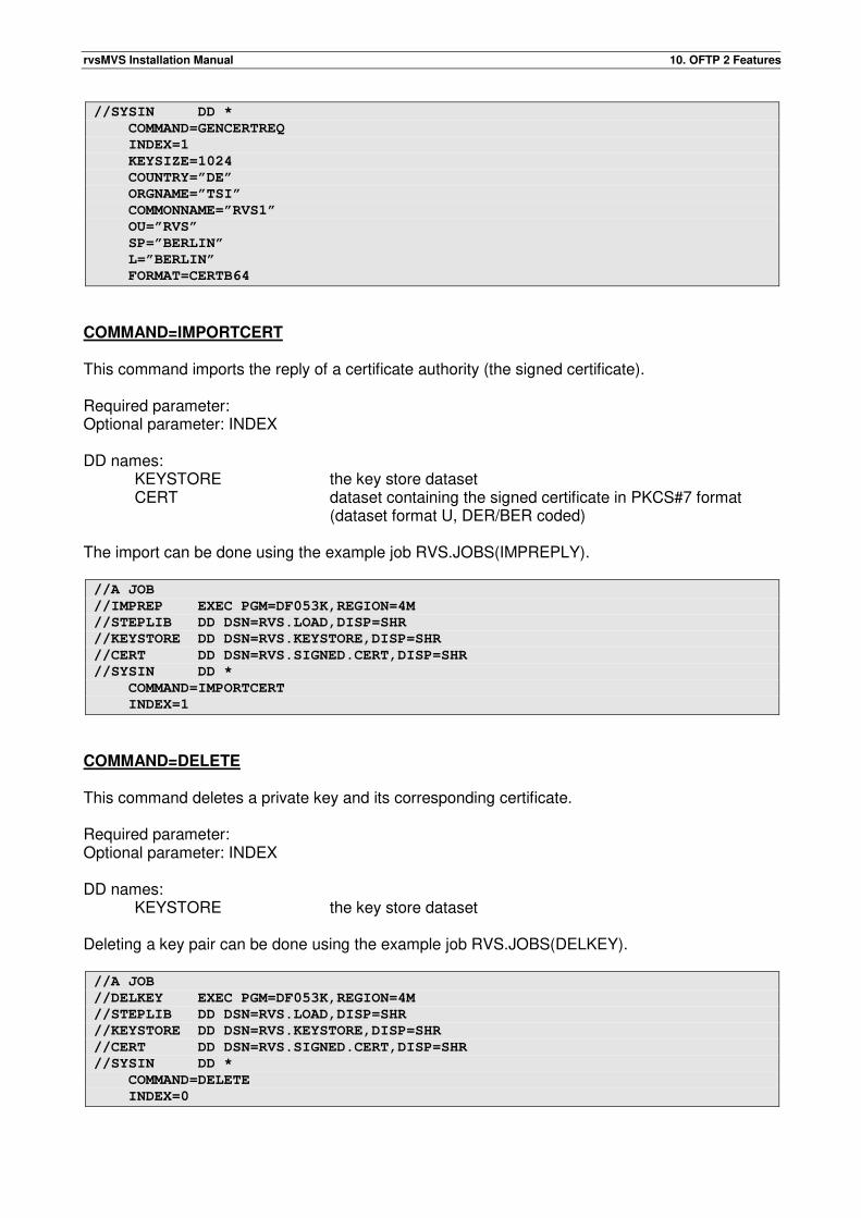
rvsMVS Installation Manual 10. OFTP 2 Features
//SYSIN DD *
COMMAND=GENCERTREQ
INDEX=1
KEYSIZE=1024
COUNTRY=”DE”
ORGNAME=”TSI”
COMMONNAME=”RVS1”
OU=”RVS”
SP=”BERLIN”
L=”BERLIN”
FORMAT=CERTB64
COMMAND=IMPORTCERT This command imports the reply of a certificate authority (the signed certificate). Required parameter: Optional parameter: INDEX DD names:
KEYSTORE the key store dataset CERT dataset containing the signed certificate in PKCS#7 format
(dataset format U, DER/BER coded) The import can be done using the example job RVS.JOBS(IMPREPLY). //A JOB
//IMPREP EXEC PGM=DF053K,REGION=4M
//STEPLIB DD DSN=RVS.LOAD,DISP=SHR
//KEYSTORE DD DSN=RVS.KEYSTORE,DISP=SHR
//CERT DD DSN=RVS.SIGNED.CERT,DISP=SHR
//SYSIN DD *
COMMAND=IMPORTCERT
INDEX=1
COMMAND=DELETE This command deletes a private key and its corresponding certificate. Required parameter: Optional parameter: INDEX DD names:
KEYSTORE the key store dataset Deleting a key pair can be done using the example job RVS.JOBS(DELKEY). //A JOB
//DELKEY EXEC PGM=DF053K,REGION=4M
//STEPLIB DD DSN=RVS.LOAD,DISP=SHR
//KEYSTORE DD DSN=RVS.KEYSTORE,DISP=SHR
//CERT DD DSN=RVS.SIGNED.CERT,DISP=SHR
//SYSIN DD *
COMMAND=DELETE
INDEX=0
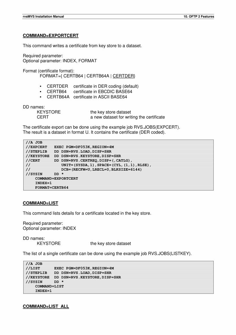
rvsMVS Installation Manual 10. OFTP 2 Features
COMMAND=EXPORTCERT This command writes a certificate from key store to a dataset. Required parameter: Optional parameter: INDEX, FORMAT Format (certificate format): FORMAT={ CERTB64 | CERTB64A | CERTDER}
• CERTDER certificate in DER coding (default) • CERTB64 certificate in EBCDIC BASE64 • CERTB64A certificate in ASCII BASE64
DD names:
KEYSTORE the key store dataset CERT a new dataset for writing the certificate
The certificate export can be done using the example job RVS.JOBS(EXPCERT). The result is a dataset in format U. It contains the certificate (DER coded). //A JOB
//EXPCERT EXEC PGM=DF053K,REGION=4M
//STEPLIB DD DSN=RVS.LOAD,DISP=SHR
//KEYSTORE DD DSN=RVS.KEYSTORE,DISP=SHR
//CERT DD DSN=RVS.CERTREQ,DISP=(,CATLG),
// UNIT=(SYSDA,1),SPACE=(CYL,(1,1),RLSE),
// DCB=(RECFM=U,LRECL=0,BLKSIZE=6144)
//SYSIN DD *
COMMAND=EXPORTCERT
INDEX=1
FORMAT=CERTB64
COMMAND=LIST This command lists details for a certificate located in the key store. Required parameter: Optional parameter: INDEX DD names:
KEYSTORE the key store dataset
The list of a single certificate can be done using the example job RVS.JOBS(LISTKEY). //A JOB
//LIST EXEC PGM=DF053K,REGION=4M
//STEPLIB DD DSN=RVS.LOAD,DISP=SHR
//KEYSTORE DD DSN=RVS.KEYSTORE,DISP=SHR
//SYSIN DD *
COMMAND=LIST
INDEX=1
COMMAND=LIST_ALL
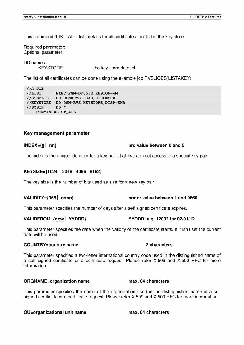
rvsMVS Installation Manual 10. OFTP 2 Features
This command “LIST_ALL” lists details for all certificates located in the key store. Required parameter: Optional parameter: DD names:
KEYSTORE the key store dataset
The list of all certificates can be done using the example job RVS.JOBS(LISTAKEY). //A JOB
//LIST EXEC PGM=DF053K,REGION=4M
//STEPLIB DD DSN=RVS.LOAD,DISP=SHR
//KEYSTORE DD DSN=RVS.KEYSTORE,DISP=SHR
//SYSIN DD *
COMMAND=LIST_ALL
Key management parameter
INDEX={0 nn} nn: value between 0 and 5 The index is the unique identifier for a key pair. It allows a direct access to a special key pair. KEYSIZE={1024 2048 | 4096 | 8192} The key size is the number of bits used as size for a new key pair. VALIDITY={365 nnnn} nnnn: value between 1 and 9660 This parameter specifies the number of days after a self signed certificate expires. VALIDFROM={now YYDDD} YYDDD: e.g. 12032 for 02/01/12 This parameter specifies the date when the validity of the certificate starts. If it isn’t set the current date will be used. COUNTRY=country name 2 characters This parameter specifies a two-letter international country code used in the distinguished name of a self signed certificate or a certificate request. Please refer X.509 and X.500 RFC for more information. ORGNAME=organization name max. 64 characters This parameter specifies the name of the organization used in the distinguished name of a self signed certificate or a certificate request. Please refer X.509 and X.500 RFC for more information. OU=organizational unit name max. 64 characters
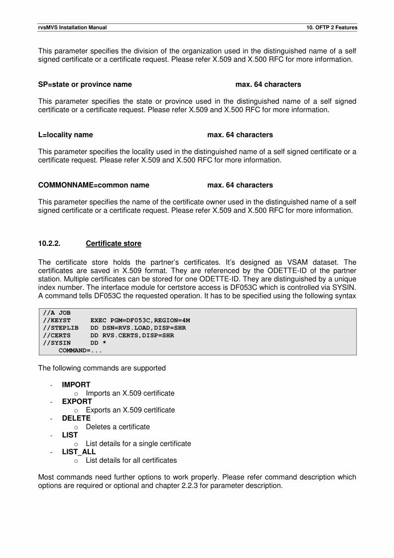
rvsMVS Installation Manual 10. OFTP 2 Features
This parameter specifies the division of the organization used in the distinguished name of a self signed certificate or a certificate request. Please refer X.509 and X.500 RFC for more information. SP=state or province name max. 64 characters This parameter specifies the state or province used in the distinguished name of a self signed certificate or a certificate request. Please refer X.509 and X.500 RFC for more information. L=locality name max. 64 characters This parameter specifies the locality used in the distinguished name of a self signed certificate or a certificate request. Please refer X.509 and X.500 RFC for more information. COMMONNAME=common name max. 64 characters This parameter specifies the name of the certificate owner used in the distinguished name of a self signed certificate or a certificate request. Please refer X.509 and X.500 RFC for more information.
10.2.2. Certificate store
The certificate store holds the partner’s certificates. It’s designed as VSAM dataset. The certificates are saved in X.509 format. They are referenced by the ODETTE-ID of the partner station. Multiple certificates can be stored for one ODETTE-ID. They are distinguished by a unique index number. The interface module for certstore access is DF053C which is controlled via SYSIN. A command tells DF053C the requested operation. It has to be specified using the following syntax //A JOB
//KEYST EXEC PGM=DF053C,REGION=4M
//STEPLIB DD DSN=RVS.LOAD,DISP=SHR
//CERTS DD RVS.CERTS,DISP=SHR
//SYSIN DD *
COMMAND=...
The following commands are supported
- IMPORT o Imports an X.509 certificate
- EXPORT o Exports an X.509 certificate
- DELETE o Deletes a certificate
- LIST o List details for a single certificate
- LIST_ALL o List details for all certificates
Most commands need further options to work properly. Please refer command description which options are required or optional and chapter 2.2.3 for parameter description.
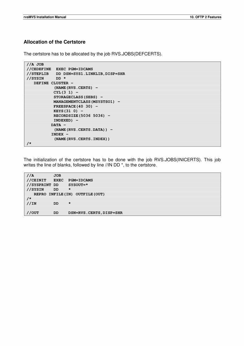
rvsMVS Installation Manual 10. OFTP 2 Features
Allocation of the Certstore
The certstore has to be allocated by the job RVS.JOBS(DEFCERTS). //A JOB
//CEDEFINE EXEC PGM=IDCAMS
//STEPLIB DD DSN=SYS1.LINKLIB,DISP=SHR
//SYSIN DD *
DEFINE CLUSTER -
(NAME(RVS.CERTS) -
CYL(3 1) -
STORAGECLASS(SEBS) -
MANAGEMENTCLASS(MSYSTSO1) -
FREESPACE(40 30) -
KEYS(31 0) -
RECORDSIZE(5036 5036) -
INDEXED) -
DATA -
(NAME(RVS.CERTS.DATA)) -
INDEX -
(NAME(RVS.CERTS.INDEX))
/*
The initialization of the certstore has to be done with the job RVS.JOBS(INICERTS). This job writes the line of blanks, followed by line //IN DD *, to the certstore. //A JOB
//CEINIT EXEC PGM=IDCAMS
//SYSPRINT DD SYSOUT=*
//SYSIN DD *
REPRO INFILE(IN) OUTFILE(OUT)
/*
//IN DD *
//OUT DD DSN=RVS.CERTS,DISP=SHR
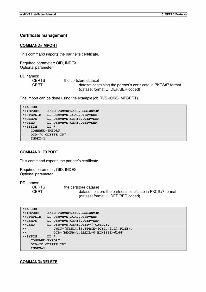
rvsMVS Installation Manual 10. OFTP 2 Features
Certificate management
COMMAND=IMPORT This command imports the partner’s certificate. Required parameter: OID, INDEX Optional parameter: DD names:
CERTS the certstore dataset CERT dataset containing the partner’s certificate in PKCS#7 format (dataset format U, DER/BER coded)
The import can be done using the example job RVS.JOBS(IMPCERT). //A JOB
//IMPORT EXEC PGM=DF053C,REGION=4M
//STEPLIB DD DSN=RVS.LOAD,DISP=SHR
//CERTS DD DSN=RVS.CERTS,DISP=SHR
//CERT DD DSN=RVS.CERT,DISP=SHR
//SYSIN DD *
COMMAND=IMPORT
OID=”O ODETTE ID”
INDEX=1
COMMAND=EXPORT This command exports the partner’s certificate. Required parameter: OID, INDEX Optional parameter: DD names:
CERTS the certstore dataset CERT dataset to store the partner’s certificate in PKCS#7 format (dataset format U, DER/BER coded)
//A JOB
//IMPORT EXEC PGM=DF053C,REGION=4M
//STEPLIB DD DSN=RVS.LOAD,DISP=SHR
//CERTS DD DSN=RVS.CERTS,DISP=SHR
//CERT DD DSN=RVS.CERT,DISP=(,CATLG),
// UNIT=(SYSDA,1),SPACE=(CYL,(1,1),RLSE),
// DCB=(RECFM=U,LRECL=0,BLKSIZE=6144)
//SYSIN DD *
COMMAND=EXPORT
OID=”O ODETTE ID”
INDEX=1
COMMAND=DELETE
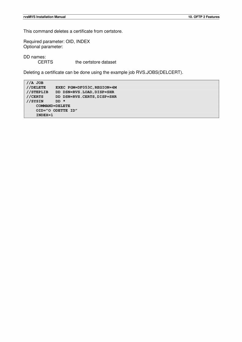
rvsMVS Installation Manual 10. OFTP 2 Features
This command deletes a certificate from certstore. Required parameter: OID, INDEX Optional parameter: DD names:
CERTS the certstore dataset Deleting a certificate can be done using the example job RVS.JOBS(DELCERT). //A JOB
//DELETE EXEC PGM=DF053C,REGION=4M
//STEPLIB DD DSN=RVS.LOAD,DISP=SHR
//CERTS DD DSN=RVS.CERTS,DISP=SHR
//SYSIN DD *
COMMAND=DELETE
OID=”O ODETTE ID”
INDEX=1
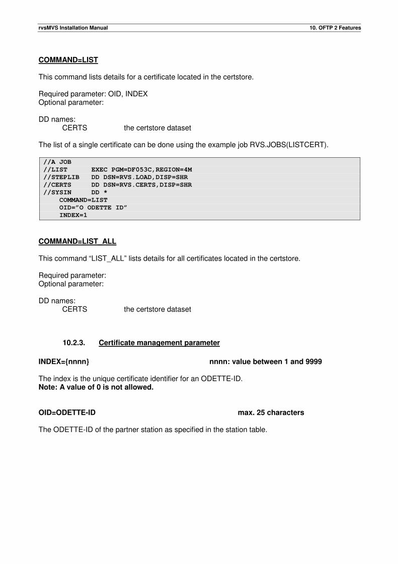
rvsMVS Installation Manual 10. OFTP 2 Features
COMMAND=LIST This command lists details for a certificate located in the certstore. Required parameter: OID, INDEX Optional parameter: DD names:
CERTS the certstore dataset
The list of a single certificate can be done using the example job RVS.JOBS(LISTCERT). //A JOB
//LIST EXEC PGM=DF053C,REGION=4M
//STEPLIB DD DSN=RVS.LOAD,DISP=SHR
//CERTS DD DSN=RVS.CERTS,DISP=SHR
//SYSIN DD *
COMMAND=LIST
OID=”O ODETTE ID”
INDEX=1
COMMAND=LIST_ALL This command “LIST_ALL” lists details for all certificates located in the certstore. Required parameter: Optional parameter: DD names:
CERTS the certstore dataset
10.2.3. Certificate management parameter
INDEX={nnnn} nnnn: value between 1 and 9999 The index is the unique certificate identifier for an ODETTE-ID. Note: A value of 0 is not allowed. OID=ODETTE-ID max. 25 characters The ODETTE-ID of the partner station as specified in the station table.
rvsMVS Installation Manual 10. OFTP 2 Features
10.3. Steps to configure RACF access (RACF KEY/CERTSTORE)
The following steps are only required if you want to use RACF as key store and certificate store.
• rvsMVS must have OMVS segment defined in RACF
• rvsMVS requires read access on several resources
o CSFPKD in CLASS CSFSERV
o CSFDSG in CLASS CSFSERV
o IRR.DIGTCERT GENCERT in CLASS FACILITY (CONTROL ACCESS)
o IRR.DIGTCERT.ADD in CLASS FACILITY
o IRR.DIGTCERT.LIST in CLASS FACILITY
o IRR.DIGTCERT.LISTRING in CLASS FACILITY
• Private Keys either have to be protected by hardware (keyword PCICC) or created as clear
key (without this keyword).
The private key must be generated with the attribute SITE or must be owned by rvsMVS
user.
• The own key pair (private key and certificate) and the partner certificates have to be
connected to the same RACF key ring. The key ring must by accessible by rvsMVS.
• The complete certificate chain (all issuing CA and ROOT certificates) have to be connected
to the key ring.
10.3.1. Examples
The configuration of the RACF resources must be done by the RACF administrator who is aware of the effects on the whole system and might adopt configuration details to specific site requirements (i.e. some resource profiles or generic profiles may already be in use, user may already have OMVS segment). The decision, which of the steps (if any) of the RACF configuration might be delegated to the rvs administrator depends on the rules which are in place on site. If desired, the rvs admin must be given sufficient authorization. Assumed names in this example (may be configured to be different):
TESTUSR user who runs rvsMVS
TESTKEYLABEL label of the own key pair (private key and signed certificate)
PARTNERKEYLABEL label of the public key of partner station (signed certificate)
TESTCA label of self signed root cert to sign TESTKEYLABEL
TESTRING label of keying to hold all keys and certificates of relevance to rvsMVS
Define OMVS segment for user who runs rvsMVS (RACF-admin):
rvsMVS Installation Manual 10. OFTP 2 Features
ALTUSER TESTUSR OMVS(HOME(‘/u/testusr’) PROGRAM(‘/bin/sh’))
Activate the needed resource classes in RACF and let them reside in-storage (RACF-admin):
SETROPTS RACLIST(CSFSERV) CLASSACT(CSFSERV)
SETROPTS RACLIST(FACILITY) CLASSACT(FACILITY)
Define the needed resource profiles in RACF (RACF-admin):
RDEFINE CSFSERV CSFPKD UACC(NONE)
RDEFINE CSFSERV CSFDSG UACC(NONE)
RDEFINE FACILITY IRR.DIGTCERT.*
RDEFINE FACILITY IRR.DIGTCERT.ADD
RDEFINE FACILITY IRR.DIGTCERT.CONNECT
RDEFINE FACILITY IRR.DIGTCERT.GENCERT
Give permission to use needed resource profiles to user who runs rvsMVS (RACF-admin):
PERMIT CSFPKD CLASS(CSFSERV) ID(TESTUSR) ACC(READ)
PERMIT CSFPKI CLASS(CSFSERV) ID(TESTUSR) ACC(READ)
PERMIT CSFDSG CLASS(CSFSERV) ID(TESTUSR) ACC(READ)
PERMIT IRR.DIGTCERT.* CLASS(FACILITY) ID(TESTUSR) ACC(READ)
PERMIT IRR.DIGTCERT.CONNECT CLASS(FACILITY) ID(TESTUSR) ACC(UPDATE)
PERMIT IRR.DIGTCERT.GENCERT CLASS(FACILITY) ID(TESTUSR) ACC(CONTROL)
Refresh the in-storage RACF profiles (RACF-admin):
SETROPTS RACLIST(CSFSERV) REFRESH
SETROPTS RACLIST(FACILITY) REFRESH
Create a keying for your rvsMVS (RACF-admin):
RACDCERT ADDRING(TESTRING) ID(TESTUSR)
Create a self signed key for CERTAUTH with the purpose to sign your test key (RACF-admin):
RACDCERT GENCERT CERTAUTH WITHLABEL(‘TESTCA’) –
SUBJECTSDN(CN(‘TESTCA’)) SIZE(1024) –
NOTAFTER(DATE(2015/01/15)) KEYUSAGE(CERTSIGN)
Generate a signed key pair for your test user (=rvsMVS certificate) (RACF-admin, maybe rvs-admin):
RACDCERT GENCERT ID(TESTUSR) WITHLABEL(‘TESTKEYLABEL’) –
SUBJECTSDN(CN(‘TEST’)) SIZE(1024) NOTAFTER(DATE(2015/01/15)) –
KEYUSAGE (HANDSHAKE DATAENCRYPT) –
SIGNWITH(CERTAUTH LABEL(‘TESTCA’)) PCICC
The keyword PCICC defines the private key as hardware protected. Without this keyword the private key is
created as clear key.
If you are using an IKJEFT01 utility and running a batch job in a parallel sysplex environment, make sure
your job is running in the same LPAR that RVS will run. You can use the /*JOBPARM S=XXXX statement to
do that.
Connect your generated key to the keying (RACF-admin, maybe rvs-admin):
RACDCERT CONNECT (ID(TESTUSR) LABEL(‘TESTKEYLABEL’) –
RING(TESTRING) USAGE(PERSONAL)) ID(TESTUSR)
rvsMVS Installation Manual 10. OFTP 2 Features
Connect the signing key(s) (all keys in the trust chain, in case of self-signature just the TESTCA) to the key
ring (RACF-admin):
RACDCERT CONNECT (CERTAUTH LABEL(‘TESTCA’) -
RING(TESTRING) USAGE(CERTAUTH)) ID(TESTUSR)
Export your certificate to be used by partner stations:
RACDCERT EXPORT (LABEL(‘TESTKEYLABEL’)) ID(TESTUSR) –
DSN(‘FIX0BKR.CERT.OWNCERT.CER’) FORMAT(CERTDER)
If CERSTORE=RACF:
Import the certificate of partner station (RACF-admin, maybe rvs-admin):
RACDCERT ADD('R02.TLS.EVO.TEP') ID(TESTUSR) – TRUST WITHLABEL('PARTNERKEYLABEL')
Dataset must have VB-format.
Connect the partner certificate to the keying (RACF-admin, maybe rvs-admin):
RACDCERT CONNECT(ID(TESTUSR) LABEL('PARTNERKEYLABEL') – RING(TESTRING) USAGE(PERSONAL)) ID(TESTUSR)
In this example, the partner certificate is a self signed one.
In case of a CA-signed partner certificate, all keys in the trust chain must be connected to the keying, too.
The certificate named in the CERLABEL parameter of STATIONS member however must always be the
public key certificate of the partner station.
Refresh the in-storage RACF profiles (RACF-admin, maybe rvs-admin):
SETROPTS RACLIST(FACILITY) REFRESH
Useful commands to list information:
LISTUSER (TESTUSR) OMVS
SEARCH CLASS(CSFSERV)
RLIST CSFSERV * AUTHUSER
RACDCERT LISTRING(*) ID(TESTUSR)
RACDCERT LIST ID(TESTUSR)
RACDCERT LIST (LABEL(‘TESTCA’)) CERTAUTH
In case of key protection by RACF:
Check, if keys are protected:
SEARCH CLASS(CSFKEYS)
IRR.DIGTCERT.** (G)
Define resource profile for user:
RDEFINE CSFKEYS IRR.DIGTCERT.TESTUSR.* UACC(NONE)
SETROPTS RACLIST(CSFKEYS) REFRESH
Give permission to use own keys:
PERMIT IRR.DIGTCERT.TESTUSR.* CLASS(CSFKEYS) ID(TESTUSR) ACC(READ)
SETROPTS RACLIST(CSFKEYS) REFRESH
rvsMVS Installation Manual 10. OFTP 2 Features
Configure parameters in TABLES Dataset of rvsMVS (rvs-admin):
STATIONS:
SID=TE2, ADDR='RVS TEST',
ODETID='ORVSTEST',
SENDPW=XXX,
RECVPW=XXX,
AUTODIAL=YES,
LSIZE=30000,
CREDIT=999,
ISTATUS=ACTIVE,
ACME=T,
TCPIPADR=10.33.71.94,
TCPPORT=3306,
TCPSESS=99,
EERPAD=YES,
OFTPV=2.0,
SECFSET=OFTP2,
SECURITY=YES
COMPRESS=NO,
CERSTORE=RACF
CERLABEL.1=PARTNERCERT1
CERLABEL.2=PARTNERCERT2
CERINDEX=2
KEYINDEX=1
TCPSESS=1
CNTL: KEYRING=TESTRING
KEYLABEL.1=KEYLABEL1
KEYLABEL.2=KEYLABEL2
KEYINDEX=2
KEYSTORE=RACF
CERSTORE=RACF
Remarks: KEYSTORE=RACF: RvsMVS supports multiple KEYLABELs and CERTLABELs via index. KEYLABELs and KEYINDEX can be defined in CNTL member and CERLABELS and CERINDEX can be defined in STATIONS member for each partner station. If the CERINDEX is greater than 0, the certificate with this index is used for encryption to this partner station. If CERINDEX is 0 or not given, the certificate which is valid and has the longest validity is used for encryption to this partner station. RvsMVS finds certificates for signed files (check signing) automatically. If the KEYINDEX is greater than 0, the key with this index is used to sign files. If KEYINDEX is 0 or not given, the key which is valid and has the shortest validity is used to sign files. RvsMVS finds keys for decryption automatically.
KEYSTORE=BUILTIN RvsMVS pay attention to all keys which are stored in p15-keystore and to all certificates which are imported for the partner station (VSAM dataset).
rvsMVS Installation Manual 10. OFTP 2 Features
If the CERINDEX is greater than 0, the certificate with this index is used for encryption to this partner station. If CERINDEX is 0 or not given, the certificate which is valid and has the longest validity is used for encryption to this partner station. RvsMVS finds certificates for signed files (check signing) automatically. If the KEYINDEX is greater than 0, the key with this index is used to sign files. If KEYINDEX is 0 or not given, the key which is valid and has the shortest validity is used to sign files. RvsMVS finds keys for decryption automatically. CEEOPTS:
MSGFILE(RVSCMSG,FBA,121,0,ENQ),RPTOPTS(OFF),RPTSTG(OFF),
TERMTHDACT(UAIMM),
TRAP(ON,NOSPIE)
The Values RPTOPTS and RPTSTG are reporting options. If there is a problem, you will switch it to ON.
Important is that the option POSIX(OFF) is removed!
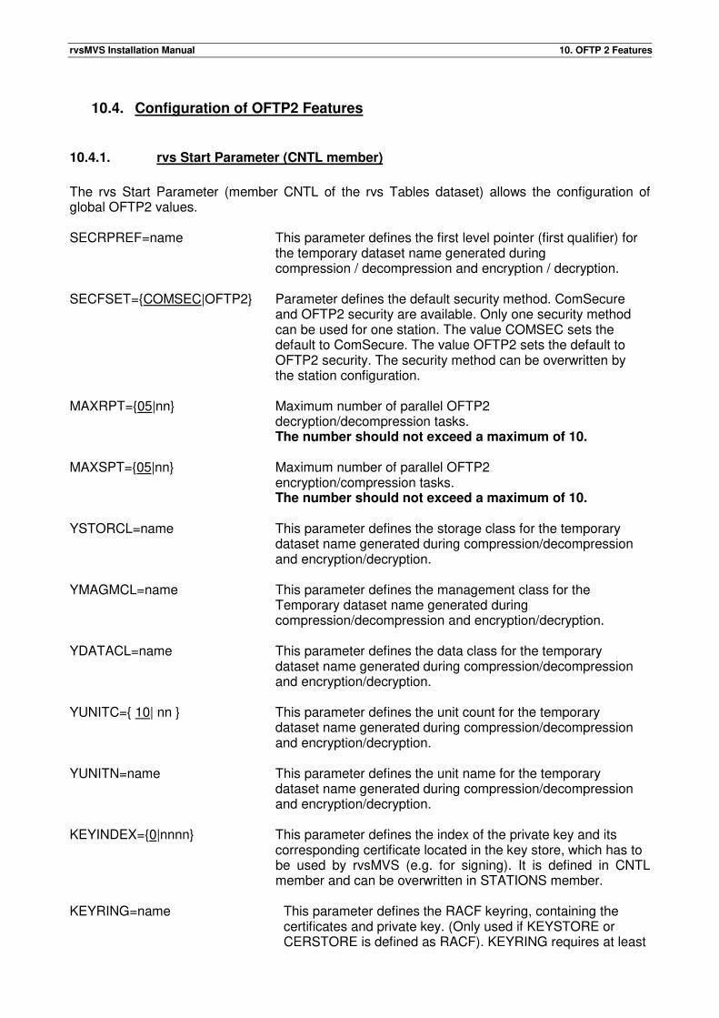
rvsMVS Installation Manual 10. OFTP 2 Features
10.4. Configuration of OFTP2 Features
10.4.1. rvs Start Parameter (CNTL member)
The rvs Start Parameter (member CNTL of the rvs Tables dataset) allows the configuration of global OFTP2 values. SECRPREF=name This parameter defines the first level pointer (first qualifier) for the temporary dataset name generated during compression / decompression and encryption / decryption. SECFSET={COMSEC|OFTP2} Parameter defines the default security method. ComSecure and OFTP2 security are available. Only one security method can be used for one station. The value COMSEC sets the default to ComSecure. The value OFTP2 sets the default to OFTP2 security. The security method can be overwritten by the station configuration. MAXRPT={05|nn} Maximum number of parallel OFTP2 decryption/decompression tasks. The number should not exceed a maximum of 10. MAXSPT={05|nn} Maximum number of parallel OFTP2 encryption/compression tasks. The number should not exceed a maximum of 10. YSTORCL=name This parameter defines the storage class for the temporary dataset name generated during compression/decompression and encryption/decryption. YMAGMCL=name This parameter defines the management class for the Temporary dataset name generated during compression/decompression and encryption/decryption. YDATACL=name This parameter defines the data class for the temporary dataset name generated during compression/decompression and encryption/decryption. YUNITC={ 10| nn } This parameter defines the unit count for the temporary dataset name generated during compression/decompression and encryption/decryption. YUNITN=name This parameter defines the unit name for the temporary dataset name generated during compression/decompression and encryption/decryption. KEYINDEX={0|nnnn} This parameter defines the index of the private key and its corresponding certificate located in the key store, which has to
be used by rvsMVS (e.g. for signing). It is defined in CNTL member and can be overwritten in STATIONS member.
KEYRING=name This parameter defines the RACF keyring, containing the
certificates and private key. (Only used if KEYSTORE or CERSTORE is defined as RACF). KEYRING requires at least
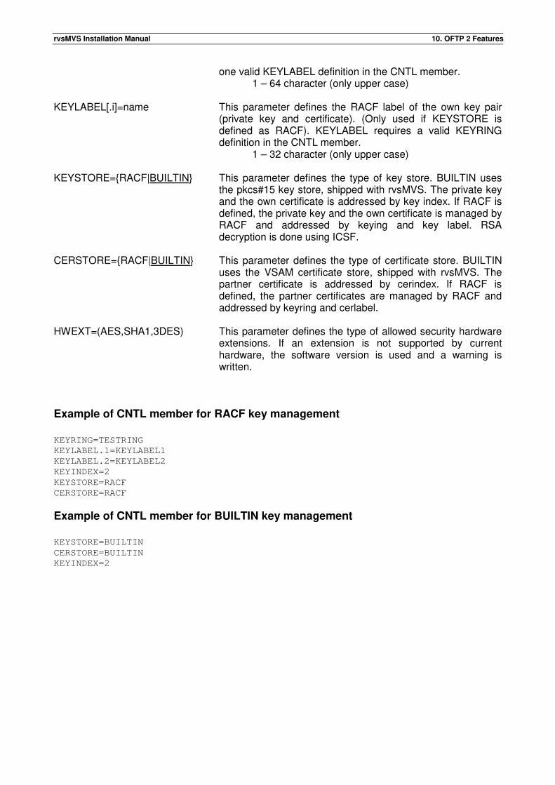
rvsMVS Installation Manual 10. OFTP 2 Features
one valid KEYLABEL definition in the CNTL member. 1 – 64 character (only upper case)
KEYLABEL[.i]=name This parameter defines the RACF label of the own key pair
(private key and certificate). (Only used if KEYSTORE is defined as RACF). KEYLABEL requires a valid KEYRING definition in the CNTL member.
1 – 32 character (only upper case) KEYSTORE={RACF|BUILTIN} This parameter defines the type of key store. BUILTIN uses
the pkcs#15 key store, shipped with rvsMVS. The private key and the own certificate is addressed by key index. If RACF is defined, the private key and the own certificate is managed by RACF and addressed by keying and key label. RSA decryption is done using ICSF.
CERSTORE={RACF|BUILTIN} This parameter defines the type of certificate store. BUILTIN
uses the VSAM certificate store, shipped with rvsMVS. The partner certificate is addressed by cerindex. If RACF is defined, the partner certificates are managed by RACF and addressed by keyring and cerlabel.
HWEXT=(AES,SHA1,3DES) This parameter defines the type of allowed security hardware
extensions. If an extension is not supported by current hardware, the software version is used and a warning is written.
Example of CNTL member for RACF key management
KEYRING=TESTRING
KEYLABEL.1=KEYLABEL1
KEYLABEL.2=KEYLABEL2
KEYINDEX=2
KEYSTORE=RACF
CERSTORE=RACF
Example of CNTL member for BUILTIN key management
KEYSTORE=BUILTIN
CERSTORE=BUILTIN
KEYINDEX=2
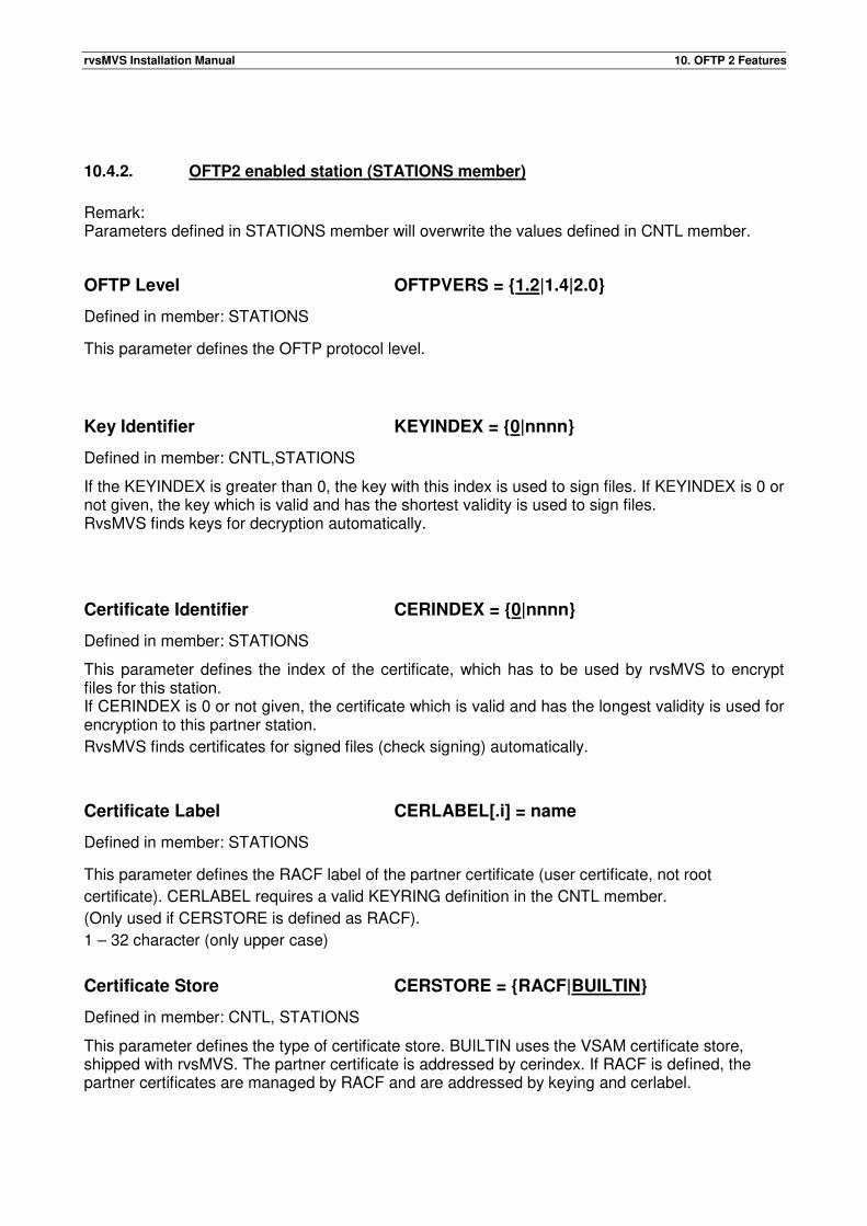
rvsMVS Installation Manual 10. OFTP 2 Features
10.4.2. OFTP2 enabled station (STATIONS member)
Remark: Parameters defined in STATIONS member will overwrite the values defined in CNTL member.
OFTP Level OFTPVERS = {1.2|1.4|2.0}
Defined in member: STATIONS
This parameter defines the OFTP protocol level.
Key Identifier KEYINDEX = {0|nnnn}
Defined in member: CNTL,STATIONS
If the KEYINDEX is greater than 0, the key with this index is used to sign files. If KEYINDEX is 0 or not given, the key which is valid and has the shortest validity is used to sign files. RvsMVS finds keys for decryption automatically.
Certificate Identifier CERINDEX = {0|nnnn}
Defined in member: STATIONS
This parameter defines the index of the certificate, which has to be used by rvsMVS to encrypt files for this station. If CERINDEX is 0 or not given, the certificate which is valid and has the longest validity is used for encryption to this partner station.
RvsMVS finds certificates for signed files (check signing) automatically.
Certificate Label CERLABEL[.i] = name
Defined in member: STATIONS
This parameter defines the RACF label of the partner certificate (user certificate, not root
certificate). CERLABEL requires a valid KEYRING definition in the CNTL member.
(Only used if CERSTORE is defined as RACF).
1 – 32 character (only upper case)
Certificate Store CERSTORE = {RACF|BUILTIN}
Defined in member: CNTL, STATIONS
This parameter defines the type of certificate store. BUILTIN uses the VSAM certificate store, shipped with rvsMVS. The partner certificate is addressed by cerindex. If RACF is defined, the partner certificates are managed by RACF and are addressed by keying and cerlabel.
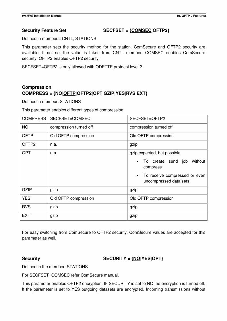
rvsMVS Installation Manual 10. OFTP 2 Features
Security Feature Set SECFSET = {COMSEC|OFTP2}
Defined in members: CNTL, STATIONS
This parameter sets the security method for the station. ComSecure and OFTP2 security are
available. If not set the value is taken from CNTL member. COMSEC enables ComSecure
security. OFTP2 enables OFTP2 security.
SECFSET=OFTP2 is only allowed with ODETTE protocol level 2.
Compression
COMPRESS = {NO|OFTP|OFTP2|OPT|GZIP|YES|RVS|EXT}
Defined in member: STATIONS
This parameter enables different types of compression.
COMPRESS SECFSET=COMSEC SECFSET=OFTP2
NO compression turned off compression turned off
OFTP Old OFTP compression Old OFTP compression
OFTP2 n.a. gzip
OPT n.a. gzip expected, but possible
• To create send job without
compress
• To receive compressed or even
uncompressed data sets
GZIP gzip gzip
YES Old OFTP compression Old OFTP compression
RVS gzip gzip
EXT gzip gzip
For easy switching from ComSecure to OFTP2 security, ComSecure values are accepted for this
parameter as well.
Security SECURITY = {NO|YES|OPT}
Defined in the member: STATIONS
For SECFSET=COMSEC refer ComSecure manual.
This parameter enables OFTP2 encryption. IF SECURITY is set to NO the encryption is turned off.
If the parameter is set to YES outgoing datasets are encrypted. Incoming transmissions without
rvsMVS Installation Manual 10. OFTP 2 Features
encryption are rejected. If the parameter is set to OPT encryption can be enabled when the send
request is created. Encrypted and not encrypted datasets are allowed for incoming transmissions.
For easy switching from ComSecure to OFTP2 security, ComSecure values are accepted for this
parameter as well.
Security Algorithm SECALG = {3DES| AES}
Defined in member: STATIONS
This parameter defines the security algorithm used for file encryption.
This parameter is only allowed if SECFSET=OFTP2 is set.
File Signature FILESIG = {NO|YES|OPT}
Defined in member: STATIONS
This parameter enables the OFTP2 file signature. If FILESIG is set to NO, the file signature is
turned off in both directions. Incoming transmissions containing a signature are rejected. If the
parameter is set to YES, outgoing datasets are signed. Incoming transmissions without signature
are rejected. If the parameter is to OPT, signed and unsigned datasets are accepted on incoming
transmissions. Outgoing datasets are not signed. It can be overwritten during creation of send
entry.
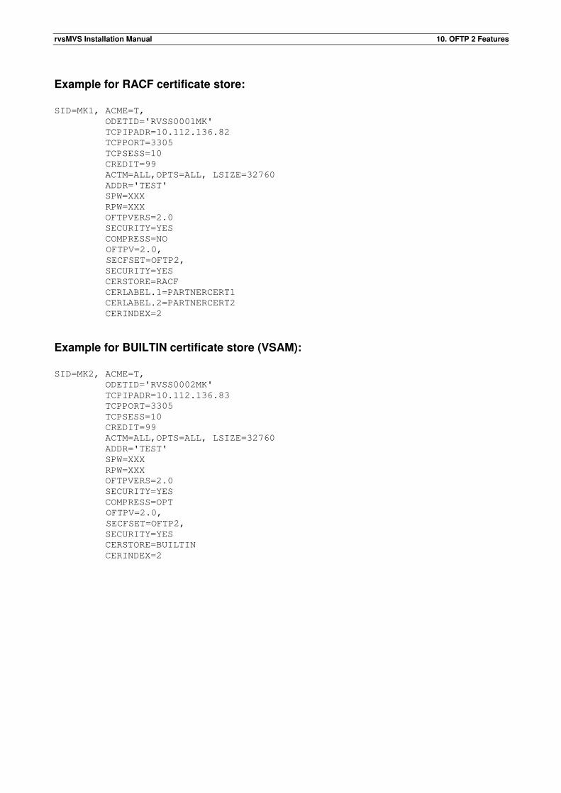
rvsMVS Installation Manual 10. OFTP 2 Features
Example for RACF certificate store:
SID=MK1, ACME=T,
ODETID='RVSS0001MK'
TCPIPADR=10.112.136.82
TCPPORT=3305
TCPSESS=10
CREDIT=99
ACTM=ALL,OPTS=ALL, LSIZE=32760
ADDR='TEST'
SPW=XXX
RPW=XXX
OFTPVERS=2.0
SECURITY=YES
COMPRESS=NO
OFTPV=2.0,
SECFSET=OFTP2,
SECURITY=YES
CERSTORE=RACF
CERLABEL.1=PARTNERCERT1
CERLABEL.2=PARTNERCERT2
CERINDEX=2
Example for BUILTIN certificate store (VSAM):
SID=MK2, ACME=T,
ODETID='RVSS0002MK'
TCPIPADR=10.112.136.83
TCPPORT=3305
TCPSESS=10
CREDIT=99
ACTM=ALL,OPTS=ALL, LSIZE=32760
ADDR='TEST'
SPW=XXX
RPW=XXX
OFTPVERS=2.0
SECURITY=YES
COMPRESS=OPT
OFTPV=2.0,
SECFSET=OFTP2,
SECURITY=YES
CERSTORE=BUILTIN
CERINDEX=2
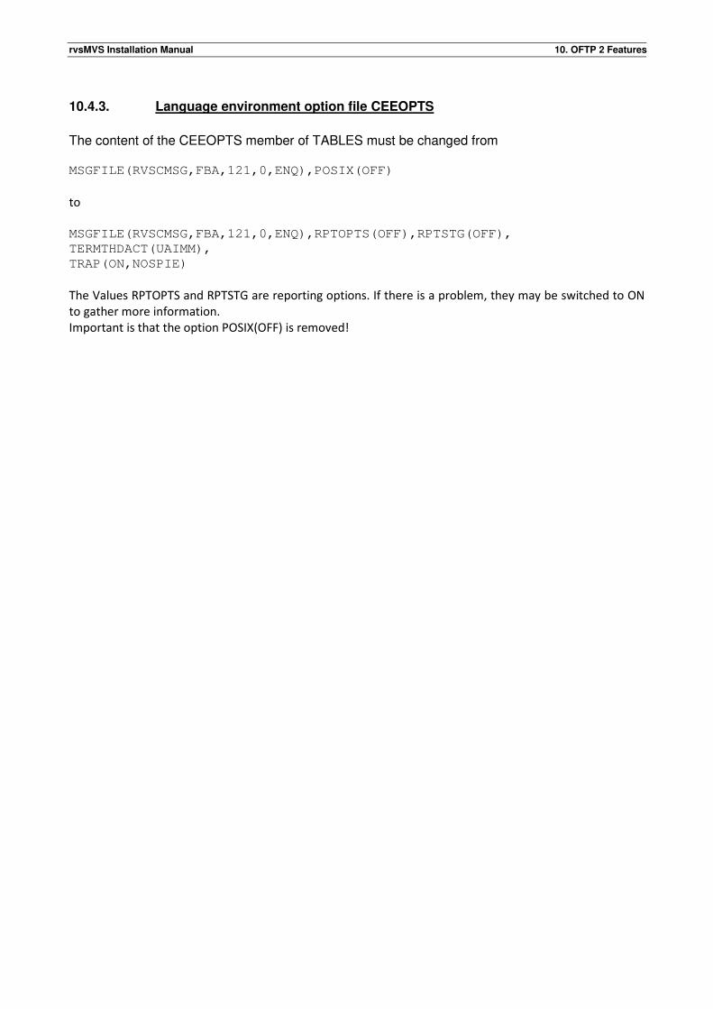
rvsMVS Installation Manual 10. OFTP 2 Features
10.4.3. Language environment option file CEEOPTS
The content of the CEEOPTS member of TABLES must be changed from MSGFILE(RVSCMSG,FBA,121,0,ENQ),POSIX(OFF)
to
MSGFILE(RVSCMSG,FBA,121,0,ENQ),RPTOPTS(OFF),RPTSTG(OFF),
TERMTHDACT(UAIMM),
TRAP(ON,NOSPIE)
The Values RPTOPTS and RPTSTG are reporting options. If there is a problem, they may be switched to ON
to gather more information.
Important is that the option POSIX(OFF) is removed!
rvsMVS Installation Manual 10. OFTP 2 Features
10.5. Configuration of the rvsMVS start procedure
In order to use OFTP2 Features it is necessary to adapt the rvsMVS start procedure. //CERTS DD DSN=RVS.CERTS, DISP=SHR This DD statement points to the certificate store. //KEYSTORE DD DSN=RVS.KEYSTORE, DISP=SHR This DD statement points to the key store. //CEEOPTS DD DSN=RVS.TABLES(CEEOPTS),DISP=SHR This DD statement points to the language environment option file, required by the security implementation. //RVSCMSG DD SYSOUT=* This DD statement is required for language environment messages. //EXTCONF DD DSN=RVS.TABLES(EXTCONF),DISP=SHR This DD statement points to an external configuration, used for special configuration of security tasks (for internal use, only)
10.6. System messages and error codes
Refer rvsMVS messages and codes.
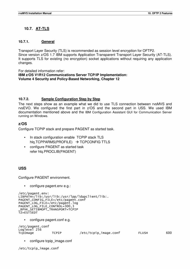
rvsMVS Installation Manual 10. OFTP 2 Features
10.7. AT-TLS
10.7.1. General
Transport Layer Security (TLS) is recommended as session level encryption for OFTP2. Since version z/OS 1.7 IBM supports Application Transparent Transport Layer Security (AT-TLS). It supports TLS for existing (no encryption) socket applications without requiring any application changes. For detailed information refer: IBM z/OS V1R12 Communications Server TCP/IP Implementation: Volume 4 Security and Policy-Based Networking, Chapter 12
10.7.2. Sample Configuration Step by Step
The next steps show as an example what we did to use TLS connection between rvsMVS and rvsEVO. We configured the first part in z/OS and the second part in USS. We used IBM documentation mentioned above and the IBM Configuration Assistant GUI for Communication Server running on Windows.
z/OS
Configure TCPIP stack and prepare PAGENT as started task.
• In stack configuration enable TCPIP stack TLS
hlq.TCPPARMS(PROFILE) � TCPCONFIG TTLS
• configure PAGENT as started task
refer hlq.PROCLIB(PAGENT)
USS
Configure PAGENT environment.
• configure pagent.env e.g.:
/etc/pagent.env: LIBPATH=/lib:/usr/lib:/usr/lpp/ldapclient/lib:. PAGENT_CONFIG_FILE=/etc/pagent.conf PAGENT_LOG_FILE=/etc/pagent.log PAGENT_LOG_FILE_CONTROL=300,3 _BPXK_SETIBMOPT_TRANSPORT=TCPIP TZ=EST5EDT
• configure pagent.conf e.g. /etc/pagent.conf Loglevel 256 TcpImage TCPIP /etc/tcpip_image.conf FLUSH 600
• configure tcpip_image.conf
/etc/tcpip_image.conf
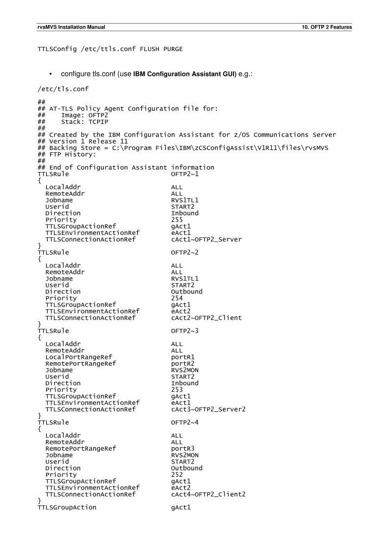
rvsMVS Installation Manual 10. OFTP 2 Features
TTLSConfig /etc/ttls.conf FLUSH PURGE
• configure tls.conf (use IBM Configuration Assistant GUI) e.g.: /etc/tls.conf ## ## AT-TLS Policy Agent Configuration file for: ## Image: OFTP2 ## Stack: TCPIP ## ## Created by the IBM Configuration Assistant for z/OS Communications Server ## Version 1 Release 11 ## Backing Store = C:\Program Files\IBM\zCSConfigAssist\V1R11\files\rvsMVS ## FTP History: ## ## End of Configuration Assistant information TTLSRule OFTP2~1 { LocalAddr ALL RemoteAddr ALL Jobname RVS1TL1 Userid START2 Direction Inbound Priority 255 TTLSGroupActionRef gAct1 TTLSEnvironmentActionRef eAct1 TTLSConnectionActionRef cAct1~OFTP2_Server } TTLSRule OFTP2~2 { LocalAddr ALL RemoteAddr ALL Jobname RVS1TL1 Userid START2 Direction Outbound Priority 254 TTLSGroupActionRef gAct1 TTLSEnvironmentActionRef eAct2 TTLSConnectionActionRef cAct2~OFTP2_Client } TTLSRule OFTP2~3 { LocalAddr ALL RemoteAddr ALL LocalPortRangeRef portR1 RemotePortRangeRef portR2 Jobname RVS2MON Userid START2 Direction Inbound Priority 253 TTLSGroupActionRef gAct1 TTLSEnvironmentActionRef eAct1 TTLSConnectionActionRef cAct3~OFTP2_Server2 } TTLSRule OFTP2~4 { LocalAddr ALL RemoteAddr ALL RemotePortRangeRef portR3 Jobname RVS2MON Userid START2 Direction Outbound Priority 252 TTLSGroupActionRef gAct1 TTLSEnvironmentActionRef eAct2 TTLSConnectionActionRef cAct4~OFTP2_Client2 } TTLSGroupAction gAct1
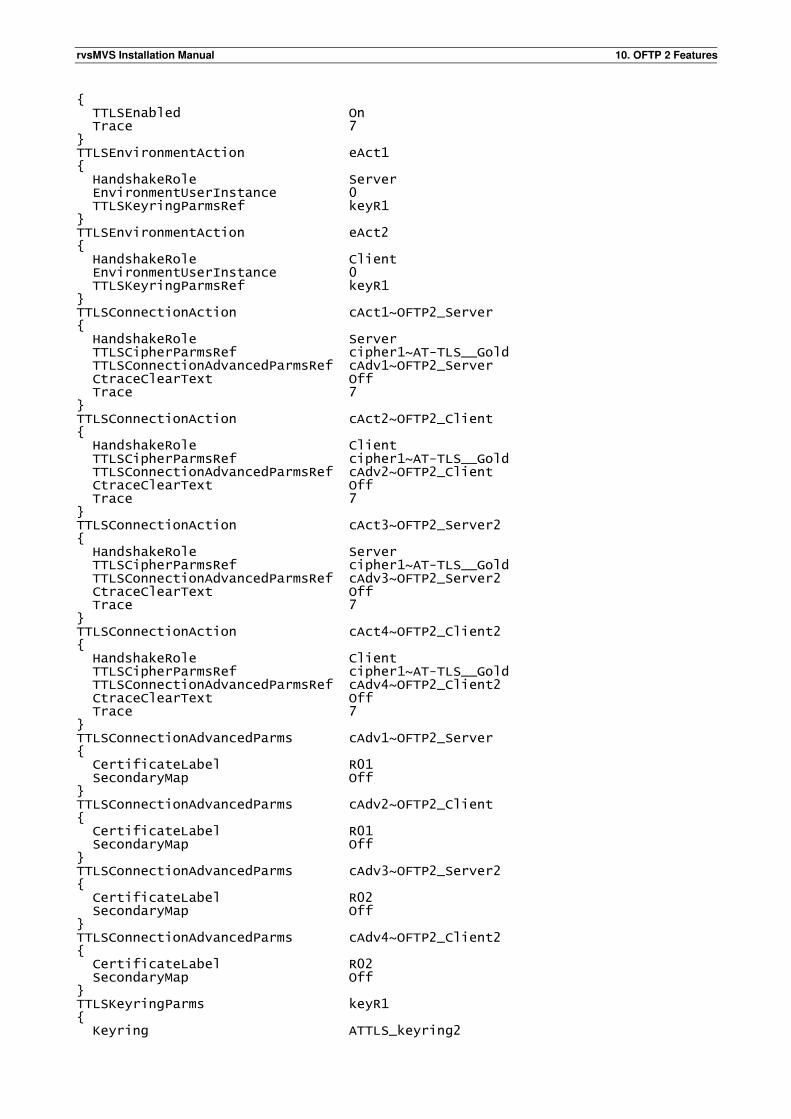
rvsMVS Installation Manual 10. OFTP 2 Features
{ TTLSEnabled On Trace 7 } TTLSEnvironmentAction eAct1 { HandshakeRole Server EnvironmentUserInstance 0 TTLSKeyringParmsRef keyR1 } TTLSEnvironmentAction eAct2 { HandshakeRole Client EnvironmentUserInstance 0 TTLSKeyringParmsRef keyR1 } TTLSConnectionAction cAct1~OFTP2_Server { HandshakeRole Server TTLSCipherParmsRef cipher1~AT-TLS__Gold TTLSConnectionAdvancedParmsRef cAdv1~OFTP2_Server CtraceClearText Off Trace 7 } TTLSConnectionAction cAct2~OFTP2_Client { HandshakeRole Client TTLSCipherParmsRef cipher1~AT-TLS__Gold TTLSConnectionAdvancedParmsRef cAdv2~OFTP2_Client CtraceClearText Off Trace 7 } TTLSConnectionAction cAct3~OFTP2_Server2 { HandshakeRole Server TTLSCipherParmsRef cipher1~AT-TLS__Gold TTLSConnectionAdvancedParmsRef cAdv3~OFTP2_Server2 CtraceClearText Off Trace 7 } TTLSConnectionAction cAct4~OFTP2_Client2 { HandshakeRole Client TTLSCipherParmsRef cipher1~AT-TLS__Gold TTLSConnectionAdvancedParmsRef cAdv4~OFTP2_Client2 CtraceClearText Off Trace 7 } TTLSConnectionAdvancedParms cAdv1~OFTP2_Server { CertificateLabel R01 SecondaryMap Off } TTLSConnectionAdvancedParms cAdv2~OFTP2_Client { CertificateLabel R01 SecondaryMap Off } TTLSConnectionAdvancedParms cAdv3~OFTP2_Server2 { CertificateLabel R02 SecondaryMap Off } TTLSConnectionAdvancedParms cAdv4~OFTP2_Client2 { CertificateLabel R02 SecondaryMap Off } TTLSKeyringParms keyR1 { Keyring ATTLS_keyring2
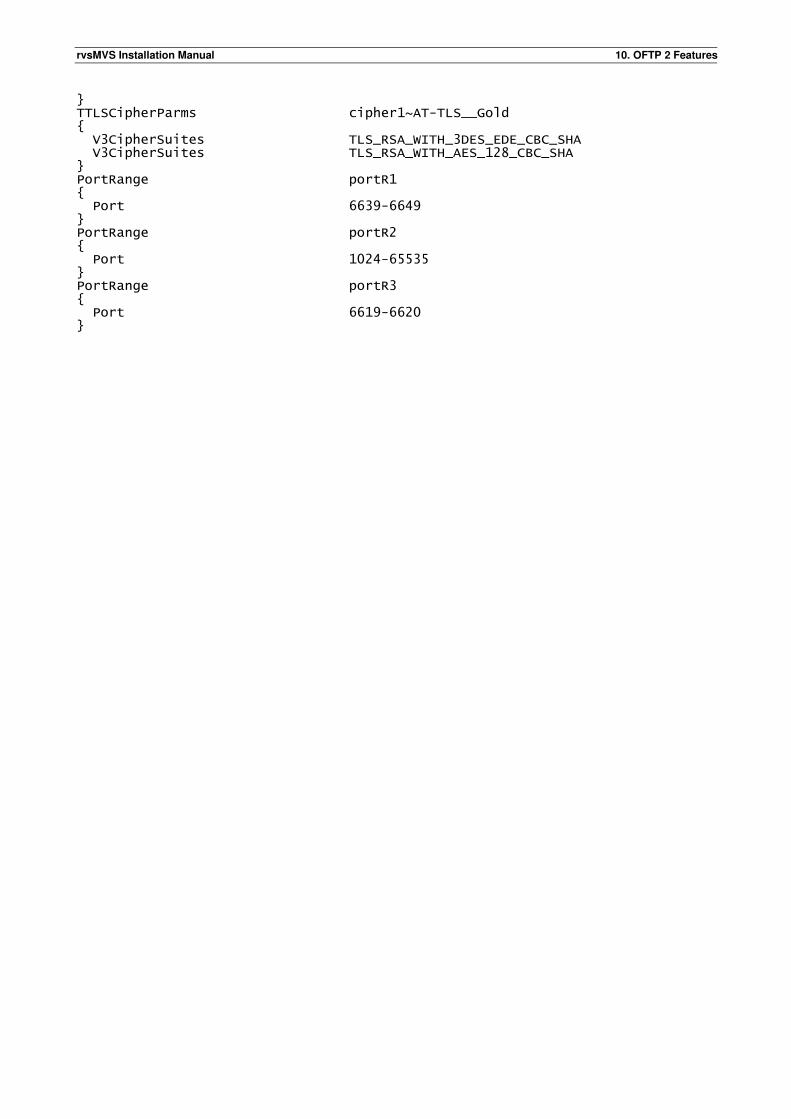
rvsMVS Installation Manual 10. OFTP 2 Features
} TTLSCipherParms cipher1~AT-TLS__Gold { V3CipherSuites TLS_RSA_WITH_3DES_EDE_CBC_SHA V3CipherSuites TLS_RSA_WITH_AES_128_CBC_SHA } PortRange portR1 { Port 6639-6649 } PortRange portR2 { Port 1024-65535 } PortRange portR3 { Port 6619-6620 }
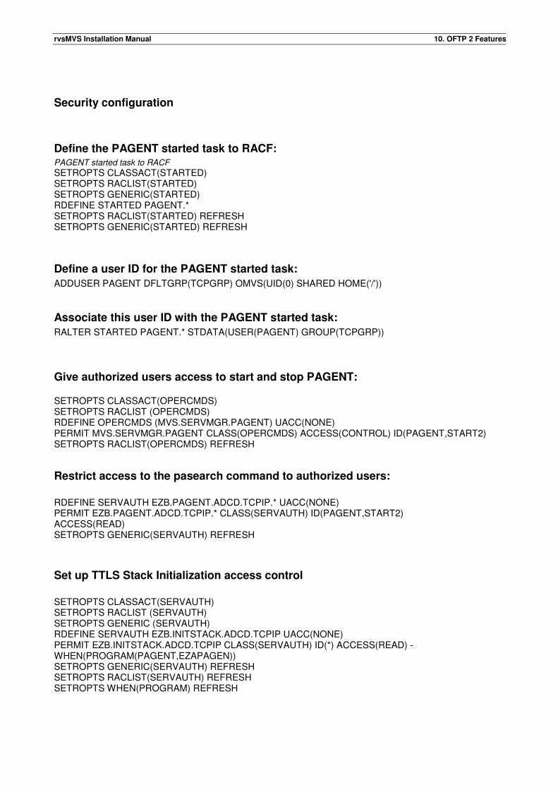
rvsMVS Installation Manual 10. OFTP 2 Features
Security configuration
Define the PAGENT started task to RACF: PAGENT started task to RACF
SETROPTS CLASSACT(STARTED) SETROPTS RACLIST(STARTED) SETROPTS GENERIC(STARTED) RDEFINE STARTED PAGENT.* SETROPTS RACLIST(STARTED) REFRESH SETROPTS GENERIC(STARTED) REFRESH
Define a user ID for the PAGENT started task:
ADDUSER PAGENT DFLTGRP(TCPGRP) OMVS(UID(0) SHARED HOME('/'))
Associate this user ID with the PAGENT started task:
RALTER STARTED PAGENT.* STDATA(USER(PAGENT) GROUP(TCPGRP))
Give authorized users access to start and stop PAGENT: SETROPTS CLASSACT(OPERCMDS) SETROPTS RACLIST (OPERCMDS) RDEFINE OPERCMDS (MVS.SERVMGR.PAGENT) UACC(NONE) PERMIT MVS.SERVMGR.PAGENT CLASS(OPERCMDS) ACCESS(CONTROL) ID(PAGENT,START2) SETROPTS RACLIST(OPERCMDS) REFRESH
Restrict access to the pasearch command to authorized users:
RDEFINE SERVAUTH EZB.PAGENT.ADCD.TCPIP.* UACC(NONE) PERMIT EZB.PAGENT.ADCD.TCPIP.* CLASS(SERVAUTH) ID(PAGENT,START2) ACCESS(READ) SETROPTS GENERIC(SERVAUTH) REFRESH
Set up TTLS Stack Initialization access control
SETROPTS CLASSACT(SERVAUTH) SETROPTS RACLIST (SERVAUTH) SETROPTS GENERIC (SERVAUTH) RDEFINE SERVAUTH EZB.INITSTACK.ADCD.TCPIP UACC(NONE) PERMIT EZB.INITSTACK.ADCD.TCPIP CLASS(SERVAUTH) ID(*) ACCESS(READ) - WHEN(PROGRAM(PAGENT,EZAPAGEN)) SETROPTS GENERIC(SERVAUTH) REFRESH SETROPTS RACLIST(SERVAUTH) REFRESH SETROPTS WHEN(PROGRAM) REFRESH
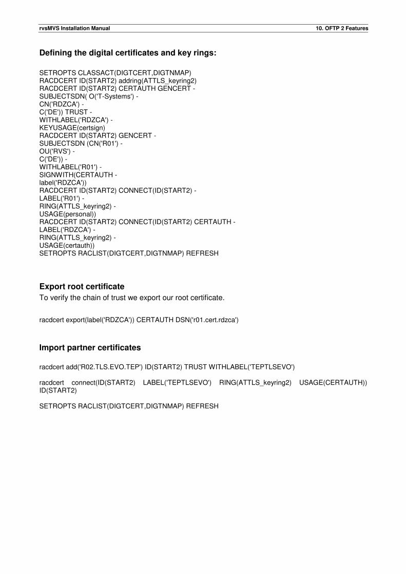
rvsMVS Installation Manual 10. OFTP 2 Features
Defining the digital certificates and key rings:
SETROPTS CLASSACT(DIGTCERT,DIGTNMAP) RACDCERT ID(START2) addring(ATTLS_keyring2) RACDCERT ID(START2) CERTAUTH GENCERT - SUBJECTSDN( O('T-Systems') - CN('RDZCA') - C('DE')) TRUST - WITHLABEL('RDZCA') - KEYUSAGE(certsign) RACDCERT ID(START2) GENCERT - SUBJECTSDN (CN('R01') - OU('RVS') - C('DE')) - WITHLABEL('R01') - SIGNWITH(CERTAUTH - label('RDZCA')) RACDCERT ID(START2) CONNECT(ID(START2) - LABEL('R01') - RING(ATTLS_keyring2) - USAGE(personal)) RACDCERT ID(START2) CONNECT(ID(START2) CERTAUTH - LABEL('RDZCA') - RING(ATTLS_keyring2) - USAGE(certauth)) SETROPTS RACLIST(DIGTCERT,DIGTNMAP) REFRESH
Export root certificate
To verify the chain of trust we export our root certificate.
racdcert export(label('RDZCA')) CERTAUTH DSN('r01.cert.rdzca')
Import partner certificates
racdcert add('R02.TLS.EVO.TEP') ID(START2) TRUST WITHLABEL('TEPTLSEVO') racdcert connect(ID(START2) LABEL('TEPTLSEVO') RING(ATTLS_keyring2) USAGE(CERTAUTH)) ID(START2) SETROPTS RACLIST(DIGTCERT,DIGTNMAP) REFRESH
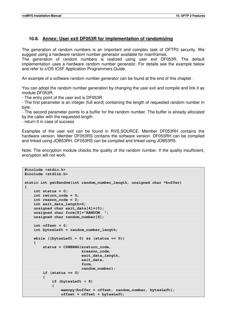
rvsMVS Installation Manual 10. OFTP 2 Features
10.8. Annex: User exit DF053R for implementation of randomizing
The generation of random numbers is an important and complex task of OFTP2 security. We suggest using a hardware random number generator available for mainframes. The generation of random numbers is realized using user exit DF053R. The default implementation uses a hardware random number generator. For details see the example below and refer to z/OS ICSF Application Programmers Guide. An example of a software random number generator can be found at the end of this chapter. You can adopt the random number generation by changing the user exit and compile and link it as module DF053R. - The entry point of the user exit is DF053R. - The first parameter is an integer (full word) containing the length of requested random number in byte. - The second parameter points to a buffer for the random number. The buffer is already allocated by the caller with the requested length. - return 0 in case of success Examples of the user exit can be found in RVS.SOURCE. Member DF053RH contains the hardware version. Member DF053RS contains the software version. DF053RH can be compiled and linked using JOB53RH. DF053RS can be compiled and linked using JOB53RS. Note: The encryption module checks the quality of the random number. If the quality insufficient, encryption will not work. #include <stdio.h>
#include <stdlib.h>
static int getRandom(int random_number_length, unsigned char *buffer)
{
int status = 0;
int return_code = 0;
int reason_code = 0;
int exit_data_length=0;
unsigned char exit_data[4]={0};
unsigned char form[8]="RANDOM ";
unsigned char random_number[8];
int offset = 0;
int bytesLeft = random_number_length;
while ((bytesLeft > 0) && (status == 0))
{
status = CSNBRNG(&return_code,
&reason_code,
exit_data_length,
exit_data,
form,
random_number);
if (status == 0)
{
if (bytesLeft < 8)
{
memcpy(buffer + offset, random_number, bytesLeft);
offset = offset + bytesLeft;
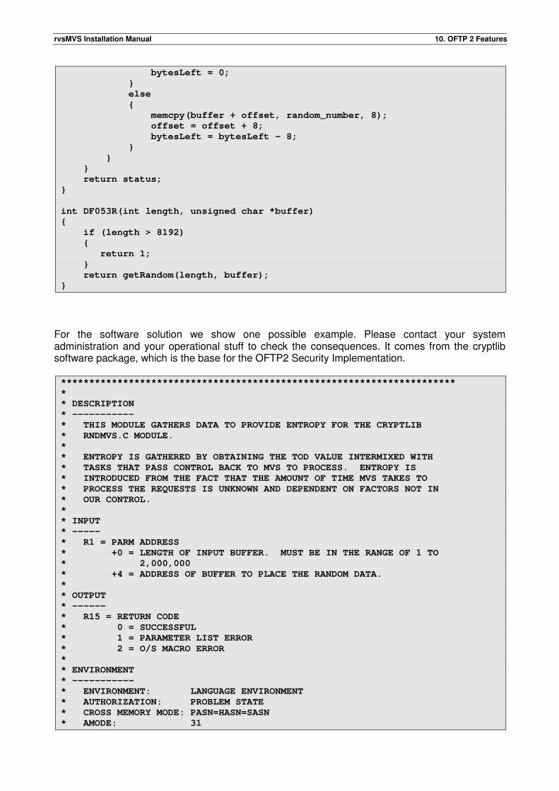
rvsMVS Installation Manual 10. OFTP 2 Features
bytesLeft = 0;
}
else
{
memcpy(buffer + offset, random_number, 8);
offset = offset + 8;
bytesLeft = bytesLeft - 8;
}
}
}
return status;
}
int DF053R(int length, unsigned char *buffer)
{
if (length > 8192)
{
return 1;
}
return getRandom(length, buffer);
}
For the software solution we show one possible example. Please contact your system administration and your operational stuff to check the consequences. It comes from the cryptlib software package, which is the base for the OFTP2 Security Implementation. **********************************************************************
*
* DESCRIPTION
* -----------
* THIS MODULE GATHERS DATA TO PROVIDE ENTROPY FOR THE CRYPTLIB
* RNDMVS.C MODULE.
*
* ENTROPY IS GATHERED BY OBTAINING THE TOD VALUE INTERMIXED WITH
* TASKS THAT PASS CONTROL BACK TO MVS TO PROCESS. ENTROPY IS
* INTRODUCED FROM THE FACT THAT THE AMOUNT OF TIME MVS TAKES TO
* PROCESS THE REQUESTS IS UNKNOWN AND DEPENDENT ON FACTORS NOT IN
* OUR CONTROL.
*
* INPUT
* -----
* R1 = PARM ADDRESS
* +0 = LENGTH OF INPUT BUFFER. MUST BE IN THE RANGE OF 1 TO
* 2,000,000
* +4 = ADDRESS OF BUFFER TO PLACE THE RANDOM DATA.
*
* OUTPUT
* ------
* R15 = RETURN CODE
* 0 = SUCCESSFUL
* 1 = PARAMETER LIST ERROR
* 2 = O/S MACRO ERROR
*
* ENVIRONMENT
* -----------
* ENVIRONMENT: LANGUAGE ENVIRONMENT
* AUTHORIZATION: PROBLEM STATE
* CROSS MEMORY MODE: PASN=HASN=SASN
* AMODE: 31
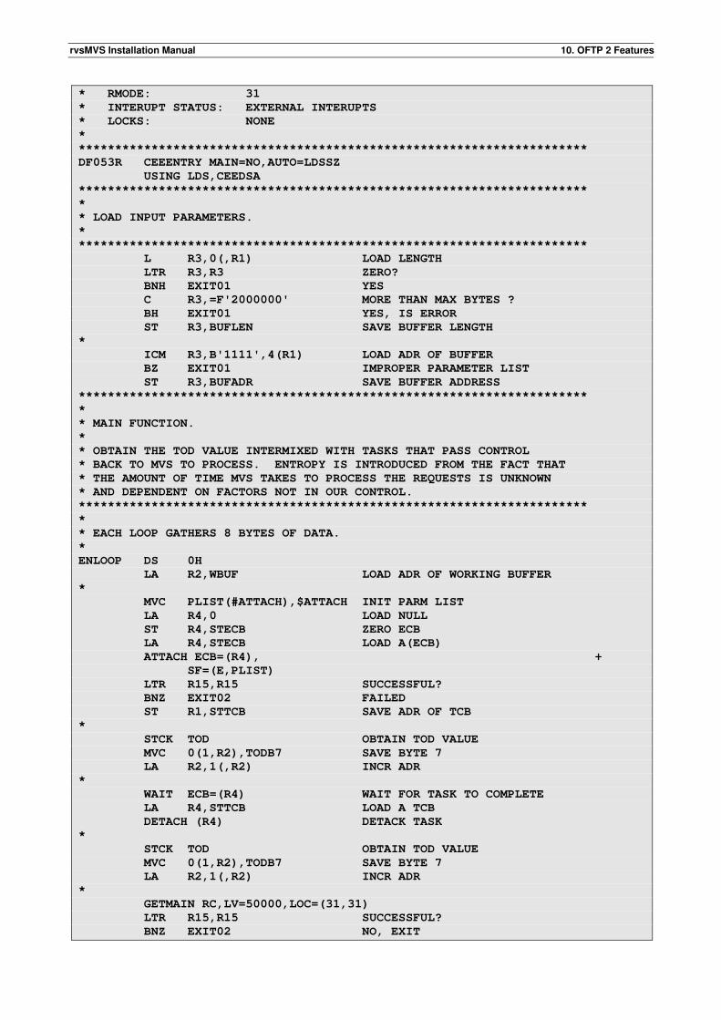
rvsMVS Installation Manual 10. OFTP 2 Features
* RMODE: 31
* INTERUPT STATUS: EXTERNAL INTERUPTS
* LOCKS: NONE
*
**********************************************************************
DF053R CEEENTRY MAIN=NO,AUTO=LDSSZ
USING LDS,CEEDSA
**********************************************************************
*
* LOAD INPUT PARAMETERS.
*
**********************************************************************
L R3,0(,R1) LOAD LENGTH
LTR R3,R3 ZERO?
BNH EXIT01 YES
C R3,=F'2000000' MORE THAN MAX BYTES ?
BH EXIT01 YES, IS ERROR
ST R3,BUFLEN SAVE BUFFER LENGTH
*
ICM R3,B'1111',4(R1) LOAD ADR OF BUFFER
BZ EXIT01 IMPROPER PARAMETER LIST
ST R3,BUFADR SAVE BUFFER ADDRESS
**********************************************************************
*
* MAIN FUNCTION.
*
* OBTAIN THE TOD VALUE INTERMIXED WITH TASKS THAT PASS CONTROL
* BACK TO MVS TO PROCESS. ENTROPY IS INTRODUCED FROM THE FACT THAT
* THE AMOUNT OF TIME MVS TAKES TO PROCESS THE REQUESTS IS UNKNOWN
* AND DEPENDENT ON FACTORS NOT IN OUR CONTROL.
**********************************************************************
*
* EACH LOOP GATHERS 8 BYTES OF DATA.
*
ENLOOP DS 0H
LA R2,WBUF LOAD ADR OF WORKING BUFFER
*
MVC PLIST(#ATTACH),$ATTACH INIT PARM LIST
LA R4,0 LOAD NULL
ST R4,STECB ZERO ECB
LA R4,STECB LOAD A(ECB)
ATTACH ECB=(R4), +
SF=(E,PLIST)
LTR R15,R15 SUCCESSFUL?
BNZ EXIT02 FAILED
ST R1,STTCB SAVE ADR OF TCB
*
STCK TOD OBTAIN TOD VALUE
MVC 0(1,R2),TODB7 SAVE BYTE 7
LA R2,1(,R2) INCR ADR
*
WAIT ECB=(R4) WAIT FOR TASK TO COMPLETE
LA R4,STTCB LOAD A TCB
DETACH (R4) DETACK TASK
*
STCK TOD OBTAIN TOD VALUE
MVC 0(1,R2),TODB7 SAVE BYTE 7
LA R2,1(,R2) INCR ADR
*
GETMAIN RC,LV=50000,LOC=(31,31)
LTR R15,R15 SUCCESSFUL?
BNZ EXIT02 NO, EXIT
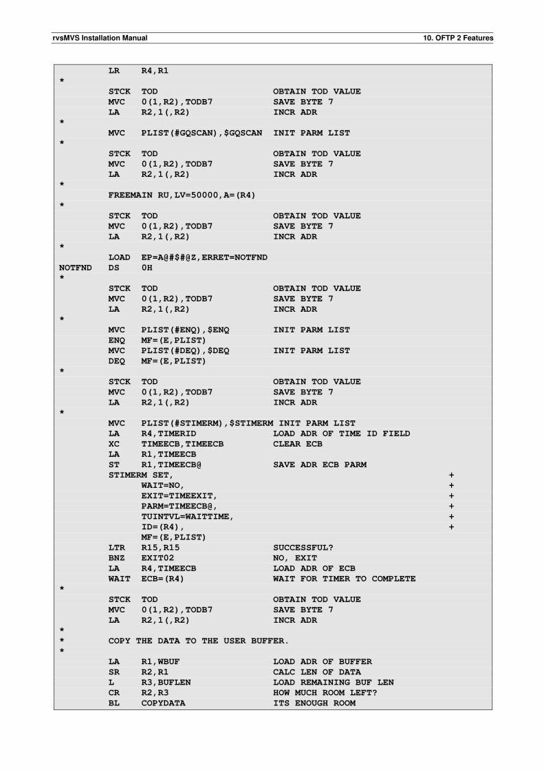
rvsMVS Installation Manual 10. OFTP 2 Features
LR R4,R1
*
STCK TOD OBTAIN TOD VALUE
MVC 0(1,R2),TODB7 SAVE BYTE 7
LA R2,1(,R2) INCR ADR
*
MVC PLIST(#GQSCAN),$GQSCAN INIT PARM LIST
*
STCK TOD OBTAIN TOD VALUE
MVC 0(1,R2),TODB7 SAVE BYTE 7
LA R2,1(,R2) INCR ADR
*
FREEMAIN RU,LV=50000,A=(R4)
*
STCK TOD OBTAIN TOD VALUE
MVC 0(1,R2),TODB7 SAVE BYTE 7
LA R2,1(,R2) INCR ADR
*
LOAD EP=A@#$#@Z,ERRET=NOTFND
NOTFND DS 0H
*
STCK TOD OBTAIN TOD VALUE
MVC 0(1,R2),TODB7 SAVE BYTE 7
LA R2,1(,R2) INCR ADR
*
MVC PLIST(#ENQ),$ENQ INIT PARM LIST
ENQ MF=(E,PLIST)
MVC PLIST(#DEQ),$DEQ INIT PARM LIST
DEQ MF=(E,PLIST)
*
STCK TOD OBTAIN TOD VALUE
MVC 0(1,R2),TODB7 SAVE BYTE 7
LA R2,1(,R2) INCR ADR
*
MVC PLIST(#STIMERM),$STIMERM INIT PARM LIST
LA R4,TIMERID LOAD ADR OF TIME ID FIELD
XC TIMEECB,TIMEECB CLEAR ECB
LA R1,TIMEECB
ST R1,TIMEECB@ SAVE ADR ECB PARM
STIMERM SET, +
WAIT=NO, +
EXIT=TIMEEXIT, +
PARM=TIMEECB@, +
TUINTVL=WAITTIME, +
ID=(R4), +
MF=(E,PLIST)
LTR R15,R15 SUCCESSFUL?
BNZ EXIT02 NO, EXIT
LA R4,TIMEECB LOAD ADR OF ECB
WAIT ECB=(R4) WAIT FOR TIMER TO COMPLETE
*
STCK TOD OBTAIN TOD VALUE
MVC 0(1,R2),TODB7 SAVE BYTE 7
LA R2,1(,R2) INCR ADR
*
* COPY THE DATA TO THE USER BUFFER.
*
LA R1,WBUF LOAD ADR OF BUFFER
SR R2,R1 CALC LEN OF DATA
L R3,BUFLEN LOAD REMAINING BUF LEN
CR R2,R3 HOW MUCH ROOM LEFT?
BL COPYDATA ITS ENOUGH ROOM
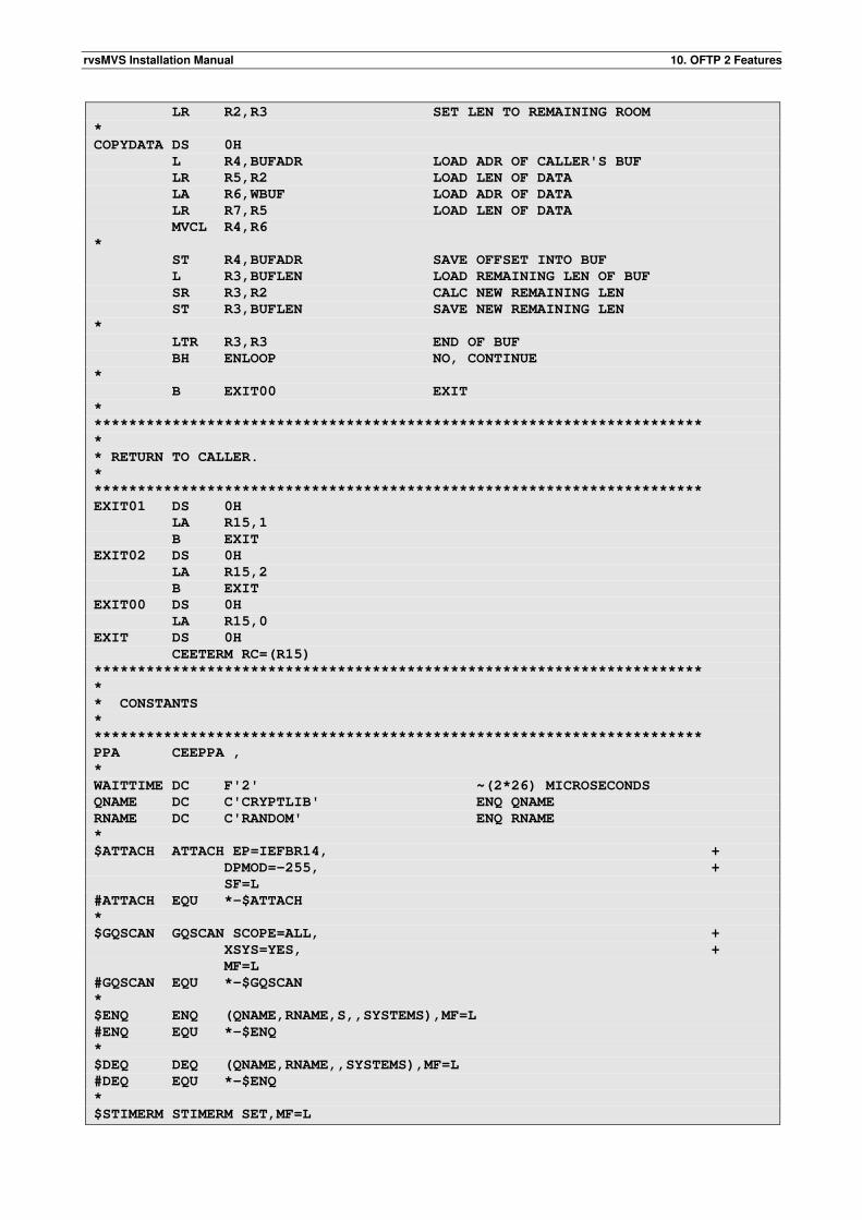
rvsMVS Installation Manual 10. OFTP 2 Features
LR R2,R3 SET LEN TO REMAINING ROOM
*
COPYDATA DS 0H
L R4,BUFADR LOAD ADR OF CALLER'S BUF
LR R5,R2 LOAD LEN OF DATA
LA R6,WBUF LOAD ADR OF DATA
LR R7,R5 LOAD LEN OF DATA
MVCL R4,R6
*
ST R4,BUFADR SAVE OFFSET INTO BUF
L R3,BUFLEN LOAD REMAINING LEN OF BUF
SR R3,R2 CALC NEW REMAINING LEN
ST R3,BUFLEN SAVE NEW REMAINING LEN
*
LTR R3,R3 END OF BUF
BH ENLOOP NO, CONTINUE
*
B EXIT00 EXIT
*
**********************************************************************
*
* RETURN TO CALLER.
*
**********************************************************************
EXIT01 DS 0H
LA R15,1
B EXIT
EXIT02 DS 0H
LA R15,2
B EXIT
EXIT00 DS 0H
LA R15,0
EXIT DS 0H
CEETERM RC=(R15)
**********************************************************************
*
* CONSTANTS
*
**********************************************************************
PPA CEEPPA ,
*
WAITTIME DC F'2' ~(2*26) MICROSECONDS
QNAME DC C'CRYPTLIB' ENQ QNAME
RNAME DC C'RANDOM' ENQ RNAME
*
$ATTACH ATTACH EP=IEFBR14, +
DPMOD=-255, +
SF=L
#ATTACH EQU *-$ATTACH
*
$GQSCAN GQSCAN SCOPE=ALL, +
XSYS=YES, +
MF=L
#GQSCAN EQU *-$GQSCAN
*
$ENQ ENQ (QNAME,RNAME,S,,SYSTEMS),MF=L
#ENQ EQU *-$ENQ
*
$DEQ DEQ (QNAME,RNAME,,SYSTEMS),MF=L
#DEQ EQU *-$ENQ
*
$STIMERM STIMERM SET,MF=L
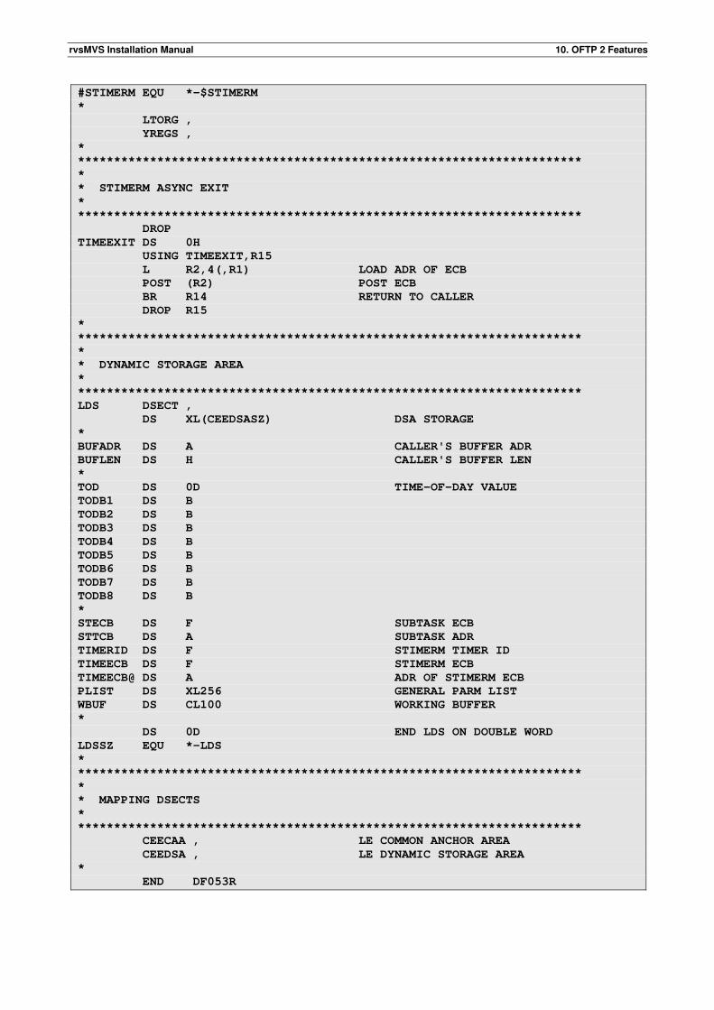
rvsMVS Installation Manual 10. OFTP 2 Features
#STIMERM EQU *-$STIMERM
*
LTORG ,
YREGS ,
*
**********************************************************************
*
* STIMERM ASYNC EXIT
*
**********************************************************************
DROP
TIMEEXIT DS 0H
USING TIMEEXIT,R15
L R2,4(,R1) LOAD ADR OF ECB
POST (R2) POST ECB
BR R14 RETURN TO CALLER
DROP R15
*
**********************************************************************
*
* DYNAMIC STORAGE AREA
*
**********************************************************************
LDS DSECT ,
DS XL(CEEDSASZ) DSA STORAGE
*
BUFADR DS A CALLER'S BUFFER ADR
BUFLEN DS H CALLER'S BUFFER LEN
*
TOD DS 0D TIME-OF-DAY VALUE
TODB1 DS B
TODB2 DS B
TODB3 DS B
TODB4 DS B
TODB5 DS B
TODB6 DS B
TODB7 DS B
TODB8 DS B
*
STECB DS F SUBTASK ECB
STTCB DS A SUBTASK ADR
TIMERID DS F STIMERM TIMER ID
TIMEECB DS F STIMERM ECB
TIMEECB@ DS A ADR OF STIMERM ECB
PLIST DS XL256 GENERAL PARM LIST
WBUF DS CL100 WORKING BUFFER
*
DS 0D END LDS ON DOUBLE WORD
LDSSZ EQU *-LDS
*
**********************************************************************
*
* MAPPING DSECTS
*
**********************************************************************
CEECAA , LE COMMON ANCHOR AREA
CEEDSA , LE DYNAMIC STORAGE AREA
*
END DF053R
rvsMVS Installation Manual 10. OFTP 2 Features
This page will be intentionally empty.
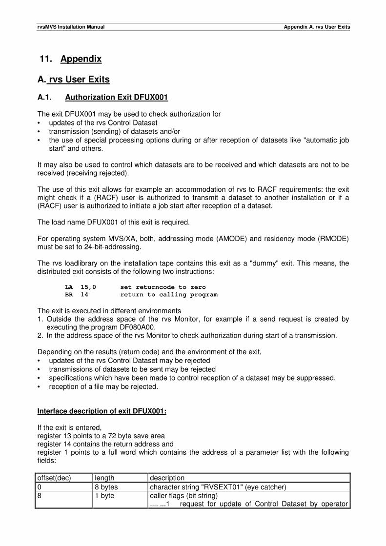
rvsMVS Installation Manual Appendix A. rvs User Exits
11. Appendix
A. rvs User Exits
A.1. Authorization Exit DFUX001 The exit DFUX001 may be used to check authorization for • updates of the rvs Control Dataset • transmission (sending) of datasets and/or • the use of special processing options during or after reception of datasets like "automatic job
start" and others. It may also be used to control which datasets are to be received and which datasets are not to be received (receiving rejected). The use of this exit allows for example an accommodation of rvs to RACF requirements: the exit might check if a (RACF) user is authorized to transmit a dataset to another installation or if a (RACF) user is authorized to initiate a job start after reception of a dataset. The load name DFUX001 of this exit is required. For operating system MVS/XA, both, addressing mode (AMODE) and residency mode (RMODE) must be set to 24-bit-addressing. The rvs loadlibrary on the installation tape contains this exit as a "dummy" exit. This means, the distributed exit consists of the following two instructions:
LA 15,0 set returncode to zero
BR 14 return to calling program
The exit is executed in different environments 1. Outside the address space of the rvs Monitor, for example if a send request is created by
executing the program DF080A00. 2. In the address space of the rvs Monitor to check authorization during start of a transmission. Depending on the results (return code) and the environment of the exit, • updates of the rvs Control Dataset may be rejected • transmissions of datasets to be sent may be rejected • specifications which have been made to control reception of a dataset may be suppressed. • reception of a file may be rejected. Interface description of exit DFUX001: If the exit is entered, register 13 points to a 72 byte save area register 14 contains the return address and register 1 points to a full word which contains the address of a parameter list with the following fields:
offset(dec) length description
0 8 bytes character string "RVSEXT01" (eye catcher) 8 1 byte caller flags (bit string)
.... ...1 request for update of Control Dataset by operator
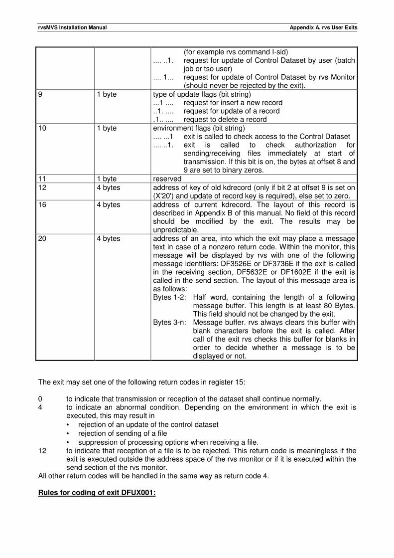
rvsMVS Installation Manual Appendix A. rvs User Exits
(for example rvs command I-sid) .... ..1. request for update of Control Dataset by user (batch
job or tso user) .... 1... request for update of Control Dataset by rvs Monitor
(should never be rejected by the exit). 9 1 byte type of update flags (bit string)
...1 .... request for insert a new record
..1. .... request for update of a record
.1.. .... request to delete a record 10 1 byte environment flags (bit string)
.... ...1 exit is called to check access to the Control Dataset
.... ..1. exit is called to check authorization for sending/receiving files immediately at start of transmission. If this bit is on, the bytes at offset 8 and 9 are set to binary zeros.
11 1 byte reserved 12 4 bytes address of key of old kdrecord (only if bit 2 at offset 9 is set on
(X'20') and update of record key is required), else set to zero. 16 4 bytes address of current kdrecord. The layout of this record is
described in Appendix B of this manual. No field of this record should be modified by the exit. The results may be unpredictable.
20 4 bytes address of an area, into which the exit may place a message text in case of a nonzero return code. Within the monitor, this message will be displayed by rvs with one of the following message identifiers: DF3526E or DF3736E if the exit is called in the receiving section, DF5632E or DF1602E if the exit is called in the send section. The layout of this message area is as follows: Bytes 1-2: Half word, containing the length of a following
message buffer. This length is at least 80 Bytes. This field should not be changed by the exit.
Bytes 3-n: Message buffer. rvs always clears this buffer with blank characters before the exit is called. After call of the exit rvs checks this buffer for blanks in order to decide whether a message is to be displayed or not.
The exit may set one of the following return codes in register 15: 0 to indicate that transmission or reception of the dataset shall continue normally. 4 to indicate an abnormal condition. Depending on the environment in which the exit is
executed, this may result in • rejection of an update of the control dataset • rejection of sending of a file • suppression of processing options when receiving a file.
12 to indicate that reception of a file is to be rejected. This return code is meaningless if the exit is executed outside the address space of the rvs monitor or if it is executed within the send section of the rvs monitor.
All other return codes will be handled in the same way as return code 4. Rules for coding of exit DFUX001:
rvsMVS Installation Manual Appendix A. rvs User Exits
This exit must be coded reusable or reentrant. The exit must restore the contents of registers 2 - 13 when returning control to the calling rvs program. The exit should not modify • any field of the current record of the rvs Control Dataset ("KDRECORD") • the length field of the message buffer. The following logic (send or receive section) applies to • each active send session (rvs-SNA session) • each active leased line (BTAM/BSC) • each active switched line (BTAM/BSC) after establishing line connection to a remote rvs
station. • each active switched virtual circuit (SVC) to a remote rvs station. "Active" here always means
that the line (or session) has been activated within the rvs monitor.
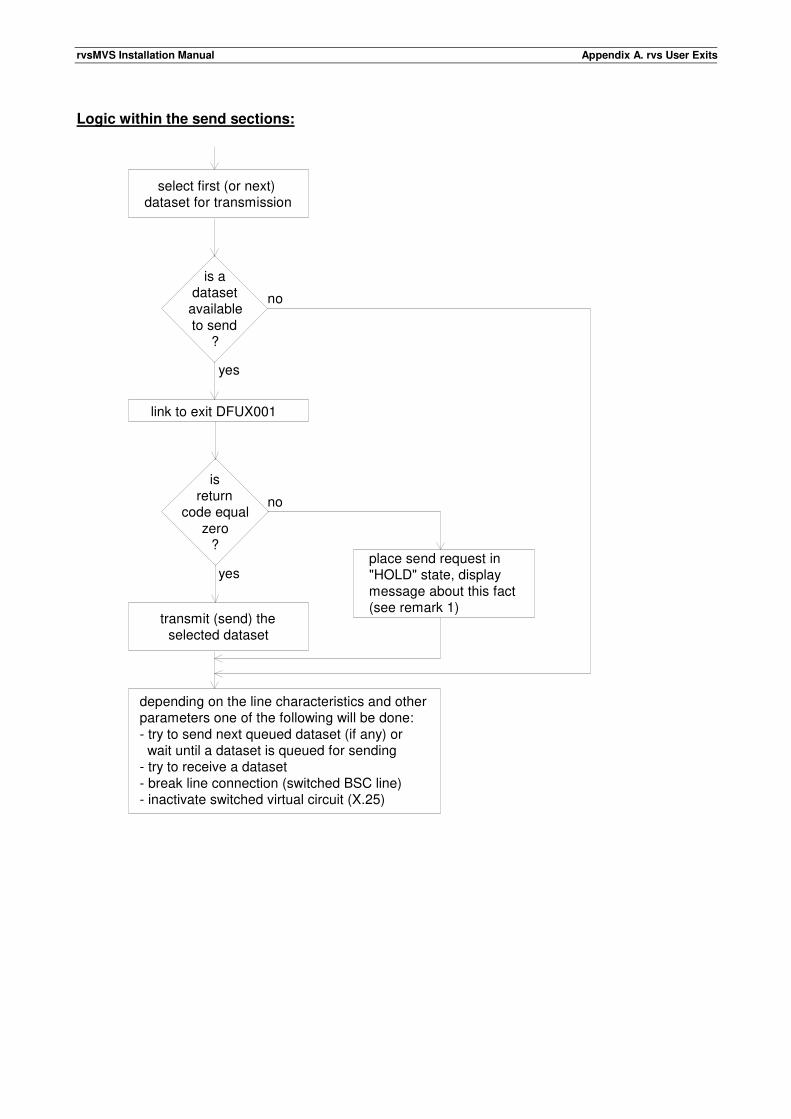
rvsMVS Installation Manual Appendix A. rvs User Exits
Logic within the send sections:
select first (or next)dataset for transmission
link to exit DFUX001
transmit (send) theselected dataset
is a dataset
availableto send
?
isreturn
code equalzero
?place send request in"HOLD" state, displaymessage about this fact(see remark 1)
depending on the line characteristics and otherparameters one of the following will be done:- try to send next queued dataset (if any) or wait until a dataset is queued for sending- try to receive a dataset- break line connection (switched BSC line)- inactivate switched virtual circuit (X.25)
yes
no
no
yes
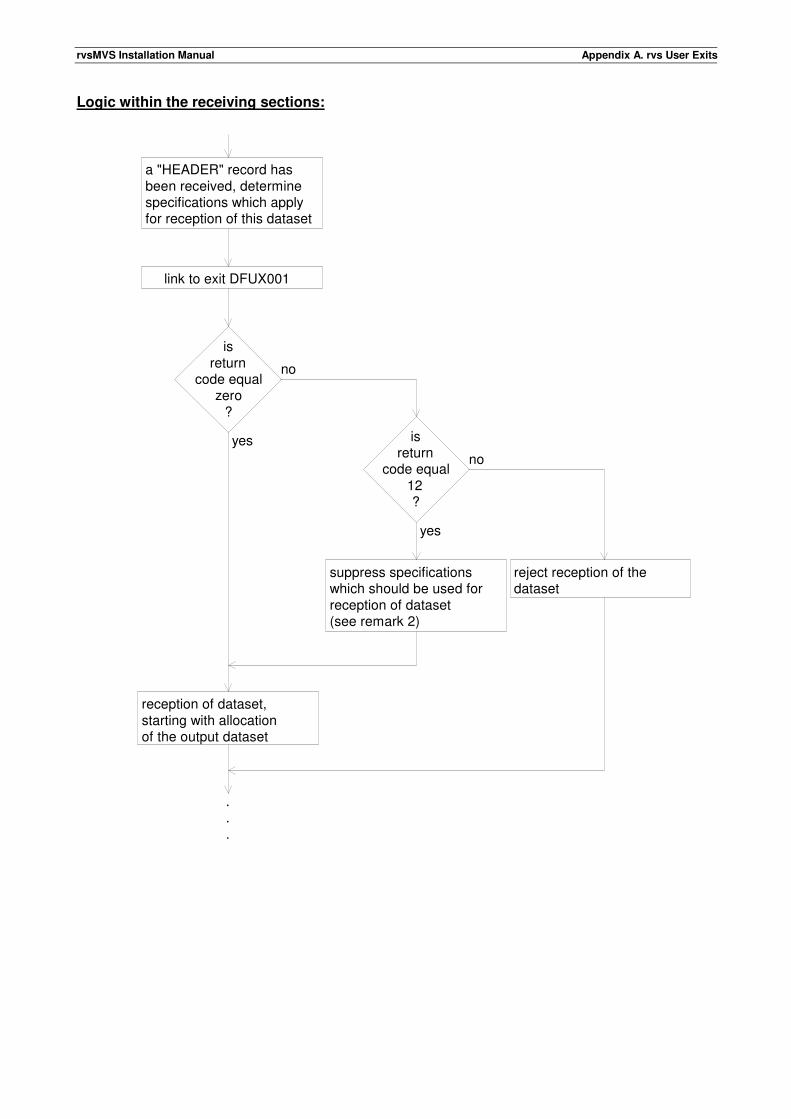
rvsMVS Installation Manual Appendix A. rvs User Exits
Logic within the receiving sections:
a "HEADER" record hasbeen received, determinespecifications which applyfor reception of this dataset
link to exit DFUX001
isreturn
code equalzero
?
suppress specifications which should be used forreception of dataset(see remark 2)
reception of dataset, starting with allocationof the output dataset
yes
no
no
yes
isreturn
code equal12?
reject reception of thedataset
.
.
.
rvsMVS Installation Manual Appendix A. rvs User Exits
Remarks: 1) If the exit returns control to rvs with a nonzero return code, the send request (a record of
type "AS" within the rvs Control Dataset) will be placed in "HOLD" state. This means, the send request will not be accessed by rvs until the rvs command "S sid" has been entered for this request.
2) Specifications for reception include such things as automatic job start, rename function or
the use of a special disk volume (unit group) to store the received dataset. If the exit returns control to rvs with return code 4 or 8, all such specifications (done during creation of a "resident receive entry" in the receiving station or done during creation of the send request (by specifying "remote options") in the sending station) will be ignored by RVS. Receiving of the dataset will be performed as if • no "resident receive entry" exists for this dataset and • no "remote options" have been specified when the dataset was queued for sending in
the sending station. Instead of these specifications, (installation dependent) default values will be taken. If the received dataset contains job control which is to be submitted (RJE function), rvs will perform this function independent of the exit return code. rvs will suppress this only if the definition of the remote station within the rvs stations table excludes the RJE function (see Installation Manual, definition of the station table. If the exit returns control to rvs with return code 12 within the receiving section, reception of the file will be rejected. If the exit returns control to rvs with return code 12 outside the receiving section, rvs will act in the same way as described for return code 4.
rvs will always display a nonzero return code of exit DFUX001 by writing a message to the console. Remarks about the use of different KDRECORD fields: Fields of special interest if the exit is called within the send sections of the rvs monitor or if it is called during creation of a send request outside the address space of the monitor (value of KDRECTYP: =C'AS') (see also Appendix B of this manual): KDREMOTE same value as KDFINAL KDDSN dataset name used as reference between sender and receiver KDDSNNEW physical dataset name KDUSERID job name or TSO userid, which created this record (send request) KDRUSER RACF userid of the above job (TSO-session), if RACF is installed (else blank) If the exit is called within the receive sections of the rvs monitor (value of KDRECTYP: =C'AR') or if it is called during creation of a resident receive entry outside the address space of the monitor (value of KDRECTYP: =C'RR'), the following fields are important in each case: KDREMOTE, KDDSN and KDDSNNEW There are four groups of other fields, which may be of interest: 1. Sysout specifications, indicated by a nonblank field KDSYSOUT.
This group includes KDSYSOUT, KDPROG, KDFORM, KDCOPIES and KDDEST. Sysout specifications may have been done in the receiving station by creating a resident receive entry (indicated by bit KDRESREC of field KDBITS3) or in the sending station (if bit KDRESREC is set off). If sysout parameters are specified in the sending station, a resident receive entry in the receiving station will be ignored by RVS.
rvsMVS Installation Manual Appendix A. rvs User Exits
2. Remote options specified in the sending station (indicated by bit KDRMTOPT in field
KDBITS2) This group includes KDVOLNRR, KDSUNIT, KDDEVR, KDDISPR and KDBITSR1. If remote options are specified in the sending station and this station is authorized for this (see Installation Manual, definition of the stations table), a resident receive entry in the receiving station will be ignored by rvs.
3. Specifications within a resident receive entry (indicated by bit KDRESREC in field
KDBITS3).
This group includes KDDEVTYP, KDSUNIT, KDVOLNRD, KDDISP, KDJOBDSN, KDJOB, KDUSERID, KDRUSER and all fields of group 1. Automatic job start after reception of a dataset is indicated by a nonblank field KDJOB. If the field KDJOBDSN does not contain the name of a PDS, the name of the central rvs job dataset is valid (the central job dataset is allocated to the rvs Monitor with the ddname RVSJOBS, see Installation Manual, description of the rvs Start Procedure). Fields KDUSERID and KDRUSER contain the values which have been taken from the job (TSO session) during creation of the resident receive entry. These fields may be blank if the resident receive entry had been created in earlier rvs releases than rvs-OS Release 3.2.
4. User fields KDEXTFLD, KDUSER.
The content of these fields is transmitted from sender to receiver of the file. So these fields may be used for communication between exits within sending and receiving station. Field KDEXTFLD is used by the SNA- and BSC components, field KDUSER is used by the X25 component (ODETTE FILE TRANSFER PROTOCOL). This explains the different length of the fields. If KDEXTFLD is filled with data in the sending station, field KDEXTTYP should be set to character "E".
Example of exit DFUX001: An example of DFUX001 is located on the rvsMVS installation tape in the rvs source library (2. file). Please refer to this example in case of need of adaptation to your environment. A.2. rvsWIN Exit DFUX002 The exit DFUX002 may be used to check authorization for access of rvsWIN users to rvsMVS. The use of this exit allows for example an accommodation of rvs to RACF requirements: the exit might check if an rvsWIN user using an RACF userid is authorized to get access to the rvsMVS on the host. The loadname DFUX002 of this exit is required. For operating system MVS/XA, both, addressing mode (AMODE) and residency mode (RMODE) must be set to 24-bit-addressing.
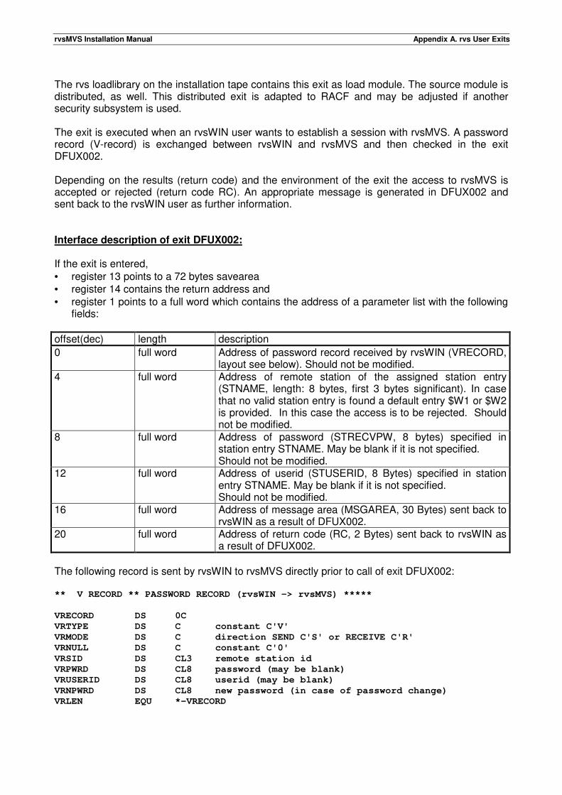
rvsMVS Installation Manual Appendix A. rvs User Exits
The rvs loadlibrary on the installation tape contains this exit as load module. The source module is distributed, as well. This distributed exit is adapted to RACF and may be adjusted if another security subsystem is used. The exit is executed when an rvsWIN user wants to establish a session with rvsMVS. A password record (V-record) is exchanged between rvsWIN and rvsMVS and then checked in the exit DFUX002. Depending on the results (return code) and the environment of the exit the access to rvsMVS is accepted or rejected (return code RC). An appropriate message is generated in DFUX002 and sent back to the rvsWIN user as further information. Interface description of exit DFUX002: If the exit is entered, • register 13 points to a 72 bytes savearea • register 14 contains the return address and • register 1 points to a full word which contains the address of a parameter list with the following
fields:
offset(dec) length description
0 full word Address of password record received by rvsWIN (VRECORD, layout see below). Should not be modified.
4 full word Address of remote station of the assigned station entry (STNAME, length: 8 bytes, first 3 bytes significant). In case that no valid station entry is found a default entry $W1 or $W2 is provided. In this case the access is to be rejected. Should not be modified.
8 full word Address of password (STRECVPW, 8 bytes) specified in station entry STNAME. May be blank if it is not specified. Should not be modified.
12 full word Address of userid (STUSERID, 8 Bytes) specified in station entry STNAME. May be blank if it is not specified. Should not be modified.
16 full word Address of message area (MSGAREA, 30 Bytes) sent back to rvsWIN as a result of DFUX002.
20 full word Address of return code (RC, 2 Bytes) sent back to rvsWIN as a result of DFUX002.
The following record is sent by rvsWIN to rvsMVS directly prior to call of exit DFUX002: ** V RECORD ** PASSWORD RECORD (rvsWIN -> rvsMVS) *****
VRECORD DS 0C
VRTYPE DS C constant C'V'
VRMODE DS C direction SEND C'S' or RECEIVE C'R'
VRNULL DS C constant C'0'
VRSID DS CL3 remote station id
VRPWRD DS CL8 password (may be blank)
VRUSERID DS CL8 userid (may be blank)
VRNPWRD DS CL8 new password (in case of password change)
VRLEN EQU *-VRECORD
rvsMVS Installation Manual Appendix A. rvs User Exits
At least one of both fields VRPWRD and VRUSERID must be specified by the rvsWIN user, otherwise, the access is to be rejected by DFUX002. The exit may set one of the following return codes in field RC: 0 to indicate that access to rvsMVS is accepted All other return codes indicating that the access is rejected. All return codes must be accompanied by a message in field MSGAREA. This message is sent back to rvsWIN and displayed on the screen. Rules for coding of exit DFUX002: This exit must be coded reusable or reentrant. The exit must restore the contents of registers 2 - 13 when returning control to the calling rvs program. Example of exit DFUX002: An example of DFUX002 is found on the rvsMVS installation tape in the rvs source library (2. file). Please refer to this example in case of need of adaption to your environment. An example of a station table entry for rvsWIN is specified in Chapter 6.2.2, SNA Stations, parameter TYPE=WIN-3270. A.3. Accounting User Exit The accounting user exit may be used to obtain data about all executed transmissions in order to process these data for reasons of accounting (or other reasons, for example statistics). This exit is called by the rvs monitor if the start parameter "ACEXIT=name" has been specified, see chapter 6.1. For operating system MVS/XA, both, addressing mode (AMODE) and residency mode (RMODE) must be set to 24-bit-addressing. If installed, the exit is given control • just after start of the rvs monitor (without any accounting information), • after each transmission of a dataset (send or receive), independent of the fact whether the
transmission ended normally or not, • just before stop of the rvs monitor (without any accounting information). Interface description of the exit: If the exit is entered, • register 13 points to a 72 byte savearea • register 14 contains the return address and • register 1 contains the address of a parameter list with the following fields:
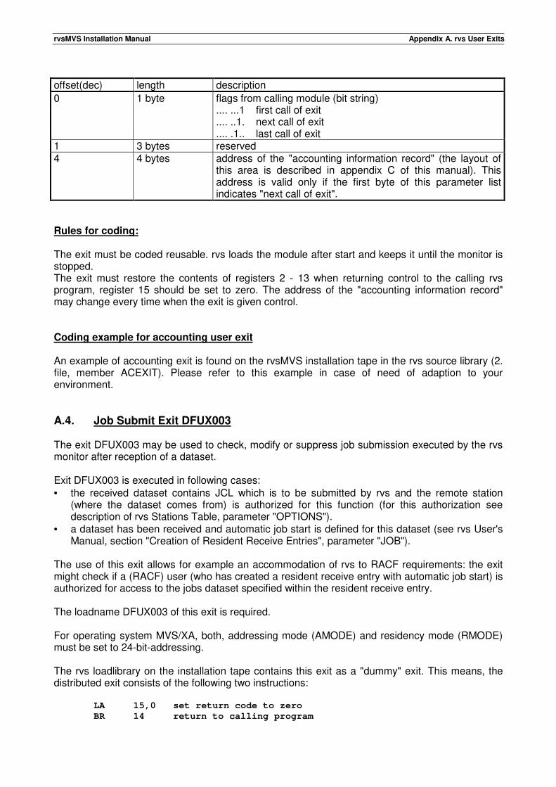
rvsMVS Installation Manual Appendix A. rvs User Exits
offset(dec) length description
0 1 byte flags from calling module (bit string) .... ...1 first call of exit .... ..1. next call of exit .... .1.. last call of exit
1 3 bytes reserved 4 4 bytes address of the "accounting information record" (the layout of
this area is described in appendix C of this manual). This address is valid only if the first byte of this parameter list indicates "next call of exit".
Rules for coding: The exit must be coded reusable. rvs loads the module after start and keeps it until the monitor is stopped. The exit must restore the contents of registers 2 - 13 when returning control to the calling rvs program, register 15 should be set to zero. The address of the "accounting information record" may change every time when the exit is given control. Coding example for accounting user exit An example of accounting exit is found on the rvsMVS installation tape in the rvs source library (2. file, member ACEXIT). Please refer to this example in case of need of adaption to your environment. A.4. Job Submit Exit DFUX003 The exit DFUX003 may be used to check, modify or suppress job submission executed by the rvs monitor after reception of a dataset. Exit DFUX003 is executed in following cases: • the received dataset contains JCL which is to be submitted by rvs and the remote station
(where the dataset comes from) is authorized for this function (for this authorization see description of rvs Stations Table, parameter "OPTIONS").
• a dataset has been received and automatic job start is defined for this dataset (see rvs User's Manual, section "Creation of Resident Receive Entries", parameter "JOB").
The use of this exit allows for example an accommodation of rvs to RACF requirements: the exit might check if a (RACF) user (who has created a resident receive entry with automatic job start) is authorized for access to the jobs dataset specified within the resident receive entry. The loadname DFUX003 of this exit is required. For operating system MVS/XA, both, addressing mode (AMODE) and residency mode (RMODE) must be set to 24-bit-addressing. The rvs loadlibrary on the installation tape contains this exit as a "dummy" exit. This means, the distributed exit consists of the following two instructions:
LA 15,0 set return code to zero
BR 14 return to calling program
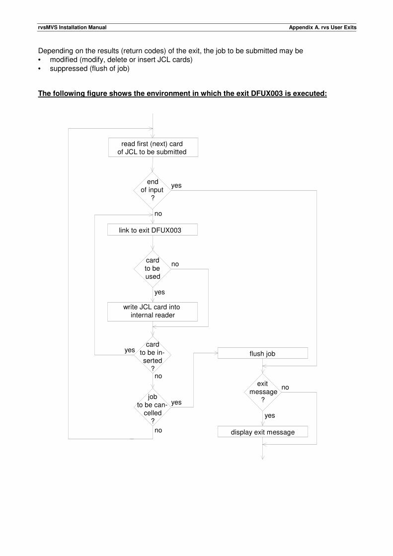
rvsMVS Installation Manual Appendix A. rvs User Exits
Depending on the results (return codes) of the exit, the job to be submitted may be • modified (modify, delete or insert JCL cards) • suppressed (flush of job) The following figure shows the environment in which the exit DFUX003 is executed:
link to exit DFUX003
yes
no
no
read first (next) card of JCL to be submitted
cardto beused
write JCL card intointernal reader
cardto be in-serted
?
jobto be can-
celled?
endof input
?
yes
noexit
message?
flush job
display exit message
yes
yes
no
no
yes
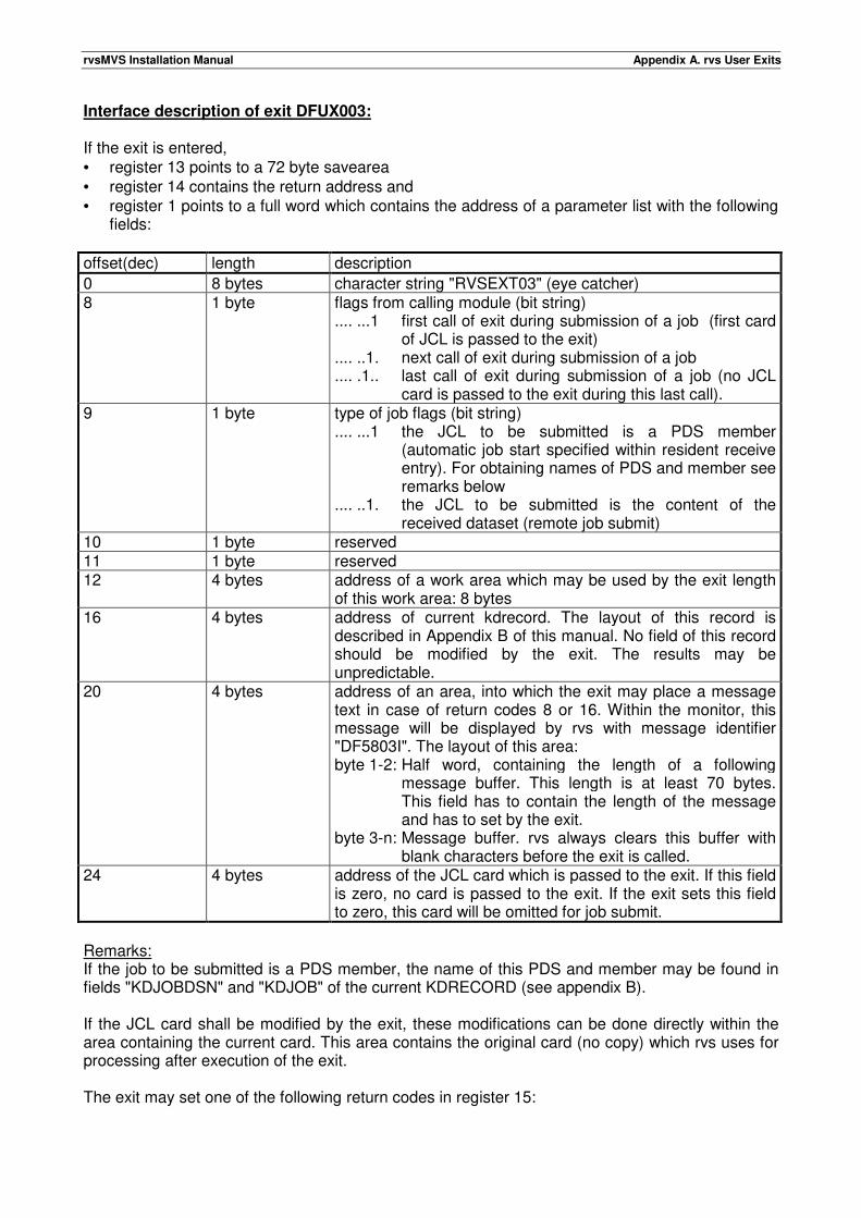
rvsMVS Installation Manual Appendix A. rvs User Exits
Interface description of exit DFUX003: If the exit is entered, • register 13 points to a 72 byte savearea • register 14 contains the return address and • register 1 points to a full word which contains the address of a parameter list with the following
fields:
offset(dec) length description
0 8 bytes character string "RVSEXT03" (eye catcher) 8 1 byte flags from calling module (bit string)
.... ...1 first call of exit during submission of a job (first card of JCL is passed to the exit)
.... ..1. next call of exit during submission of a job
.... .1.. last call of exit during submission of a job (no JCL card is passed to the exit during this last call).
9 1 byte type of job flags (bit string) .... ...1 the JCL to be submitted is a PDS member
(automatic job start specified within resident receive entry). For obtaining names of PDS and member see remarks below
.... ..1. the JCL to be submitted is the content of the received dataset (remote job submit)
10 1 byte reserved 11 1 byte reserved 12 4 bytes address of a work area which may be used by the exit length
of this work area: 8 bytes 16 4 bytes address of current kdrecord. The layout of this record is
described in Appendix B of this manual. No field of this record should be modified by the exit. The results may be unpredictable.
20 4 bytes address of an area, into which the exit may place a message text in case of return codes 8 or 16. Within the monitor, this message will be displayed by rvs with message identifier "DF5803I". The layout of this area: byte 1-2: Half word, containing the length of a following
message buffer. This length is at least 70 bytes. This field has to contain the length of the message and has to set by the exit.
byte 3-n: Message buffer. rvs always clears this buffer with blank characters before the exit is called.
24 4 bytes address of the JCL card which is passed to the exit. If this field is zero, no card is passed to the exit. If the exit sets this field to zero, this card will be omitted for job submit.
Remarks: If the job to be submitted is a PDS member, the name of this PDS and member may be found in fields "KDJOBDSN" and "KDJOB" of the current KDRECORD (see appendix B). If the JCL card shall be modified by the exit, these modifications can be done directly within the area containing the current card. This area contains the original card (no copy) which rvs uses for processing after execution of the exit. The exit may set one of the following return codes in register 15:
rvsMVS Installation Manual Appendix A. rvs User Exits
0 the current JCL card is to be used for job submit. If the address of the card within the parmlist is zero, the card will be omitted.
4 Indication to insert one or more cards. Processing of the current card is done in the same
way as for return code 0, but the next call of the exit is performed without reading the next JCL card.
8 Indication that the exit is no more to be executed during this job submission. Processing
of the current card is done in the same way as for return code 0. All following cards will be read from the input file and stored into the internal reader without execution of the exit. For this return code, a message may be passed from the exit to the calling program.
16 Indication that the job submission is to be cancelled. All prior processed cards are
flushed. For this return code, a message may be passed from the exit to the calling program.
All other return codes will be handled in the same way as return code 16. Rules for coding of exit DFUX003: This exit must be coded reusable or reentrant. The exit must restore the contents of registers 2 - 13 when returning control to the calling rvs program. The exit should not modify • any field of the current record of the rvs Control Dataset ("KDRECORD") • the length field of the message buffer. A.5. Identification User Exit This exit may be used to check, modify and control the identification phase, which is executed on switched BSC lines after establishing of the line connection (dialing). This exit is called by the rvs monitor if the start parameter "IDEXIT=name" has been specified (see chapter 6.1), where "name" denotes the load name of the exit. The exit is executed in following cases: • Immediately before sending of the own identification to the remote station • After reception of the identification from the remote station. If the exit is given control, rvs has
already checked validity of the received station identification. An example for using this exit is to change the SID in the identification phase which fact is given in case of transmission with the 'Daten Austausch Kommunikations System' (DAKS) of Daimler Benz in Germany. For an example look at the end of this appendix. Restrictions: The exit will be executed only within the line control program DF055A00, this means that the line entry within the rvs stations table must specify a program profile, which contains the module name "DF055A00" in columns 4-12. Depending on the results (return codes) of the exit, the identification phase will be cancelled (break of line connection) or continued normally.
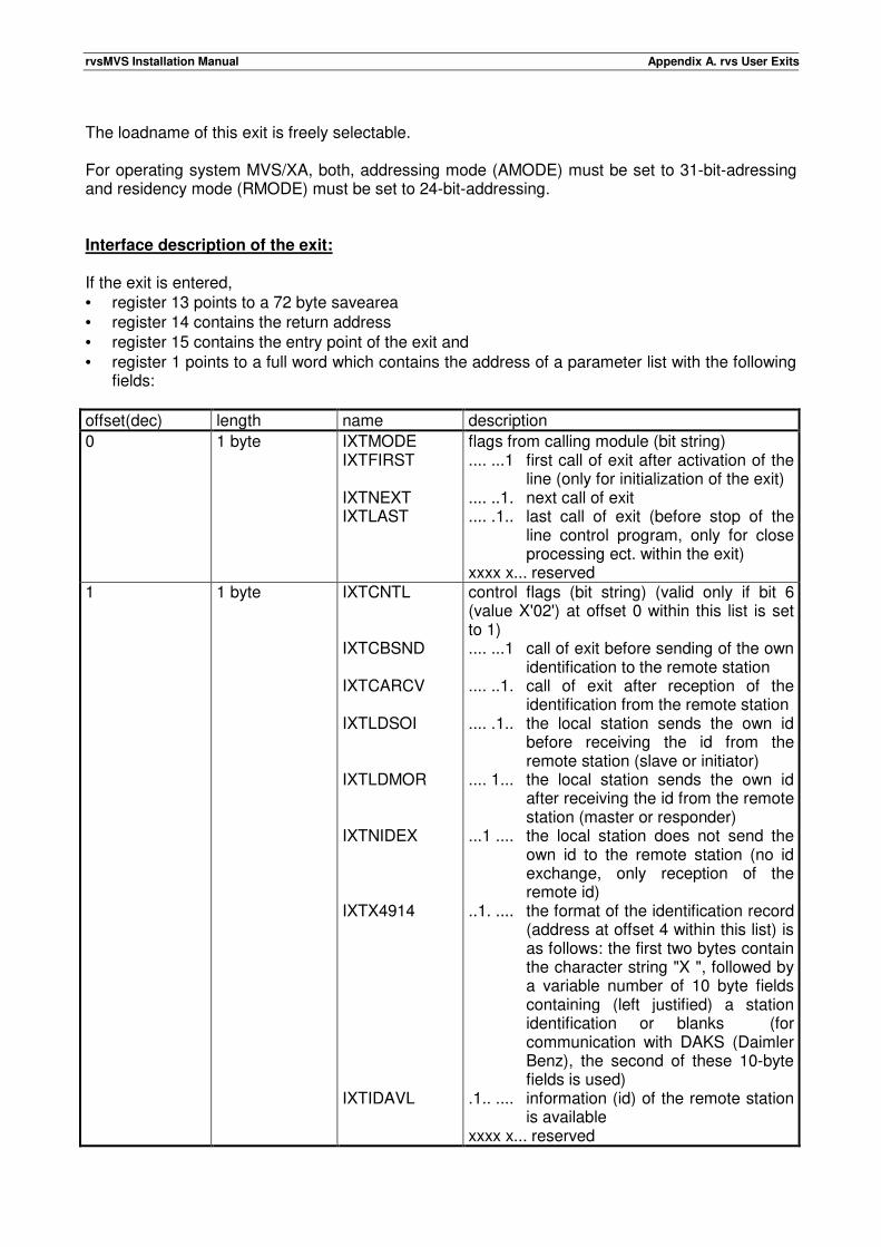
rvsMVS Installation Manual Appendix A. rvs User Exits
The loadname of this exit is freely selectable. For operating system MVS/XA, both, addressing mode (AMODE) must be set to 31-bit-adressing and residency mode (RMODE) must be set to 24-bit-addressing. Interface description of the exit: If the exit is entered, • register 13 points to a 72 byte savearea • register 14 contains the return address • register 15 contains the entry point of the exit and • register 1 points to a full word which contains the address of a parameter list with the following
fields:
offset(dec) length name description
0 1 byte IXTMODE IXTFIRST IXTNEXT IXTLAST
flags from calling module (bit string) .... ...1 first call of exit after activation of the
line (only for initialization of the exit) .... ..1. next call of exit .... .1.. last call of exit (before stop of the
line control program, only for close processing ect. within the exit)
xxxx x... reserved 1 1 byte IXTCNTL
IXTCBSND IXTCARCV IXTLDSOI IXTLDMOR IXTNIDEX IXTX4914 IXTIDAVL
control flags (bit string) (valid only if bit 6 (value X'02') at offset 0 within this list is set to 1) .... ...1 call of exit before sending of the own
identification to the remote station .... ..1. call of exit after reception of the
identification from the remote station .... .1.. the local station sends the own id
before receiving the id from the remote station (slave or initiator)
.... 1... the local station sends the own id after receiving the id from the remote station (master or responder)
...1 .... the local station does not send the own id to the remote station (no id exchange, only reception of the remote id)
..1. .... the format of the identification record (address at offset 4 within this list) is as follows: the first two bytes contain the character string "X ", followed by a variable number of 10 byte fields containing (left justified) a station identification or blanks (for communication with DAKS (Daimler Benz), the second of these 10-byte fields is used)
.1.. .... information (id) of the remote station is available
xxxx x... reserved
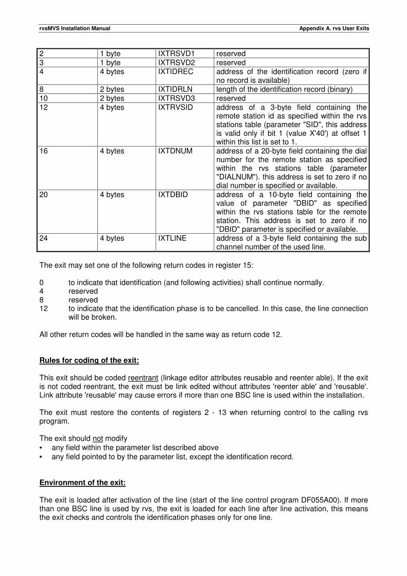
rvsMVS Installation Manual Appendix A. rvs User Exits
2 1 byte IXTRSVD1 reserved 3 1 byte IXTRSVD2 reserved 4 4 bytes IXTIDREC address of the identification record (zero if
no record is available) 8 2 bytes IXTIDRLN length of the identification record (binary) 10 2 bytes IXTRSVD3 reserved 12 4 bytes IXTRVSID address of a 3-byte field containing the
remote station id as specified within the rvs stations table (parameter "SID", this address is valid only if bit 1 (value X'40') at offset 1 within this list is set to 1.
16 4 bytes IXTDNUM address of a 20-byte field containing the dial number for the remote station as specified within the rvs stations table (parameter "DIALNUM"). this address is set to zero if no dial number is specified or available.
20 4 bytes IXTDBID address of a 10-byte field containing the value of parameter "DBID" as specified within the rvs stations table for the remote station. This address is set to zero if no "DBID" parameter is specified or available.
24 4 bytes IXTLINE address of a 3-byte field containing the sub channel number of the used line.
The exit may set one of the following return codes in register 15: 0 to indicate that identification (and following activities) shall continue normally. 4 reserved 8 reserved 12 to indicate that the identification phase is to be cancelled. In this case, the line connection
will be broken. All other return codes will be handled in the same way as return code 12. Rules for coding of the exit: This exit should be coded reentrant (linkage editor attributes reusable and reenter able). If the exit is not coded reentrant, the exit must be link edited without attributes 'reenter able' and 'reusable'. Link attribute 'reusable' may cause errors if more than one BSC line is used within the installation. The exit must restore the contents of registers 2 - 13 when returning control to the calling rvs program. The exit should not modify • any field within the parameter list described above • any field pointed to by the parameter list, except the identification record. Environment of the exit: The exit is loaded after activation of the line (start of the line control program DF055A00). If more than one BSC line is used by rvs, the exit is loaded for each line after line activation, this means the exit checks and controls the identification phases only for one line.
rvsMVS Installation Manual Appendix A. rvs User Exits
After loading the exit, rvs passes control to the exit (first call of exit) in order to allow initialization of the exit (open processing etc.). The next calls of the exit are performed in order to check and control the identification phases which are executed on the line. If the line (line control program) is stopped (rvs command "P lll" or "P ALL"), the exit is given control a last time which may be used for close processing etc. Example: Use of this exit for identification to DAKS's stations (Communication with Daimler Benz) Understanding for use The exit can work successfully only if • rvsMVS is calling with automatic dial (in this case the partner station of Daimler Benz is
known) or • the partner station sends its own identification first. If first rvsMVS sends the identification (slave-reaction) or no automatic dial is used the exit does not work successfully. Working mode The exit changes the identification record (X-record) which will sent by rvs if • the exit is called before sending own identification (exit parameter list, field IXTCNTL, bit
IXTCBSND is on) • Daimler Benz ID of the partner station is known (exit parameter list, field IXTDBID is filled) • the identification record is known (exit parameter list, field IXTIDREC is filled) This
identification record must be 22 bytes long at least (exit parameter list, field IXTIDRLN) and is in conformity with the 'VDA-Empfehlung 4914' (exit parameter list, field IXTX4914)
• the ID table of the exit contains the Daimler Benz ID in the left part (exit table, field IDTAB) If all these four conditions are fulfilled, the right part value of the table replaces the value of the 'STATION'-parameter (rvs-tables dataset, member CNTL: STATION=(sid,dbid) ). For example: The DB-ID addressed by the field IXTDBID has the value '01234567899 '. In this case rvs sends the value '099911590 ' in the X-record. Hints for installation • you can use the exit after modification of the table (field IDTAB)
Note: the right side of the table contains the ID's which rvs is used for identification in the partner station, the left side of the table contains this ID's which the partner station(s) are used for identification to rvs.
• you must declare for rvs the use of the exit in the start parameter (rvs-Tables dataset, member CNTL, parameter 'IDEXIT=loadname')
• the exit is used by the line control program DF055A00 only, check the rvs-Program Profile Table, col. 5-12)
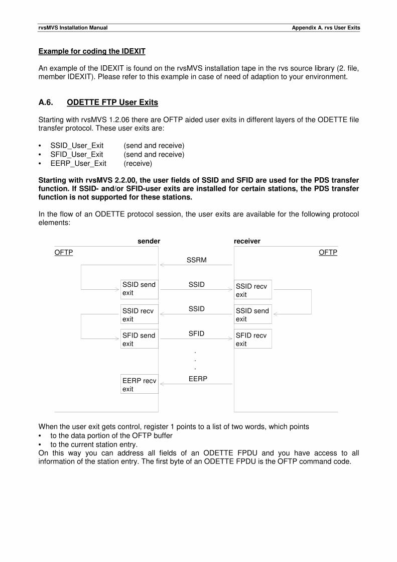
rvsMVS Installation Manual Appendix A. rvs User Exits
Example for coding the IDEXIT An example of the IDEXIT is found on the rvsMVS installation tape in the rvs source library (2. file, member IDEXIT). Please refer to this example in case of need of adaption to your environment. A.6. ODETTE FTP User Exits Starting with rvsMVS 1.2.06 there are OFTP aided user exits in different layers of the ODETTE file transfer protocol. These user exits are: • SSID_User_Exit (send and receive) • SFID_User_Exit (send and receive) • EERP_User_Exit (receive) Starting with rvsMVS 2.2.00, the user fields of SSID and SFID are used for the PDS transfer function. If SSID- and/or SFID-user exits are installed for certain stations, the PDS transfer function is not supported for these stations. In the flow of an ODETTE protocol session, the user exits are available for the following protocol elements:
When the user exit gets control, register 1 points to a list of two words, which points • to the data portion of the OFTP buffer • to the current station entry. On this way you can address all fields of an ODETTE FPDU and you have access to all information of the station entry. The first byte of an ODETTE FPDU is the OFTP command code.
sender receiver
SSRM
SSID
OFTP OFTP
SSID
SSID sendexit
SSID recvexit
SFID sendexit
SFID recvexit
EERP recvexit
SSID sendexit
SSID recvexit
SFID
.
.
.
EERP
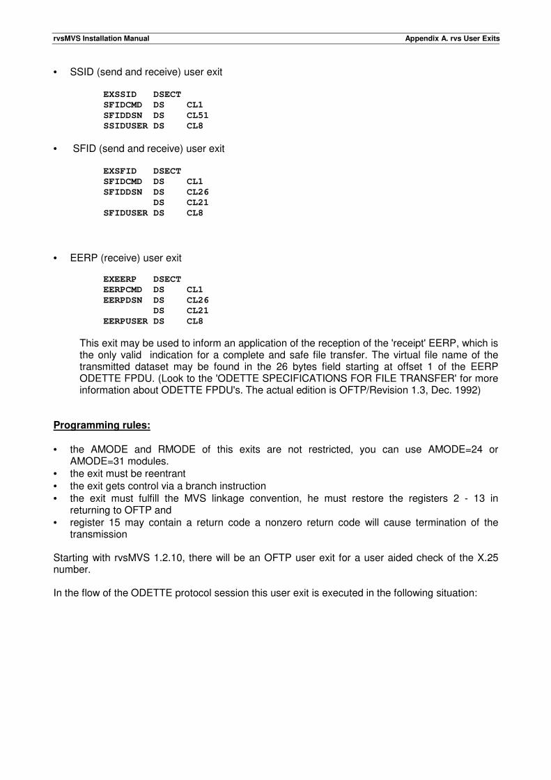
rvsMVS Installation Manual Appendix A. rvs User Exits
• SSID (send and receive) user exit EXSSID DSECT
SFIDCMD DS CL1
SFIDDSN DS CL51
SSIDUSER DS CL8
• SFID (send and receive) user exit EXSFID DSECT
SFIDCMD DS CL1
SFIDDSN DS CL26
DS CL21
SFIDUSER DS CL8
• EERP (receive) user exit
EXEERP DSECT
EERPCMD DS CL1
EERPDSN DS CL26
DS CL21
EERPUSER DS CL8
This exit may be used to inform an application of the reception of the 'receipt' EERP, which is the only valid indication for a complete and safe file transfer. The virtual file name of the transmitted dataset may be found in the 26 bytes field starting at offset 1 of the EERP ODETTE FPDU. (Look to the 'ODETTE SPECIFICATIONS FOR FILE TRANSFER' for more information about ODETTE FPDU's. The actual edition is OFTP/Revision 1.3, Dec. 1992)
Programming rules: • the AMODE and RMODE of this exits are not restricted, you can use AMODE=24 or
AMODE=31 modules. • the exit must be reentrant • the exit gets control via a branch instruction • the exit must fulfill the MVS linkage convention, he must restore the registers 2 - 13 in
returning to OFTP and • register 15 may contain a return code a nonzero return code will cause termination of the
transmission Starting with rvsMVS 1.2.10, there will be an OFTP user exit for a user aided check of the X.25 number. In the flow of the ODETTE protocol session this user exit is executed in the following situation:
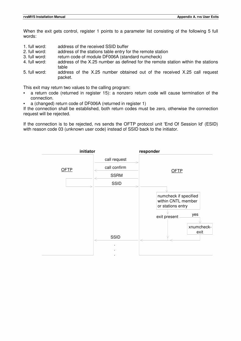
rvsMVS Installation Manual Appendix A. rvs User Exits
When the exit gets control, register 1 points to a parameter list consisting of the following 5 full words: 1. full word: address of the received SSID buffer 2. full word: address of the stations table entry for the remote station 3. full word: return code of module DF006A (standard numcheck) 4. full word: address of the X.25 number as defined for the remote station within the stations
table 5. full word: address of the X.25 number obtained out of the received X.25 call request
packet. This exit may return two values to the calling program: • a return code (returned in register 15): a nonzero return code will cause termination of the
connection. • a (changed) return code of DF006A (returned in register 1) If the connection shall be established, both return codes must be zero, otherwise the connection request will be rejected. If the connection is to be rejected, rvs sends the OFTP protocol unit 'End Of Session Id' (ESID) with reason code 03 (unknown user code) instead of SSID back to the initiator.
initiator responder
call request
call confirm
SSRM
SSID
OFTP OFTP
numcheck if specifiedwithin CNTL member or stations entry
exit present
xnumcheck-exit
yes
SSID
.
.
.
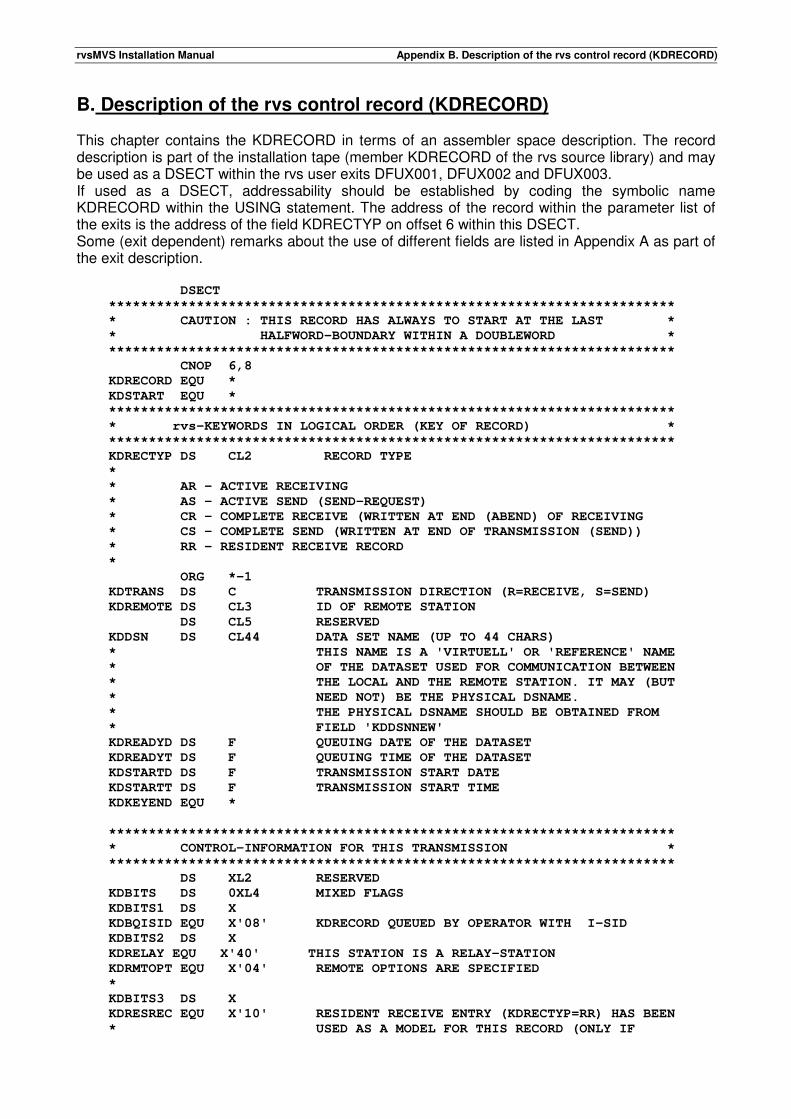
rvsMVS Installation Manual Appendix B. Description of the rvs control record (KDRECORD)
B. Description of the rvs control record (KDRECORD) This chapter contains the KDRECORD in terms of an assembler space description. The record description is part of the installation tape (member KDRECORD of the rvs source library) and may be used as a DSECT within the rvs user exits DFUX001, DFUX002 and DFUX003. If used as a DSECT, addressability should be established by coding the symbolic name KDRECORD within the USING statement. The address of the record within the parameter list of the exits is the address of the field KDRECTYP on offset 6 within this DSECT. Some (exit dependent) remarks about the use of different fields are listed in Appendix A as part of the exit description. DSECT
***********************************************************************
* CAUTION : THIS RECORD HAS ALWAYS TO START AT THE LAST *
* HALFWORD-BOUNDARY WITHIN A DOUBLEWORD *
***********************************************************************
CNOP 6,8
KDRECORD EQU *
KDSTART EQU *
***********************************************************************
* rvs-KEYWORDS IN LOGICAL ORDER (KEY OF RECORD) *
***********************************************************************
KDRECTYP DS CL2 RECORD TYPE
*
* AR - ACTIVE RECEIVING
* AS - ACTIVE SEND (SEND-REQUEST)
* CR - COMPLETE RECEIVE (WRITTEN AT END (ABEND) OF RECEIVING
* CS - COMPLETE SEND (WRITTEN AT END OF TRANSMISSION (SEND))
* RR - RESIDENT RECEIVE RECORD
*
ORG *-1
KDTRANS DS C TRANSMISSION DIRECTION (R=RECEIVE, S=SEND)
KDREMOTE DS CL3 ID OF REMOTE STATION
DS CL5 RESERVED
KDDSN DS CL44 DATA SET NAME (UP TO 44 CHARS)
* THIS NAME IS A 'VIRTUELL' OR 'REFERENCE' NAME
* OF THE DATASET USED FOR COMMUNICATION BETWEEN
* THE LOCAL AND THE REMOTE STATION. IT MAY (BUT
* NEED NOT) BE THE PHYSICAL DSNAME.
* THE PHYSICAL DSNAME SHOULD BE OBTAINED FROM
* FIELD 'KDDSNNEW'
KDREADYD DS F QUEUING DATE OF THE DATASET
KDREADYT DS F QUEUING TIME OF THE DATASET
KDSTARTD DS F TRANSMISSION START DATE
KDSTARTT DS F TRANSMISSION START TIME
KDKEYEND EQU *
***********************************************************************
* CONTROL-INFORMATION FOR THIS TRANSMISSION *
***********************************************************************
DS XL2 RESERVED
KDBITS DS 0XL4 MIXED FLAGS
KDBITS1 DS X
KDBQISID EQU X'08' KDRECORD QUEUED BY OPERATOR WITH I-SID
KDBITS2 DS X
KDRELAY EQU X'40' THIS STATION IS A RELAY-STATION
KDRMTOPT EQU X'04' REMOTE OPTIONS ARE SPECIFIED
*
KDBITS3 DS X
KDRESREC EQU X'10' RESIDENT RECEIVE ENTRY (KDRECTYP=RR) HAS BEEN
* USED AS A MODEL FOR THIS RECORD (ONLY IF
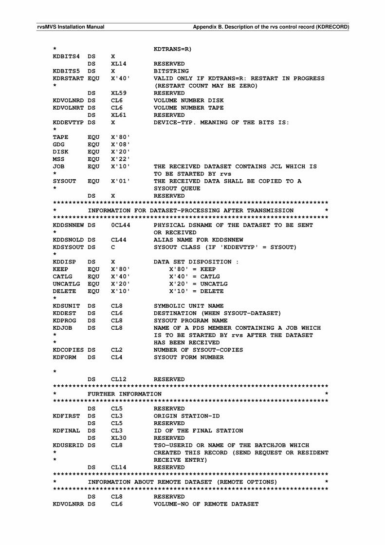
rvsMVS Installation Manual Appendix B. Description of the rvs control record (KDRECORD)
* KDTRANS=R)
KDBITS4 DS X
DS XL14 RESERVED
KDBITS5 DS X BITSTRING
KDRSTART EQU X'40' VALID ONLY IF KDTRANS=R: RESTART IN PROGRESS
* (RESTART COUNT MAY BE ZERO)
DS XL59 RESERVED
KDVOLNRD DS CL6 VOLUME NUMBER DISK
KDVOLNRT DS CL6 VOLUME NUMBER TAPE
DS XL61 RESERVED
KDDEVTYP DS X DEVICE-TYP. MEANING OF THE BITS IS:
*
TAPE EQU X'80'
GDG EQU X'08'
DISK EQU X'20'
MSS EQU X'22'
JOB EQU X'10' THE RECEIVED DATASET CONTAINS JCL WHICH IS
* TO BE STARTED BY rvs
SYSOUT EQU X'01' THE RECEIVED DATA SHALL BE COPIED TO A
* SYSOUT QUEUE
DS X RESERVED
***********************************************************************
* INFORMATION FOR DATASET-PROCESSING AFTER TRANSMISSION *
***********************************************************************
KDDSNNEW DS 0CL44 PHYSICAL DSNAME OF THE DATASET TO BE SENT
* OR RECEIVED
KDDSNOLD DS CL44 ALIAS NAME FOR KDDSNNEW
KDSYSOUT DS C SYSOUT CLASS (IF 'KDDEVTYP' = SYSOUT)
*
KDDISP DS X DATA SET DISPOSITION :
KEEP EQU X'80' X'80' = KEEP
CATLG EQU X'40' X'40' = CATLG
UNCATLG EQU X'20' X'20' = UNCATLG
DELETE EQU X'10' X'10' = DELETE
*
KDSUNIT DS CL8 SYMBOLIC UNIT NAME
KDDEST DS CL6 DESTINATION (WHEN SYSOUT-DATASET)
KDPROG DS CL8 SYSOUT PROGRAM NAME
KDJOB DS CL8 NAME OF A PDS MEMBER CONTAINING A JOB WHICH
* IS TO BE STARTED BY rvs AFTER THE DATASET
* HAS BEEN RECEIVED
KDCOPIES DS CL2 NUMBER OF SYSOUT-COPIES
KDFORM DS CL4 SYSOUT FORM NUMBER
*
DS CL12 RESERVED
***********************************************************************
* FURTHER INFORMATION *
***********************************************************************
DS CL5 RESERVED
KDFIRST DS CL3 ORIGIN STATION-ID
DS CL5 RESERVED
KDFINAL DS CL3 ID OF THE FINAL STATION
DS XL30 RESERVED
KDUSERID DS CL8 TSO-USERID OR NAME OF THE BATCHJOB WHICH
* CREATED THIS RECORD (SEND REQUEST OR RESIDENT
* RECEIVE ENTRY)
DS CL14 RESERVED
***********************************************************************
* INFORMATION ABOUT REMOTE DATASET (REMOTE OPTIONS) *
***********************************************************************
DS CL8 RESERVED
KDVOLNRR DS CL6 VOLUME-NO OF REMOTE DATASET
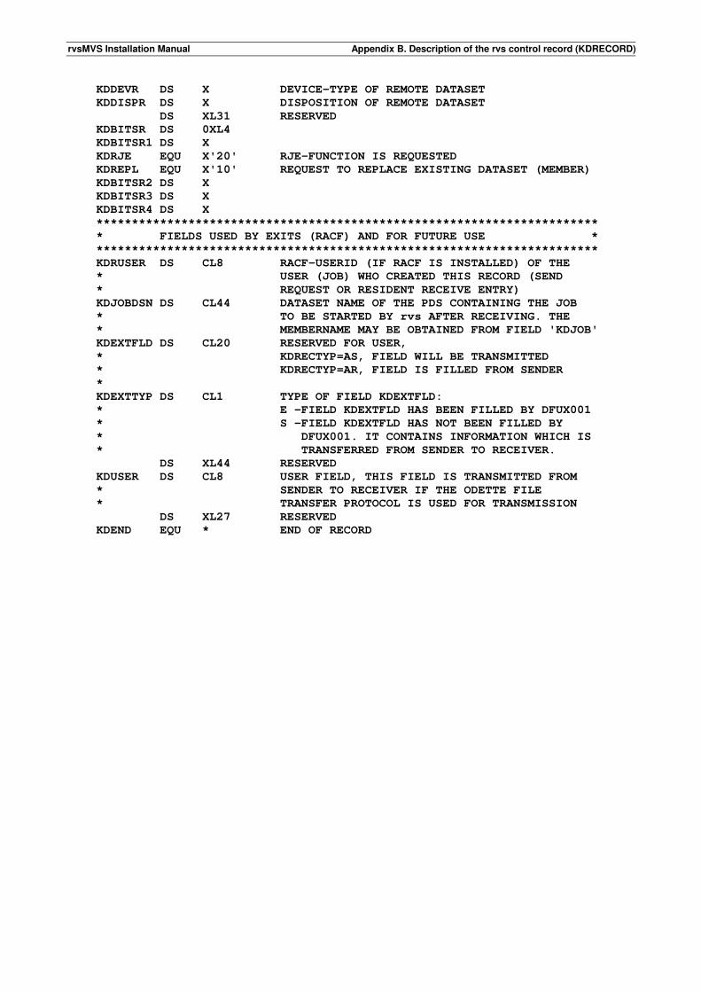
rvsMVS Installation Manual Appendix B. Description of the rvs control record (KDRECORD)
KDDEVR DS X DEVICE-TYPE OF REMOTE DATASET
KDDISPR DS X DISPOSITION OF REMOTE DATASET
DS XL31 RESERVED
KDBITSR DS 0XL4
KDBITSR1 DS X
KDRJE EQU X'20' RJE-FUNCTION IS REQUESTED
KDREPL EQU X'10' REQUEST TO REPLACE EXISTING DATASET (MEMBER)
KDBITSR2 DS X
KDBITSR3 DS X
KDBITSR4 DS X
***********************************************************************
* FIELDS USED BY EXITS (RACF) AND FOR FUTURE USE *
***********************************************************************
KDRUSER DS CL8 RACF-USERID (IF RACF IS INSTALLED) OF THE
* USER (JOB) WHO CREATED THIS RECORD (SEND
* REQUEST OR RESIDENT RECEIVE ENTRY)
KDJOBDSN DS CL44 DATASET NAME OF THE PDS CONTAINING THE JOB
* TO BE STARTED BY rvs AFTER RECEIVING. THE
* MEMBERNAME MAY BE OBTAINED FROM FIELD 'KDJOB'
KDEXTFLD DS CL20 RESERVED FOR USER,
* KDRECTYP=AS, FIELD WILL BE TRANSMITTED
* KDRECTYP=AR, FIELD IS FILLED FROM SENDER
*
KDEXTTYP DS CL1 TYPE OF FIELD KDEXTFLD:
* E -FIELD KDEXTFLD HAS BEEN FILLED BY DFUX001
* S -FIELD KDEXTFLD HAS NOT BEEN FILLED BY
* DFUX001. IT CONTAINS INFORMATION WHICH IS
* TRANSFERRED FROM SENDER TO RECEIVER.
DS XL44 RESERVED
KDUSER DS CL8 USER FIELD, THIS FIELD IS TRANSMITTED FROM
* SENDER TO RECEIVER IF THE ODETTE FILE
* TRANSFER PROTOCOL IS USED FOR TRANSMISSION
DS XL27 RESERVED
KDEND EQU * END OF RECORD
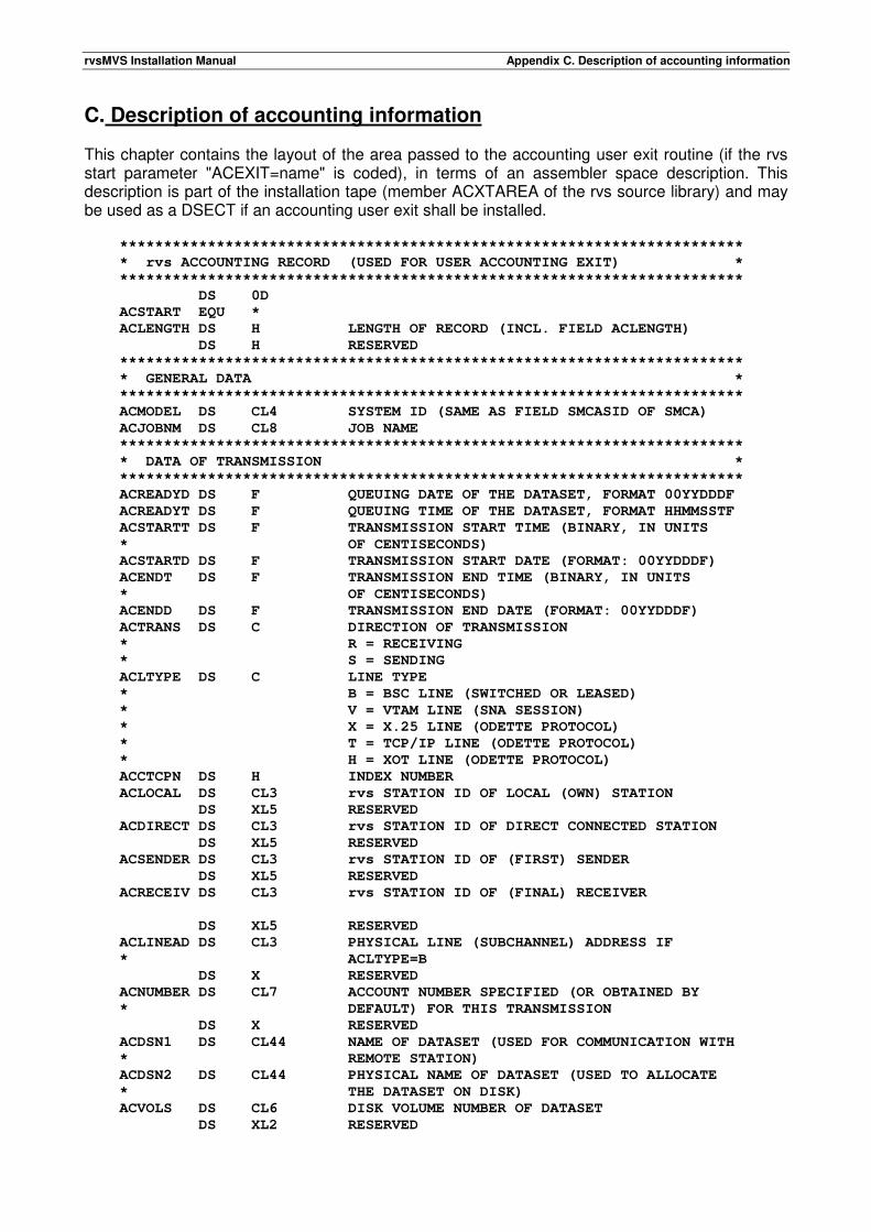
rvsMVS Installation Manual Appendix C. Description of accounting information
C. Description of accounting information This chapter contains the layout of the area passed to the accounting user exit routine (if the rvs start parameter "ACEXIT=name" is coded), in terms of an assembler space description. This description is part of the installation tape (member ACXTAREA of the rvs source library) and may be used as a DSECT if an accounting user exit shall be installed. ***********************************************************************
* rvs ACCOUNTING RECORD (USED FOR USER ACCOUNTING EXIT) *
***********************************************************************
DS 0D
ACSTART EQU *
ACLENGTH DS H LENGTH OF RECORD (INCL. FIELD ACLENGTH)
DS H RESERVED
***********************************************************************
* GENERAL DATA *
***********************************************************************
ACMODEL DS CL4 SYSTEM ID (SAME AS FIELD SMCASID OF SMCA)
ACJOBNM DS CL8 JOB NAME
***********************************************************************
* DATA OF TRANSMISSION *
***********************************************************************
ACREADYD DS F QUEUING DATE OF THE DATASET, FORMAT 00YYDDDF
ACREADYT DS F QUEUING TIME OF THE DATASET, FORMAT HHMMSSTF
ACSTARTT DS F TRANSMISSION START TIME (BINARY, IN UNITS
* OF CENTISECONDS)
ACSTARTD DS F TRANSMISSION START DATE (FORMAT: 00YYDDDF)
ACENDT DS F TRANSMISSION END TIME (BINARY, IN UNITS
* OF CENTISECONDS)
ACENDD DS F TRANSMISSION END DATE (FORMAT: 00YYDDDF)
ACTRANS DS C DIRECTION OF TRANSMISSION
* R = RECEIVING
* S = SENDING
ACLTYPE DS C LINE TYPE
* B = BSC LINE (SWITCHED OR LEASED)
* V = VTAM LINE (SNA SESSION)
* X = X.25 LINE (ODETTE PROTOCOL)
* T = TCP/IP LINE (ODETTE PROTOCOL)
* H = XOT LINE (ODETTE PROTOCOL)
ACCTCPN DS H INDEX NUMBER
ACLOCAL DS CL3 rvs STATION ID OF LOCAL (OWN) STATION
DS XL5 RESERVED
ACDIRECT DS CL3 rvs STATION ID OF DIRECT CONNECTED STATION
DS XL5 RESERVED
ACSENDER DS CL3 rvs STATION ID OF (FIRST) SENDER
DS XL5 RESERVED
ACRECEIV DS CL3 rvs STATION ID OF (FINAL) RECEIVER
DS XL5 RESERVED
ACLINEAD DS CL3 PHYSICAL LINE (SUBCHANNEL) ADDRESS IF
* ACLTYPE=B
DS X RESERVED
ACNUMBER DS CL7 ACCOUNT NUMBER SPECIFIED (OR OBTAINED BY
* DEFAULT) FOR THIS TRANSMISSION
DS X RESERVED
ACDSN1 DS CL44 NAME OF DATASET (USED FOR COMMUNICATION WITH
* REMOTE STATION)
ACDSN2 DS CL44 PHYSICAL NAME OF DATASET (USED TO ALLOCATE
* THE DATASET ON DISK)
ACVOLS DS CL6 DISK VOLUME NUMBER OF DATASET
DS XL2 RESERVED
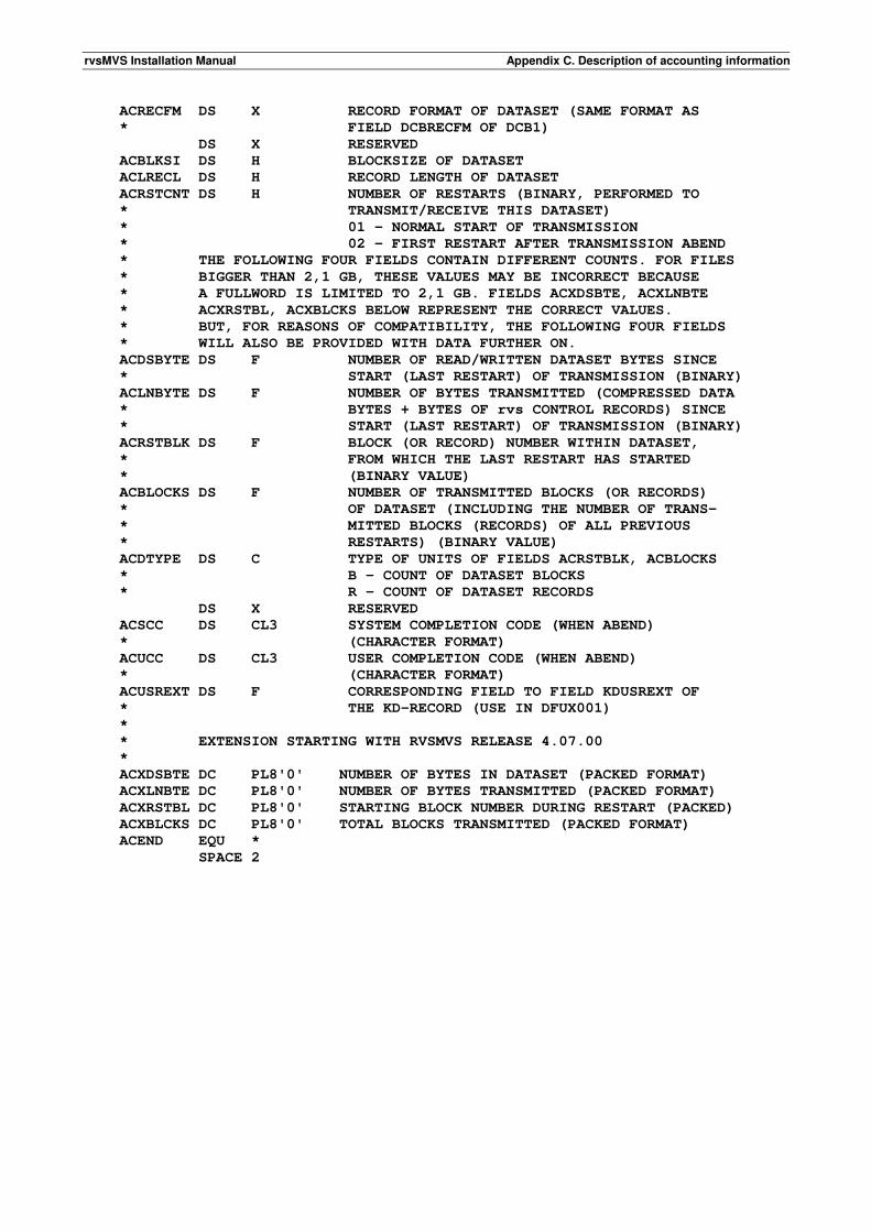
rvsMVS Installation Manual Appendix C. Description of accounting information
ACRECFM DS X RECORD FORMAT OF DATASET (SAME FORMAT AS
* FIELD DCBRECFM OF DCB1)
DS X RESERVED
ACBLKSI DS H BLOCKSIZE OF DATASET
ACLRECL DS H RECORD LENGTH OF DATASET
ACRSTCNT DS H NUMBER OF RESTARTS (BINARY, PERFORMED TO
* TRANSMIT/RECEIVE THIS DATASET)
* 01 - NORMAL START OF TRANSMISSION
* 02 - FIRST RESTART AFTER TRANSMISSION ABEND
* THE FOLLOWING FOUR FIELDS CONTAIN DIFFERENT COUNTS. FOR FILES
* BIGGER THAN 2,1 GB, THESE VALUES MAY BE INCORRECT BECAUSE
* A FULLWORD IS LIMITED TO 2,1 GB. FIELDS ACXDSBTE, ACXLNBTE
* ACXRSTBL, ACXBLCKS BELOW REPRESENT THE CORRECT VALUES.
* BUT, FOR REASONS OF COMPATIBILITY, THE FOLLOWING FOUR FIELDS
* WILL ALSO BE PROVIDED WITH DATA FURTHER ON.
ACDSBYTE DS F NUMBER OF READ/WRITTEN DATASET BYTES SINCE
* START (LAST RESTART) OF TRANSMISSION (BINARY)
ACLNBYTE DS F NUMBER OF BYTES TRANSMITTED (COMPRESSED DATA
* BYTES + BYTES OF rvs CONTROL RECORDS) SINCE
* START (LAST RESTART) OF TRANSMISSION (BINARY)
ACRSTBLK DS F BLOCK (OR RECORD) NUMBER WITHIN DATASET,
* FROM WHICH THE LAST RESTART HAS STARTED
* (BINARY VALUE)
ACBLOCKS DS F NUMBER OF TRANSMITTED BLOCKS (OR RECORDS)
* OF DATASET (INCLUDING THE NUMBER OF TRANS-
* MITTED BLOCKS (RECORDS) OF ALL PREVIOUS
* RESTARTS) (BINARY VALUE)
ACDTYPE DS C TYPE OF UNITS OF FIELDS ACRSTBLK, ACBLOCKS
* B - COUNT OF DATASET BLOCKS
* R - COUNT OF DATASET RECORDS
DS X RESERVED
ACSCC DS CL3 SYSTEM COMPLETION CODE (WHEN ABEND)
* (CHARACTER FORMAT)
ACUCC DS CL3 USER COMPLETION CODE (WHEN ABEND)
* (CHARACTER FORMAT)
ACUSREXT DS F CORRESPONDING FIELD TO FIELD KDUSREXT OF
* THE KD-RECORD (USE IN DFUX001)
*
* EXTENSION STARTING WITH RVSMVS RELEASE 4.07.00
*
ACXDSBTE DC PL8'0' NUMBER OF BYTES IN DATASET (PACKED FORMAT)
ACXLNBTE DC PL8'0' NUMBER OF BYTES TRANSMITTED (PACKED FORMAT)
ACXRSTBL DC PL8'0' STARTING BLOCK NUMBER DURING RESTART (PACKED)
ACXBLCKS DC PL8'0' TOTAL BLOCKS TRANSMITTED (PACKED FORMAT)
ACEND EQU *
SPACE 2
rvsMVS Installation Manual Appendix D. rvs statistics
D. rvs statistics D.1. General Information Station Activity The rvs Station Activity program provides a station related summary of all important transmission data (like number of transmissions, number of transmitted bytes, speed etc.). Statistics are available for • a single station, • a group of stations (groups must be specified by the user, see D.4a) all stations Possible time intervals of calculation are • one day, or • one month. Line Activity The rvs Line Activity Program generates a chart which shows the usage of a switched line • per day of the chosen month, or • per hour of the chosen day. D.2. Prerequisites Dataset 'RVS.TPSTAT' Basic data will be accumulated in a permanent dataset which is used as data base of both of the rvs statistics programs. It is called 'RVS.TPSTAT' hereafter and should have following attributes: ORGANIZATION: physical sequential RECORD FORMAT: fixed blocked RECORD LENGTH: 39 bytes BLOCK SIZE: 19500 bytes (may be changed) SPACE: 1 cylinder (approx.) Important: Each transmission is represented within 'RVS.TPSTAT' by a 39-byte record. Assumed that the average number of transmissions per day is 30, the chosen space of 1 cylinder of a 3380 disk (approx. 40000 bytes/track), is big enough to accumulate statistics data of more than 1 year (500 days). If more transmissions are planned or already executed the space specification must be increased to avoid overflow. D.3. Job to gain the basic data for the statistics Basic data will be obtained from an rvs log file called 'RVS.LOG.SAVE' (assigned DD-name 'LOGSAVE' within kdsave/logsave procedure, see member PDF0014A of 'RVS.TABLES'). Important: It is necessary to run the accumulation job immediately after the kdsave/logsave procedure to be sure that 'RVS.LOG.SAVE' contains only data since the last save procedure.
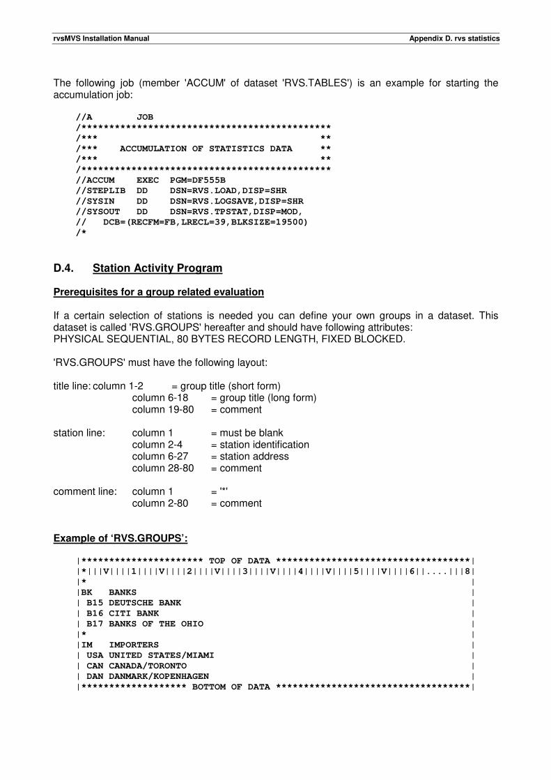
rvsMVS Installation Manual Appendix D. rvs statistics
The following job (member 'ACCUM' of dataset 'RVS.TABLES') is an example for starting the accumulation job: //A JOB
/*********************************************
/*** **
/*** ACCUMULATION OF STATISTICS DATA **
/*** **
/*********************************************
//ACCUM EXEC PGM=DF555B
//STEPLIB DD DSN=RVS.LOAD,DISP=SHR
//SYSIN DD DSN=RVS.LOGSAVE,DISP=SHR
//SYSOUT DD DSN=RVS.TPSTAT,DISP=MOD,
// DCB=(RECFM=FB,LRECL=39,BLKSIZE=19500)
/*
D.4. Station Activity Program Prerequisites for a group related evaluation If a certain selection of stations is needed you can define your own groups in a dataset. This dataset is called 'RVS.GROUPS' hereafter and should have following attributes: PHYSICAL SEQUENTIAL, 80 BYTES RECORD LENGTH, FIXED BLOCKED. 'RVS.GROUPS' must have the following layout: title line: column 1-2 = group title (short form) column 6-18 = group title (long form)
column 19-80 = comment station line: column 1 = must be blank column 2-4 = station identification
column 6-27 = station address column 28-80 = comment
comment line: column 1 = '*' column 2-80 = comment Example of ‘RVS.GROUPS’: |********************** TOP OF DATA ***********************************|
|*|||V||||1||||V||||2||||V||||3||||V||||4||||V||||5||||V||||6||....|||8|
|* |
|BK BANKS |
| B15 DEUTSCHE BANK |
| B16 CITI BANK |
| B17 BANKS OF THE OHIO |
|* |
|IM IMPORTERS |
| USA UNITED STATES/MIAMI |
| CAN CANADA/TORONTO |
| DAN DANMARK/KOPENHAGEN |
|******************* BOTTOM OF DATA ***********************************|
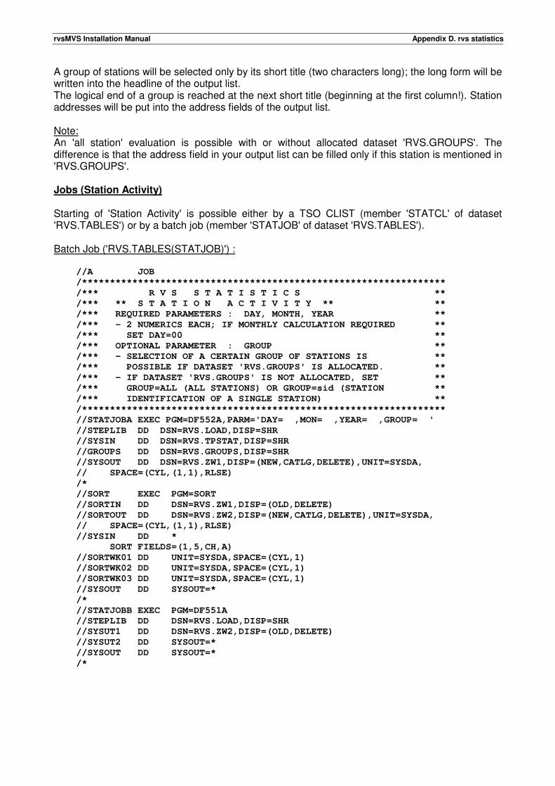
rvsMVS Installation Manual Appendix D. rvs statistics
A group of stations will be selected only by its short title (two characters long); the long form will be written into the headline of the output list. The logical end of a group is reached at the next short title (beginning at the first column!). Station addresses will be put into the address fields of the output list. Note: An 'all station' evaluation is possible with or without allocated dataset 'RVS.GROUPS'. The difference is that the address field in your output list can be filled only if this station is mentioned in 'RVS.GROUPS'. Jobs (Station Activity) Starting of 'Station Activity' is possible either by a TSO CLIST (member 'STATCL' of dataset 'RVS.TABLES') or by a batch job (member 'STATJOB' of dataset 'RVS.TABLES'). Batch Job ('RVS.TABLES(STATJOB)') : //A JOB
/*****************************************************************
/*** R V S S T A T I S T I C S **
/*** ** S T A T I O N A C T I V I T Y ** **
/*** REQUIRED PARAMETERS : DAY, MONTH, YEAR **
/*** - 2 NUMERICS EACH; IF MONTHLY CALCULATION REQUIRED **
/*** SET DAY=00 **
/*** OPTIONAL PARAMETER : GROUP **
/*** - SELECTION OF A CERTAIN GROUP OF STATIONS IS **
/*** POSSIBLE IF DATASET 'RVS.GROUPS' IS ALLOCATED. **
/*** - IF DATASET 'RVS.GROUPS' IS NOT ALLOCATED, SET **
/*** GROUP=ALL (ALL STATIONS) OR GROUP=sid (STATION **
/*** IDENTIFICATION OF A SINGLE STATION) **
/*****************************************************************
//STATJOBA EXEC PGM=DF552A,PARM='DAY= ,MON= ,YEAR= ,GROUP= '
//STEPLIB DD DSN=RVS.LOAD,DISP=SHR
//SYSIN DD DSN=RVS.TPSTAT,DISP=SHR
//GROUPS DD DSN=RVS.GROUPS,DISP=SHR
//SYSOUT DD DSN=RVS.ZW1,DISP=(NEW,CATLG,DELETE),UNIT=SYSDA,
// SPACE=(CYL,(1,1),RLSE)
/*
//SORT EXEC PGM=SORT
//SORTIN DD DSN=RVS.ZW1,DISP=(OLD,DELETE)
//SORTOUT DD DSN=RVS.ZW2,DISP=(NEW,CATLG,DELETE),UNIT=SYSDA,
// SPACE=(CYL,(1,1),RLSE)
//SYSIN DD *
SORT FIELDS=(1,5,CH,A)
//SORTWK01 DD UNIT=SYSDA,SPACE=(CYL,1)
//SORTWK02 DD UNIT=SYSDA,SPACE=(CYL,1)
//SORTWK03 DD UNIT=SYSDA,SPACE=(CYL,1)
//SYSOUT DD SYSOUT=*
/*
//STATJOBB EXEC PGM=DF551A
//STEPLIB DD DSN=RVS.LOAD,DISP=SHR
//SYSUT1 DD DSN=RVS.ZW2,DISP=(OLD,DELETE)
//SYSUT2 DD SYSOUT=*
//SYSOUT DD SYSOUT=*
/*
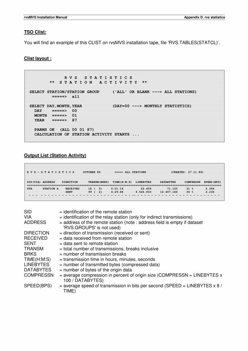
rvsMVS Installation Manual Appendix D. rvs statistics
TSO Clist: You will find an example of this CLIST on rvsMVS installation tape, file 'RVS.TABLES(STATCL)'. Clist layout :
R V S S T A T I S T I C S
** S T A T I O N A C T I V I T Y **
SELECT STATION/STATION GROUP ('ALL' OR BLANK ---> ALL STATIONS)
=====> all
SELECT DAY,MONTH,YEAR (DAY=00 ---> MONTHLY STATISTICS)
DAY =====> 00
MONTH =====> 01
YEAR =====> 87
PARMS OK (ALL 00 01 87)
CALCULATION OF STATION ACTIVITY STARTS ...
Output List (Station Activity)
R V S - S T A T I S T I C S OCTOBER 86 ====> ALL STATIONS (CREATED: 27.11.86)
SID(VIA) ADDRESS DIRECTION TRANSM(BRKS) TIME(H:M:S) LINEBYTES DATABYTES COMPRESSN SPEED(BPS)
===============================================================================================================
STA STATION A RECEIVED 18 ( 0) 0:01:16 22.609 71.120 31 % 2.364
SENT 99 ( 2) 4:29:48 4.524.933 12.407.166 36 % 2.236
- - - - - - - - - - - - - - - - - - - - - - - - - - - - - -- - - - - - - - - - - - - - - - - - - - - - - - -
SID = identification of the remote station VIA = identification of the relay station (only for indirect transmissions) ADDRESS = address of the remote station (note : address field is empty if dataset
'RVS.GROUPS' is not used) DIRECTION = direction of transmission (received or sent) RECEIVED = data received from remote station SENT = data sent to remote station TRANSM = total number of transmissions, breaks inclusive BRKS = number of transmission breaks TIME(H:M:S) = transmission time in hours, minutes, seconds LINEBYTES = number of transmitted bytes (compressed data) DATABYTES = number of bytes of the origin data COMPRESSN = average compression in percent of origin size (COMPRESSN = LINEBYTES x
100 / DATABYTES) SPEED(BPS) = average speed of transmission in bits per second (SPEED = LINEBYTES x 8 /
TIME)
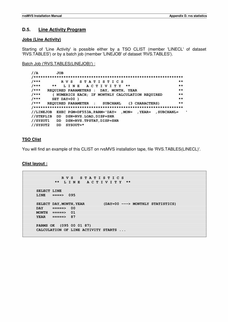
rvsMVS Installation Manual Appendix D. rvs statistics
D.5. Line Activity Program Jobs (Line Activity) Starting of 'Line Activity' is possible either by a TSO CLIST (member 'LINECL' of dataset 'RVS.TABLES') or by a batch job (member 'LINEJOB' of dataset 'RVS.TABLES'). Batch Job ('RVS.TABLES(LINEJOB)') : //A JOB
/*****************************************************************
/*** R V S S T A T I S T I C S **
/*** ** L I N E A C T I V I T Y ** **
/*** REQUIRED PARAMETERS : DAY, MONTH, YEAR **
/*** ( NUMERICS EACH; IF MONTHLY CALCULATION REQUIRED **
/*** SET DAY=00 ) **
/*** REQUIRED PARAMETER : SUBCHANL (3 CHARACTERS) **
/*****************************************************************
//LINEJOB EXEC PGM=DF553A,PARM='DAY= ,MON= ,YEAR= ,SUBCHANL= '
//STEPLIB DD DSN=RVS.LOAD,DISP=SHR
//SYSUT1 DD DSN=RVS.TPSTAT,DISP=SHR
//SYSUT2 DD SYSOUT=*
TSO Clist You will find an example of this CLIST on rvsMVS installation tape, file 'RVS.TABLES(LINECL)'. Clist layout :
R V S S T A T I S T I C S
** L I N E A C T I V I T Y **
SELECT LINE
LINE ====> 095
SELECT DAY,MONTH,YEAR (DAY=00 ---> MONTHLY STATISTICS)
DAY =====> 00
MONTH =====> 01
YEAR =====> 87
PARMS OK (095 00 01 87)
CALCULATION OF LINE ACTIVITY STARTS ...
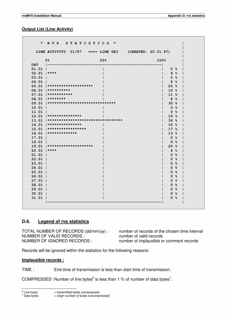
rvsMVS Installation Manual Appendix D. rvs statistics
Output List (Line Activity)
* R V S S T A T I S T I C S * |
|
LINE ACTIVITY 01/87 ===> LINE 0E3 (CREATED: 20.01.87) |
|
0% 25% 100% |
DAY |--------------------------------------------------| |
01.01 | | | 0 % |
02.01 |**** | | 4 % |
03.01 | | | 0 % |
04.01 | | | 0 % |
05.01 |******************** | | 20 % |
06.01 |********** | | 10 % |
07.01 |*********** | | 11 % |
08.01 |******** | | 8 % |
09.01 |****************************** | 30 % |
10.01 | | | 0 % |
11.01 | | | 0 % |
12.01 |*************** | | 15 % |
13.01 |********************************* | 34 % |
14.01 |*************** | | 15 % |
15.01 |***************** | | 17 % |
16.01 |************* | | 13 % |
17.01 | | | 0 % |
18.01 | | | 0 % |
19.01 |******************** | | 20 % |
20.01 |**** | | 4 % |
21.01 | | | 0 % |
22.01 | | | 0 % |
23.01 | | | 0 % |
24.01 | | | 0 % |
25.01 | | | 0 % |
26.01 | | | 0 % |
27.01 | | | 0 % |
28.01 | | | 0 % |
29.01 | | | 0 % |
30.01 | | | 0 % |
31.01 | | | 0 % |
|--------------------------------------------------| |
D.6. Legend of rvs statistics TOTAL NUMBER OF RECORDS (dd/mm/yy) : number of records of the chosen time interval NUMBER OF VALID RECORDS : number of valid records NUMBER OF IGNORED RECORDS : number of implausible or comment records Records will be ignored within the statistics for the following reasons: Implausible records : TIME : End time of transmission is less than start time of transmission. COMPRESSED : Number of line bytes6 is less than 1 % of number of data bytes7.
6 Line bytes = transmitted bytes (compressed) 7 Data bytes = origin number of bytes (uncompressed)
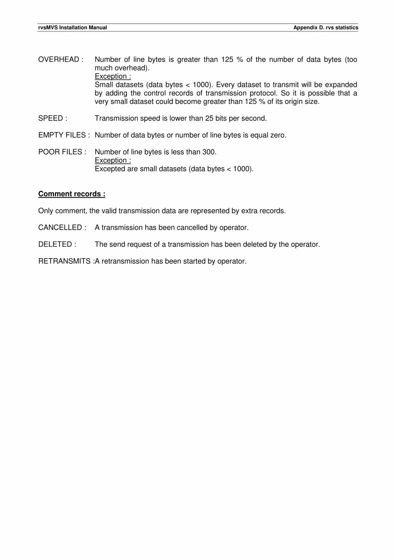
rvsMVS Installation Manual Appendix D. rvs statistics
OVERHEAD : Number of line bytes is greater than 125 % of the number of data bytes (too
much overhead). Exception : Small datasets (data bytes < 1000). Every dataset to transmit will be expanded by adding the control records of transmission protocol. So it is possible that a very small dataset could become greater than 125 % of its origin size.
SPEED : Transmission speed is lower than 25 bits per second. EMPTY FILES : Number of data bytes or number of line bytes is equal zero. POOR FILES : Number of line bytes is less than 300.
Exception : Excepted are small datasets (data bytes < 1000).
Comment records : Only comment, the valid transmission data are represented by extra records. CANCELLED : A transmission has been cancelled by operator. DELETED : The send request of a transmission has been deleted by the operator. RETRANSMITS : A retransmission has been started by operator.

rvsMVS Installation Manual Appendix D. rvs statistics
This page will be intentionally empty.
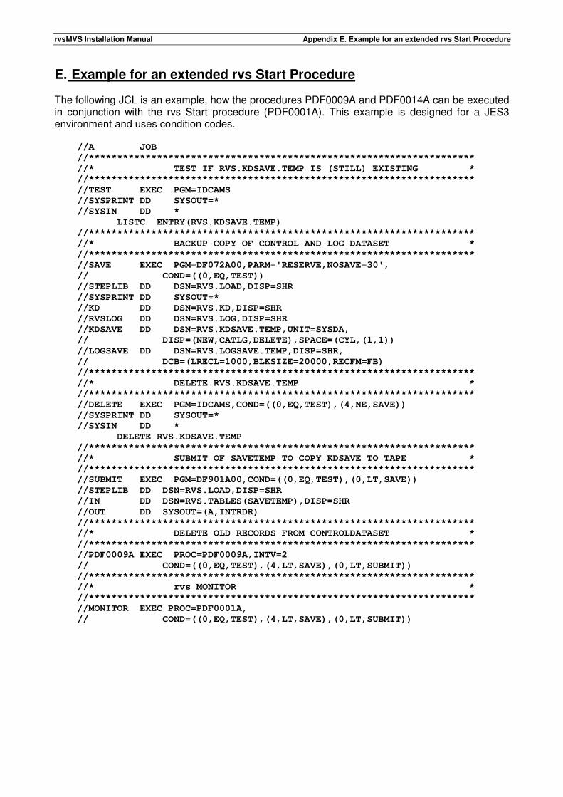
rvsMVS Installation Manual Appendix E. Example for an extended rvs Start Procedure
E. Example for an extended rvs Start Procedure The following JCL is an example, how the procedures PDF0009A and PDF0014A can be executed in conjunction with the rvs Start procedure (PDF0001A). This example is designed for a JES3 environment and uses condition codes. //A JOB
//********************************************************************
//* TEST IF RVS.KDSAVE.TEMP IS (STILL) EXISTING *
//********************************************************************
//TEST EXEC PGM=IDCAMS
//SYSPRINT DD SYSOUT=*
//SYSIN DD *
LISTC ENTRY(RVS.KDSAVE.TEMP)
//********************************************************************
//* BACKUP COPY OF CONTROL AND LOG DATASET *
//********************************************************************
//SAVE EXEC PGM=DF072A00,PARM='RESERVE,NOSAVE=30',
// COND=((0,EQ,TEST))
//STEPLIB DD DSN=RVS.LOAD,DISP=SHR
//SYSPRINT DD SYSOUT=*
//KD DD DSN=RVS.KD,DISP=SHR
//RVSLOG DD DSN=RVS.LOG,DISP=SHR
//KDSAVE DD DSN=RVS.KDSAVE.TEMP,UNIT=SYSDA,
// DISP=(NEW,CATLG,DELETE),SPACE=(CYL,(1,1))
//LOGSAVE DD DSN=RVS.LOGSAVE.TEMP,DISP=SHR,
// DCB=(LRECL=1000,BLKSIZE=20000,RECFM=FB)
//********************************************************************
//* DELETE RVS.KDSAVE.TEMP *
//********************************************************************
//DELETE EXEC PGM=IDCAMS,COND=((0,EQ,TEST),(4,NE,SAVE))
//SYSPRINT DD SYSOUT=*
//SYSIN DD *
DELETE RVS.KDSAVE.TEMP
//********************************************************************
//* SUBMIT OF SAVETEMP TO COPY KDSAVE TO TAPE *
//********************************************************************
//SUBMIT EXEC PGM=DF901A00,COND=((0,EQ,TEST),(0,LT,SAVE))
//STEPLIB DD DSN=RVS.LOAD,DISP=SHR
//IN DD DSN=RVS.TABLES(SAVETEMP),DISP=SHR
//OUT DD SYSOUT=(A,INTRDR)
//********************************************************************
//* DELETE OLD RECORDS FROM CONTROLDATASET *
//********************************************************************
//PDF0009A EXEC PROC=PDF0009A,INTV=2
// COND=((0,EQ,TEST),(4,LT,SAVE),(0,LT,SUBMIT))
//********************************************************************
//* rvs MONITOR *
//********************************************************************
//MONITOR EXEC PROC=PDF0001A,
// COND=((0,EQ,TEST),(4,LT,SAVE),(0,LT,SUBMIT))
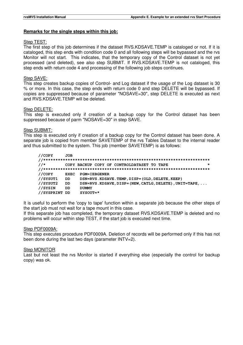
rvsMVS Installation Manual Appendix E. Example for an extended rvs Start Procedure
Remarks for the single steps within this job: Step TEST: The first step of this job determines if the dataset RVS.KDSAVE.TEMP is cataloged or not. If it is cataloged, this step ends with condition code 0 and all following steps will be bypassed and the rvs Monitor will not start. This indicates, that the temporary copy of the Control dataset is not yet processed (and deleted), see also step SUBMIT. If RVS.KDSAVE.TEMP is not cataloged, this step ends with return code 4 and processing of the following job steps continues. Step SAVE: This step creates backup copies of Control- and Log dataset if the usage of the Log dataset is 30 % or more. In this case, the step ends with return code 0 and step DELETE will be bypassed. If copies are suppressed because of parameter "NOSAVE=30", step DELETE is executed as next and RVS.KDSAVE.TEMP will be deleted. Step DELETE: This step is executed only if creation of a backup copy for the Control dataset has been suppressed because of parm "NOSAVE=30" in step SAVE. Step SUBMIT: This step is executed only if creation of a backup copy for the Control dataset has been done. A separate job is copied from member SAVETEMP of the rvs Tables Dataset to the internal reader and thus submitted to the system. This job (member SAVETEMP) is as follows: //COPY JOB
//********************************************************************
//* COPY BACKUP COPY OF CONTROLDATASET TO TAPE *
//********************************************************************
//COPY EXEC PGM=IEBGENER
//SYSUT1 DD DSN=RVS.KDSAVE.TEMP,DISP=(OLD,DELETE,KEEP)
//SYSUT2 DD DSN=RVS.KDSAVE,DISP=(NEW,CATLG,DELETE),UNIT=TAPE,...
//SYSIN DD DUMMY
//SYSPRINT DD SYSOUT=*
It is useful to perform the 'copy to tape' function within a separate job because the other steps of the start job must not wait for a tape mount in this case. If this separate job has completed, the temporary dataset RVS.KDSAVE.TEMP is deleted and no problems will occur within step TEST, if the start job is executed next time. Step PDF0009A: This step executes procedure PDF0009A. Deletion of records will be performed only if this has not been done during the last two days (parameter INTV=2). Step MONITOR Last but not least the rvs Monitor is started if everything else (especially the control for backup copy) was ok.
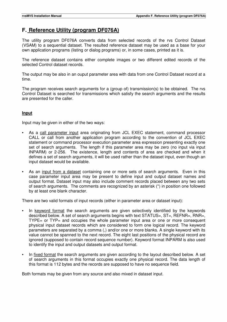
rvsMVS Installation Manual Appendix F. Reference Utility (program DF076A)
F. Reference Utility (program DF076A) The utility program DF076A converts data from selected records of the rvs Control Dataset (VSAM) to a sequential dataset. The resulted reference dataset may be used as a base for your own application programs (listing or dialog programs) or, in some cases, printed as it is. The reference dataset contains either complete images or two different edited records of the selected Control dataset records. The output may be also in an ouput parameter area with data from one Control Dataset record at a time. The program receives search arguments for a (group of) transmission(s) to be obtained. The rvs Control Dataset is searched for transmissions which satisfy the search arguments and the results are presented for the caller. Input Input may be given in either of the two ways: • As a call parameter input area originating from JCL EXEC statement, command processor
CALL or call from another application program according to the convention of JCL EXEC statement or command processor execution parameter area expression presenting exactly one set of search arguments. The length if this parameter area may be zero (no input via input INPARM) or 2-256. The existence, length and contents of area are checked and when it defines a set of search arguments, it will be used rather than the dataset input, even though an input dataset would be available.
• As an input from a dataset containing one or more sets of search arguments. Even in this
case parameter input area may be present to define input and output dataset names and output format. Dataset input may also include comment records placed between any two sets of search arguments. The comments are recognized by an asterisk (*) in position one followed by at least one blank character.
There are two valid formats of input records (either in parameter area or dataset input): • In keyword format the search arguments are given selectively identified by the keywords
described below. A set of search arguments begins with text STATUS=, ST=, REFNR=, RNR=, TYPE= or TYP= and occupies the whole parameter input area or one or more consequent physical input dataset records which are considered to form one logical record. The keyword parameters are separated by a comma (,) and/or one or more blanks. A single keyword with its value cannot be spanned to the next record. The eight last positions of the physical record are ignored (supposed to contain record sequence number). Keyword format INPARM is also used to identify the input and output datasets and output format.
• In fixed format the search arguments are given according to the layout described below. A set
of search arguments in this format occupies exactly one physical record. The data length of this format is 112 bytes and the records are supposed to have no sequence field.
Both formats may be given from any source and also mixed in dataset input.
rvsMVS Installation Manual Appendix F. Reference Utility (program DF076A)
NOTE: If mixing of these two different formats is desired (e.g. by concatenating input files), the LRECL definition have to be taken care of (the fixed format requires LRECL of at least 112 while for the keyword format 80 is sufficient). The DD-name of the input dataset is set to the value of the INFILE keyword parameter or defaulted to SYSIN if the parameter input area is omitted or it contains no valid set of search arguments. Keyword format input parameters: INFILE=ddname Input file DD-name, 1-8 characters (optional) This keyword parameter identifies the DD-name of the dataset which contains the input. Default is SYSIN if there is no parameter input area at all or the value of this keyword is omitted or blank. When this parameter is defined, all keywords other than OUTFILE and FMT should be omitted. This parameter is valid only in call parameter input. The synonym of this parameter is INF. OUTFILE=ddname Output file DD-name, 1-8 characters (optional) This keyword parameter identifies the DD-name of the dataset on which the output will be written. Default is SYSPRINT if the parameter output area is omitted or the input is read from a dataset. The given value must not be SYSOUT. If the dataset is explicitly or implicitly defined as output dataset and the output is written in keyword format (see below), it will also contain error and informational messages unless the dataset SYSOUT or dataset for WTO-messages is available. When this parameter is defined, all keywords other than INFILE and FMT should be omitted. This parameter is valid only in call parameter input. The synonym of this parameter is OUTF. FMT=format Output format, 2 characters (optional) This keyword parameter defines, if needed, the format of the output. The valid values of format are: FX The output is written in fixed format records (see below) which are derived from the
accessed rvs Control Dataset records. KD The output is written as (truncated) rvs Control Dataset records with no editing. If output
goes to parameter output area, the whole record is moved. If output goes to a dataset, the records may be truncated to the record length of the output file.
KW The output is written in keyword format records which are edited from the accessed rvs
Control Dataset records. The data length of the records is 80 bytes. This parameter may be given only in call parameter input. STATUS=status Status of transmission, 1 character (optional) The status of the transmissions to be queried. The value is a single nonblank character according to the list below. This parameter must be given if TYPE is not defined but is exclusive with TYPE.
rvsMVS Installation Manual Appendix F. Reference Utility (program DF076A)
Valid values: S Dataset(s) sent (successfully completed or not). R Dataset(s) received (successfully completed or not). D Dataset(s) due to be sent or received. NOTE: • This parameter is applicable only in keyword format input record. • This parameter may also be expressed by TYPE=*S or TYPE=*R or TYPE=D*. Synonym of this keyword is ST. TYPE=type Type of the record, 2 characters (optional) The record type of the control dataset records to be queried. The value is one two characters long code according to the list below. Also a list of max twelve codes enclosed in parentheses and separated with commas may be given. This parameter must be given if STATUS is not defined but is exclusive with STATUS. AS Active still due to be sent. AR Active still due to be received. AN Active end-to-end response in relay station. A* AS+AR. BS Terminated send transmission. BR Terminated receive transmission. B* BS+BR. CS Successfully completed send transmission. CR Successfully completed receive transmission. C* CS+CR. DS Active, not yet started send transmission. DR Active, not yet started receive transmission. D* DS+DR. RS Resident send transmission. RR Resident receive transmission. R* RS+RR. JA Job active. JC Job completed. J* JA+JC. *S =AS+CS. *R =AR+CR. ** Any record type. Examples : TYPE=B* All abended transmissions TYPE=(AR,AS,C*) active receive + send transmissions and all completed
transmissions Synonym of this keyword is TYP.
rvsMVS Installation Manual Appendix F. Reference Utility (program DF076A)
SID=sid Station identification, 1-3 characters (optional) The station identification of the remote station (sid). If the searched sid is exactly one or two characters long, the value should be followed by a dash (-); otherwise the given sid of one or two characters will be considered as generic. A generic sid may also be an expression with an asterisk (*) at the end of the sid indicating the wildcard character(s). Synonym of this keyword is ORT. DSNAME=dsname Dataset name with or without member name (optional) DSNAME=dsname(member) Name of the searched dataset. If the given dataset name is shorter than the maximum of 44 characters, it will be considered as a generic one. A generic dataset name may also be indicated by an asterisk (*) at the end of the dsname part of the value to indicate the wildcard character(s). If the searched dataset name should be of the same length as the given dsname part of the value of 43 characters or shorter, a dash (-) should follow the dsname. If the dataset is partitioned and a member name is given, it must be enclosed in parentheses and follow immediately the dataset name as described above. The maximum length of the member name is 8 characters and the maximum length of the entire value is 54 characters. Generic member names are not recognized. QTM=yydddhhmmsst Queuing date and time, 1-12 numeric characters (optional) Queuing date and time of the transmissions to be queried. yy is year, ddd day number, hh hours, mm minutes, ss seconds and t tenths of second. The value may also be truncated to the right to define a time interval, when only the given digits are considered as (part of) search argument. If this keyword is given, QDATE, QDAY or QTIME must be omitted in the same set of search arguments. Examples :
QTM=9413811 looks for transmissions queued from 11:00 to 11:59 in 18.05.1994
QTM=92138112341 looks for transmissions queued at 11:23:41 in 17.05.1992 QDATE=date1-date2 Queuing date(s), (optional) QDATE=*-nrofdays One or two dates to limit the queuing time frame in days of the queried transmission(s). The explicitly given dates have format yy.ddd or simply ddd but even the more natural and self-explanatory form of dates dd.mm.yy is allowed. Two given dates must be separated by a dash (-) and be both in either 'day-number' or 'natural' format.
yy = year, 2 digits ddd = day number within the year, 3 digits mm = month, 2 digits dd = day within the month, 2 digits
In explicitly given date definitions the given 'date1' must not be later than the given 'date2'. The given 'date2' may be omitted and will then be defaulted equal to the 'date1'.
rvsMVS Installation Manual Appendix F. Reference Utility (program DF076A)
If in 'ddd' format the given day number is greater than the current machine day number, the year is defaulted to the previous one. Examples (current machine date is 94.138, that is 18.05.94): expression equals to interval QDATE=065 06.03.94 - 06.03.94 QDATE=140-365 20.05.93 - 31.12.93 QDATE=139-108 19.05.93 - 18.05.94 QDATE=94.110-365 20.05.94 - 31.12.94 If there is an asterisk (*) in place of 'date1', the dates are defaulted to the current machine date. If the asterisk is followed by a minus (-) sign 'nrofdays' (number of days, one to three digits), the 'date1' is replaced by the date given number of days before the current machine date. Examples (current machine date is 94.108, that is 18.05.94): expression equals to interval QDATE=* 18.05.94 - 18.05.94 QDATE=*-3 15.05.94 - 18.05.94 QDATE=*-240 11.08.93 - 18.05.94 If this keyword is given, QTM or QDAY must be omitted in the same set of search arguments. QDAY=date-nrofdays Queuing date(s), (optional) QDAY=date+nrofdays QDAY=*-nrofdays One date and a number of days to limit the queuing time interval in days of the queried transmission(s). The explicitly given date has format yy.ddd or simply ddd or even the more natural and self-explanatory form of date dd.mm.yy. The nrofdays (number of days) is separated by a minus (-) or a plus (+) to indicate the other limiting date nrofdays before or after the given date.
yy = year, 2 digits ddd = day number within the year, 3 digits mm = month, 2 digits dd = day within the month, 2 digits nrofdays = number of days, 1-3 digits
If in 'ddd' format the given day number is greater than the current machine day number, the year is defaulted to the previous one. Examples (current machine date is 94.138, that is 18.05.94): expression equals to interval QDAY=065 06.03.94 - 06.03.94 QDAY=140+365 20.05.93 - 19.05.94 QDAY=138-108 18.05.93 - 31.12.93 QDAY=94.138-365 18.05.93 - 18.05.94 If there is an asterisk (*) in place of 'date', it is defaulted to the current machine date.
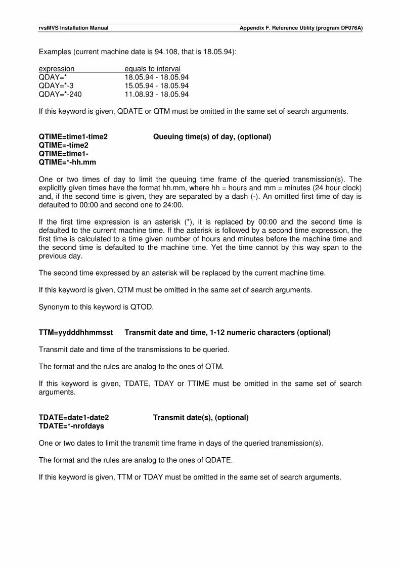
rvsMVS Installation Manual Appendix F. Reference Utility (program DF076A)
Examples (current machine date is 94.108, that is 18.05.94): expression equals to interval QDAY=* 18.05.94 - 18.05.94 QDAY=*-3 15.05.94 - 18.05.94 QDAY=*-240 11.08.93 - 18.05.94 If this keyword is given, QDATE or QTM must be omitted in the same set of search arguments. QTIME=time1-time2 Queuing time(s) of day, (optional) QTIME=-time2 QTIME=time1- QTIME=*-hh.mm One or two times of day to limit the queuing time frame of the queried transmission(s). The explicitly given times have the format hh.mm, where hh = hours and mm = minutes (24 hour clock) and, if the second time is given, they are separated by a dash (-). An omitted first time of day is defaulted to 00:00 and second one to 24:00. If the first time expression is an asterisk (*), it is replaced by 00:00 and the second time is defaulted to the current machine time. If the asterisk is followed by a second time expression, the first time is calculated to a time given number of hours and minutes before the machine time and the second time is defaulted to the machine time. Yet the time cannot by this way span to the previous day. The second time expressed by an asterisk will be replaced by the current machine time. If this keyword is given, QTM must be omitted in the same set of search arguments. Synonym to this keyword is QTOD. TTM=yydddhhmmsst Transmit date and time, 1-12 numeric characters (optional) Transmit date and time of the transmissions to be queried. The format and the rules are analog to the ones of QTM. If this keyword is given, TDATE, TDAY or TTIME must be omitted in the same set of search arguments. TDATE=date1-date2 Transmit date(s), (optional) TDATE=*-nrofdays One or two dates to limit the transmit time frame in days of the queried transmission(s). The format and the rules are analog to the ones of QDATE. If this keyword is given, TTM or TDAY must be omitted in the same set of search arguments.
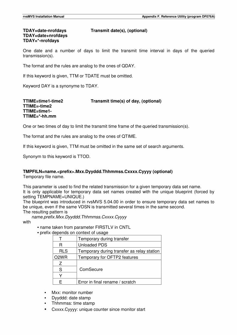
rvsMVS Installation Manual Appendix F. Reference Utility (program DF076A)
TDAY=date-nrofdays Transmit date(s), (optional) TDAY=date+nrofdays TDAY=*-nrofdays One date and a number of days to limit the transmit time interval in days of the queried transmission(s). The format and the rules are analog to the ones of QDAY. If this keyword is given, TTM or TDATE must be omitted. Keyword DAY is a synonyme to TDAY. TTIME=time1-time2 Transmit time(s) of day, (optional) TTIME=-time2 TTIME=time1- TTIME=*-hh.mm One or two times of day to limit the transmit time frame of the queried transmission(s). The format and the rules are analog to the ones of QTIME. If this keyword is given, TTM must be omitted in the same set of search arguments. Synonym to this keyword is TTOD. TMPFILN=name.<prefix>.Mxx.Dyyddd.Thhmmss.Cxxxx.Cyyyy (optional) Temporary file name. This parameter is used to find the related transmission for a given temporary data set name. It is only applicable for temporary data set names created with the unique blueprint (forced by setting TEMPNAME=UNIQUE.) The blueprint was introduced in rvsMVS 5.04.00 in order to ensure temporary data set names to be unique, even if the same VDSN is transmitted several times in the same second. The resulting pattern is name.prefix.Mxx.Dyyddd.Thhmmss.Cxxxx.Cyyyy with
• name taken from parameter FIRSTLV in CNTL • prefix depends on context of usage
T Temporary during transfer
R Unloaded PDS
RLS Temporary during transfer as relay station
O2WR Temporary for OFTP2 features
Z
ComSecure
S
Y
E Error in final rename / scratch
• Mxx: monitor number • Dyyddd: date stamp • Thhmmss: time stamp
• Cxxxx.Cyyyy: unique counter since monitor start
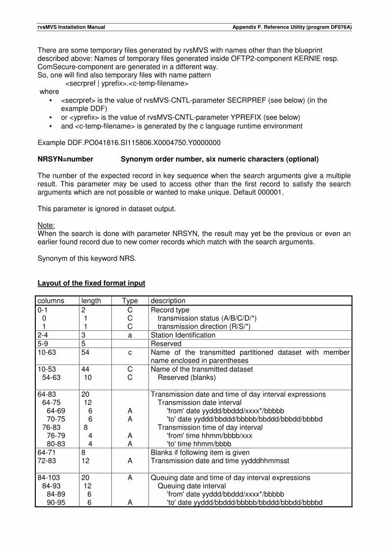
rvsMVS Installation Manual Appendix F. Reference Utility (program DF076A)
There are some temporary files generated by rvsMVS with names other than the blueprint described above: Names of temporary files generated inside OFTP2-component KERNIE resp. ComSecure-component are generated in a different way. So, one will find also temporary files with name pattern <secrpref | yprefix>.<c-temp-filename> where
• <secrpref> is the value of rvsMVS-CNTL-parameter SECRPREF (see below) (in the example DDF)
• or <yprefix> is the value of rvsMVS-CNTL-parameter YPREFIX (see below) • and <c-temp-filename> is generated by the c language runtime environment
Example DDF.PO041816.SI115806.X0004750.Y0000000 NRSYN=number Synonym order number, six numeric characters (optional) The number of the expected record in key sequence when the search arguments give a multiple result. This parameter may be used to access other than the first record to satisfy the search arguments which are not possible or wanted to make unique. Default 000001. This parameter is ignored in dataset output. Note: When the search is done with parameter NRSYN, the result may yet be the previous or even an earlier found record due to new comer records which match with the search arguments. Synonym of this keyword NRS. Layout of the fixed format input
columns length Type description
0-1 0 1
2 1 1
C C C
Record type transmission status (A/B/C/D/*) transmission direction (R/S/*)
2-4 3 a Station Identification 5-9 5 Reserved 10-63 54 c Name of the transmitted partitioned dataset with member
name enclosed in parentheses 10-53 54-63
44 10
C C
Name of the transmitted dataset Reserved (blanks)
64-83 64-75 64-69 70-75 76-83 76-79 80-83
20 12 6 6 8 4 4
A A
A A
Transmission date and time of day interval expressions Transmission date interval 'from' date yyddd/bbddd/xxxx*/bbbbb 'to' date yyddd/bbddd/bbbbb/bbddd/bbbdd/bbbbd Transmission time of day interval 'from' time hhmm/bbbb/xxx 'to' time hhmm/bbbb
64-71 72-83
8 12
A
Blanks if following item is given Transmission date and time yydddhhmmsst
84-103 84-93 84-89 90-95
20 12 6 6
A
A
Queuing date and time of day interval expressions Queuing date interval 'from' date yyddd/bbddd/xxxx*/bbbbb 'to' date yyddd/bbddd/bbbbb/bbddd/bbbdd/bbbbd
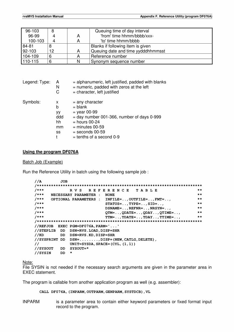
rvsMVS Installation Manual Appendix F. Reference Utility (program DF076A)
96-103 96-99 100-103
8 4 4
A A
Queuing time of day interval 'from' time hhmm/bbbb/xxx- 'to' time hhmm/bbbb
84-81 92-103
8 12
A
Blanks if following item is given Queuing date and time yydddhhmmsst
104-109 6 A Reference number 110-115 6 N Synonym sequence number
Legend: Type: A = alphanumeric, left justified, padded with blanks N = numeric, padded with zeros at the left C = character, left justified Symbols: x = any character b = blank yy = year 00-99 ddd = day number 001-366, number of days 0-999 hh = hours 00-24 mm = minutes 00-59 ss = seconds 00-59 t = tenths of a second 0-9 Using the program DF076A Batch Job (Example) Run the Reference Utility in batch using the following sample job : //A JOB
/**********************************************************************
/*** R V S R E F E R E N C E T A B L E **
/*** NECESSARY PARAMETER : NONE **
/*** OPTIONAL PARAMETERS : INFILE=..,OUTFILE=..,FMT=.., **
/*** STATUS=..,TYPE=..,SID=.., **
/*** DSNAME=..,REFNR=..,NRSYN=.., **
/*** QTM=..,QDATE=..,QDAY..,QTIME=.., **
/*** TTM=..,TDATE=..,TDAY..,TTIME=.., **
/**********************************************************************
//REFJOB EXEC PGM=DF076A,PARM='...'
//STEPLIB DD DSN=RVS.LOAD,DISP=SHR
//KD DD DSN=RVS.KD,DISP=SHR
//SYSPRINT DD DSN=........,DISP=(NEW,CATLG,DELETE),
// UNIT=SYSDA,SPACE=(CYL,(1,1))
//SYSOUT DD SYSOUT=*
//SYSIN DD *
Note: File SYSIN is not needed if the necessary search arguments are given in the parameter area in EXEC statement. The program is callable from another application program as well (e.g. assembler):
CALL DF076A,(INPARM,OUTPARM,GENPARM,SYSTDCB),VL
INPARM is a parameter area to contain either keyword parameters or fixed format input
record to the program.
rvsMVS Installation Manual Appendix F. Reference Utility (program DF076A)
OUTPARM is a parameter area to contain the response from the program after the
execution. This area must be large enough for the output; otherwise the result is unpredictable.
GENPARM is the rvs general parameter area when it is available. SYSTDCB is an area which contains an opened DCB for SYSOUT dataset. Note: • One or more call parameters may be omitted but if OUTPARM is defined, INPARM must also
be defined. • Two or more call parameters are applicable only at a call from another application program. Further the program is callable from the command processor (TSO): XCALL CALL 'DF076A' '...'
Process The input, output and formats are determined. If the search arguments are read from a dataset, it is opened. If the output is written to a dataset, it is opened. An effort is made to access the rvs SYSWTO dataset or alternatively to open dataset SYSOUT. The input is read and analyzed one set of search arguments at a time. If the input is a dataset, both formats (keyword and fixed) may be mixed provided that the record length is sufficient. The Control Dataset is searched for records to satisfy the given search arguments using a key which is built as far as possible of the given information. The rest of the search arguments are matched by the program code. If no meaningful key can be built from the search arguments, the search is made with sequential read through the dataset. The result is presented to the caller and the return code is set.
rvsMVS Installation Manual Appendix F. Reference Utility (program DF076A)
Output The output from the program is written either to the output parameter area if it is provided or to the output dataset. If the output is written to the output parameter area, it is the caller's responsibility to define the length of the area sufficient to contain the output record. The error and informational messages are written preferably to the SYSWTO dataset amongst the other similar messages. If it is not possible, the output is written to SYSOUT or output dataset. If there is a parameter area for SYSOUT dataset DCB, the dataset should be opened. If the parameter area is not provided, an attempt is made to open the SYSOUT as well. In either way, the error and informational messages are written to this dataset. If the output is written to a dataset in keyword format and no SYSOUT dataset is available, the messages are written to the output dataset. If no access to SYSOUT dataset is possible and the output is not written in keyword format, the writing of error and informational messages is suppressed. If OUTPARM is defined, the input is expected from INPARM as well. If the output datasets are allocated as new and DCB information is not complete, the program makes following defaulting: - For output dataset in:
- keyword format LRECL=80, BLKSIZE=80 and RECFM=FBA, - fixed format LRECL=512, BLKSIZE=7680 and RECFM=FB, - KD record format LRECL=590, BLKSIZE=6490 and RECFM=FB.
- For SYSOUT dataset LRECL=80, BLKSIZE=80, RECFM=FBA and MACRF=PL. For both output datasets DSORG=PS is mandatory. If the output dataset DCB information is provided from any source to the program, following should be noted: - M or A control character may be specified in keyword format output. - LRECL must be 80 or higher and it should be equal to or higher than the respective default for
each format above, otherwise the output records are truncated. For SYSOUT dataset following should be noted: - M or A control character may be specified. - LRECL must be 80 or higher. - If the DCB is provided as a parameter, also MACRF=PM may be defined. There are three different output formats: - Keyword format Some information from the Control Dataset records is edited to
a printable form. - Control Dataset record format The records retrieved from the Control Dataset are presented
unedited. - Fixed format Most of the information from the Control Dataset records is
edited to a printable form.
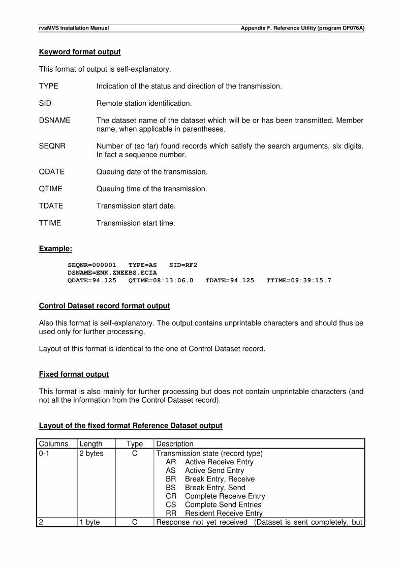
rvsMVS Installation Manual Appendix F. Reference Utility (program DF076A)
Keyword format output This format of output is self-explanatory. TYPE Indication of the status and direction of the transmission. SID Remote station identification. DSNAME The dataset name of the dataset which will be or has been transmitted. Member
name, when applicable in parentheses. SEQNR Number of (so far) found records which satisfy the search arguments, six digits.
In fact a sequence number. QDATE Queuing date of the transmission. QTIME Queuing time of the transmission. TDATE Transmission start date. TTIME Transmission start time. Example:
SEQNR=000001 TYPE=AS SID=RF2
DSNAME=ENK.ZNEEBS.ECIA
QDATE=94.125 QTIME=08:13:06.0 TDATE=94.125 TTIME=09:39:15.7
Control Dataset record format output Also this format is self-explanatory. The output contains unprintable characters and should thus be used only for further processing. Layout of this format is identical to the one of Control Dataset record. Fixed format output This format is also mainly for further processing but does not contain unprintable characters (and not all the information from the Control Dataset record). Layout of the fixed format Reference Dataset output
Columns Length Type Description
0-1 2 bytes C Transmission state (record type) AR Active Receive Entry AS Active Send Entry BR Break Entry, Receive BS Break Entry, Send CR Complete Receive Entry CS Complete Send Entries RR Resident Receive Entry
2 1 byte C Response not yet received (Dataset is sent completely, but
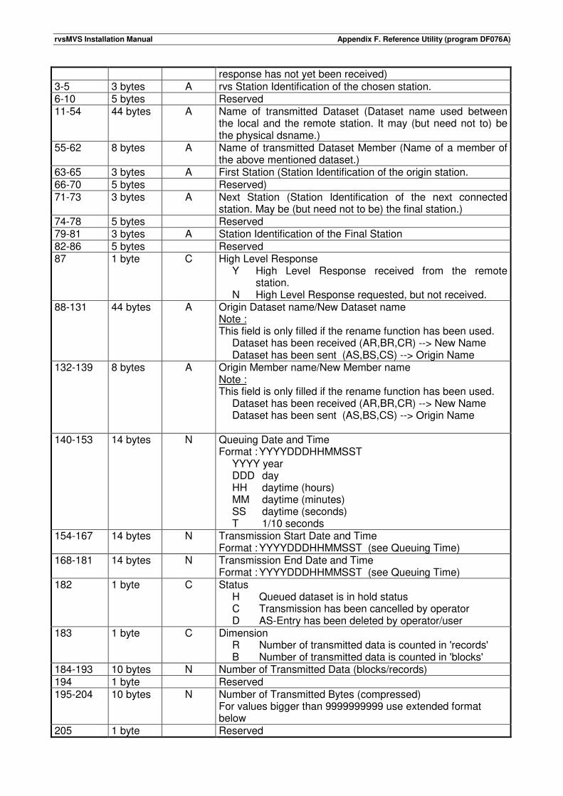
rvsMVS Installation Manual Appendix F. Reference Utility (program DF076A)
response has not yet been received) 3-5 3 bytes A rvs Station Identification of the chosen station. 6-10 5 bytes Reserved 11-54 44 bytes A Name of transmitted Dataset (Dataset name used between
the local and the remote station. It may (but need not to) be the physical dsname.)
55-62 8 bytes A Name of transmitted Dataset Member (Name of a member of the above mentioned dataset.)
63-65 3 bytes A First Station (Station Identification of the origin station. 66-70 5 bytes Reserved) 71-73 3 bytes A Next Station (Station Identification of the next connected
station. May be (but need not to be) the final station.) 74-78 5 bytes Reserved 79-81 3 bytes A Station Identification of the Final Station 82-86 5 bytes Reserved 87 1 byte C High Level Response
Y High Level Response received from the remote station.
N High Level Response requested, but not received. 88-131 44 bytes A Origin Dataset name/New Dataset name
Note : This field is only filled if the rename function has been used. Dataset has been received (AR,BR,CR) --> New Name Dataset has been sent (AS,BS,CS) --> Origin Name
132-139 8 bytes A Origin Member name/New Member name Note : This field is only filled if the rename function has been used. Dataset has been received (AR,BR,CR) --> New Name Dataset has been sent (AS,BS,CS) --> Origin Name
140-153 14 bytes N Queuing Date and Time Format : YYYYDDDHHMMSST YYYY year DDD day HH daytime (hours) MM daytime (minutes) SS daytime (seconds) T 1/10 seconds
154-167 14 bytes N Transmission Start Date and Time Format : YYYYDDDHHMMSST (see Queuing Time)
168-181 14 bytes N Transmission End Date and Time Format : YYYYDDDHHMMSST (see Queuing Time)
182 1 byte C Status H Queued dataset is in hold status C Transmission has been cancelled by operator D AS-Entry has been deleted by operator/user
183 1 byte C Dimension R Number of transmitted data is counted in 'records' B Number of transmitted data is counted in 'blocks'
184-193 10 bytes N Number of Transmitted Data (blocks/records) 194 1 byte Reserved 195-204 10 bytes N Number of Transmitted Bytes (compressed)
For values bigger than 9999999999 use extended format below
205 1 byte Reserved
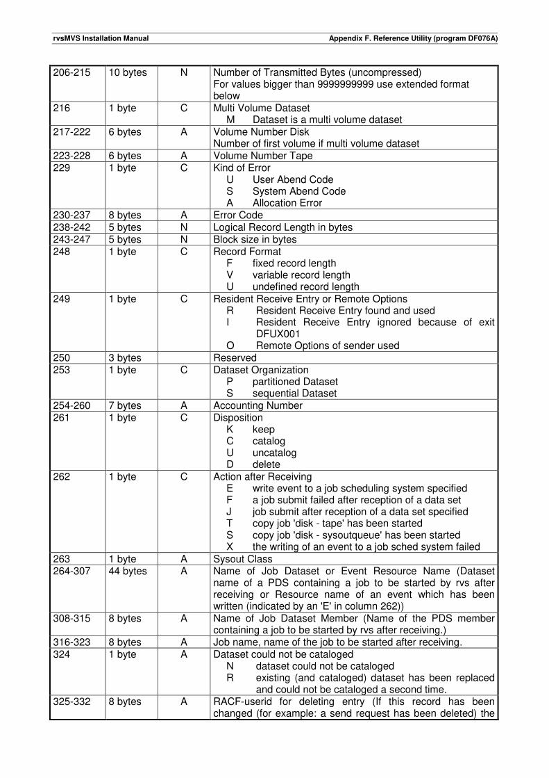
rvsMVS Installation Manual Appendix F. Reference Utility (program DF076A)
206-215 10 bytes N Number of Transmitted Bytes (uncompressed) For values bigger than 9999999999 use extended format below
216 1 byte C Multi Volume Dataset M Dataset is a multi volume dataset
217-222 6 bytes A Volume Number Disk Number of first volume if multi volume dataset
223-228 6 bytes A Volume Number Tape 229 1 byte C Kind of Error
U User Abend Code S System Abend Code A Allocation Error
230-237 8 bytes A Error Code 238-242 5 bytes N Logical Record Length in bytes 243-247 5 bytes N Block size in bytes 248 1 byte C Record Format
F fixed record length V variable record length U undefined record length
249 1 byte C Resident Receive Entry or Remote Options R Resident Receive Entry found and used I Resident Receive Entry ignored because of exit
DFUX001 O Remote Options of sender used
250 3 bytes Reserved 253 1 byte C Dataset Organization
P partitioned Dataset S sequential Dataset
254-260 7 bytes A Accounting Number 261 1 byte C Disposition
K keep C catalog U uncatalog D delete
262 1 byte C Action after Receiving E write event to a job scheduling system specified F a job submit failed after reception of a data set J job submit after reception of a data set specified T copy job 'disk - tape' has been started S copy job 'disk - sysoutqueue' has been started X the writing of an event to a job sched system failed
263 1 byte A Sysout Class 264-307 44 bytes A Name of Job Dataset or Event Resource Name (Dataset
name of a PDS containing a job to be started by rvs after receiving or Resource name of an event which has been written (indicated by an 'E' in column 262))
308-315 8 bytes A Name of Job Dataset Member (Name of the PDS member containing a job to be started by rvs after receiving.)
316-323 8 bytes A Job name, name of the job to be started after receiving. 324 1 byte A Dataset could not be cataloged
N dataset could not be cataloged R existing (and cataloged) dataset has been replaced
and could not be cataloged a second time. 325-332 8 bytes A RACF-userid for deleting entry (If this record has been
changed (for example: a send request has been deleted) the
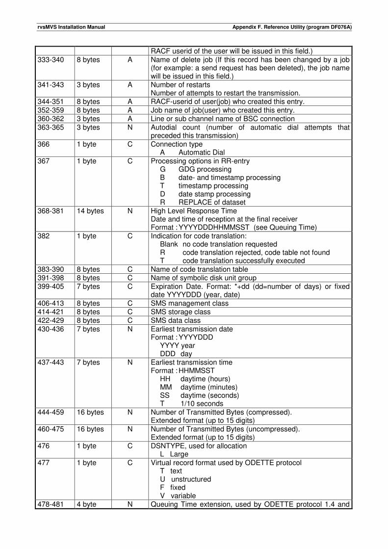
rvsMVS Installation Manual Appendix F. Reference Utility (program DF076A)
RACF userid of the user will be issued in this field.) 333-340 8 bytes A Name of delete job (If this record has been changed by a job
(for example: a send request has been deleted), the job name will be issued in this field.)
341-343 3 bytes A Number of restarts Number of attempts to restart the transmission.
344-351 8 bytes A RACF-userid of user(job) who created this entry. 352-359 8 bytes A Job name of job(user) who created this entry. 360-362 3 bytes A Line or sub channel name of BSC connection 363-365 3 bytes N Autodial count (number of automatic dial attempts that
preceded this transmission) 366 1 byte C Connection type
A Automatic Dial 367 1 byte C Processing options in RR-entry
G GDG processing B date- and timestamp processing T timestamp processing D date stamp processing R REPLACE of dataset
368-381 14 bytes N High Level Response Time Date and time of reception at the final receiver Format : YYYYDDDHHMMSST (see Queuing Time)
382 1 byte C Indication for code translation: Blank no code translation requested R code translation rejected, code table not found T code translation successfully executed
383-390 8 bytes C Name of code translation table 391-398 8 bytes C Name of symbolic disk unit group 399-405 7 bytes C Expiration Date. Format: *+dd (dd=number of days) or fixed
date YYYYDDD (year, date) 406-413 8 bytes C SMS management class 414-421 8 bytes C SMS storage class 422-429 8 bytes C SMS data class 430-436 7 bytes N Earliest transmission date
Format : YYYYDDD YYYY year DDD day
437-443 7 bytes N Earliest transmission time Format : HHMMSST HH daytime (hours) MM daytime (minutes) SS daytime (seconds) T 1/10 seconds
444-459 16 bytes N Number of Transmitted Bytes (compressed). Extended format (up to 15 digits)
460-475 16 bytes N Number of Transmitted Bytes (uncompressed). Extended format (up to 15 digits)
476 1 byte C DSNTYPE, used for allocation L Large
477 1 byte C Virtual record format used by ODETTE protocol T text U unstructured F fixed V variable
478-481 4 byte N Queuing Time extension, used by ODETTE protocol 1.4 and
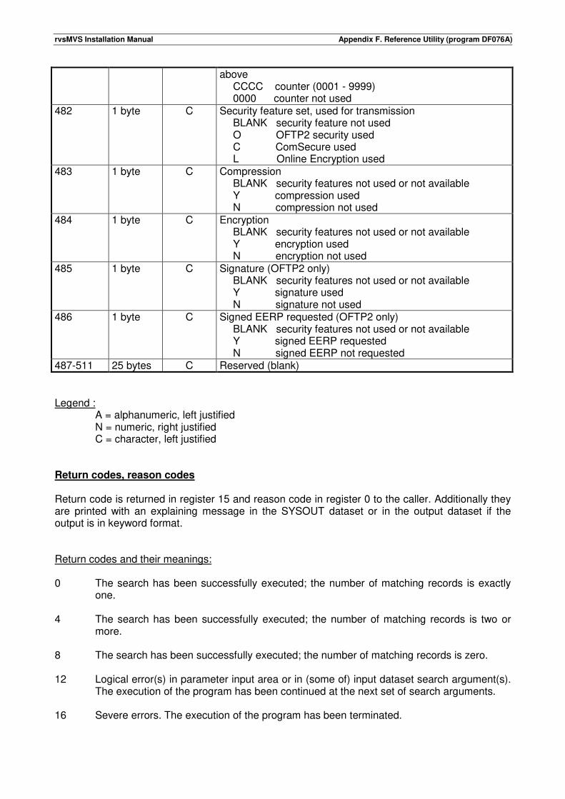
rvsMVS Installation Manual Appendix F. Reference Utility (program DF076A)
above CCCC counter (0001 - 9999) 0000 counter not used
482 1 byte C Security feature set, used for transmission BLANK security feature not used O OFTP2 security used C ComSecure used L Online Encryption used
483 1 byte C Compression BLANK security features not used or not available Y compression used N compression not used
484 1 byte C Encryption BLANK security features not used or not available Y encryption used N encryption not used
485 1 byte C Signature (OFTP2 only) BLANK security features not used or not available Y signature used N signature not used
486 1 byte C Signed EERP requested (OFTP2 only) BLANK security features not used or not available Y signed EERP requested N signed EERP not requested
487-511 25 bytes C Reserved (blank)
Legend :
A = alphanumeric, left justified N = numeric, right justified C = character, left justified
Return codes, reason codes Return code is returned in register 15 and reason code in register 0 to the caller. Additionally they are printed with an explaining message in the SYSOUT dataset or in the output dataset if the output is in keyword format. Return codes and their meanings: 0 The search has been successfully executed; the number of matching records is exactly
one. 4 The search has been successfully executed; the number of matching records is two or
more. 8 The search has been successfully executed; the number of matching records is zero. 12 Logical error(s) in parameter input area or in (some of) input dataset search argument(s).
The execution of the program has been continued at the next set of search arguments. 16 Severe errors. The execution of the program has been terminated.
rvsMVS Installation Manual Appendix F. Reference Utility (program DF076A)
Reason codes: 00 Parameter record missing in the Control Dataset. 04 Read error in the Control Dataset. 08 Invalid set of search arguments, no start found. 12 Unidentified keyword. 16 Illegal search argument value. 20 Invalid search argument value length. 24 Conflicting search arguments. 28 Syntax error in search arguments. Abend codes: 760 Invalid length of parameter input area. 761 Parameter output area defined, no parameter input area. 762 Input/output dataset needed but could not be opened. 769 Illegal output dataset DCB parameters.

rvsMVS Installation Manual Appendix F. Reference Utility (program DF076A)
This page will be intentionally empty.
rvsMVS Installation Manual Appendix G. Using the 'Remote Operating Function'
G. Using the 'Remote Operating Function' The 'Remote Operating Function' allows to perform rvs operating from any 3270 screen. After logon to the rvs monitor, all rvs commands may be entered from the screen, except commands of the form 'f-rvs', for example 'P-rvs'. Additional, all rvs messages which are displayed on console will be sent to the screen. The following sections describe all details for the use of this function. Layout of the 3270 screen when using the remote operating function rvs assumes to work with a screen with 24 rows and 80 columns. After an SNA session to rvs has been established, the screen will be cleared. The first row is always used as an input field. If any input data are entered (for example rvs commands), the input data must start in column 1. The second row remains blank. All other rows are used for display of rvs messages. Writing of messages to these rows is done in a wrap around mode. The last displayed message is always followed by a line consisting of characters "-". All rvs messages which are displayed on the screen are preceded by the sequence ")sid", where "sid" denotes the rvs station name of the local rvs installation. In some cases, the 7th byte of the rvs message identifier is changed to the character "Q", for example DF3000I is changed to DF3000Q. Logon from a 3270 screen to the rvs monitor A logon request to rvs is initiated if the sequence LOGON APPLID(name) DATA(OPER)
is entered from the screen. "name" denotes the application id which is used for this function. The application id must be defined within VTAM, "name" must be the same value as specified within the rvs start parameter "RMOPAPPL". If the logon request is successful (an SNA session has been established), an initial message will be sent to the screen (this message is starting with the characters "P rvs ", followed by the release number and the rvs station name of the local rvs installation and some other values). This initial message is followed by the message: )sid ENTER PASSWORD
The logon password must now be entered (row 1, column 1). This password is the same as described in the section 'Installation of rvs ISPF panels' within this manual. The password is not displayed on the screen. If the valid password has been entered, the message )sid LOGON COMPLETE
rvsMVS Installation Manual Appendix G. Using the 'Remote Operating Function'
will be displayed and the remote operating function will start working (display of messages, processing of rvs commands, see below). This session may be stopped at any time if "LOGOFF" is entered in the input field (starting at column 1). If an invalid password has been entered, the message )sid INVALID PASSWORD, REENTER
will be displayed. If four invalid passwords are entered within one sequence the SNA session will be closed by rvs and a new logon is required. If the logon request is not successful (an SNA session between rvs and the logical unit of the screen could not be established), the following points should be checked in order to determine the reason of this: • The specified application id of the logon request is invalid or the application id is not defined
within VTAM or some cross domain resources are missing or incorrect. • The application is not active (the rvs monitor is not active or the remote operating control task
has not been started (see rvs command "A-RMOP" within the Operation Manual). • The remote operating function is not defined within rvs, this means the rvs start parameter
"RMOPAPPL" has not been specified. • The maximum number of parallel remote operating sessions is exceeded. Starting with release
2.5, the maximum number of parallel remote operator sessions has been extended from 1 to 8 sessions.
Entering rvs commands from the screen If the logon procedure to the rvs monitor is complete, all rvs commands may be entered from the screen, except commands of the form 'f-rvs', for example 'P-rvs'. The syntax of the rvs commands is the same as described within the rvs Operations Manual, but all commands must be preceded by the character "$", for example "$A-094" must be entered if the BSC line (sub channel 094) shall be activated. There are some special commands which are valid only in conjunction with the remote operating function (if entered from the screen): $OP ON Initiates the function to process rvs commands (this command is executed
automatically after logon processing, it must be entered only if the command "$OP OFF" has been entered before).
$RMSG ON Initiates the function to display rvs messages on the screen (this command is
executed automatically after logon processing, it must be entered only if the command "$RMSG OFF" has been entered before).
$OP OFF Stops the function to process rvs commands which are entered from the screen and
stops display of rvs messages on the screen. If this command has been entered and processing of commands (display of messages) shall be reinitialized, both commands ($OP ON and $RMSG ON) must be entered.
$RMSG OFF Stops the function to display rvs messages on the screen. To reinitiate this function,
the command $RMSG ON must be entered. $RMSG ONP Same as command $RMSG ON. Additional, all "print only" messages (messages
which are not displayed on console but only in the rvs job log) will be displayed on the screen. To stop display of "print only" messages (but not display of others), the commands $RMSG OFF and $RMSG ON must be entered.
rvsMVS Installation Manual Appendix G. Using the 'Remote Operating Function'
LOGOFF Terminates the remote operating session. PF1-KEY Pressing of PF1 on the 3270 keyboard results in stopping of message display on
the screen (same as command $RMSG OFF). But in difference to the $RMSG OFF command, reinitiating of the message display function will be done automatically if any input data are entered from the screen.
PF2-PF11 and PF13-PF24
Pressing of PF2 - PF11 or PF13 - PF24 on the 3270 keyboard simulated command entry. The processing is the same as if you hat typed the character string in the command line and pressed the ENTER key (attention - § commands are immediate commands).
PF12-KEY Repeatedly entering PF12 causes the commands most recently entered from the
command field, to be displayed on the command line. The commands are displayed one at time, in reverse sequence to which they were entered (last-in, first-out). This allows you to easily recall a command for resubmission from command field. You can edit the command before entering it if you wish.
PFxx Changing the default PFK settings (PFKEYS member in TABLES file) temporary.
Permanent changes you must do by EDIT command of TSO or ISPF. PFL Display all PF keys settings. PFLxx Display setting of PF key xx. PFLxxyy Display settings of PF keys xx to yy. PFL$ Display settings all $ commands (indirect commands). PFL§ Display settings all § commands (direct commands). PFxx % Reset setting of PF key xx.

rvsMVS Installation Manual Appendix G. Using the 'Remote Operating Function'
This page will be intentionally empty.
rvsMVS Installation Manual Appendix H. rvsMVS Tables
H. rvsMVS Tables H.1. rvsMVS Program Profile Table (only used for the BSC component) The internal Program Profile Table contains a number of standard entries corresponding to the supported FTP's. In addition to these fixed profiles, some special profiles can be added using the dataset RVS.TABLES(PROGPROF). Special program profiles are necessary for example for BTAM leased lines. The name of the user defined profile must be defined within the rvs Stations Table by the parameter 'PPROF': PPROF=ppname with ppname = 3 char. The name of the program profile is free selectable but must not start with a '$'. A program profile is assigned to each entry (station or line) of the stations table which is defined to use BTAM/BSC line(s). This assignment is done during start of the rvs monitor. A program profile, which is assigned to a line entry of the stations table, is used only during activation of the line (command "A lll", see Operation Manual). The only information of the program profile which is used in this case is • the name of the line control program (column 5 - 12) and • the definition how the identification phase shall be done after a line connection is established
(column 72). All other information will be taken from the program profile, which is assigned to the stations entry for the remote station (at the time when this other information is needed, rvs already knows the station id of the remote station because the identification phase is already complete). Each line of the program profile table defines one program profile. Lines with a "*" in column 1 are treated as comment. The following fields are included within a program profile:
Column Description
1 - 3 Name of the program profile (alphanumeric, free selectable). This name is used only for reference to the rvs Stations Table, see parameter "PROGPROF". The names of program profiles must be unique within this table. For test purposes, the program profile for station "sid" may be changed within the rvs monitor by entering the command "F sid,PP=prf", where "prf" is the name of another program profile of the profile table (see Operations Manual).
5 - 12 Module name of the line control program. The specified module name is only used during activation of a BSC line (command "A-lll", "A sid" or "A sid,lll", see Operations Manual). "DF056B00" must be specified for leased lines and for stations connected via a leased line. Additional, this value must be specified for • switched lines if at least one of the remote stations (using this line) has
installed rvs-DOS Release 2. • remote stations which have installed rvs-DOS Release 2. "DF055A00" must
be specified in all other cases. Remark: Module DF055A00 includes support for autodial and password exchange functions, module DF056B00 does not include this support. Thus the following restriction should be noticed:
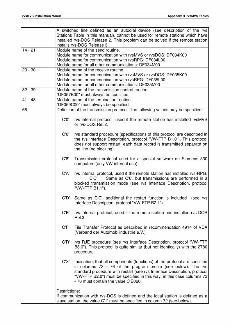
rvsMVS Installation Manual Appendix H. rvsMVS Tables
A switched line defined as an autodial device (see description of the rvs Stations Table in this manual), cannot be used for remote stations which have installed rvs-DOS Release 2. This problem can be solved if the remote station installs rvs-DOS Release 3.
14 - 21 Module name of the send routine. Module name for communication with rvsMVS or rvsDOS: DF034K00 Module name for communication with rvsRPG: DF034L00 Module name for all other communications: DF034M00
23 - 30 Module name of the receive routine. Module name for communication with rvsMVS or rvsDOS: DF035K00 Module name for communication with rvsRPG: DF035L00 Module name for all other communications: DF035M00
32 - 39 Module name of the transmission control routine. "DF057B00" must always be specified.
41 - 48 Module name of the termination routine. "DF059C00" must always be specified.
68 Definition of the transmission protocol. The following values may be specified: C'0' rvs internal protocol, used if the remote station has installed rvsMVS
or rvs-DOS Rel.2. C'6' rvs standard procedure (specifications of this protocol are described in
the rvs Interface Description, protocol "VW-FTP B1.0"). This protocol does not support restart, each data record is transmitted separate on the line (no blocking).
C'8' Transmission protocol used for a special software on Siemens 330
computers (only VW internal use). C'A' rvs internal protocol, used if the remote station has installed rvs-RPG.
C'C' Same as C'6', but transmissions are performed in a blocked transmission mode (see rvs Interface Description, protocol "VW-FTP B1.1").
C'D' Same as C'C', additional the restart function is included (see rvs
Interface Description, protocol "VW-FTP B2.1"). C'E' rvs internal protocol, used if the remote station has installed rvs-DOS
Rel.3. C'F' File Transfer Protocol as described in recommendation 4914 of VDA
(Verband der Automobilindustrie e.V.) C'R' rvs RJE procedure (see rvs Interface Description, protocol "VW-FTP
B3.0"). This protocol is quite similar (but not identically) with the 2780 procedure.
C'X' Indication, that all components (functions) of the protocol are specified
in columns 73 - 76 of the program profile (see below). The rvs standard procedure with restart (see rvs Interface Description, protocol "VW-FTP B2.0") must be specified in this way, in this case columns 73 - 76 must contain the value C'E060'.
Restrictions: If communication with rvs-DOS is defined and the local station is defined as a slave station, the value C'1' must be specified in column 72 (see below).
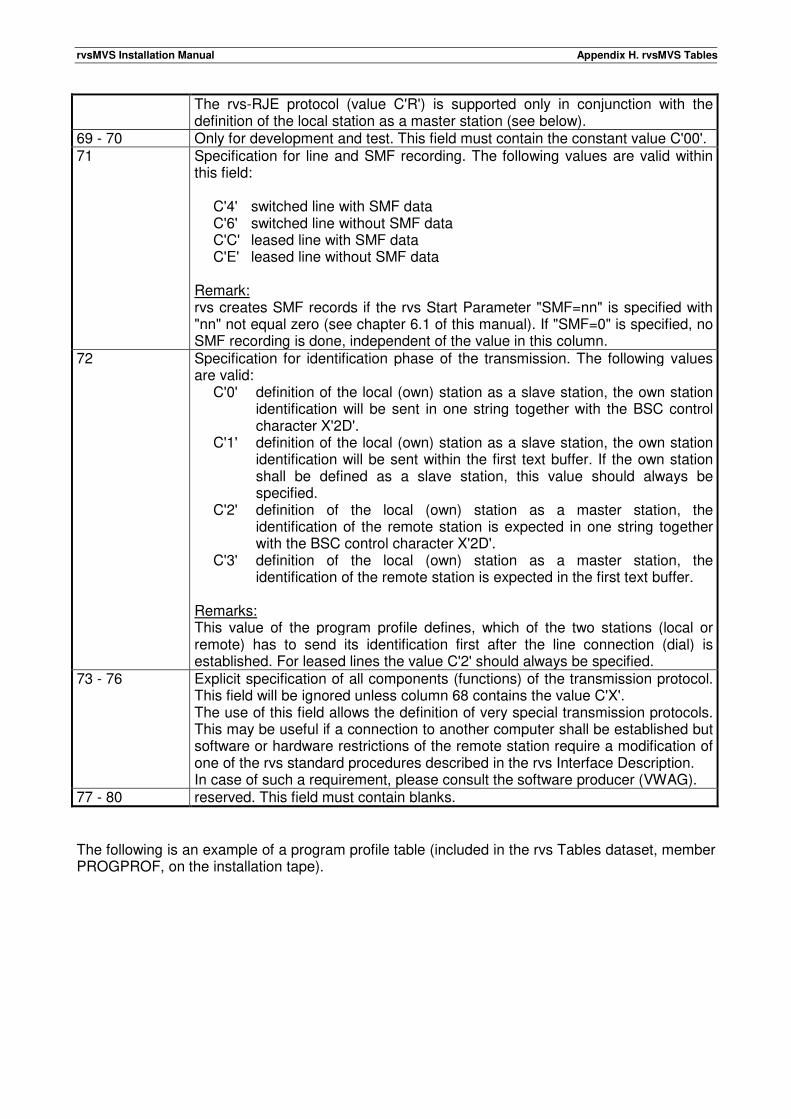
rvsMVS Installation Manual Appendix H. rvsMVS Tables
The rvs-RJE protocol (value C'R') is supported only in conjunction with the definition of the local station as a master station (see below).
69 - 70 Only for development and test. This field must contain the constant value C'00'. 71 Specification for line and SMF recording. The following values are valid within
this field: C'4' switched line with SMF data C'6' switched line without SMF data C'C' leased line with SMF data C'E' leased line without SMF data Remark: rvs creates SMF records if the rvs Start Parameter "SMF=nn" is specified with "nn" not equal zero (see chapter 6.1 of this manual). If "SMF=0" is specified, no SMF recording is done, independent of the value in this column.
72 Specification for identification phase of the transmission. The following values are valid: C'0' definition of the local (own) station as a slave station, the own station
identification will be sent in one string together with the BSC control character X'2D'.
C'1' definition of the local (own) station as a slave station, the own station identification will be sent within the first text buffer. If the own station shall be defined as a slave station, this value should always be specified.
C'2' definition of the local (own) station as a master station, the identification of the remote station is expected in one string together with the BSC control character X'2D'.
C'3' definition of the local (own) station as a master station, the identification of the remote station is expected in the first text buffer.
Remarks: This value of the program profile defines, which of the two stations (local or remote) has to send its identification first after the line connection (dial) is established. For leased lines the value C'2' should always be specified.
73 - 76 Explicit specification of all components (functions) of the transmission protocol. This field will be ignored unless column 68 contains the value C'X'. The use of this field allows the definition of very special transmission protocols. This may be useful if a connection to another computer shall be established but software or hardware restrictions of the remote station require a modification of one of the rvs standard procedures described in the rvs Interface Description. In case of such a requirement, please consult the software producer (VWAG).
77 - 80 reserved. This field must contain blanks.
The following is an example of a program profile table (included in the rvs Tables dataset, member PROGPROF, on the installation tape).
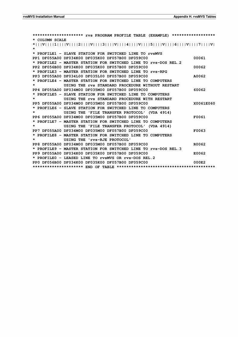
rvsMVS Installation Manual Appendix H. rvsMVS Tables
********************* rvs PROGRAM PROFILE TABLE (EXAMPLE) ******************
* COLUMN SCALE
*|||V||||1||||V||||2||||V||||3||||V||||4||||V||||5||||V||||6||||V||||7||||V|
*
* PROFILE1 - SLAVE STATION FOR SWITCHED LINE TO rvsMVS
PP1 DF055A00 DF034K00 DF035K00 DF057B00 DF059C00 00061
* PROFILE2 - MASTER STATION FOR SWITCHED LINE TO rvs-DOS REL.2
PP2 DF056B00 DF034K00 DF035K00 DF057B00 DF059C00 00062
* PROFILE3 - MASTER STATION FOR SWITCHED LINE TO rvs-RPG
PP3 DF055A00 DF034L00 DF035L00 DF057B00 DF059C00 A0062
* PROFILE4 - MASTER STATION FOR SWITCHED LINE TO COMPUTERS
* USING THE rvs STANDARD PROCEDURE WITHOUT RESTART
PP4 DF055A00 DF034M00 DF035M00 DF057B00 DF059C00 60062
* PROFILE5 - SLAVE STATION FOR SWITCHED LINE TO COMPUTERS
* USING THE rvs STANDARD PROCEDURE WITH RESTART
PP5 DF055A00 DF034M00 DF035M00 DF057B00 DF059C00 X0061E060
* PROFILE6 - SLAVE STATION FOR SWITCHED LINE TO COMPUTERS
* USING THE 'FILE TRANSFER PROTOCOL' (VDA 4914)
PP6 DF055A00 DF034M00 DF035M00 DF057B00 DF059C00 F0061
* PROFILE7 - MASTER STATION FOR SWITCHED LINE TO COMPUTERS
* USING THE 'FILE TRANSFER PROTOCOL' (VDA 4914)
PP7 DF055A00 DF034M00 DF035M00 DF057B00 DF059C00 F0063
* PROFILE8 - MASTER STATION FOR SWITCHED LINE TO COMPUTERS
* USING THE 'rvs-RJE PROTOCOL'
PP8 DF055A00 DF034M00 DF035M00 DF057B00 DF059C00 R0062
* PROFILE9 - MASTER STATION FOR SWITCHED LINE TO rvs-DOS REL.3
PP9 DF055A00 DF034K00 DF035K00 DF057B00 DF059C00 E0062
* PROFILE0 - LEASED LINE TO rvsMVS OR rvs-DOS REL.2
PP0 DF056B00 DF034K00 DF035K00 DF057B00 DF059C00 000E2
********************* END OF TABLE *****************************************
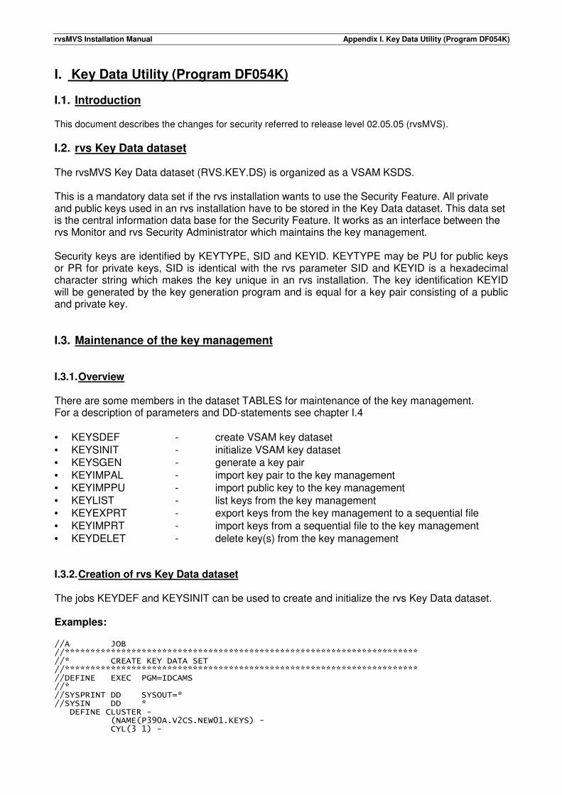
rvsMVS Installation Manual Appendix I. Key Data Utility (Program DF054K)
I. Key Data Utility (Program DF054K) I.1. Introduction This document describes the changes for security referred to release level 02.05.05 (rvsMVS).
I.2. rvs Key Data dataset The rvsMVS Key Data dataset (RVS.KEY.DS) is organized as a VSAM KSDS. This is a mandatory data set if the rvs installation wants to use the Security Feature. All private and public keys used in an rvs installation have to be stored in the Key Data dataset. This data set is the central information data base for the Security Feature. It works as an interface between the rvs Monitor and rvs Security Administrator which maintains the key management. Security keys are identified by KEYTYPE, SID and KEYID. KEYTYPE may be PU for public keys or PR for private keys, SID is identical with the rvs parameter SID and KEYID is a hexadecimal character string which makes the key unique in an rvs installation. The key identification KEYID will be generated by the key generation program and is equal for a key pair consisting of a public and private key. I.3. Maintenance of the key management I.3.1. Overview There are some members in the dataset TABLES for maintenance of the key management. For a description of parameters and DD-statements see chapter I.4 • KEYSDEF - create VSAM key dataset • KEYSINIT - initialize VSAM key dataset • KEYSGEN - generate a key pair • KEYIMPAL - import key pair to the key management • KEYIMPPU - import public key to the key management • KEYLIST - list keys from the key management • KEYEXPRT - export keys from the key management to a sequential file • KEYIMPRT - import keys from a sequential file to the key management • KEYDELET - delete key(s) from the key management I.3.2. Creation of rvs Key Data dataset The jobs KEYDEF and KEYSINIT can be used to create and initialize the rvs Key Data dataset. Examples: //A JOB //********************************************************************* //* CREATE KEY DATA SET //********************************************************************* //DEFINE EXEC PGM=IDCAMS //* //SYSPRINT DD SYSOUT=* //SYSIN DD * DEFINE CLUSTER - (NAME(P390A.V2CS.NEW01.KEYS) - CYL(3 1) -
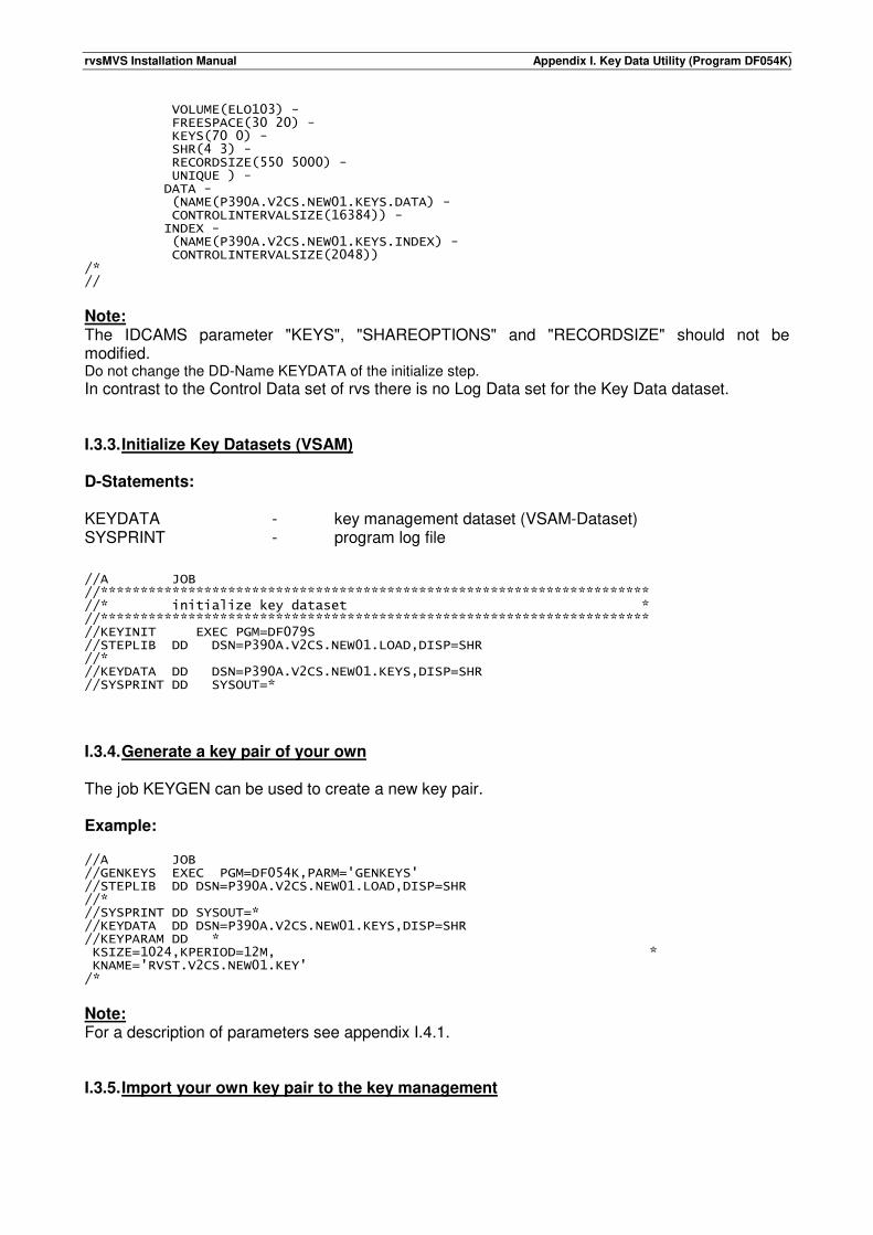
rvsMVS Installation Manual Appendix I. Key Data Utility (Program DF054K)
VOLUME(ELO103) - FREESPACE(30 20) - KEYS(70 0) - SHR(4 3) - RECORDSIZE(550 5000) - UNIQUE ) - DATA - (NAME(P390A.V2CS.NEW01.KEYS.DATA) - CONTROLINTERVALSIZE(16384)) - INDEX - (NAME(P390A.V2CS.NEW01.KEYS.INDEX) - CONTROLINTERVALSIZE(2048)) /* //
Note: The IDCAMS parameter "KEYS", "SHAREOPTIONS" and "RECORDSIZE" should not be modified. Do not change the DD-Name KEYDATA of the initialize step.
In contrast to the Control Data set of rvs there is no Log Data set for the Key Data dataset. I.3.3. Initialize Key Datasets (VSAM) D-Statements: KEYDATA - key management dataset (VSAM-Dataset) SYSPRINT - program log file //A JOB //********************************************************************* //* initialize key dataset * //********************************************************************* //KEYINIT EXEC PGM=DF079S //STEPLIB DD DSN=P390A.V2CS.NEW01.LOAD,DISP=SHR //* //KEYDATA DD DSN=P390A.V2CS.NEW01.KEYS,DISP=SHR //SYSPRINT DD SYSOUT=*
I.3.4. Generate a key pair of your own The job KEYGEN can be used to create a new key pair. Example: //A JOB //GENKEYS EXEC PGM=DF054K,PARM='GENKEYS' //STEPLIB DD DSN=P390A.V2CS.NEW01.LOAD,DISP=SHR //* //SYSPRINT DD SYSOUT=* //KEYDATA DD DSN=P390A.V2CS.NEW01.KEYS,DISP=SHR //KEYPARAM DD * KSIZE=1024,KPERIOD=12M, * KNAME='RVST.V2CS.NEW01.KEY' /*
Note: For a description of parameters see appendix I.4.1. I.3.5. Import your own key pair to the key management
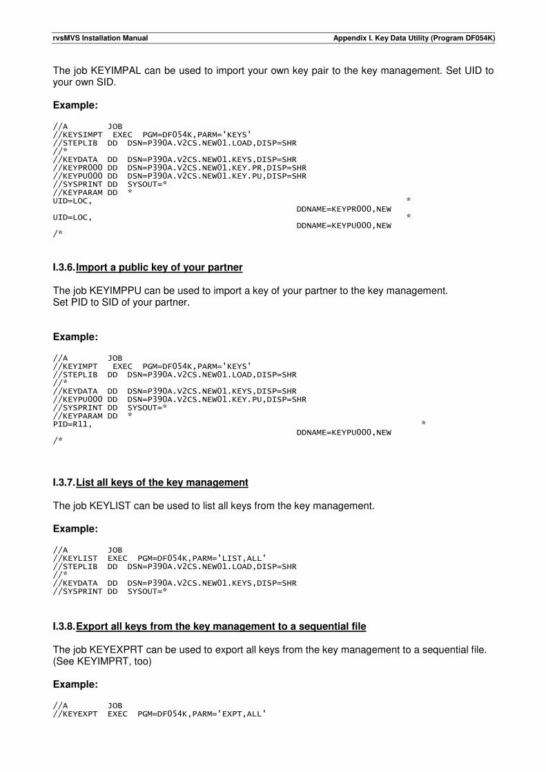
rvsMVS Installation Manual Appendix I. Key Data Utility (Program DF054K)
The job KEYIMPAL can be used to import your own key pair to the key management. Set UID to your own SID. Example: //A JOB //KEYSIMPT EXEC PGM=DF054K,PARM='KEYS' //STEPLIB DD DSN=P390A.V2CS.NEW01.LOAD,DISP=SHR //* //KEYDATA DD DSN=P390A.V2CS.NEW01.KEYS,DISP=SHR //KEYPR000 DD DSN=P390A.V2CS.NEW01.KEY.PR,DISP=SHR //KEYPU000 DD DSN=P390A.V2CS.NEW01.KEY.PU,DISP=SHR //SYSPRINT DD SYSOUT=* //KEYPARAM DD * UID=LOC, * DDNAME=KEYPR000,NEW UID=LOC, * DDNAME=KEYPU000,NEW /*
I.3.6. Import a public key of your partner The job KEYIMPPU can be used to import a key of your partner to the key management. Set PID to SID of your partner. Example: //A JOB //KEYIMPT EXEC PGM=DF054K,PARM='KEYS' //STEPLIB DD DSN=P390A.V2CS.NEW01.LOAD,DISP=SHR //* //KEYDATA DD DSN=P390A.V2CS.NEW01.KEYS,DISP=SHR //KEYPU000 DD DSN=P390A.V2CS.NEW01.KEY.PU,DISP=SHR //SYSPRINT DD SYSOUT=* //KEYPARAM DD * PID=R11, * DDNAME=KEYPU000,NEW /*
I.3.7. List all keys of the key management The job KEYLIST can be used to list all keys from the key management. Example: //A JOB //KEYLIST EXEC PGM=DF054K,PARM='LIST,ALL' //STEPLIB DD DSN=P390A.V2CS.NEW01.LOAD,DISP=SHR //* //KEYDATA DD DSN=P390A.V2CS.NEW01.KEYS,DISP=SHR //SYSPRINT DD SYSOUT=*
I.3.8. Export all keys from the key management to a sequential file The job KEYEXPRT can be used to export all keys from the key management to a sequential file. (See KEYIMPRT, too) Example: //A JOB //KEYEXPT EXEC PGM=DF054K,PARM='EXPT,ALL'
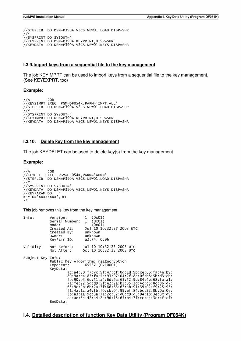
rvsMVS Installation Manual Appendix I. Key Data Utility (Program DF054K)
//STEPLIB DD DSN=P390A.V2CS.NEW01.LOAD,DISP=SHR //* //SYSPRINT DD SYSOUT=* //KEYPRINT DD DSN=P390A.KEYPRINT,DISP=SHR //KEYDATA DD DSN=P390A.V2CS.NEW01.KEYS,DISP=SHR
I.3.9. Import keys from a sequential file to the key management The job KEYIMPRT can be used to import keys from a sequential file to the key management. (See KEYEXPRT, too) Example: //A JOB //KEYSIMPT EXEC PGM=DF054K,PARM='IMPT,ALL' //STEPLIB DD DSN=P390A.V2CS.NEW01.LOAD,DISP=SHR //* //SYSPRINT DD SYSOUT=* //KEYIMPRT DD DSN=P390A.KEYPRINT,DISP=SHR //KEYDATA DD DSN=P390A.V2CS.NEW01.KEYS,DISP=SHR
I.3.10. Delete key from the key management The job KEYDELET can be used to delete key(s) from the key management. Example: //A JOB //KEYDEL EXEC PGM=DF054K,PARM='ADMN' //STEPLIB DD DSN=P390A.V2CS.NEW01.LOAD,DISP=SHR //* //SYSPRINT DD SYSOUT=* //KEYDATA DD DSN=P390A.V2CS.NEW01.KEYS,DISP=SHR //KEYPARAM DD * KEYID='XXXXXXXX',DEL /*
This job removes this key from the key management. Info: Version: 1 (0x01) Serial Number: 1 (0x01) Mode: 1 (0x01) Created At: Jul 10 10:32:27 2003 UTC Created By: unknown Owner: unknown KeyPair ID: a2:74:f0:96 Validity: Not Before: Jul 10 10:32:25 2003 UTC Not After: Oct 10 10:32:25 2003 UTC Subject Key Info: Public Key Algorithm: rsaEncryption Exponent: 65537 (0x10001) KeyData: ac:a4:30:f7:7c:9f:47:cf:0d:1d:9b:ce:66:fa:4e:b9: 80:9a:c4:83:fa:5e:93:97:04:2f:8c:0f:b8:5b:d3:cb: fb:90:b3:6d:51:a4:6d:6a:65:52:9d:84:4e:68:fa:a1: 7a:fe:22:5d:d9:5f:e2:2a:b3:35:3d:4c:c5:8c:86:d7: 65:9c:2b:6b:2a:7f:86:63:63:ab:91:39:02:f9:25:93: f1:4a:1c:a4:fb:f0:cb:04:99:ef:84:bc:22:0b:0a:0e: 2b:a3:1a:9c:3a:71:2c:52:d0:c9:d5:94:18:3e:3c:d9: ca:ae:34:42:a4:2e:9d:15:65:b4:7f:cc:e4:3c:cf:cf: EndData:
I.4. Detailed description of function Key Data Utility (Program DF054K)
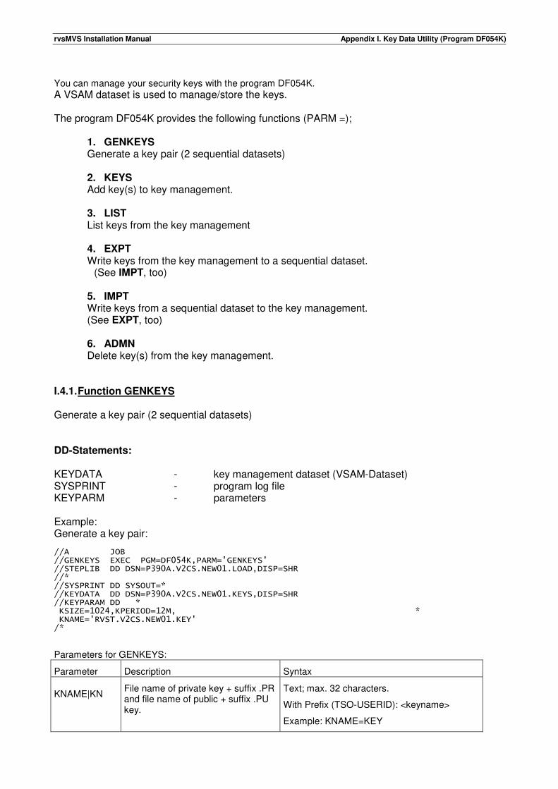
rvsMVS Installation Manual Appendix I. Key Data Utility (Program DF054K)
You can manage your security keys with the program DF054K.
A VSAM dataset is used to manage/store the keys. The program DF054K provides the following functions (PARM =);
1. GENKEYS Generate a key pair (2 sequential datasets)
2. KEYS Add key(s) to key management. 3. LIST List keys from the key management 4. EXPT Write keys from the key management to a sequential dataset. (See IMPT, too) 5. IMPT Write keys from a sequential dataset to the key management. (See EXPT, too) 6. ADMN Delete key(s) from the key management.
I.4.1. Function GENKEYS Generate a key pair (2 sequential datasets) DD-Statements: KEYDATA - key management dataset (VSAM-Dataset) SYSPRINT - program log file KEYPARM - parameters Example: Generate a key pair: //A JOB //GENKEYS EXEC PGM=DF054K,PARM='GENKEYS' //STEPLIB DD DSN=P390A.V2CS.NEW01.LOAD,DISP=SHR //* //SYSPRINT DD SYSOUT=* //KEYDATA DD DSN=P390A.V2CS.NEW01.KEYS,DISP=SHR //KEYPARAM DD * KSIZE=1024,KPERIOD=12M, * KNAME='RVST.V2CS.NEW01.KEY' /*
Parameters for GENKEYS:
Parameter Description Syntax
KNAME|KN File name of private key + suffix .PR and file name of public + suffix .PU key.
Text; max. 32 characters.
With Prefix (TSO-USERID): <keyname>
Example: KNAME=KEY
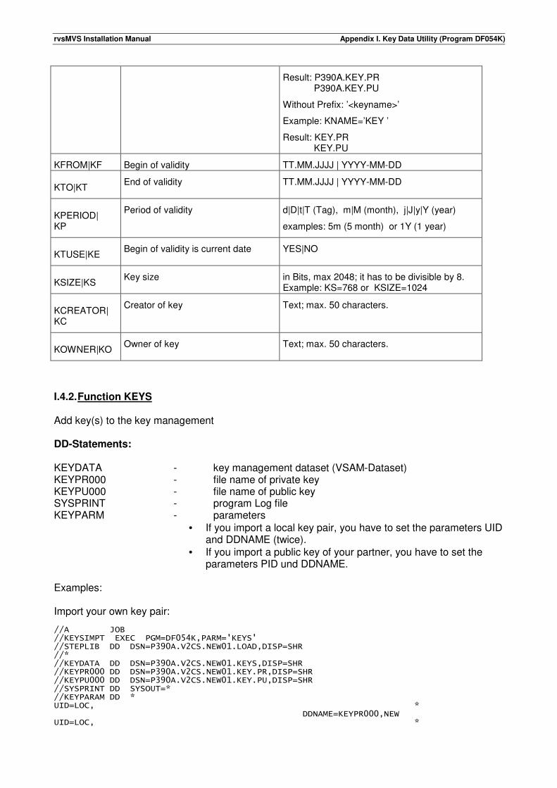
rvsMVS Installation Manual Appendix I. Key Data Utility (Program DF054K)
Result: P390A.KEY.PR P390A.KEY.PU
Without Prefix: ’<keyname>’
Example: KNAME=’KEY ’
Result: KEY.PR KEY.PU
KFROM|KF Begin of validity TT.MM.JJJJ | YYYY-MM-DD
KTO|KT End of validity TT.MM.JJJJ | YYYY-MM-DD
KPERIOD| KP
Period of validity d|D|t|T (Tag), m|M (month), j|J|y|Y (year)
examples: 5m (5 month) or 1Y (1 year)
KTUSE|KE Begin of validity is current date YES|NO
KSIZE|KS Key size in Bits, max 2048; it has to be divisible by 8.
Example: KS=768 or KSIZE=1024
KCREATOR| KC
Creator of key Text; max. 50 characters.
KOWNER|KO Owner of key Text; max. 50 characters.
I.4.2. Function KEYS Add key(s) to the key management DD-Statements: KEYDATA - key management dataset (VSAM-Dataset) KEYPR000 - file name of private key KEYPU000 - file name of public key SYSPRINT - program Log file KEYPARM - parameters
• If you import a local key pair, you have to set the parameters UID and DDNAME (twice).
• If you import a public key of your partner, you have to set the parameters PID und DDNAME.
Examples: Import your own key pair: //A JOB //KEYSIMPT EXEC PGM=DF054K,PARM='KEYS' //STEPLIB DD DSN=P390A.V2CS.NEW01.LOAD,DISP=SHR //* //KEYDATA DD DSN=P390A.V2CS.NEW01.KEYS,DISP=SHR //KEYPR000 DD DSN=P390A.V2CS.NEW01.KEY.PR,DISP=SHR //KEYPU000 DD DSN=P390A.V2CS.NEW01.KEY.PU,DISP=SHR //SYSPRINT DD SYSOUT=* //KEYPARAM DD * UID=LOC, * DDNAME=KEYPR000,NEW UID=LOC, *
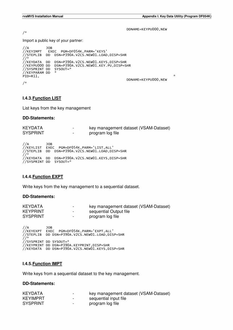
rvsMVS Installation Manual Appendix I. Key Data Utility (Program DF054K)
DDNAME=KEYPU000,NEW /*
Import a public key of your partner: //A JOB //KEYIMPT EXEC PGM=DF054K,PARM='KEYS' //STEPLIB DD DSN=P390A.V2CS.NEW01.LOAD,DISP=SHR //* //KEYDATA DD DSN=P390A.V2CS.NEW01.KEYS,DISP=SHR //KEYPU000 DD DSN=P390A.V2CS.NEW01.KEY.PU,DISP=SHR //SYSPRINT DD SYSOUT=* //KEYPARAM DD * PID=R11, * DDNAME=KEYPU000,NEW /*
I.4.3. Function LIST List keys from the key management DD-Statements: KEYDATA - key management dataset (VSAM-Dataset) SYSPRINT - program log file //A JOB //KEYLIST EXEC PGM=DF054K,PARM='LIST,ALL' //STEPLIB DD DSN=P390A.V2CS.NEW01.LOAD,DISP=SHR //* //KEYDATA DD DSN=P390A.V2CS.NEW01.KEYS,DISP=SHR //SYSPRINT DD SYSOUT=*
I.4.4. Function EXPT Write keys from the key management to a sequential dataset. DD-Statements: KEYDATA - key management dataset (VSAM-Dataset) KEYPRINT - sequential Output file SYSPRINT - program log file //A JOB //KEYEXPT EXEC PGM=DF054K,PARM='EXPT,ALL' //STEPLIB DD DSN=P390A.V2CS.NEW01.LOAD,DISP=SHR //* //SYSPRINT DD SYSOUT=* //KEYPRINT DD DSN=P390A.KEYPRINT,DISP=SHR //KEYDATA DD DSN=P390A.V2CS.NEW01.KEYS,DISP=SHR
I.4.5. Function IMPT Write keys from a sequential dataset to the key management. DD-Statements: KEYDATA - key management dataset (VSAM-Dataset) KEYIMPRT - sequential input file SYSPRINT - program log file
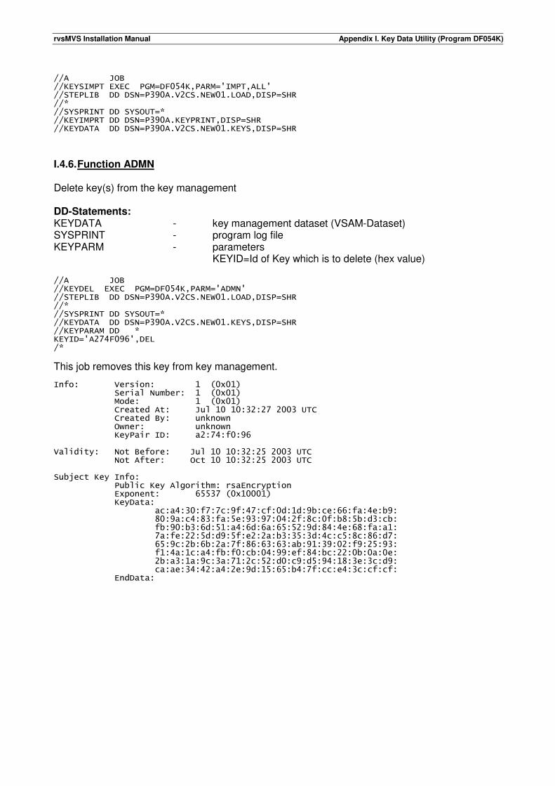
rvsMVS Installation Manual Appendix I. Key Data Utility (Program DF054K)
//A JOB //KEYSIMPT EXEC PGM=DF054K,PARM='IMPT,ALL' //STEPLIB DD DSN=P390A.V2CS.NEW01.LOAD,DISP=SHR //* //SYSPRINT DD SYSOUT=* //KEYIMPRT DD DSN=P390A.KEYPRINT,DISP=SHR //KEYDATA DD DSN=P390A.V2CS.NEW01.KEYS,DISP=SHR
I.4.6. Function ADMN Delete key(s) from the key management DD-Statements: KEYDATA - key management dataset (VSAM-Dataset) SYSPRINT - program log file KEYPARM - parameters KEYID=Id of Key which is to delete (hex value) //A JOB //KEYDEL EXEC PGM=DF054K,PARM='ADMN' //STEPLIB DD DSN=P390A.V2CS.NEW01.LOAD,DISP=SHR //* //SYSPRINT DD SYSOUT=* //KEYDATA DD DSN=P390A.V2CS.NEW01.KEYS,DISP=SHR //KEYPARAM DD * KEYID='A274F096',DEL /*
This job removes this key from key management. Info: Version: 1 (0x01) Serial Number: 1 (0x01) Mode: 1 (0x01) Created At: Jul 10 10:32:27 2003 UTC Created By: unknown Owner: unknown KeyPair ID: a2:74:f0:96 Validity: Not Before: Jul 10 10:32:25 2003 UTC Not After: Oct 10 10:32:25 2003 UTC Subject Key Info: Public Key Algorithm: rsaEncryption Exponent: 65537 (0x10001) KeyData: ac:a4:30:f7:7c:9f:47:cf:0d:1d:9b:ce:66:fa:4e:b9: 80:9a:c4:83:fa:5e:93:97:04:2f:8c:0f:b8:5b:d3:cb: fb:90:b3:6d:51:a4:6d:6a:65:52:9d:84:4e:68:fa:a1: 7a:fe:22:5d:d9:5f:e2:2a:b3:35:3d:4c:c5:8c:86:d7: 65:9c:2b:6b:2a:7f:86:63:63:ab:91:39:02:f9:25:93: f1:4a:1c:a4:fb:f0:cb:04:99:ef:84:bc:22:0b:0a:0e: 2b:a3:1a:9c:3a:71:2c:52:d0:c9:d5:94:18:3e:3c:d9: ca:ae:34:42:a4:2e:9d:15:65:b4:7f:cc:e4:3c:cf:cf: EndData:
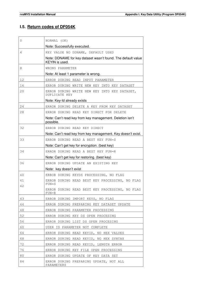
rvsMVS Installation Manual Appendix I. Key Data Utility (Program DF054K)
I.5. Return codes of DF054K
0 NORMAL (OK)
Note: Successfully executed.
4 KEY VALUE NO DDNAME, DEFAULT USED
Note: DDNAME for key dataset wasn’t found. The default value KEYIN is used.
8 WRONG PARAMETER
Note: At least 1 parameter is wrong.
12 ERROR DURING READ INPUT PARAMETER
16 ERROR DURING WRITE NEW KEY INTO KEY DATASET
20 ERROR DURING WRITE NEW KEY INTO KEY DATASET, DUPLICATE KEY
Note: Key-Id already exists
24 ERROR DURING DELETE A KEY FROM KEY DATASET
28 ERROR DURING READ KEY DIRECT FOR DELETE
Note: Can’t read key from key management. Deletion isn’t possible.
32 ERROR DURING READ KEY DIRECT
Note: Can’t read key from key management. Key doesn’t exist.
33 ERROR DURING READ A BEST KEY FUN=S
Note: Can’t get key for encryption. (best key)
34 ERROR DURING READ A BEST KEY FUN=R
Note: Can’t get key for restoring. (best key)
36 ERROR DURING UPDATE AN EXISTING KEY
Note: key doesn’t exist
40
41
42
ERROR DURING KEYDS PROCESSING, NO FLAG
ERROR DURING READ BEST KEY PROCESSING, NO FLAG FUN=S
ERROR DURING READ BEST KEY PROCESSING, NO FLAG FUN=R
43 ERROR DURING IMPORT KEYS, NO FLAG
44 ERROR DURING PREPARING KEY DATASET UPDATE
48 ERROR DURING PARAMETER PROCESSING
52 ERROR DURING KEY DS OPEN PROCESING
56 ERROR DURING LIST DS OPEN PROCESING
60 USER ID PARAMETER NOT COMPLETE
64 ERROR DURING READ KEYID, NO HEX VALUES
68 ERROR DURING READ KEYID, NO HEX SYNTAX
72 ERROR DURING READ KEYID, LENGTH ERROR
76 ERROR DURING KEY FILE OPEN PROCESSING
80 ERROR DURING UPDATE OF KEY DATA SET
84 ERROR DURING PREPARING UPDATE, NOT ALL PARAMETERS
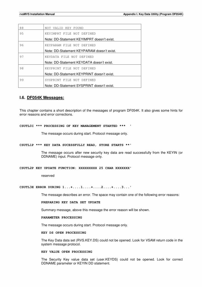
rvsMVS Installation Manual Appendix I. Key Data Utility (Program DF054K)
88 NOT VALID KEY FOUND
95 KEYIMPRT FILE NOT DEFINED
Note: DD-Statement KEYIMPRT doesn’t exist.
96 KEYPARAM FILE NOT DEFINED
Note: DD-Statement KEYPARAM doesn’t exist.
97 KEYDATA FILE NOT DEFINED
Note: DD-Statement KEYDATA doesn’t exist.
98 KEYPRINT FILE NOT DEFINED
Note: DD-Statement KEYPRINT doesn’t exist.
99 SYSPRINT FILE NOT DEFINED
Note: DD-Statement SYSPRINT doesn’t exist.
I.6. DF054K Messages: This chapter contains a short description of the messages of program DF054K. It also gives some hints for error reasons and error corrections.
CSUTL0I *** PROCESSING OF KEY MANAGEMENT STARTED *** '
The message occurs during start. Protocol message only.
CSUTL1P *** KEY DATA SUCESSFULLY READ, STORE STARTS **'
The message occurs after new security key data are read successfully from the KEYIN (or DDNAME) input. Protocol message only.
CSUTL2P KEY UPDATE FUNCTION: XXXXXXXXX 25 CHAR XXXXXXX'
reserved
CSUTL3E ERROR DURING 1...+....1....+....2....+....3...'
The message describes an error. The space may contain one of the following error reasons: PREPARING KEY DATA SET UPDATE
Summary message, above this message the error reason will be shown. PARAMETER PROCESSING
The message occurs during start. Protocol message only. KEY DS OPEN PROCESSING
The Key Data data set (RVS.KEY.DS) could not be opened. Look for VSAM return code in the system message protocol. KEY VALUE OPEN PROCESSING
The Security Key value data set (user.KEYDS) could not be opened. Look for correct DDNAME parameter or KEYIN DD statement.
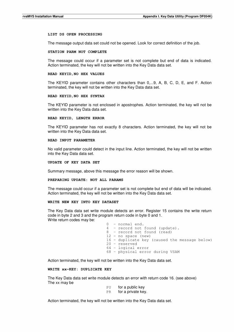
rvsMVS Installation Manual Appendix I. Key Data Utility (Program DF054K)
LIST DS OPEN PROCESSING
The message output data set could not be opened. Look for correct definition of the job. STATION PARM NOT COMPLETE
The message could occur if a parameter set is not complete but end of data is indicated. Action terminated, the key will not be written into the Key Data data set. READ KEYID,NO HEX VALUES
The KEYID parameter contains other characters than 0,...9, A, B, C, D, E, and F. Action terminated, the key will not be written into the Key Data data set. READ KEYID,NO HEX SYNTAX
The KEYID parameter is not enclosed in apostrophes. Action terminated, the key will not be written into the Key Data data set. READ KEYID, LENGTH ERROR
The KEYID parameter has not exactly 8 characters. Action terminated, the key will not be written into the Key Data data set. READ INPUT PARAMETER
No valid parameter could detect in the input line. Action terminated, the key will not be written into the Key Data data set. UPDATE OF KEY DATA SET
Summary message, above this message the error reason will be shown. PREPARING UPDATE: NOT ALL PARAMS
The message could occur if a parameter set is not complete but end of data will be indicated. Action terminated, the key will not be written into the Key Data data set. WRITE NEW KEY INTO KEY DATASET
The Key Data data set write module detects an error. Register 15 contains the write return code in byte 2 and 3 and the program return code in byte 0 and 1. Write return codes may be:
0 - normal end. 4 - record not found (update). 8 - record not found (read) 12 – no space (new) 16 – duplicate key (caused the message below) 20 - reserved 64 – logical error 68 – physical error during VSAM
Action terminated, the key will not be written into the Key Data data set. WRITE xx-KEY: DUPLICATE KEY
The Key Data data set write module detects an error with return code 16. (see above) The xx may be
PU for a public key PR for a private key.
Action terminated, the key will not be written into the Key Data data set.
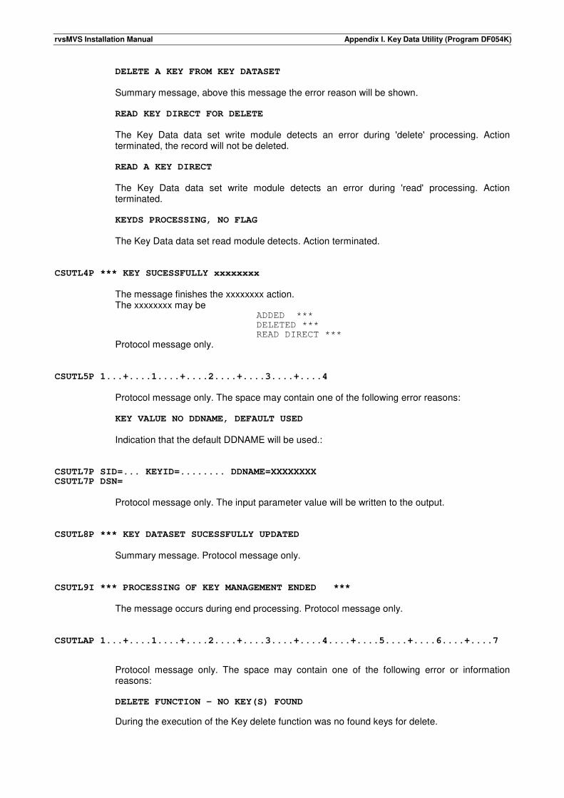
rvsMVS Installation Manual Appendix I. Key Data Utility (Program DF054K)
DELETE A KEY FROM KEY DATASET
Summary message, above this message the error reason will be shown. READ KEY DIRECT FOR DELETE
The Key Data data set write module detects an error during 'delete' processing. Action terminated, the record will not be deleted. READ A KEY DIRECT
The Key Data data set write module detects an error during 'read' processing. Action terminated. KEYDS PROCESSING, NO FLAG
The Key Data data set read module detects. Action terminated.
CSUTL4P *** KEY SUCESSFULLY xxxxxxxx
The message finishes the xxxxxxxx action. The xxxxxxxx may be
ADDED *** DELETED *** READ DIRECT ***
Protocol message only.
CSUTL5P 1...+....1....+....2....+....3....+....4 Protocol message only. The space may contain one of the following error reasons: KEY VALUE NO DDNAME, DEFAULT USED
Indication that the default DDNAME will be used.:
CSUTL7P SID=... KEYID=........ DDNAME=XXXXXXXX CSUTL7P DSN=
Protocol message only. The input parameter value will be written to the output.
CSUTL8P *** KEY DATASET SUCESSFULLY UPDATED Summary message. Protocol message only.
CSUTL9I *** PROCESSING OF KEY MANAGEMENT ENDED *** The message occurs during end processing. Protocol message only.
CSUTLAP 1...+....1....+....2....+....3....+....4....+....5....+....6....+....7
Protocol message only. The space may contain one of the following error or information reasons: DELETE FUNCTION - NO KEY(S) FOUND
During the execution of the Key delete function was no found keys for delete.
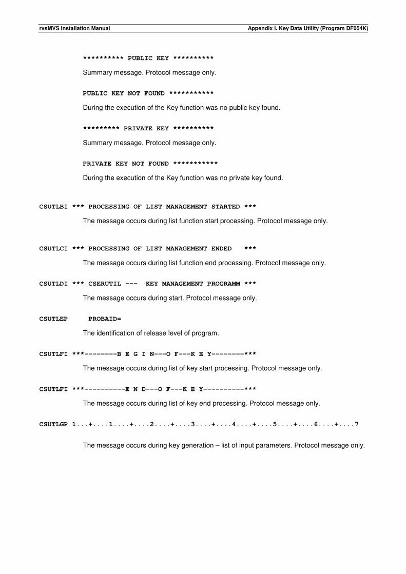
rvsMVS Installation Manual Appendix I. Key Data Utility (Program DF054K)
********** PUBLIC KEY **********
Summary message. Protocol message only. PUBLIC KEY NOT FOUND ***********
During the execution of the Key function was no public key found. ********* PRIVATE KEY **********
Summary message. Protocol message only. PRIVATE KEY NOT FOUND ***********
During the execution of the Key function was no private key found.
CSUTLBI *** PROCESSING OF LIST MANAGEMENT STARTED ***
The message occurs during list function start processing. Protocol message only. CSUTLCI *** PROCESSING OF LIST MANAGEMENT ENDED ***
The message occurs during list function end processing. Protocol message only. CSUTLDI *** CSERUTIL --- KEY MANAGEMENT PROGRAMM ***
The message occurs during start. Protocol message only. CSUTLEP PROBAID=
The identification of release level of program. CSUTLFI ***--------B E G I N---O F---K E Y--------***
The message occurs during list of key start processing. Protocol message only. CSUTLFI ***----------E N D---O F---K E Y----------***
The message occurs during list of key end processing. Protocol message only. CSUTLGP 1...+....1....+....2....+....3....+....4....+....5....+....6....+....7
The message occurs during key generation – list of input parameters. Protocol message only.
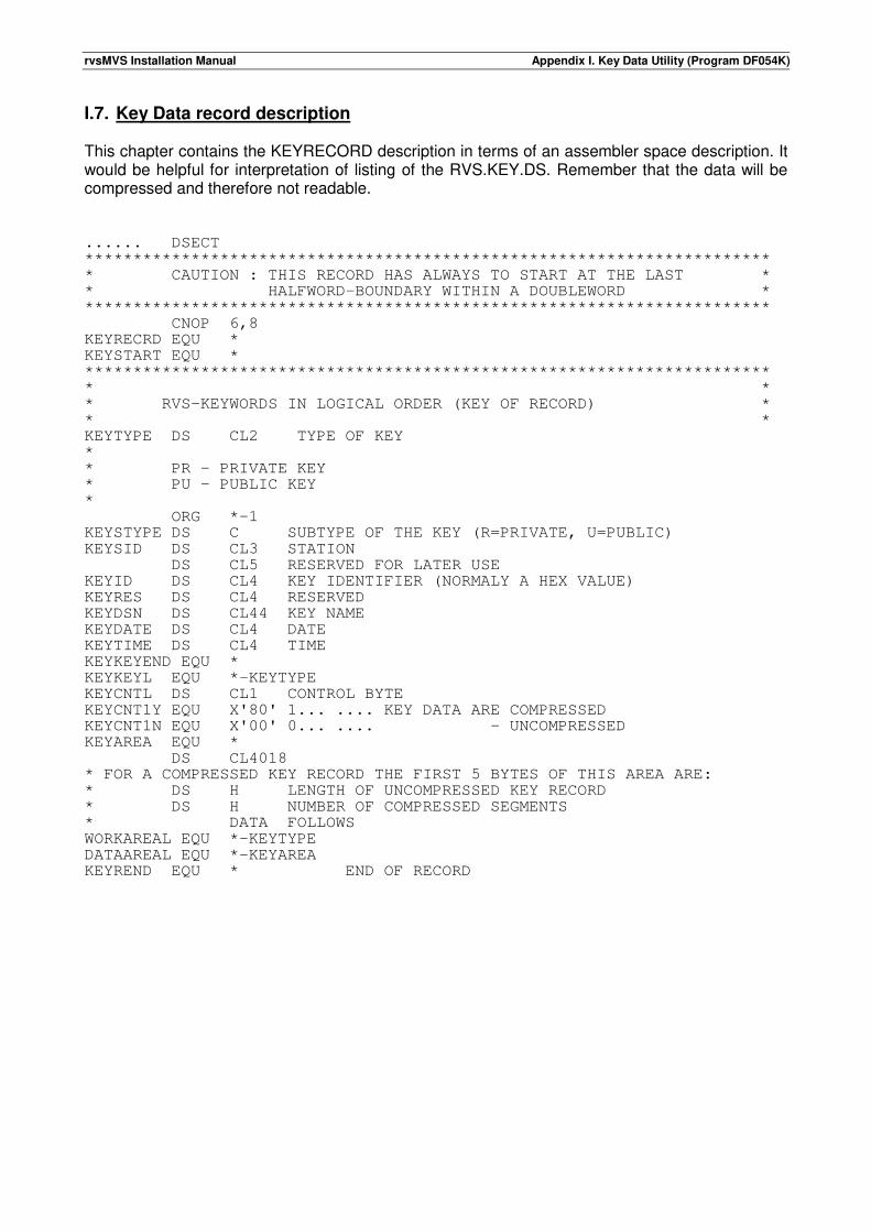
rvsMVS Installation Manual Appendix I. Key Data Utility (Program DF054K)
I.7. Key Data record description This chapter contains the KEYRECORD description in terms of an assembler space description. It would be helpful for interpretation of listing of the RVS.KEY.DS. Remember that the data will be compressed and therefore not readable. ...... DSECT *********************************************************************** * CAUTION : THIS RECORD HAS ALWAYS TO START AT THE LAST * * HALFWORD-BOUNDARY WITHIN A DOUBLEWORD * *********************************************************************** CNOP 6,8 KEYRECRD EQU * KEYSTART EQU * *********************************************************************** * * * RVS-KEYWORDS IN LOGICAL ORDER (KEY OF RECORD) * * * KEYTYPE DS CL2 TYPE OF KEY * * PR - PRIVATE KEY * PU - PUBLIC KEY * ORG *-1 KEYSTYPE DS C SUBTYPE OF THE KEY (R=PRIVATE, U=PUBLIC) KEYSID DS CL3 STATION DS CL5 RESERVED FOR LATER USE KEYID DS CL4 KEY IDENTIFIER (NORMALY A HEX VALUE) KEYRES DS CL4 RESERVED KEYDSN DS CL44 KEY NAME KEYDATE DS CL4 DATE KEYTIME DS CL4 TIME KEYKEYEND EQU * KEYKEYL EQU *-KEYTYPE KEYCNTL DS CL1 CONTROL BYTE KEYCNT1Y EQU X'80' 1... .... KEY DATA ARE COMPRESSED KEYCNT1N EQU X'00' 0... .... - UNCOMPRESSED KEYAREA EQU * DS CL4018 * FOR A COMPRESSED KEY RECORD THE FIRST 5 BYTES OF THIS AREA ARE: * DS H LENGTH OF UNCOMPRESSED KEY RECORD * DS H NUMBER OF COMPRESSED SEGMENTS * DATA FOLLOWS WORKAREAL EQU *-KEYTYPE DATAAREAL EQU *-KEYAREA KEYREND EQU * END OF RECORD

rvsMVS Installation Manual Appendix I. Key Data Utility (Program DF054K)
This page will be intentionally empty.
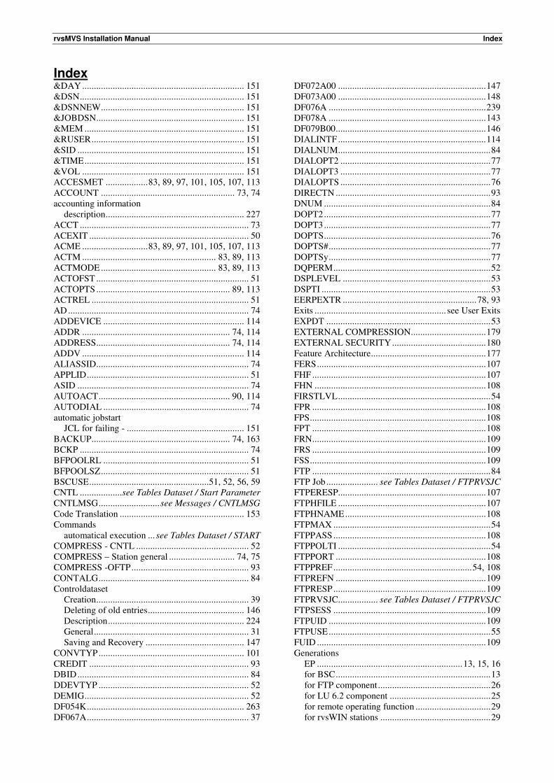
rvsMVS Installation Manual Index
Index &DAY ..................................................................... 151
&DSN ...................................................................... 151
&DSNNEW ............................................................. 151
&JOBDSN ............................................................... 151
&MEM .................................................................... 151
&RUSER ................................................................. 151
&SID ....................................................................... 151
&TIME .................................................................... 151
&VOL ..................................................................... 151
ACCESMET .................. 83, 89, 97, 101, 105, 107, 113
ACCOUNT ......................................................... 73, 74
accounting information
description ........................................................... 227
ACCT ........................................................................ 73
ACEXIT .................................................................... 50
ACME ............................ 83, 89, 97, 101, 105, 107, 113
ACTM ......................................................... 83, 89, 113
ACTMODE ................................................. 83, 89, 113
ACTOFST ................................................................. 51
ACTOPTS ......................................................... 89, 113
ACTREL ................................................................... 51
AD ............................................................................. 74
ADDEVICE ............................................................ 114
ADDR ............................................................... 74, 114
ADDRESS ......................................................... 74, 114
ADDV ..................................................................... 114
ALIASSID ................................................................. 74
APPLID ..................................................................... 51
ASID ......................................................................... 74
AUTOACT ........................................................ 90, 114
AUTODIAL .............................................................. 74
automatic jobstart
JCL for failing - .................................................. 151
BACKUP ........................................................... 74, 163
BCKP ........................................................................ 74
BFPOOLRL .............................................................. 51
BFPOOLSZ ............................................................... 51
BSCUSE ...................................................51, 52, 56, 59
CNTL .................. see Tables Dataset / Start Parameter
CNTLMSG .......................... see Messages / CNTLMSG
Code Translation ..................................................... 153
Commands
automatical execution ... see Tables Dataset / START
COMPRESS - CNTL ................................................ 52
COMPRESS – Station general ............................ 74, 75
COMPRESS -OFTP .................................................. 93
CONTALG ................................................................ 84
Controldataset
Creation ................................................................. 39
Deleting of old entries ......................................... 146
Description .......................................................... 224
General .................................................................. 31
Saving and Recovery .......................................... 147
CONVTYP .............................................................. 101
CREDIT .................................................................... 93
DBID ......................................................................... 84
DDEVTYP ................................................................ 52
DEMIG ...................................................................... 52
DF054K ................................................................... 263
DF067A ..................................................................... 37
DF072A00 ............................................................... 147
DF073A00 ............................................................... 148
DF076A ................................................................... 239
DF078A ................................................................... 143
DF079B00 ................................................................ 146
DIALINTF ............................................................... 114
DIALNUM................................................................. 84
DIALOPT2 ................................................................ 77
DIALOPT3 ................................................................ 77
DIALOPTS ................................................................ 76
DIRECTN .................................................................. 93
DNUM ....................................................................... 84
DOPT2 ....................................................................... 77
DOPT3 ....................................................................... 77
DOPTS ....................................................................... 76
DOPTS# ..................................................................... 77
DOPTSy ..................................................................... 77
DQPERM ................................................................... 52
DSPLEVEL ............................................................... 53
DSPTI ........................................................................ 53
EERPEXTR ......................................................... 78, 93
Exits ........................................................ see User Exits
EXPDT ...................................................................... 53
EXTERNAL COMPRESSION ................................ 179
EXTERNAL SECURITY ........................................ 180
Feature Architecture ................................................. 177
FERS ........................................................................ 107
FHF .......................................................................... 107
FHN ......................................................................... 108
FIRSTLVL ................................................................. 54
FPR .......................................................................... 108
FPS ........................................................................... 108
FPT .......................................................................... 108
FRN .......................................................................... 109
FRS .......................................................................... 109
FSS ........................................................................... 109
FTP ............................................................................ 84
FTP Job ...................... see Tables Dataset / FTPRVSJC
FTPERESP............................................................... 107
FTPHFILE ............................................................... 107
FTPHNAME ............................................................ 108
FTPMAX ................................................................... 54
FTPPASS ................................................................. 108
FTPPOLTI ................................................................. 54
FTPPORT ................................................................ 108
FTPPREF ........................................................... 54, 108
FTPREFN ................................................................ 109
FTPRESP ................................................................. 109
FTPRVSJC................. see Tables Dataset / FTPRVSJC
FTPSESS ................................................................. 109
FTPUID ................................................................... 109
FTPUSE ..................................................................... 55
FUID ........................................................................ 109
Generations
EP .............................................................. 13, 15, 16
for BSC .................................................................. 13
for FTP component ................................................ 26
for LU 6.2 component ........................................... 25
for remote operating function ................................ 29
for rvsWIN stations ............................................... 29
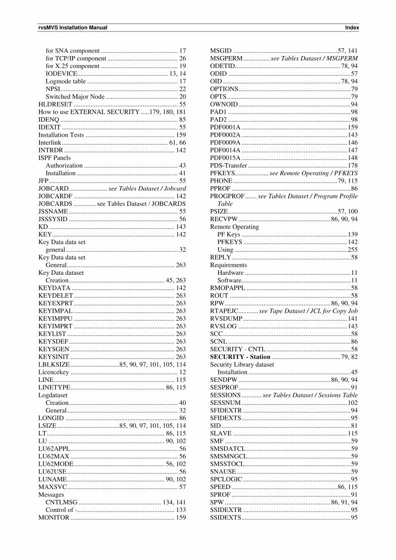
rvsMVS Installation Manual Index
for SNA component .............................................. 17
for TCP/IP component .......................................... 26
for X.25 component .............................................. 19
IODEVICE ...................................................... 13, 14
Logmode table ...................................................... 17
NPSI ...................................................................... 22
Switched Major Node ........................................... 20
HLDRESET .............................................................. 55
How to use EXTERNAL SECURITY .....179, 180, 181
IDENQ ...................................................................... 85
IDEXIT ..................................................................... 55
Installation Tests ..................................................... 159
Interlink ............................................................... 61, 66
INTRDR .................................................................. 142
ISPF Panels
Authorization ........................................................ 43
Installation ............................................................ 41
JFP ............................................................................. 55
JOBCARD ....................... see Tables Dataset / Jobcard
JOBCARDF ............................................................ 142
JOBCARDS ............. see Tables Dataset / JOBCARDS
JSSNAME ................................................................. 55
JSSSYSID ................................................................. 56
KD ........................................................................... 143
KEY......................................................................... 142
Key Data data set
general ................................................................... 32
Key Data data set
General ................................................................ 263
Key Data dataset
Creation ......................................................... 45, 263
KEYDATA ............................................................. 142
KEYDELET ............................................................ 263
KEYEXPRT ............................................................ 263
KEYIMPAL ............................................................ 263
KEYIMPPU ............................................................ 263
KEYIMPRT ............................................................ 263
KEYLIST ................................................................ 263
KEYSDEF ............................................................... 263
KEYSGEN .............................................................. 263
KEYSINIT .............................................................. 263
LBLKSIZE ............................. 85, 90, 97, 101, 105, 114
Licencekey ................................................................ 12
LINE ........................................................................ 115
LINETYPE ........................................................ 86, 115
Logdataset
Creation ................................................................. 40
General .................................................................. 32
LONGID ................................................................... 86
LSIZE ..................................... 85, 90, 97, 101, 105, 114
LT ...................................................................... 86, 115
LU ..................................................................... 90, 102
LU62APPL ................................................................ 56
LU62MAX ................................................................ 56
LU62MODE ...................................................... 56, 102
LU62USE .................................................................. 56
LUNAME .......................................................... 90, 102
MAXSVC .................................................................. 57
Messages
CNTLMSG ................................................. 134, 141
Control of -.......................................................... 133
MONITOR .............................................................. 159
MSGID .............................................................. 57, 141
MSGPERM ................ see Tables Dataset / MSGPERM
ODETID............................................................... 78, 94
ODID ......................................................................... 57
OID ...................................................................... 78, 94
OPTIONS................................................................... 79
OPTS .......................................................................... 79
OWNOID ................................................................... 94
PAD1 ......................................................................... 98
PAD2 ......................................................................... 98
PDF0001A ............................................................... 159
PDF0002A ............................................................... 143
PDF0009A ............................................................... 146
PDF0014A ............................................................... 147
PDF0015A ............................................................... 148
PDS-Transfer ........................................................... 178
PFKEYS.................... see Remote Operating / PFKEYS
PHONE .............................................................. 79, 115
PPROF ....................................................................... 86
PROGPROF ....... see Tables Dataset / Program Profile
Table
PSIZE ................................................................. 57, 100
RECVPW ....................................................... 86, 90, 94
Remote Operating
PF Keys ............................................................... 139
PFKEYS .............................................................. 142
Using ................................................................... 255
REPLY ....................................................................... 58
Requirements
Hardware ............................................................... 11
Software ................................................................. 11
RMOPAPPL .............................................................. 58
ROUT ........................................................................ 58
RPW ............................................................... 86, 90, 94
RTAPEJC............ see Tape Dataset / JCL for Copy Job
RVSDUMP .............................................................. 141
RVSLOG ................................................................. 143
SCC ............................................................................ 58
SCNL ......................................................................... 86
SECURITY - CNTL .................................................. 58
SECURITY - Station ......................................... 79, 82
Security Library dataset
Installation ............................................................. 45
SENDPW ....................................................... 86, 90, 94
SESPROF................................................................... 91
SESSIONS ............ see Tables Dataset / Sessions Table
SESSNUM ............................................................... 102
SFIDEXTR ................................................................ 94
SFIDEXTS ................................................................. 95
SID ............................................................................. 81
SLAVE .................................................................... 115
SMF ........................................................................... 59
SMSDATCL .............................................................. 59
SMSMNGCL ............................................................. 59
SMSSTOCL ............................................................... 59
SNAUSE .................................................................... 59
SPCLOGIC ................................................................ 95
SPEED ............................................................... 86, 115
SPROF ....................................................................... 91
SPW ............................................................... 86, 91, 94
SSIDEXTR ................................................................ 95
SSIDEXTS ................................................................. 95
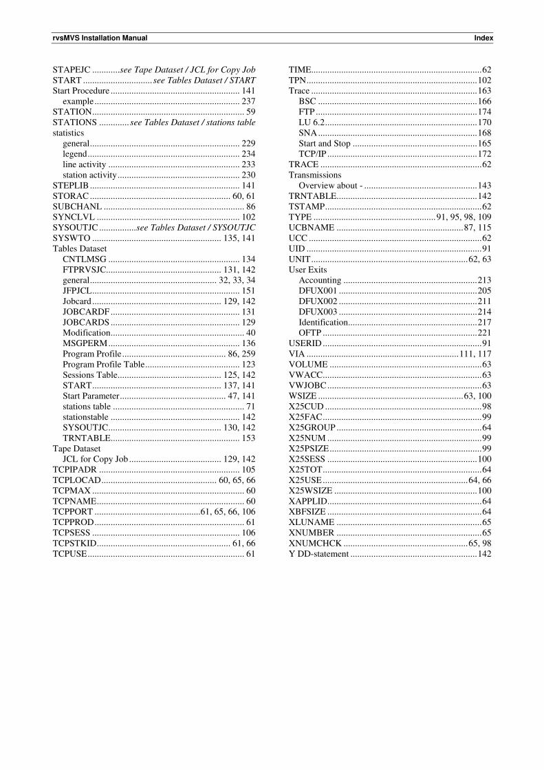
rvsMVS Installation Manual Index
STAPEJC ............ see Tape Dataset / JCL for Copy Job
START .............................. see Tables Dataset / START
Start Procedure ........................................................ 141
example ............................................................... 237
STATION .................................................................. 59
STATIONS ............. see Tables Dataset / stations table
statistics
general ................................................................. 229
legend .................................................................. 234
line activity ......................................................... 233
station activity ..................................................... 230
STEPLIB ................................................................. 141
STORAC ............................................................. 60, 61
SUBCHANL ............................................................. 86
SYNCLVL .............................................................. 102
SYSOUTJC ................ see Tables Dataset / SYSOUTJC
SYSWTO ........................................................ 135, 141
Tables Dataset
CNTLMSG ......................................................... 134
FTPRVSJC.................................................. 131, 142
general ....................................................... 32, 33, 34
JFPJCL ................................................................ 151
Jobcard ........................................................ 129, 142
JOBCARDF ........................................................ 131
JOBCARDS ........................................................ 129
Modification .......................................................... 40
MSGPERM ......................................................... 136
Program Profile ............................................. 86, 259
Program Profile Table ......................................... 123
Sessions Table ............................................. 125, 142
START ........................................................ 137, 141
Start Parameter .............................................. 47, 141
stations table ......................................................... 71
stationstable ........................................................ 142
SYSOUTJC ................................................. 130, 142
TRNTABLE ........................................................ 153
Tape Dataset
JCL for Copy Job ........................................ 129, 142
TCPIPADR ............................................................. 105
TCPLOCAD .................................................. 60, 65, 66
TCPMAX .................................................................. 60
TCPNAME ................................................................ 60
TCPPORT ..............................................61, 65, 66, 106
TCPPROD ................................................................. 61
TCPSESS ................................................................ 106
TCPSTKID .......................................................... 61, 66
TCPUSE .................................................................... 61
TIME .......................................................................... 62
TPN .......................................................................... 102
Trace ........................................................................ 163
BSC ..................................................................... 166
FTP ...................................................................... 174
LU 6.2 .................................................................. 170
SNA ..................................................................... 168
Start and Stop ...................................................... 165
TCP/IP ................................................................. 172
TRACE ...................................................................... 62
Transmissions
Overview about - ................................................. 143
TRNTABLE ............................................................. 142
TSTAMP .................................................................... 62
TYPE ..................................................... 91, 95, 98, 109
UCBNAME ....................................................... 87, 115
UCC ........................................................................... 62
UID ............................................................................ 91
UNIT .................................................................... 62, 63
User Exits
Accounting .......................................................... 213
DFUX001 ............................................................ 205
DFUX002 ............................................................ 211
DFUX003 ............................................................ 214
Identification........................................................ 217
OFTP ................................................................... 221
USERID ..................................................................... 91
VIA .................................................................. 111, 117
VOLUME .................................................................. 63
VWACC..................................................................... 63
VWJOBC ................................................................... 63
WSIZE ............................................................... 63, 100
X25CUD .................................................................... 98
X25FAC ..................................................................... 99
X25GROUP ............................................................... 64
X25NUM ................................................................... 99
X25PSIZE .................................................................. 99
X25SESS ................................................................. 100
X25TOT ..................................................................... 64
X25USE ............................................................... 64, 66
X25WSIZE .............................................................. 100
XAPPLID................................................................... 64
XBFSIZE ................................................................... 64
XLUNAME ............................................................... 65
XNUMBER ............................................................... 65
XNUMCHCK ...................................................... 65, 98
Y DD-statement ....................................................... 142