Embed Size (px)
Citation preview

Product No.: Multiple
Book No.: 1271057-02 V6
Installation Manual
Self-cleaning Hermetic Separators
A MRPX 614HGV-14CC MRPX 614HGV-74CH MRPX 614HGV-74CW MRPX 614HGV-74C
A MRPX 714HGV-14CB MRPX 714HGV-14CC MRPX 714HGV-74CH MRPX 714 HGV-74CW MRPX 714HGV-74CB BRPX 714HGV-34CD MRPX 714HGV-34C
C MRPX 518HGV-74CH MRPX 518HGV-74CW MRPX 518HGV-74C
B MRPX 618HGV-14CC MRPX 618HGV-74CF MRPX 618HGV-74CH MRPX 618HGV-74CW MRPX 618HGV-74CB BRPX 618HGV-34CD MRPX 618HGV-34C
H MRPX 718HGV-74CW MRPX 718HGV-74CC MRPX 718HGV-74C
H MRPX 818HGV-74C
B MRPX 818HGV-14CB BRPX 818HGV-34CH MRPX 818HGV-74CW MRPX 818HGV-74C
Product No.:
881208-01-01881208-01-01881208-01-01881208-01-01
881208-02-01881208-02-01881208-02-01881208-02-01881208-02-01881208-02-01881208-02-01
881209-01-01881209-01-01881209-01-01
881209-02-01881209-02-01881209-02-01881209-02-01881209-02-01881209-02-01881209-02-01
881209-03-01881209-03-01881209-03-01
881210-01-01
881210-01-02881210-01-02881210-01-02881210-01-02

Alfa Laval Separation ABSeparator Manuals, dept. SKELS-147 80 Tumba, Sweden
Telephone: +46 8 53 06 50 00Telefax: +46 8 53 03 10 40
Printed in Sweden, 00-05
© Alfa Laval Separation AB 2000
This publication or any part thereof may not be reproduced or transmitted by any process or means without prior written permission of Alfa Laval Separation AB.

als and observe the ation, operation, ce.
ctions can result in
clear only foreseeable conditions ings are given, therefore, for
ended usage of the machine and its
Study instruction manuwarnings before installservice and maintenan
Not following the instruserious accidents.
In order to make the informationhave been considered. No warnsituations arising from the uninttools.
3

4

Contents
1 Safety Instructions 7
2 Technical reference 13
2.1 Identification and safety signs on the machine 15
2.2 Technical data 19
2.3 Motor drive data (CT-motors) 34
2.4 Motor drive data (standard motor)BM / BB / HM / WM / RPX 818 44
2.5 Foundations 46
2.6 Lifting instructions 48
2.7 Foundation drawing 50
2.8 Basic size drawings 54
2.9 Connection list, all separators except BM / BB / HM / WM / RPX 818 82
2.10 Connection list,BM / BB / HM / WM / RPX 818 86
2.11 Interconnection diagram 90
3 Interface description 91
3.1 Interface description, standard motor, frequency drive 92
3.2 Interface description, CT-motor 100
4 Demand specification 109
4.1 Service water 110
4.2 Compressed air 111
5

5 Installation and first start 113
5.1 Preparations 114
5.2 Before first start 115
5.3 First start 116
5.4 Operation 116
5.5 Stopping 118
5.6 Selection of outlet impeller (twin phase separators) 119
6

1 Safety Instructions
G00
1041
1
The centrifugal separator includes parts that rotate at high speed. This means that:
• Kinetic energy is high
• Great forces are generated
• Stopping time is long
Manufacturing tolerances are extremely fine. Rotating parts are carefully balanced to reduce undesired vibrations that can cause a breakdown. Material properties have been considered carefully during design to withstand stress and fatigue.
The separator is designed and supplied for a specific separation duty (type of liquid, rotational speed, temperature, density etc.) and must not be used for any other purpose.
Incorrect operation and maintenance can result in unbalance due to build-up of sediment, reduction of material strength, etc., that subsequently could lead to serious damage and/or injury.
The following basic safety instructions therefore apply:
• Use the separator only for the purpose and parameter range specified by Alfa Laval.
• Strictly follow the instructions for installation, operation and maintenance.
• Ensure that personnel are competent and have sufficient knowledge of maintenance and operation, especially concerning emergency stopping procedures.
• Use only Alfa Laval genuine spare parts and the special tools supplied.
7

1 Safety Instructions
S00
513
11S
005
5611
DANGER
Disintegration hazards
• Use the separator only for the purpose and parameter range specified by Alfa Laval.
• If excessive vibration occurs, stop separator and keep bowl filled with liquid during rundown.
• When power cables are connected, always check direction of motor rotation. If incorrect, vital rotating parts could unscrew.
• Check that the gear ratio is correct for power frequency used. If incorrect, subsequent overspeed may result in a serious break down.
• Welding or heating of parts that rotate can seriously affect material strength.
• Wear on the large lock ring thread must not exceed safety limit. φ-mark on lock ring must not pass opposite φ-mark by more than specified distance.
• Inspect regularly for corrosion and erosion damage. Inspect frequently if process liquid is corrosive or erosive.
8

1 Safety Instructions
S0
0511
11S
0051
011
S0
0517
11S
005
1611
DANGER
Entrapment hazards
• Make sure that rotating parts have come to a complete standstill before starting any dismantling work.
• To avoid accidental start, switch off and lock power supply before starting any dismantling work.
• Assemble the machine completely before start. All covers and guards must be in place.
Electrical hazards
• Follow local regulations for electrical installation and earthing (grounding).
WARNING
Crush hazards
• Use correct lifting tools and follow lifting instructions.
• Do not work under a hanging load.
Noise hazards
• Use ear protection in noisy environments.
9

1 Safety Instructions
S00
554
11S
005
431
1
CAUTION
Burn hazards
• Lubrication oil and various machine surfaces can be hot and cause burns.
Cut hazards
• Sharp edges on separator discs and lock ring threads can cause cuts.
10

1 Safety Instructions
Warning signs in the text
Pay attention to the safety instructions in this manual. Below are definitions of the three grades of warning signs used in the text where there is a risk for injury to personnel.
DANGER
Type of hazard
This type of safety instruction indicates a situation which, if not avoided, could result in fatal injury or fatal damage to health.
WARNING
Type of hazard
This type of safety instruction indicates a situation which, if not avoided, could result in disabling injury or disabling damage to health.
CAUTION
Type of hazard
This type of safety instruction indicates a situation which, if not avoided, could result in light injury or light damage to health.
NOTE
This type of instruction indicates a situation which, if not avoided, could result in damage to the equipment.
11

1 Safety Instructions
12

2 Technical reference
Contents
2.1 Identification and safety signs on the machine 15
2.2 Technical data 19
2.2.1 A / C / H / W / MRPX 614HGV-14 / 74C 19
2.2.2 AM / BB / BM / CM / DM / HM / WM / RPX 714HGV-14 / 74C 21
2.2.3 C / H / W / MRPX 518HGV-74C 23
2.2.4 BB / BM / CM / DM / FM / HM / WM / RPX 618HGV-14 / 34 /74C 25
2.2.5 H / W / C MRPX 718HGV-74C 28
2.2.6 HMRPX 818HGV-74C 30
2.2.7 BM / BB / HM / WM / RPX 818 HGV-14 / 34 / 74C 32
2.3 Motor drive data (CT-motors) 34
2.3.1 A / C / H / W / MRPX 614 34
2.3.2 AM / BB / BM / CM / DM / HM / WM / RPX 714 36
2.3.3 C / H / W / MRPX 518 38
2.3.4 BB / BM / CM / DM / FM / HM / HWM / WM / RPX 618 40
2.3.5 DMRPX 618 42
2.4 Motor drive data (standard motor)BM / BB / HM / WM / RPX 818 44
2.5 Foundations 46
2.6 Lifting instructions 48
2.6.1 Separator 48
2.6.2 Bowl 49
2.6.3 Other parts 49
13

2 Technical reference
2.7 Foundation drawing 50
2.7.1 PX 614 / 714 50
2.7.2 PX 518 / 618 / 718 / 818 52
2.8 Basic size drawings 54
2.8.1 A / B / MRPX 614 / 714 54
2.8.2 C / H / W / MRPX 614 / 714 58
2.8.3 BBRPX / DMRPX 714 62
2.8.4 C / H / W / MRPX 518 / 618 64
2.8.5 B / F / MRPX 618,BMRPX 818 68
2.8.6 BBRPX 618, 818 / DMRPX 618 72
2.8.7 H / W / C MRPX 718H / W / MRPX 818 74
2.8.8 BBRPX 818, high flow 78
2.9 Connection list, all separators except BM / BB / HM / WM / RPX 818 82
2.10 Connection list,BM / BB / HM / WM / RPX 818 86
2.11 Interconnection diagram 90
14

2 Technical reference Identification and safety signs on the machine
example):
GV-14C
G06
637
51S
006
1411
2.1 Identification and safety signs on the machine
1. Machine plate Text on plate (
Separator A MRPX 614H
Manufacturing serial No / Year XXXX
Product No 881208-01-01
Machine top part 552032-02
Outlet 562013-02
Bowl 546860-12
Machine bottom part 553136-41
Max. speed (bowl) 4265 r/min
Direction of rotation (bowl) ←
Speed motor shaft 1500 r/min
El. current frequency 50 Hz
Recommended motor power 18,5 kW
Max. density of feed 1100 kg/m3
Max. density of sediment 1380 kg/m3
Max. density of operating liquid 1000 kg/m3
Process temperature min./max. 0 - 100 °C
15

Identification and safety signs on the machine 2 Technical reference
S00
615
21S
006
3211
S00
6311
1S
014
3221
Power supply frequency H MRPX 818
3. Safety label
Text on label:
DANGER
Read the instruction manuals before installation, operation and maintenance. Consider inspection intervals.
Failure to strictly follow instructions can lead to fatal injury.
If excessive vibration occurs, stop separator and keep bowl filled with liquid during rundown.
Out of balance vibration will become worse if bowl is not full.
Separator must stop rotating before any dismantling work is started.
4. Name plate
5. Arrow
Indicating direction of rotation.
7. Power supply frequency, all separators except HM/BM/BB/WM/ RPX 818
Power supply frequency,HMRPX 818 (spec. 881210-01-01)
16

2 Technical reference Identification and safety signs on the machine
S01
4572
1
Power supply frequency HM/BM/BB/WM/RPX 818
Power supply frequency,HM/BM/BB/WM/ RPX 818 (spec. 881210-01-02)
* Space reserved for plate indicating representative
DANGER
Disintegration hazard
This machine must not be operated with higher bowl speed than 4607 r/min.
17

Identification and safety signs on the machine 2 Technical reference
18

2 Technical reference 2.2 Technical data
anhydrous milk fat, CMRPX cold hot milk, WMRPX whey).
The Council Directive of the European Communities (CE-marking is possible if manuals are included in the delivery.
Safety of machines. Use of the machine in applications subject to hygienic demands requires a well adapted cleaning program.
EMC and amendments related to said directive.
r/min 50 Hz / 60 Hzr/min 50 Hz / 60 Hz50 Hz60 Hzkgm² 50 / 60 Hz
m³/hm³/hlitreslitresminute
litreslitres
°C°C min./max.kg/m3
kg/m3
kWkW (idling / at max. capacity)
minutes (min./max.)minutes (min./max.)minutes (average)
minutes
2.2 Technical data
2.2.1 A / C / H / W / MRPX 614HGV-14 / 74C
Alfa Laval ref. 562172, rev. 0 / 562170, rev. 3 (spec. 881208-01-01)
Application Dairy (AMRPXmilk, HMRPX
Designed in accordance with standards
89/392 EEC91/368 EEC93/44 EEC
EN 292-2
89/336
Bowl speed, synchronousMotor speed, synchronousGear ratio
Jp reduced to motor shaft
4266 / 42501500 / 180091:3285:36209,2 / 144,2
Hydraulic capacity (A MRPX)Hydraulic capacityMin./max. discharge volumeRecommended discharge volumeMin. discharge intervalRecommended discharge volume in cleaning cyclesBowl liquid volume
25 30 5 / 306 - 81
14-1630
Ambient temperatureFeed temperatureMax. density of feed / sedimentMax. density of operating liquid
+ 5 to + 450 to + 1001100 / 13801000
Motor powerPower consumption
18,56 / 13
Start timeStopping time with brakeStopping time without brakeMax running time without flow, bowl empty / filled
10 / 1216 / 1845
60 / 80
19

2.2 Technical data 2 Technical reference
Bel(A)dB(A)mm/s (new sep./sep. in use)
mm/s
litreskgkg (without motor)kgmm
2
ontact with process fluid except for
gated in each case by the
set of complementary documents
Sound powerSound pressure levelVibration level max.Alarm levels for vibration monitor, connection 750, 1st / 2nd
8,8717,1 / 9
6 / 8
Lubricating oil volumeBowl weightWeight of separatorMotor weightMax. bowl inner diameter
12,55941390290507
Bowl body material AL 111 2377-0
There are no other materials than stainless steel in csealings and gaskets.
Bowl must be kept filled during stopping sequence.
Any risk for corrosion and erosion have to be investiapplication centre.
Only land based installations permitted.
Further restrictions and instructions are found in thewith the number 562169.
20

2 Technical reference 2.2 Technical data
anhydrous milk fat, BMRPX/fuge, CMRPX cold milk, DMRPX/ ilk, WMRPX whey).
The Council Directive of the European Communities (CE-marking is possible if manuals are included in the delivery.
Safety of machines. Use of the machine in applications subject to hygienic demands requires a well adapted cleaning program.
EMC and amendments related to said directive.
r/min 50 Hz / 60 Hzr/min 50 Hz / 60 Hz
r/min 50 Hz / 60 Hz50 Hz60 Hz
m³/h
m³/hlitres
litresminute
litres
°C°C min./max.kg/m3
kg/m3
kWkW (idling / at max. capacity)kgm² 50 / 60 Hz
minutes
minutes (min./max.)minutes (min./max.)minutes (average)
2.2.2 AM / BB / BM / CM / DM / HM / WM / RPX 714HGV-14 / 74C
Alfa Laval ref. 562177, rev. 1 / 562174, rev. 3 (spec. 881208-02-01)
Application Dairy (AMRPXBBRPX bactoHMRPX hot m
Designed in accordance with standards
89/392 EEC91/368 EEC93/44 EEC
EN 292-2
89/336 EEC
Bowl speed, synchronousMotor speed, synchronousRevolution counter speed, synchronousGear ratio
5069 / 51191500 / 1800
125 / 15098:2991:32
Hydraulic capacity (A/C/MRPX)Hydraulic capacity (BBRPX, B/D/H/W/MRPX Min./max. discharge volumeRecommended discharge volume during operationMin. discharge intervalRecommended discharge volume in cleaning cycles
30
40 5 / 25 *)
6 - 81
14 - 16
Ambient temperatureFeed temperatureMax. density of feed / sedimentMax. density of operating liquid
+ 5 to + 450 to + 1001100 / **)1000
Motor powerPower consumptionJp reduced to motor shaftMax running time without flow, bowl empty / filled
229 / 18295,4 / 209,2
60 / 80
Start timeStopping time with brakeStopping time without brake
16 / 1716 / 1845
21

2.2 Technical data 2 Technical reference
Bel(A)dB(A)mm/s (new sep./sep. in use)
mm/s
litreslitreskgkg (without motor)kgmm
2
ontact with process fluid except for
gated in each case by the
set of complementary documents
RPX: 2033 kg/m3
RPX: 1367 kg/m3
RPX: 1247 kg/m3
RPX, C MRPX, H MRPX, MRPX: 1380 kg/m3
Sound powerSound pressure levelVibration level max.Alarm levels for vibration monitor, connection 750, 1st / 2nd
8,7707,1 / 9
6 / 8
Lubricating oil volumeBowl liquid volumeBowl weightWeight of separatorMotor weightMax. bowl inner diameter
12,530595*1390290507
Bowl body material AL 111 2377-0
There are no other materials than stainless steel in csealings and gaskets.
Bowl must be kept filled during stopping sequence.
Any risk for corrosion and erosion have to be investiapplication centre.
Only land based installations permitted.
Further restrictions and instructions are found in thewith the number 562175.
*) A MRPX, C MRPX, H MRPX, W MRPX:Min./max. discharge volume 5 / 30 litresBowl weight 594 kg
**) B MB BD MA MW
22

2 Technical reference 2.2 Technical data
cold milk, HMRPX hot milk, ).
The Council Directive of the European Communities (CE-marking is possible if manuals are included in the delivery.
Safety of machines. Use of the machine in applications subject to hygienic demands requires a well adapted cleaning program.
EMC and amendments related to said directive.
r/min 50 Hz / 60 Hzr/min 50 Hz / 60 Hzr/min 50 Hz / 60 Hz50 Hz60 Hzkgm² 50 / 60 Hz
mmm³/hllitresminute
litres
°C°C min./max.kg/m3
kg/m3
kPa
kWkW (idling / at max. capacity)
minutes (min./max.)minutes (min./max.)minutes (average)
minutes
2.2.3 C / H / W / MRPX 518HGV-74C
Alfa Laval ref. 562184, rev. 1 / 562181, rev. 5 (spec. 881209-01-01)
Application Dairy (CMRPXWMRPX whey
Designed in accordance with standards
89/392 EEC91/368 EEC93/44 EEC
EN 292-2
89/336 EEC
Bowl speed, synchronousMotor speed, synchronousRevolution counter, synchronousGear ratio
Jp reduced to motor shaft
3955 / 39321500 / 1800125 / 15087:3383:38595,4 / 408,7
Max. bowl inner diameterHydraulic capacityMin./max. discharge volume during operationMin. discharge intervalMax. discharge volume during cleaning cycles
64430
10 / 181
35
Ambient temperatureFeed temperatureMax. density of feed / sedimentMax. density of operating liquidMax. pressure operating liquid
+ 5 to + 450 to + 1001100 / 1481100050
Motor powerPower consumption
2212 / 16
Start timeStopping time with brakeStopping time without brakeMax running time without flow, bowl empty / filled
14 / 1620 / 2380
60 / 60
23

2.2 Technical data 2 Technical reference
Bel(A)dB(A)mm/s (new sep./sep. in use)
mm/s
litreslitreslitreskgkg (without motor)kg
2
ontact with process fluid except for
gated in each case by the
set of complementary documents
Sound powerSound pressure levelVibration level max.Alarm levels for vibration monitor, connection 750, 1st / 2nd
9,2787,1 / 9
6 / 8
Lubricating oil volumeBowl liquid volumeSludge volume, efficient / totalBowl weightWeight of separatorMotor weight
12,56517 / 1711602080290
Bowl body material AL 111 2377-0
There are no other materials than stainless steel in csealings and gaskets.
Bowl must be kept filled during stopping sequence.
Any risk for corrosion and erosion have to be investiapplication centre.
Only land based installations permitted.
Further restrictions and instructions are found in thewith the number 562183.
24

2 Technical reference 2.2 Technical data
/BMRPX bactofuge, CMRPX cold desludger, FMRPX cream HMRPX hot milk, WMRPX whey).
The Council Directive of the European Communities (CE-marking is possible if manuals are included in the delivery.
Safety of machines. Use of the machine in applications subject to hygienic demands requires a well adapted cleaning program.
EMC and amendments related to said directive.
r/min 50 Hz / 60 Hzr/min 50 Hz / 60 Hzr/min 50 Hz / 60 Hz50 Hz60 Hz
m³/hm³/hm³/hm³/h
m³/hminute
°C°C min./max.kg/m3
kWkWkW (idling / at max. capacity)
minutes (min./max.)minutes (min./max.)minutes (average)
minutes
2.2.4 BB / BM / CM / DM / FM / HM / WM / RPX 618HGV-14 / 34 /74C
Alfa Laval ref. 562187, rev. 3 / 562185, rev. 4 (spec. 881209-02-01)
Application Dairy (BBRPXmilk, DMRPX concentration,
Designed in accordance with standards
89/392 EEC91/368 EEC93/44 EEC
EN 292-2
89/336 EEC
Bowl speed, synchronousMotor speed, synchronousRevolution counter, synchronousGear ratio
4266 / 42501500 / 1800125 / 15091:3285:36
Hydraulic capacity (F MRPX)Hydraulic capacity (H/W MRPX)Hydraulic capacity (B MRPX)Hydraulic capacity (C MRPX)Hydraulic capacity (BBRPX, DMRPX)Min. discharge interval
25 40 30 35
45 1
Ambient temperatureFeed temperatureMax. density of operating liquid
+ 5 to + 450 to + 1001000
Motor powerMotor power (D MRPX)Power consumption
253712 / 28
Start timeStopping time with brakeStopping time without brakeMax running time without flow, bowl empty / filled
15 / 1722/ 2580
60 / 60
25

2.2 Technical data 2 Technical reference
Bel(A)dB(A)mm/s (new sep./sep. in use)
mm/s
litres
kg (without motor)kg
2
litreslitres
litres
litreskg/m3
kgkgm² 50 / 60 Hz
litreslitres
litres
litreskg/m3
kgkgm² 50 / 60 Hz
litreslitres
litres
litreskg/m3
kgkgm² 50 / 60 Hz
Sound powerSound pressure levelVibration level max.Alarm levels for vibration monitor, connection 750, 1st / 2nd
9,2787,1 / 9
6 / 8
Lubricating oil volumeBowl weightWeight of separatorMotor weight
12,5See below2095290
Bowl body material AL 111 2377-0
H / W MRPX 618Bowl liquid volumeSludge volume, efficient / totalMin./max. discharge volume during operationMax. discharge volume in cleaning cyclesMax. density of feed / sedimentBowl weightJp reduced to motor shaft
7017 / 17
10 / 18
351100 / 14811120681,2 / 469,6
C MRPX 618Bowl liquid volumeSludge volume, efficient / totalMin./max. discharge volume during operationMax. discharge volume in cleaning cyclesMax. density of feed / sedimentBowl weightJp reduced to motor shaft
7717 / 17
10 / 18
351100 / 14811055661,8 / 456,2
B MRPX 618Bowl liquid volumeSludge volume, efficient / totalMin./max. discharge volume during operationMax. discharge volume in cleaning cyclesMax. density of feed / sedimentBowl weightJp reduced to motor shaft
63,51,75 / 17
10 / 18
351100 / 29151175699,0 / 481,9
26

2 Technical reference 2.2 Technical data
litreslitres
litres
litreskg/m3
kgkgm² 50 / 60 Hz
litreslitres
litres
litreskg/m3
kgkgm² 50 / 60 Hz
litreslitres
litres
litreskg/m3
kgkgm² 50 / 60 Hz
ontact with process fluid except for
igated in each case by the
set of complementary documents
F MRPX 618Bowl liquid volumeSludge volume, efficient / totalMin./max. discharge volume during operationMax. discharge volume in cleaning cyclesMax. density of feed / sedimentBowl weightJp reduced to motor shaft
701,8 / 17
10 / 18
351100 / 14811140681,2 / 469,6
B BRPX 618Bowl liquid volumeSludge volume, efficient / totalMin./max. discharge volume during operationMax. discharge volume in cleaning cyclesMax. density of feed / sedimentBowl weightJp reduced to motor shaft
6317 / 17
10 / 18
351100 / 14641175697,5 / 480,8
D MRPX 618Bowl liquid volumeSludge volume, efficient / totalMin./max. discharge volume during operationMax. discharge volume in cleaning cyclesMax. density of feed / sedimentBowl weightJp reduced to motor shaft
7236 / 136
10 / 18
351100 / 12791105661,8 / 456,2
There are no other materials than stainless steel in csealings and gaskets.
Bowl must be kept filled during stopping sequence.
Any risk for corrosion and erosion have to be investapplication centre.
Only land based installations permitted.
Further restrictions and instructions are found in thewith the number 562186.
27

2.2 Technical data 2 Technical reference
hot milk, WMRPX whey, CMRPX
The Council Directive of the European Communities (CE-marking is possible if manuals are included in the delivery.
Safety of machines. Use of the machine in applications subject to hygienic demands requires a well adapted cleaning program.
EMC and amendments related to said directive.
r/min 50 Hz / 60 Hzr/min 50 Hz / 60 Hz50 Hz60 Hz
m³/h
litresminutes
°C°C min./max.kg/m3
kg/m3
kWkW (idling / at max. capacity)
minutes (min./max.)minutes (min./max.)minutes (average)
minutes
Bel(A)dB(A)mm/s (new sep./sep. in use)
mm/s
kgm² (50Hz / 60Hz)kgm² (50Hz / 60Hz)
2.2.5 H / W / C MRPX 718HGV-74CAlfa Laval ref. 562190, rev. 2 / 562188, rev. 4 (spec. 881209-03-01)
Application Dairy (HMRPXcold milk).
Designed in accordance with standards
89/392 EEC91/368 EEC93/44 EEC
EN 292-2
89/336 EEC
Bowl speed, synchronousMotor speed, synchronousGear ratio
4266 / 42501500 / 180091:3285:36
Hydraulic capacityMin./max. discharge volume during operationMin./Max. discharge intervalMax. discharge volume in cleaning cycles
50
10 / 181 / 60
35
Ambient temperatureFeed temperatureMax. density of feed / sedimentMax. density of operating liquid
+ 5 to + 450 to + 1001100 / 14811000
Motor powerPower consumption
2515 / 28,5
Start timeStopping time with brakeStopping time without brakeMax. running time without flow, bowl empty / filled
20 / 2225 / 2880
60 / 60
Sound powerSound pressure levelVibration level max.Alarm levels for vibration monitor, connection 750, 1st / 2ndJp reduced to motor shaft:(HMRPX, WMRPX) (CMRPX)
9,2787,1 / 9
6 / 8
691,4 / 476,6661,8 / 456,2
28

2 Technical reference 2.2 Technical data
litres
kg kgkgkg
litreslitreslitresmm
2
ontact with process fluid except for
igated in each case by the
set of complementary documents
Lubricating oil volumeBowl weight:(HMRPX, WMRPX)(CMRPX)Weight of separatorMotor weightBowl liquid volume, (HMRPX, WMRPXBowl liquid volume, (CMRPX)Sludge volume, efficient / totalMax. bowl inner diameter
12,5
115510552075290
667717 / 17644
Bowl body material AL 111 2377-0
There are no other materials than stainless steel in csealings and gaskets.
Bowl must be kept filled during stopping sequence.
Any risk for corrosion and erosion have to be investapplication centre.
Only land based installations permitted.
Further restrictions and instructions are found in thewith the number 562189.
29

2.2 Technical data 2 Technical reference
hot milk).
The Council Directive of the European Communities (CE-marking is possible if manuals are included in the delivery.
Safety of machines. Use of the machine in applications subject to hygienic demands requires a well adapted cleaning program.
EMC and amendments related to said directive.
r/min 54 Hzr/min 54 Hzr/min 54 Hz54 Hzkgm²
m³/h
litresminute
litreslitreslitres
°C°C min./max.kg/m3
kg/m3
kPa
kWkW (idling / at max. capacity)
minutes (min./max.)minutes (min./max.)minutes (average)
minutes
Bel(A)dB(A)mm/s (new sep./sep. in use)
mm/s
2.2.6 HMRPX 818HGV-74CAlfa Laval ref. 564497, rev. 0 / 564499, rev. 2 (spec. 881210-01-01)
Application Dairy (HMRPX
Designed in accordance with standards
89/392 EEC91/368 EEC93/44 EEC
EN 292-2
89/336 EEC
Bowl speed, synchronousMotor speed, synchronousRevolution counter, synchronousGear ratioJp reduced to motor shaft
4607 162013591:32691
Hydraulic capacityMax. discharge volume during operationMin. discharge intervalMax. discharge volume in cleaning cyclesBowl liquid volumeSludge volume, efficient / total
65
17 1
356617 / 17
Ambient temperatureFeed temperatureMax. density of feed / sedimentMax. density of operating liquidMax. pressure operating liquid
+ 5 to + 450 to + 1001100 / 1481100050
Motor powerPower consumption
3715 / 28,5
Start timeStopping time with brakeStopping time without brakeMax. running time without flow, bowl empty / filled
12 / 1530 / 3580
60 / 60
Sound powerSound pressure levelVibration level max.Alarm levels for vibration monitor, connection 750, 1st / 2nd
9,3576,57,1 / 9
6 / 8
30

2 Technical reference 2.2 Technical data
litreskgkg (without motor)kgmm
2
ontact with process fluid except for
igated in each case by the
set of complementary documents
Lubricating oil volumeBowl weightWeight of separatorMotor weightMax. bowl inner diameter
12,511552075290644
Bowl body material AL 111 2397-0
There are no other materials than stainless steel in csealings and gaskets.
Bowl must be kept filled during stopping sequence.
Any risk for corrosion and erosion have to be investapplication centre.
Only land based installations permitted.
Further restrictions and instructions are found in thewith the number 564491.
31

2.2 Technical data 2 Technical reference
/ bactofuge, HMRPX hot milk, ).
Directive of the European Parliament and the Council relating to machinery, except for the instruction manuals (i.e. CE-marking is not possible).
Safety of machines. Use of the machine in applications subject to hygienic demands requires a well adapted cleaning program.
Acoustics - Determination of sound power levels of noice sources using sound pressure.
EMC and amendments related to said directive.
r/min 54 / 65 Hzr/min 54 / 65 Hz54 / 65 Hzkgm²
m³/h
m³/h
m³/hm³/h
minute
litres
°C°C min./max.kg/m3
kWkW (idling / at max. capacity)
minutes (min./max.)minutes (min./max.)minutes (average)
minutes
2.2.7 BM / BB / HM / WM / RPX 818 HGV-14 / 34 / 74C
Alfa Laval ref. 565387, rev. 1 / 565275, rev. 1 (spec. 881210-01-02)
Application Dairy (BBRPXWMRPX whey
Designed in accordance with standards
98/37 EC
EN 292-2
ISO 3744
89/336 EEC
Bowl speed, synchronousMotor speed, synchronousGear ratioJp reduced to motor shaft
4607 / 4604 1620 / 195091:32 / 85:36691
Hydraulic capacity, H/WMRPXHydraulic capacity, BBRPX (high flow)Hydraulic capacity, BBRPX (standard)Hydraulic capacity, BMRPXMax.discharge volume during operationMin. discharge intervalMax. discharge volume in cleaning cycles
65
60
4535
17 1
35
Ambient temperatureFeed temperatureMax. density of operating liquid
+ 5 to + 450 to + 1001000
Motor powerPower consumption
3715 / 28,5
Start timeStopping time with brakeStopping time without brakeMax. running time without flow, bowl empty / filled
12 / 1530 / 3080
60 / 60
32

2 Technical reference 2.2 Technical data
Bel(A)dB(A)mm/s (new sep./sep. in use)
mm/s
litreskg (without motor)kgmm
2
litreslitreskg/m3
kgkgm² 54 / 65 Hz
litreslitreskg/m3
kgkgm² 54 / 65 Hz
litreslitreskg/m3
kgkgm² 54 / 65 Hz
ontact with process fluid except for
igated in each case by the
set of complementary documents
Sound powerSound pressure levelVibration level max.Alarm levels for vibration monitor, connection 750, 1st / 2nd
9,3576,57,1 / 9
6 / 8
Lubricating oil volumeWeight of separatorMotor weightMax. bowl inner diameter
12,52075290644
Bowl body material AL 111 2398-0
B BRPX 818Bowl liquid volumeSludge volume, efficient / totalMax. density of feed / sedimentBowl weightJp reduced to motor shaft
6317 / 171100 / 14641175697,5 / 480,8
H / W / MRPX 818Bowl liquid volumeSludge volume, efficient / totalMax. density of feed / sedimentBowl weightJp reduced to motor shaft
6617 / 171100 / 14811155691,4 / 476,6
B MRPX 818Bowl liquid volumeSludge volume, efficient / totalMax. density of feed / sedimentBowl weightJp reduced to motor shaft
631,75 / 171100 / 29151175699,0 / 481,9
There are no other materials than stainless steel in csealings and gaskets.
Bowl must be kept filled during stopping sequence.
Any risk for corrosion and erosion have to be investapplication centre.
Only land based installations permitted.
Further restrictions and instructions are found in thewith the number 565376.
33

2.3 Motor drive data (CT-motors) 2 Technical reference
, outputasuredlculated
G06
9351
1
2.3 Motor drive data (CT-motors)
2.3.1 A / C / H / W / MRPX 614
Alfa Laval ref. 551106, rev. 4
A Speed, r/minB Current, amp.C Time, minutes
D ampE kW, inputF Motor speed
G kWH MeI Ca
34

2 Technical reference 2.3 Motor drive data (CT-motors)
Al.
higher.
r/min50 Hz
r/min60 Hz
η%
cos ϕ NmMs (Y)
1460 1760 88,8 0,89 110
2211), 155°.
Voltage
V
Rated current
A
Fuse
A
Cable, Cumin.mm2
Cable,minmm2
220 62 100 35 70
380 36 63 16 25
415 33 50 16 16
440 31 50 16 16
550 29 40 10 16
575 23 40 10 16
660 21 32 10 10
Motor data from Brook type test certificate 41366
Min. cable area: See also local codes
ηand cos ϕ valid for 50 Hz. Values for 60 Hz about 0,5%
Idling power output = 6 kW, input = 6,8 kW
Moment of inertia 25,87 kgm2 (bowl spindle)
Bowl speed max. 4265 r/min, motor 1500 or 1800 r/min
Tripping temperature 190°
MotorAL-no
kW Manufact Type No. of poles
540924 18,5 Brook UC 225 LHD
4
Tripping temperature for standard motor (AL-no 56
35

2.3 Motor drive data (CT-motors) 2 Technical reference
tputut
G06
9361
1
2.3.2 AM / BB / BM / CM / DM / HM / WM / RPX 714
Alfa Laval ref. 551105, rev. 3
A Speed, r/minB Current, amp.C Motor speed
D MeasuredE CalculatedF Time, minutes
G OuH Inp
36

2 Technical reference 2.3 Motor drive data (CT-motors)
Al.
higher.
r/min50 Hz
r/min60 Hz
η%
cos ϕ NmMs (Y)
1460 1760 88,9 0,88 110
2210), 155°.
Voltage
V
Rated current
A
Fuse
A
Cable, Cumin.mm2
Cable,minmm2
220 74 100 35 70
380 43 63 16 25
415 39 50 16 16
440 37 50 16 16
500 33 40 10 16
575 28 40 10 16
660 25 32 10 10
Motor data from Brook test certificate 41365
Min. cable area: See also local codes
ηand cos ϕ valid for 50 Hz. Values for 60 Hz about 0,5%
Idling power output = –, input = 10,2 kW
Moment of inertia 25,87 kgm2 (bowl spindle)
Bowl speed max. 5120 r/min, motor 1500 or 1800 r/min
Tripping temperature 190°
MotorAL-no
kW Manufact Type No. of poles
540924 22 Brook UC 225 LHD
4
Tripping temperature for standard motor (AL-no 56
37

2.3 Motor drive data (CT-motors) 2 Technical reference
H ampI kW (input)J kW (output)
G0
6937
11
2.3.3 C / H / W / MRPX 518Alfa Laval ref. 550624, rev. 3
A Speed, r/minB Current, amp.C Starting characteristics at
Y/∆-starting
D Motor speedE Time, minutesF MeasuredG Calculated
38

2 Technical reference 2.3 Motor drive data (CT-motors)
Al
at 380 V 50 Hz
z
)
r/min50 Hz
r/min60 Hz
η%
cos ϕ NmMs (Y)
1475 1770 91 0,86 174
2210), 155°.
Voltage
V
Rated current
A
Fuse
A
Cable, Cumin.mm2
Cable,min.mm2
220 73 125 50 70
380 42 80 25 35
415 38 80 25 35
440 37 80 25 35
500 32 63 16 25
575 28 63 16 25
660 24 50 10 16
NOTE
Recommended cable area is valid for a max. ambient temperature of 25 °C and with the cables freely installed.
Motor data acc. to Brooks type test certificate TT 42400
η and cos ϕ for 60 Hz. appr. of same values as for 50 H
Min. cable area: See also local codes
Idling power output = –, input = 12 kW
Moment of inertia 77,10 kgm2 (bowl spindle)
Bowl speed max. 3955 r/min (motor 1500 or 1800 r/min
Tripping temperature 190°
MotorAL-no
kW Manufact Type No. of poles
544143 22 Brook UC 225 LHD
4
Tripping temperature for standard motor (AL-no 56
39

2.3 Motor drive data (CT-motors) 2 Technical reference
G Time, minutesH OutputI Input
G0
693
811
2.3.4 BB / BM / CM / DM / FM / HM / HWM / WM / RPX 618
Alfa Laval ref. 550623, rev. 2
A CurrentB SpeedC Start characteristics
D Motor speedE MeasuredF Calculated
40

2 Technical reference 2.3 Motor drive data (CT-motors)
Al.
higher
)
r/min50 Hz
r/min60 Hz
η%
cos ϕ NmMs (Y)
1470 1760 92 0,86 210
2209), 155°.
Voltage
V
Rated current
A
Fuse
Amin
Cable, Cumin.mm2
Cable,minmm2
220 85 160 95 120
380 49 100 35 70
415 45 80 25 35
440 42 80 25 35
500 37 63 16 25
575 32 63 16 25
660 28 50 10 16
Motor data from Brooks type test certificate: T T42398
Min. cable area: See also local codes
η and cos ϕ valid for 50 Hz. Values for 60 Hz about 0,5%
Idling power: output = 12,2 kW, input = 14 kW
Moment of inertia 77,10 kgm2 (bowl spindle)
Bowl speed max. 4265 r/min (motor 1500 or 1800 r/min
Tripping temperature 190°
MotorAL-no
kW Manufact Type No. of poles
544143 25 Brook UC 225 LH
4
Tripping temperature for standard motor (AL-no 56
41

2.3 Motor drive data (CT-motors) 2 Technical reference
D InputE Output
G08
3754
1
2.3.5 DMRPX 618
Alfa Laval ref. 553577, rev. 0
A MeasuredB CalculatedC Motor speed
42

2 Technical reference 2.3 Motor drive data (CT-motors)
Al.
, 50 Hz
higher
)
r/min50 Hz
r/min60 Hz
η%
cos ϕ NmMs (Y)
1450 1750 91,5 0,87 210
62209 and 562650 37 kW), 155°.
Voltage
V
Rated current
A
Fuse
A
Cable, Cumin.mm2
Cable,minmm2
220 121 160 95 120
380 70 100 35 70
415 64 80 25 35
440 60 80 25 35
500 53 63 16 25
575 46 63 16 25
660 40 50 10 16
Motor data from Brooks test certificate: T T42397, 380 V
Min. cable area: See also local codes
η and cos ϕ valid for 50 Hz. Values for 60 Hz about 0,5%
Idling power: output = -, input = 12 kW
Moment of inertia 77,08 kgm2 (bowl spindle)
Bowl speed max. 4265 r/min (motor 1500 or 1800 r/min
Tripping temperature 190°
MotorAL-no
kW Manufact Type No. of poles
544143 37 Brook UC 225 LH
4
Tripping temperature for standard motors (AL-no 5
43
2.4 Motor drive data (standard motor) BM / BB / HM / WM / RPX 818 2 Technical reference
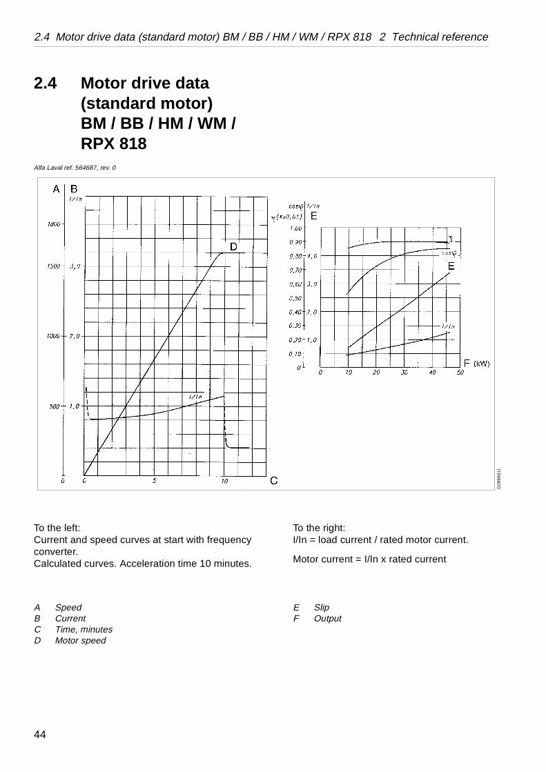
To the right:I/In = load current / rated motor current.
Motor current = I/In x rated current
E SlipF Output
G09
8461
1
2.4 Motor drive data (standard motor)BM / BB / HM / WM / RPX 818
Alfa Laval ref. 564687, rev. 0
To the left:Current and speed curves at start with frequency converter.Calculated curves. Acceleration time 10 minutes.
A SpeedB CurrentC Time, minutesD Motor speed
44

2 Technical reference 2.4 Motor drive data (standard motor) BM / BB / HM / WM / RPX 818
e s)
t. at 50 Hz
t)
1620 r/min
Speed54 Hz,r/min
Efficiency, η, %
Power factor, cos ϕ
Rated torque, Mn, Nm
1580 90,0 0,84 240
Cables and fuses (recommendations)
Note:The motor and the mains cables must be dimensioned acc. to local safety regulations.Shielded symmetrical motor cable is recommended.
Voltage Rated current
Cable size(copper) mm2
Fus(main
V A motor mains A
230 122 35 50 125
400 70 16 25 80
440 64 16 25 80
500 56 10 16 63
575 49 10 16 50
690 41 10 16 50
Performance curves acc. to Brook Hansen type test cer
Machine idling power consumption = 15 kW (motor inpu
Moment of inertia 85,45 kgm2 (bowl)
Bowl speed max. 4607 r/min. Motor synchronous speed
Tripping temperature 155°
MotorAL No.
Output, kW
Manu-facturer
Type No. of poles
562650 37 Brook Hansen
CF 200 M
4
45

2.5 Foundations 2 Technical reference
C0
0586
F1
1. Rubber cushion2. Frame foot3. Rectangular ring4. Washer5. Screw6. Holder7. Adjusting washer8. Foot on foundation plate9. Set screw
G0
6670
41
Level against the upper face of the holders (6)
2.5 Foundations
Specification
• The separator should be installed at floor level, see chapters ‘‘2.7 Foundation drawing” on page 50 for measures and how to pour the foundation plate in concrete.
• The separator must be installed on a strong and rigid foundation to reduce the influence of vibrations from adjacent machinery.
At delivery the parts 1-5 are fitted on the separator. The screw (5) is locked with Loctite 243 and tightened with 40 Nm.
Proceed in the following way when mounting the separator onto the feet of the foundation plate (8):
1. Level against the upper face of the three holders (6). Screw the holders to compensate for inclination, if any. Any gap between a holder and a foundation foot (8) must be eliminated by adding one or more adjusting washers (7).
NOTE
When lifting a separator it must always be hung securely. See chapter .
46

2 Technical reference 2.5 Foundations
2. Lower the separator into the three holders.
3. Tighten the set screws (9), first by hand (or by a hand tool, if necessary) until all of them are in contact with the frame feet (2).
Then tighten the set screws with 10 Nm.
4. Mount the bowl and check that the frame is horizontal by means of a level placed on the outer frame rim.
Make a new adjustment if necessary.
Further information can be found in chapter ‘‘2.8 Basic size drawings” on page 54.
NOTE
Tighten the set screws before mounting the bowl or cyclone.
47

2.6 Lifting instructions 2 Technical reference
G0
8369
31
2.6 Lifting instructions
2.6.1 SeparatorAlfa Laval ref. 557183, rev. 1 / 557187, rev. 1
Attach three endless slings or cables to the lifting eyes (the screws must be tightened with spanner).
Length of each sling must be min. 1,5 metres in circumference.
Do not lift the separator unless the inlet/outlet frame hood, cyclone, motor protecting cap and bowl have been removed.
NOTE
Machine weight without frame hood and bowl is approx. 1000 kg (PX 614, 714) and 1200 kg (PX 518, 618, 718, 818).
WARNING
Crush hazards
Use only the three special lifting eyes for lifting the machine, and follow lifting instructions. Do not work under hanging load.
A falling separator can cause accidents resulting in serious injury to persons and damage to equipment.
S0
1000
11
48

2 Technical reference 2.6 Lifting instructions
G06
671
21
2.6.2 Bowl
This instruction describes how to lift a complete bowl, which normally is done only during a transport of the separator.
When lifting the bowl, use the special lifting tool fastened on the bowl hood.
2.6.3 Other parts
The frame hood and the heavy bowl parts must be lifted by means of a hoist. Position the hoist exactly above the bowl centre. Use endless lifting straps and a lifting hook with safety catch.
Special tools from the tool kit must be used for dismantling and assembly. The special tools are specified in the Spare Parts Catalogue and are shown as illustrations together with the dismantling/assembly instructions.
NOTE
Check that the lock ring is properly tightened.
Weight to lift is approx. 600 kg (PX 614, 714) and 1100 kg (PX 518, 618, 718, 818).
When lifting the bowl out of the separator frame, the cap nut fixing the bowl to the bowl spindle and the screws fixing the bowl body to the operating water device must first be removed.
NOTE
When lifting parts without weight specifications, always use lifting straps with the capacity of at least 500 kg.
49

2.7 Foundation drawing 2 Technical reference
G0
6939
11
2.7 Foundation drawing
2.7.1 PX 614 / 714Alfa Laval ref. 553751, rev. 3
50

2 Technical reference 2.7 Foundation drawing
A. Min. lifting capacity required when doing service: 1500 kgMax. height of largest component incl. lifting tool Recommended speed for lifting: – Low speed 0,5–1,5 m/min– High speed 2–6 m/min
B. Horizontal max. deviation 0,4°C. Expanding concreteD. Structural concreteE. Floor levelF. Foundation plateG. Anchor boltsH. 7 holes Ø20 for anchorageI. 3 holes M20 for horizontal adjustmentJ. Centre of separator bowlK. Service side
Recommended free floor space for unloading when doing service
No fixed installations within this area
Vertical force not exceeding 25 kN/foot
Horizontal force not exceeding 25 kN/foot
Total static load max. 17 kN
51

2.7 Foundation drawing 2 Technical reference
G06
9401
1
2.7.2 PX 518 / 618 / 718 / 818Alfa Laval ref. 553747, rev. 4
52

2 Technical reference 2.7 Foundation drawing
A. Min lifting capacity required when doing service: 1500 kgMax height of largest component incl. lifting tool Recommended speed for lifting: – Low speed 0,5–1,5 m/min– High speed 2–6 m/min
B. Horizontal max. deviation 0,4°C. Expanding concreteD. Structural concreteE. Floor levelF. Foundation plateG. Anchor boltsH. 7 holes Ø20 for anchorageI. 3 holes M20 for horizontal adjustmentJ. Centre of separator bowlK. Service side
Recommended free floor space for unloading when doing service
No fixed installations within this area
Vertical force not exceeding 30 kN/foot
Horizontal force not exceeding 30 kN/foot
53

2.8 Basic size drawings 2 Technical reference
Tightening torque 100 NmAdjusting washers, max. 4 pcs/footAlternative execution
le
parators except BM / BB / HM / WM / RPX 818”
G0
8766
P1
2.8 Basic size drawings
2.8.1 A / B / MRPX 614 / 714
SMS couplingsAlfa Laval ref. 562207, rev. 1
A. Maximum horizontal displacement at the outlet connections during operation ±20 mm
B. Maximum vertical displacement at the cyclone connection during operation ±10 mm
C.D.E.
Connection 220 and 221 turnable 360°.
All connections to be installed non-loaded and flexib
Data for connections, see‘‘2.9 Connection list, all seon page 82.
54

2 Technical reference 2.8 Basic size drawings
G08
7662
1
A / B / MRPX 614 / 714
SMS couplingsAlfa Laval ref. 562207, rev. 1
A. Needle valve
55

2.8 Basic size drawings 2 Technical reference
Tightening torque 100 NmAdjusting washers, max. 4 pcs/footAlternative execution
le
parators except BM / BB / HM / WM / RPX 818”
G08
766S
1
A / B / MRPX 614 / 714
Clamp couplingsAlfa Laval ref. 562219, rev. 2
A. Maximum horizontal displacement at the outlet connections during operation ±20 mm
B. Maximum vertical displacement at the cyclone connection during operation ±10 mm
C.D.E.
Connection 220 and 221 turnable 360°.
All connections to be installed non-loaded and flexib
Data for connections, see ‘‘2.9 Connection list, all seon page 82.
56

2 Technical reference 2.8 Basic size drawings
G0
876
681
A / B / MRPX 614 / 714
Clamp couplingsAlfa Laval ref. 562219, rev. 2
A. Needle valve
57

2.8 Basic size drawings 2 Technical reference
Tightening torque 100 NmAdjusting washers, max. 4 pcs/footAlternative execution
le
parators except BM / BB / HM / WM / RPX 818”
G0
8766
Q1
2.8.2 C / H / W / MRPX 614 / 714
SMS couplingsAlfa Laval ref. 562071, rev. 1
A. Maximum horizontal displacement at the outlet connections during operation ±20 mm
B. Maximum vertical displacement at the cyclone connection during operation ±10 mm
C.D.E.
Connection 220 and 221 turnable 360°.
All connections to be installed non-loaded and flexib
Data for connections, see ‘‘2.9 Connection list, all seon page 82.
58
2 Technical reference 2.8 Basic size drawings
G08
766
41
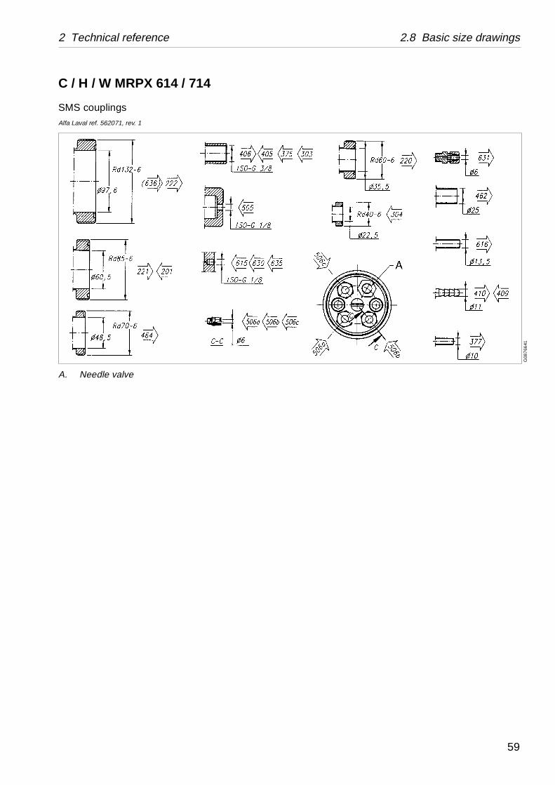
C / H / W MRPX 614 / 714
SMS couplingsAlfa Laval ref. 562071, rev. 1
A. Needle valve
59

2.8 Basic size drawings 2 Technical reference
Tightening torque 100 NmAdjusting washers, max. 4 pcs/footAlternative execution
le.
parators except BM / BB / HM / WM / RPX 818”
G0
876
6R1
C / H / W / MRPX 614 / 714
Clamp couplingsAlfa Laval ref. 562218, rev. 2
A. Maximum horizontal displacement at the outlet connections during operation ±20 mm
B. Maximum vertical displacement at the cyclone connection during operation ±10 mm
C.D.E.
Connection 220 and 221 turnable 360°.
All connections to be installed non-loaded and flexib
Data for connections, see ‘‘2.9 Connection list, all seon page 82.
60

2 Technical reference 2.8 Basic size drawings
G0
8766
61
C / H / W MRPX 614 / 714
Clamp couplingsAlfa Laval ref. 562218, rev. 2
A. Needle valve
61
2.8 Basic size drawings 2 Technical reference
Tightening torque 100 NmAdjusting washers, max. 4 pcs/footAlternative execution
le.
parators except BM / BB / HM / WM / RPX 818”
G08
766T
1
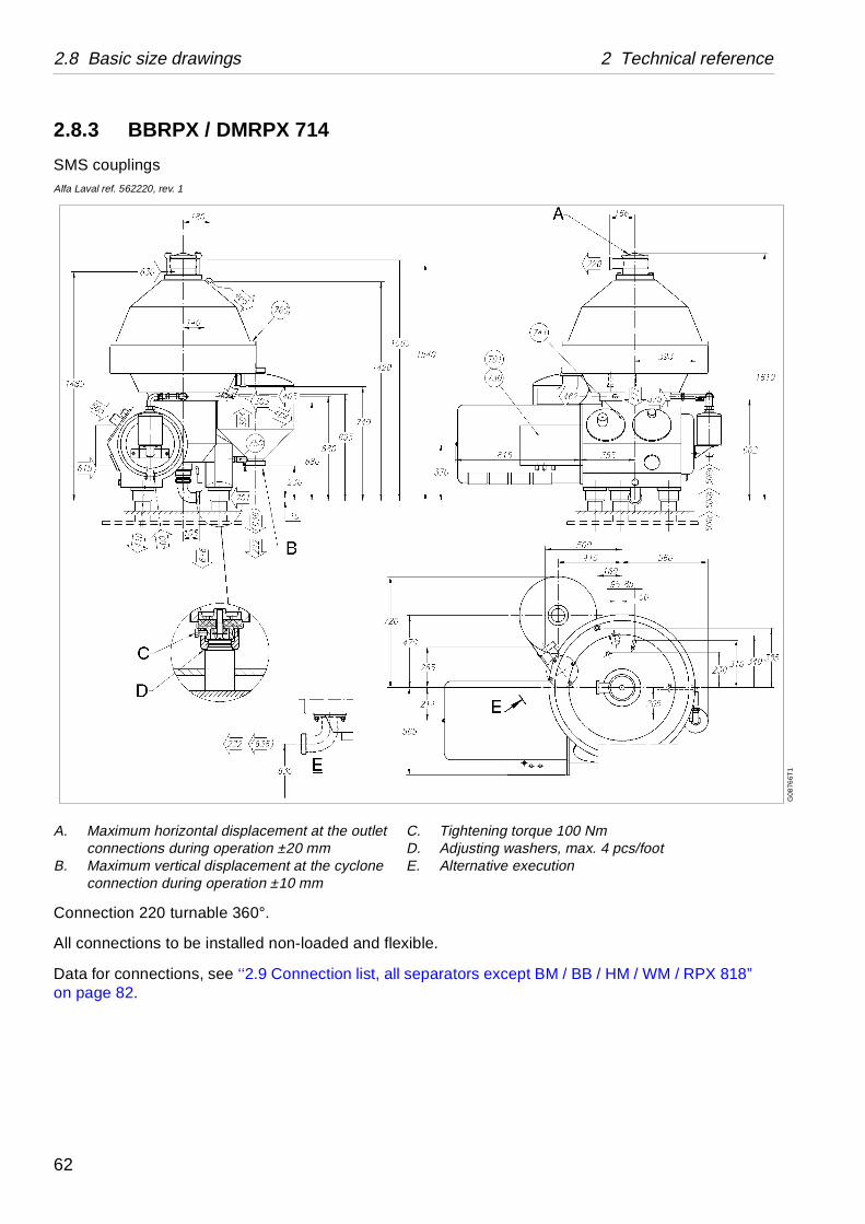
2.8.3 BBRPX / DMRPX 714
SMS couplingsAlfa Laval ref. 562220, rev. 1
A. Maximum horizontal displacement at the outlet connections during operation ±20 mm
B. Maximum vertical displacement at the cyclone connection during operation ±10 mm
C.D.E.
Connection 220 turnable 360°.
All connections to be installed non-loaded and flexib
Data for connections, see ‘‘2.9 Connection list, all seon page 82.
62

2 Technical reference 2.8 Basic size drawings
G08
766
A1
B BRPX / D MRPX 714
SMS couplingsAlfa Laval ref. 562220, rev. 1
A. Needle valve
63

2.8 Basic size drawings 2 Technical reference
Tightening torque 100 NmAdjusting washers, max. 4 pcs/footAlternative execution
le.
parators except BM / BB / HM / WM / RPX 818”
G0
8766
U1
2.8.4 C / H / W / MRPX 518 / 618
SMS couplingsAlfa Laval ref. 562224, rev. 1
A. Maximum horizontal displacement at the outlet connections during operation ±20 mm
B. Maximum vertical displacement at the cyclone connection during operation ±10 mm
C.D.E.
Connection 220 and 221 turnable 360°.
All connections to be installed non-loaded and flexib
Data for connections, see ‘‘2.9 Connection list, all seon page 82.
64

2 Technical reference 2.8 Basic size drawings
G08
766C
1
C / H / W MRPX 518 / 618
SMS couplingsAlfa Laval ref. 562224, rev. 1
A. Needle valve
65

2.8 Basic size drawings 2 Technical reference
Tightening torque 100 NmAdjusting washers, max. 4 pcs/footAlternative execution
le.
parators except BM / BB / HM / WM / RPX 818”
G0
8766
V1
C / H / W / MRPX 518 / 618
Clamp couplingsAlfa Laval ref. 562226, rev. 2
A. Maximum horizontal displacement at the outlet connections during operation ±20 mm
B. Maximum vertical displacement at the cyclone connection during operation ±10 mm
C.D.E.
Connection 221 and 220 turnable 360°.
All connections to be installed non-loaded and flexib
Data for connections: See ‘‘2.9 Connection list, all seon page 82.
66

2 Technical reference 2.8 Basic size drawings
G08
766E
1
C / H / W MRPX 518 / 618
Clamp couplingsAlfa Laval ref. 562226, rev. 2
A. Needle valve
67

2.8 Basic size drawings 2 Technical reference
Tightening torque 100 NmAdjusting washers, max. 4 pcs/footAlternative execution
le.
parators except BM / BB / HM / WM / RPX 818”
G0
8766
X1
2.8.5 B / F / MRPX 618,BMRPX 818
SMS couplingsAlfa Laval ref. 562228, rev. 2
A. Maximum horizontal displacement at the outlet connections during operation ±20 mm
B. Maximum vertical displacement at the cyclone connection during operation ±10 mm
C.D.E.
Connection 221 and 220 turnable 360°.
All connections to be installed non-loaded and flexib
Data for connections: See ‘‘2.9 Connection list, all seon page 82.
68

2 Technical reference 2.8 Basic size drawings
G08
766
Y1
B / F / MRPX 618, BMRPX 818
SMS couplingsAlfa Laval ref. 562228, rev. 2
A. Needle valve
69

2.8 Basic size drawings 2 Technical reference
Tightening torque 100 NmAdjusting washers, max. 4 pcs/footAlternative execution
le.
parators except BM / BB / HM / WM / RPX 818”
G08
766Z
1
B / F / MRPX 618, BMRPX 818
Clamp couplingsAlfa Laval ref. 562229, rev. 3
A. Maximum horizontal displacement at the outlet connections during operation ±20 mm
B. Maximum vertical displacement at the cyclone connection during operation ±10 mm
C.D.E.
Connection 221 and 220 turnable 360°.
All connections to be installed non-loaded and flexib
Data for connections: See ‘‘2.9 Connection list, all seon page 82.
70

2 Technical reference 2.8 Basic size drawings
G0
876
741
B / F / MRPX 618, BMRPX 818
Clamp couplingsAlfa Laval ref. 562229, rev. 3
A. Needle valve
71
2.8 Basic size drawings 2 Technical reference
Tightening torque 100 NmAdjusting washers, max. 4 pcs/footAlternative execution
le.
parators except BM / BB / HM / WM / RPX 818”
G0
9283
11
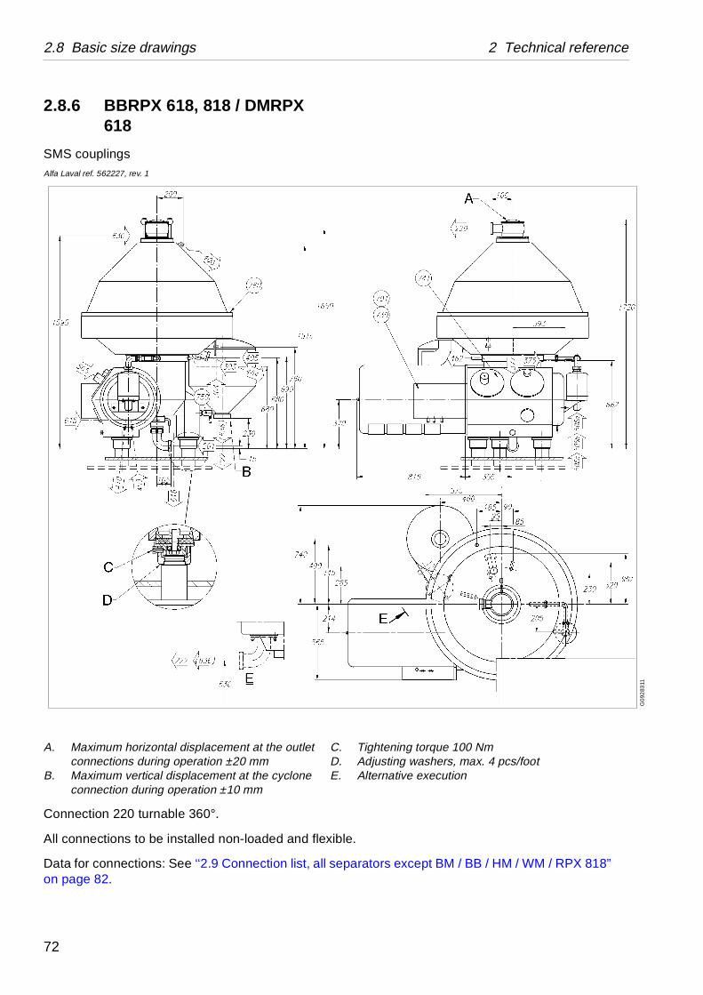
2.8.6 BBRPX 618, 818 / DMRPX 618
SMS couplingsAlfa Laval ref. 562227, rev. 1
A. Maximum horizontal displacement at the outlet connections during operation ±20 mm
B. Maximum vertical displacement at the cyclone connection during operation ±10 mm
C.D.E.
Connection 220 turnable 360°.
All connections to be installed non-loaded and flexib
Data for connections: See ‘‘2.9 Connection list, all seon page 82.
72

2 Technical reference 2.8 Basic size drawings
G0
8766
G1
BBRPX 618, 818 / DMRPX 618
SMS couplingsAlfa Laval ref. 562227, rev. 1
A. Needle valve
73

2.8 Basic size drawings 2 Technical reference
Tightening torque 100 NmAdjusting washers, max. 4 pcs/footAlternative execution
le.
parators except BM / BB / HM / WM / RPX 818” / WM / RPX 818” on page 86.
G0
928
411
2.8.7 H / W / C MRPX 718H / W / MRPX 818
SMS couplingsAlfa Laval ref. 562230, rev. 2
A. Maximum horizontal displacement at the outlet connections during operation ±20 mm
B. Maximum vertical displacement at the cyclone connection during operation ±10 mm
C.D.E.
Connection 220 and 221 turnable 360°.
All connections to be installed non-loaded and flexib
Data for connections, see ‘‘2.9 Connection list, all seon page 82 and ‘‘2.10 Connection list, BM / BB / HM
74

2 Technical reference 2.8 Basic size drawings
G0
8767
31
H / W / C MRPX 718H / W / MRPX 818
SMS couplingsAlfa Laval ref. 562230, rev. 2
A. Needle valve
75

2.8 Basic size drawings 2 Technical reference
Tightening torque 100 NmAdjusting washers, max. 4 pcs/footAlternative execution
le.
parators except BM / BB / HM / WM / RPX 818” / WM / RPX 818” on page 86.
G0
928
511
H / W / C MRPX 718H / W / MRPX 818
Clamp couplingsAlfa Laval ref. 562231, rev. 3
A. Maximum horizontal displacement at the outlet connections during operation ±20 mm
B. Maximum vertical displacement at the cyclone connection during operation ±10 mm
C.D.E.
Connection 220 and 221 turnable 360°.
All connections to be installed non-loaded and flexib
Data for connections, see ‘‘2.9 Connection list, all seon page 82 and ‘‘2.10 Connection list, BM / BB / HM
76

2 Technical reference 2.8 Basic size drawings
G08
7672
1
H / W / C MRPX 718H / W / MRPX 818
Clamp couplingsAlfa Laval ref. 562231, rev. 3
A. Needle valve
77
2.8 Basic size drawings 2 Technical reference
Tightening torque 100 NmAdjusting washers, max. 4 pcs/footAlternative execution
le.
parators except BM / BB / HM / WM / RPX 818” / WM / RPX 818” on page 86.
G0
9286
11
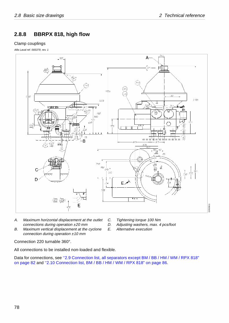
2.8.8 BBRPX 818, high flow
Clamp couplingsAlfa Laval ref. 565379, rev. 1
A. Maximum horizontal displacement at the outlet connections during operation ±20 mm
B. Maximum vertical displacement at the cyclone connection during operation ±10 mm
C.D.E.
Connection 220 turnable 360°.
All connections to be installed non-loaded and flexib
Data for connections, see ‘‘2.9 Connection list, all seon page 82 and ‘‘2.10 Connection list, BM / BB / HM
78

2 Technical reference 2.8 Basic size drawings
G0
928
621
BBRPX 818, high flow
Clamp couplingsAlfa Laval ref. 565379, rev. 1
A. Needle valve
79

2.8 Basic size drawings 2 Technical reference
Tightening torque 100 NmAdjusting washers, max. 4 pcs/footAlternative execution
le.
parators except BM / BB / HM / WM / RPX 818” / WM / RPX 818” on page 86.
G09
287
11
BBRPX 818, high flow
SMS couplingsAlfa Laval ref. 565380, rev. 1
A. Maximum horizontal displacement at the outlet connections during operation ±20 mm
B. Maximum vertical displacement at the cyclone connection during operation ±10 mm
C.D.E.
Connection 220 turnable 360°.
All connections to be installed non-loaded and flexib
Data for connections, see ‘‘2.9 Connection list, all seon page 82 and ‘‘2.10 Connection list, BM / BB / HM
80

2 Technical reference 2.8 Basic size drawings
G09
287
21
BBRPX 818, high flow
SMS couplingsAlfa Laval ref. 565380, rev. 1
A. Needle valve
81

2.9 Connection list, all separators except BM / BB / HM / WM / RPX 818 2 Technical
Requirements / limits
Max 600 kPa
0 – 700 kPa
p. only) 0 – 600 kPa
Max. 60 disch/hThe outlet from the cyclone should be installed in such a way that the cyclone can not be filled with sludge
e
ure)
100 – 600 kPa300 kPa460 litres/h0 - 6 litres / discharge
Ca 25 litres / discharge400 – 700 kPa
40 – 80 kPaMin. 5 litres/minsee ‘‘4.1 Service water” on page 110Max. 30 mMin. 10 x 1 mm
2.9 Connection list, all separators except BM / BB / HM / WM / RPX 818
Alfa Laval ref. 562178, rev. 1 / 562179, rev. 0
Connection No
Description
201 Inlet for process liquid• Pressure
220 Light phase (clarified liquid) outlet• Back pressure
221 Heavy phase outlet (twin phase se
222 Outlet for solid phase• Discharge interval
303 Flushing under the bowlNormally used only in the dischargsequence and / or for cleaning
• Pressure• Pressure (recommended)• Flow (momentary at rec. press• Consumption
304 Flushing in sediment outlet• Consumption• Pressure
375 Inlet for operating liquid• Pressure• Capacity• Quality requirements• Pipe length via a check valve• Pipe dimension
377 Outlet for operating liquid
82

2 Technical reference2.9 Connection list, all separators except BM / BB / HM / WM / RPX 818
Requirements / limits
100 litres/hMax. 50 kPaSee ‘‘4.1 Service water” on page 110
s No back pressure allowed
80 – 100 litres/hMax. 50 kPasee ‘‘4.1 Service water” on page 110
quality400 ± 50 kPasee ‘‘4.2 Compressed air” on page 111
300 – 700 kPasee ‘‘4.2 Compressed air” on page 111
300 – 700 kPasee ‘‘4.2 Compressed air” on page 111
300 – 700 kPasee ‘‘4.2 Compressed air” on page 111
DANGER
Disintegration hazard
Pressure in connections 405 and 406 must not be higher than 50 kPa. Risk for deformation of frame hood and consequent contact with rotating parts.
Connection No.
Description
405 Inlet for cooling liquid, frame part• Consumption• Pressure• Quality requirements
406 Outlet for cooling liquid, frame part
409 Inlet for liquid to oil cooler• Consumption• Pressure• Quality requirements
410 Outlet for liquid to oil cooler
462 Drain of frame top part, lower
464 Drain of frame top part
505 Inlet for compressed air to brake• Pressure• Compressed air, demands and
506 a Inlet for compressed air to OWMC• Pressure• Quality requirements
506 b Inlet for control of small discharge• Pressure• Quality requirements
506 c Inlet for control of large discharge• Pressure• Quality requirements
83

2.9 Connection list, all separators except BM / BB / HM / WM / RPX 818 2 Technical
60 – 80 litres/hsee ‘‘4.1 Service water” on page 110
Free outlet, without water trap
60 – 80 litres/hsee ‘‘4.1 Service water” on page 110
60 – 80 litres/hsee ‘‘4.1 Service water” on page 110
ncy
see ‘‘2.3 Motor drive data (CT-motors)” on page 34± 5%
ing
Contact the supplier representative.
n)
AMUR
tal)rom
Contact the supplier representative.
see ‘‘2.11 Interconnection diagram” on page 908 V
less than 1 mA, (typical 0,7 mA)
greater than 3 mA, (typical 6 mA)
4
r speed t be uration
Requirements / limits
615 Inlet for sealing liquid• Consumption• Quality requirements
616 Outlet for sealing liquid
630 Inlet for sealing liquid• Consumption• Quality requirements
631 Outlet for sealing liquid
635 Inlet for sealing liquid• Consumption• Quality requirements
(636) Outlet for sealing liquid
701 Motor for separatorTechnical data:
Max. deviation from nominal freque
730 Temperature sensor for motor windType: PTC thermistor
Technical data:
741 a Speed sensor for motor shaft (optio
Electrical data:Type: Inductive proximity switch, NtypeFor technical data:
Connection:
Supply voltage, nominalOutput current:• With sensor activated (near me• With sensor not activated (far f
metal)
Number of pulses per revolution
The secondary switching device foindicating and alarm functions muscapable of handling pulses with a dof 0,5 ms
Connection No.
Description
84

2 Technical reference2.9 Connection list, all separators except BM / BB / HM / WM / RPX 818
n)
NP typeContact the supplier representative.10 - 30 V DCMax. 200 mA‘‘2.11 Interconnection diagram” on page 90
plier
100 mV / mm / s10 – 2000 Hz
Requirements / limits
741 b Speed sensor for motor shaft (optio
Electrical data:Type: Inductive proximity switch, PFor technical data:
Supply voltageOutput currentConnection
750 Vibration sensor (option)Type: Vibration velocity transducerFor technical data: Contact the suprepresentative.Signal output at 80 Hz RL ≥ 1 MohmFrequency range
760 Cover interlocking switch (option)
Type: Double, two-way microswitch
Connection No.
Description
85

2.10 Connection list, BM / BB / HM / WM / RPX 818 2 Technical reference
Requirements / limits
Max 700 kPa
0 – 700 kPa
p. only) 0 – 600 kPa
Max. 60 disch/hThe outlet from the cyclone should be installed in such a way that the cyclone can not be filled with sludge
e
ure)
100 – 600 kPa300 kPa460 litres/h0 - 6 litres / discharge
Ca 25 litres / discharge400 – 700 kPa
40 – 80 kPaMin. 5 litres/minsee ‘‘4.1 Service water” on page 110Max. 30 mMin. 10 x 1 mm
2.10 Connection list,BM / BB / HM / WM / RPX 818
Alfa Laval ref. 564659, rev. 1 / 565381, rev. 0
Connection No
Description
201 Inlet for process liquid• Pressure
220 Light phase outlet• Back pressure
221* Heavy phase outlet (twin phase se
222 Outlet for solid phase• Discharge interval
303 Flushing under the bowlNormally used only in the dischargsequence and / or for cleaning
• Pressure• Pressure (recommended)• Flow (momentary at rec. press• Consumption
304 Flushing in sediment outlet• Consumption• Pressure
375 Inlet for operating liquid• Pressure• Capacity• Quality requirements• Pipe length via a check valve• Pipe dimension
377 Outlet for operating liquid
*Only H / W / B / MRPX 818
86

2 Technical reference 2.10 Connection list, BM / BB / HM / WM / RPX 818
Requirements / limits
100 litres/hMax. 50 kPaSee ‘‘4.1 Service water” on page 110
s No back pressure allowed
80 – 100 litres/hMax. 50 kPasee ‘‘4.1 Service water” on page 110
quality400 ± 50 kPasee ‘‘4.2 Compressed air” on page 111
300 – 700 kPasee ‘‘4.2 Compressed air” on page 111
350 – 700 kPasee ‘‘4.2 Compressed air” on page 111
350 – 700 kPasee ‘‘4.2 Compressed air” on page 111
60 – 80 litres/hsee ‘‘4.1 Service water” on page 110
Free outlet, without water trap
60 – 80 litres/hsee ‘‘4.1 Service water” on page 110
Connection No.
Description
405 Inlet for cooling liquid, frame part• Consumption• Pressure• Quality requirements
406 Outlet for cooling liquid, frame part
409 Inlet for liquid to oil cooler• Consumption• Pressure• Quality requirements
410 Outlet for liquid to oil cooler
462 Drain of frame top part, lower
464 Drain of frame top part
505 Inlet for compressed air to brake• Pressure• Compressed air, demands and
506 a Inlet for compressed air to OWMC• Pressure• Quality requirements
506 b Inlet for control of small discharge• Pressure• Quality requirements
506 c Inlet for control of large discharge• Pressure• Quality requirements
615 Inlet for sealing liquid• Consumption• Quality requirements
616 Outlet for sealing liquid
630 Inlet for sealing liquid• Consumption• Quality requirements
631* Outlet for sealing liquid
87

2.10 Connection list, BM / BB / HM / WM / RPX 818 2 Technical reference
60 – 80 litres/hsee ‘‘4.1 Service water” on page 110
ncy
see ‘‘2.3 Motor drive data (CT-motors)” on page 34± 5%
ing
Contact the supplier representative.
n)
AMUR
tal)rom
Contact the supplier representative.
see ‘‘2.11 Interconnection diagram” on page 908 V
less than 1 mA, (typical 0,7 mA)
greater than 3 mA, (typical 6 mA)
4
r speed t be uration
n)
NP typeContact the supplier representative.
10 - 30 V DCMax. 200 mA‘‘2.11 Interconnection diagram” on page 90
Requirements / limits
635* Inlet for sealing liquid• Consumption• Quality requirements
(636) Outlet for sealing liquid
701 Motor for separatorTechnical data:
Max. deviation from nominal freque
730 Temperature sensor for motor windType: PTC thermistor
Technical data:
741 a Speed sensor for motor shaft (optio
Electrical data:Type: Inductive proximity switch, NtypeFor technical data:
Connection:
Supply voltage, nominalOutput current:• With sensor activated (near me• With sensor not activated (far f
metal)
Number of pulses per revolution
The secondary switching device foindicating and alarm functions muscapable of handling pulses with a dof 0,5 ms
741 b Speed sensor for motor shaft (optio
Electrical data:Type: Inductive proximity switch, PFor technical data:
Supply voltageOutput currentConnection
Connection No.
Description
88

2 Technical reference 2.10 Connection list, BM / BB / HM / WM / RPX 818
Contact the supplier representative.
100 mV / mm / s10 – 2000 Hz
Requirements / limits
750 Vibration sensor (option)Type: Vibration velocity transducerFor technical data:
Signal output at 80 Hz RL ≥ 1 MohmFrequency range
760 Cover interlocking switch (option)
Type: Double, two-way microswitch
Connection No.
Description
89

2.11 Interconnection diagram 2 Technical reference
otor shaft speed), NAMUR or PNP type
otor shaft speed), NAMUR or PNP type
elocity transducer)
(frame top part)n cover not fitted
G0
6947
31
2.11 Interconnection diagram
Optional equipmentAlfa Laval ref. 562208, rev. 0
Wire colour codes:BK = blackBN = brownBU = blueGN-YW = green-yellow
SIG = signal
741a - Speed sensor (m
741b - Speed sensor (m
750 - Vibration sensor (v
760 -Interlocking switch Normally open whe
A. Ferrite core
90

3 Interface description
Contents
3.1 Interface description,standard motor, frequency drive 92
3.1.1 General 92
3.1.2 Definitions 92
3.1.3 Requirements (normative) 94
3.1.4 Recommendations (informative) 98
3.1.5 Function graph andrunning limitations 99
3.2 Interface description, CT-motor 100
3.2.1 General 100
3.2.2 Definitions 100
3.2.3 Requirements (normative) 102
3.2.4 Recommendations (informative) 106
3.2.5 Function graph andrunning limitations 107
91

3.1 Interface description, standard motor, frequency drive 3 Interface description
3.1 Interface description, standard motor, frequency drive
Alfa Laval ref. 562168, rev. 0
3.1.1 General
This document describes limitations and conditions for safe control, monitoring and reliable operation. Further information is found in ‘‘2.9 Connection list, all separators except BM / BB / HM / WM / RPX 818” on page 82 and ‘‘2.10 Connection list, BM / BB / HM / WM / RPX 818” on page 86 . The document contains definitions, requirements (normative) and recommendations (informative) at the end of the document a function graph with running limitations.
3.1.2 Definitions
”Stand still” means:
• The separator is correctly assembled.
• All connections are made according to Connection List, Interconnection Diagram, Motor Drive Data and Interface Description.
• The electrical power to the separator control system is on or off.
”Start mode” means:
• Start to be initiated from position close to separator (not remotely).
• The electrical power to the separator motor is on.
• The acceleration must be supervised to ensure that a certain speed has been reached within a certain time.
”Running mode” means:
• ”Running mode” is in effect 1 minute after the time 98% of synchronous speed has been reached.
• The feed to the separator is on or off.
92
3 Interface description 3.1 Interface description, standard motor, frequency drive
”Stop mode” means:
• The electrical power to the separator motor is off.
• ”Stop mode” is in effect until the separator has stopped completely.
”Normal stop” means:
• Stopping of the separator, manually or automatically, at any time with or without brake applied.
• The bowl shall be kept filled.
• Sludge discharge must not be made.
”Safety st op” means:
A stop due to unsafe conditions (e.g. vibrations) automatically initiated by the control system. The separator shall be automatically stopped in the quickest and safest way possible. Comply with following conditions:
• The bowl shall be kept filled.
• Sludge discharge must not be made.
• The separator shall not be restarted before the reason for the ”Safety stop” has been investigated and action has been taken.
”Emergency stop” means:
A manually initiated stop due to emergency.
Actions:
• Same as for ”Safety stop” but with consideration to what is described in EN 418.
93

3.1 Interface description, standard motor, frequency drive 3 Interface description
G0
8779
21
���1HHGOH�YDOYH�$OO�QXPEHUV�DUH�H[SODLQHG�LQ�WKH�2SHUDWRU¶V�0DQXDO��
3.1.3 Requirements (normative)
506 Air connection for OWMC (operating water module)
The separator is equipped with a pneumatic controlled operating water module.
When compressed air is supplied to connection 506a, the discharge can be initiated from the control system via two pneumatic inputs (valves), one input for the small discharge, connection 506b and one for the large discharge, connection 506c. Allowed pressures to each connection, see ‘‘2.9 Connection list, all separators except BM / BB / HM / WM / RPX 818” on page 82 and ‘‘2.10 Connection list, BM / BB / HM / WM / RPX 818” on page 86.
The volume of the large discharge should be adjusted first by adding various inlet pressure to connection 506a. When the large discharge volume has been set, the small discharge volume can be adjusted with the needle valve (8) fitted on the OWMC-unit.
Activating time for the control inputs shall be min. 5 seconds in the discharge sequence.
701 Separator motor
The separator is equipped with a 3-phase standard motor. The motor is fed from a frequency converter.
The frequency converter must have overspeed alarm function which stops the separator if the speed exceeds the nominal synchronous speed more than 5%.
730 Motor temperature sensor
The separator motor is equipped with three thermistor sensors, one in each winding. The sensors are connected in series and should be connected to a thermistor relay that trips and interlocks the frequency converter and initiates a Normal Stop without brake when the temperature exceeds the tripping level, see Motor Drive Data.
94

3 Interface description 3.1 Interface description, standard motor, frequency drive
741a Speed sensor
Proximity sensor of inductive type PNP or NAMUR standard giving number of pulses per revolution of the motor shaft. See ‘‘2.9 Connection list, all separators except BM / BB / HM / WM / RPX 818” on page 82 and ‘‘2.10 Connection list, BM / BB / HM / WM / RPX 818” on page 86.The bowl speed is gear ratio (see ‘‘2.2 Technical data” on page 19) multiplied by the speed of the motor shaft.
741b Speed sensor (option)
The bracket for the speed sensor and the junction box is prepared for an extra speed sensor, if needed.
Signal processing in ”Start mode”:
• The separator shall be stopped automatically according to ”Normal stop” procedure, and a low speed alarm shall be given when the accumulated time for acceleration is longer than the maximum time specified in ‘‘2.2 Technical data” on page 19. An abnormal start time indicates some malfunction of the separator equipment and should be investigated.
• If the speed exceeds the nominal synchronous speed with more than 5%, the separator shall be stopped automatically according to ”Normal stop” procedure, and a high speed alarm shall be given. Excessive bowl speeds generate stress levels to the material that can be damaging.
• In case of sudden lack of pulses from the speed sensor, the separator shall be stopped automatically according to ”Safety stop” procedure with a timer controlled stop sequence, and an alarm for speed sensor failure shall be given.
95

3.1 Interface description, standard motor, frequency drive 3 Interface description
Signal processing in ”Running mode”:
The running speed is obtained when the 98% of the synchronous speed has been reached.
• If the speed exceeds the nominal synchronous speed with more than 5%, the separator shall be stopped automatically according to ”Safety stop” procedure, and a high speed alarm shall be given. Excessive bowl speeds generate stress levels to the material that can be damaging.
• If the speed falls more than 5% below the synchronous speed for a period longer than 1 minute, a low speed alarm shall be given. Low speed indicates some malfunction of the separator equipment and should be investigated.
• In case of sudden lack of pulses from the speed sensor an alarm for speed sensor failure shall be given.
750 Unbalance sensor
For indication of any abnormal unbalance and to be able to perform appropriate countermeasures, the separator has been equipped with a vibration velocity transducer on the separator frame. The signal from the transducer shall be monitored, and two alarm levels according to the vibration alarm levels in ‘‘2.2 Technical data” on page 19 shall be set.
The vibration monitor shall include a safety, self check function to be performed at initiation of ”Start mode”, ”Running mode” and ”Stop mode”. That means that if any part of the complete Unbalance Sensor System fails an alarm shall be given and action must be taken.
96

3 Interface description 3.1 Interface description, standard motor, frequency drive
Signal processing in ”Start mode”:
• If vibrations exceed the second alarm level, the separator shall be stopped automatically according to ”Safety stop” procedure. Vibrations of this magnitude might generate severe damages and the cause must be eliminated immediately.
• For bowl speeds in the span 600 to 1000 r/min vibration monitoring must be blocked. This is to eliminate alarm triggering from (normal) vibrations when the speed passes the critical speed.
• If the self check system triggers, an alarm shall be given and an automatic stop according to ”Safety stop” procedure should be initiated.
Signal processing in ”Running mode”:
• If vibrations exceed the first alarm level, an alarm shall be given. Vibrations of this magnitude will reduce the expected life time of the bearings and should therefore be eliminated.
• If vibrations exceed the second alarm level, the separator shall be stopped automatically according to ”Safety stop” procedure. Vibrations of this magnitude might generate severe damages, and the cause must be eliminated immediately.
• Vibration monitoring shall be blocked for 5 seconds from initiation of a discharge. Unwanted alarms are in this way eliminated as high vibrations during discharge are normal.
Signal processing in ”Stop mode”:
• If the self check system triggers, an alarm shall be given, and an automatic stop according to ”Safety stop” procedure should be initiated.
97

3.1 Interface description, standard motor, frequency drive 3 Interface description
3.1.4 Recommendations (informative)
760 Cover interlocking switch
The separator is equipped with an interlocking switch to detect if the cover is mounted.
Signal processing during ”Stand still”:
• The circuit is closed when the cover of the separator is mounted.
• The interlocking switch should be connected in such a way that starting of the motor (”Start mode”) is prevented when the separator cover is not mounted.
Signal processing in ”Running mode”:
• If the circuit is broken, an alarm should be given. This is to minimise the risk of having access to moving parts.
Discharge system
Signal processing in ”Running mode”:
At indication of the absence of a discharge the operator or the control system must initiate a new discharge and corrective action must be taken. The occurrence of a discharge can for instance be monitored with the aid of a system for checking the rise of separator motor electrical current. Absence of a discharge may result in problems due to solidification of the sludge.
98

3 Interface description 3.1 Interface description, standard motor, frequency drive
G0
543
211
3.1.5 Function graph and running limitations
A. Stand still (Ready for start)B. Starting modeC. Running modeD. Stop modeE. Safety or emergency stop
99

3.2 Interface description, CT-motor 3 Interface description
3.2 Interface description, CT-motor
Alfa Laval ref. 562167, rev. 0
3.2.1 General
This document describes limitations and conditions for safe control, monitoring and reliable operation. Further information is found in ‘‘2.9 Connection list, all separators except BM / BB / HM / WM / RPX 818” on page 82 and ‘‘2.10 Connection list, BM / BB / HM / WM / RPX 818” on page 86. The document contains definitions, requirements (normative) and recommendations (informative) at the end of the document a function graph with running limitations.
3.2.2 Definitions
”Stand still” means:
• The separator is correctly assembled.
• All connections are made according to Connection List, Interconnection Diagram, Motor Drive Data and Interface Description.
• The electrical power to the separator control system is on or off.
”Start mode” means:
• Start to be initiated from position close to separator (not remotely).
• The electrical power to the separator motor is on.
• The acceleration must be supervised to ensure that a certain speed has been reached within a certain time.
”Running mode” means:
• ”Running mode” is in effect 1 minute after the time 93% of synchronous speed has been reached.
• The feed to the separator is on or off.
100

3 Interface description 3.2 Interface description, CT-motor
”Stop mode” means:
• The electrical power to the separator motor is off.
• ”Stop mode” is in effect until the separator has stopped completely.
”Normal stop” means:
• Stopping of the separator, manually or automatically, at any time with or without brake applied.
• The bowl shall be kept filled.
• Sludge discharge must not be made.
”Safety st op” means:
A stop due to unsafe conditions (e.g. vibrations) automatically initiated by the control system. The separator shall be automatically stopped in the quickest and safest way possible. Comply with following conditions:
• The bowl shall be kept filled.
• Sludge discharge must not be made.
• The separator shall not be restarted before the reason for the ”Safety stop” has been investigated and action has been taken.
”Emergency stop” means:
A manually initiated stop due to emergency.
Actions:
• Same as for ”Safety stop” but with consideration to what is described in EN 418.
101
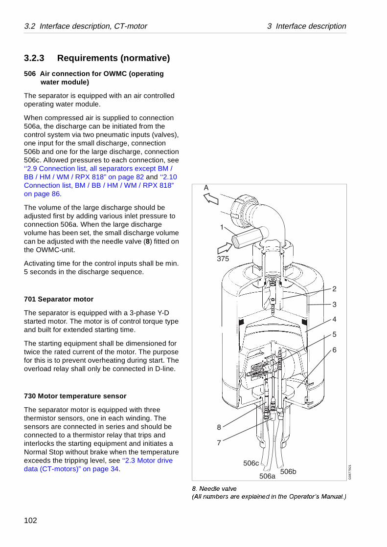
3.2 Interface description, CT-motor 3 Interface description
G08
779
21
���1HHGOH�YDOYH�$OO�QXPEHUV�DUH�H[SODLQHG�LQ�WKH�2SHUDWRU¶V�0DQXDO��
3.2.3 Requirements (normative)
506 Air connection for OWMC (operating water module)
The separator is equipped with an air controlled operating water module.
When compressed air is supplied to connection 506a, the discharge can be initiated from the control system via two pneumatic inputs (valves), one input for the small discharge, connection 506b and one for the large discharge, connection 506c. Allowed pressures to each connection, see ‘‘2.9 Connection list, all separators except BM / BB / HM / WM / RPX 818” on page 82 and ‘‘2.10 Connection list, BM / BB / HM / WM / RPX 818” on page 86.
The volume of the large discharge should be adjusted first by adding various inlet pressure to connection 506a. When the large discharge volume has been set, the small discharge volume can be adjusted with the needle valve (8) fitted on the OWMC-unit.
Activating time for the control inputs shall be min. 5 seconds in the discharge sequence.
701 Separator motor
The separator is equipped with a 3-phase Y-D started motor. The motor is of control torque type and built for extended starting time.
The starting equipment shall be dimensioned for twice the rated current of the motor. The purpose for this is to prevent overheating during start. The overload relay shall only be connected in D-line.
730 Motor temperature sensor
The separator motor is equipped with three thermistor sensors, one in each winding. The sensors are connected in series and should be connected to a thermistor relay that trips and interlocks the starting equipment and initiates a Normal Stop without brake when the temperature exceeds the tripping level, see ‘‘2.3 Motor drive data (CT-motors)” on page 34.
102

3 Interface description 3.2 Interface description, CT-motor
741a Speed sensor
Proximity sensor of inductive type PNP or NAMUR standard giving number of pulses per revolution of the motor shaft. See ‘‘2.9 Connection list, all separators except BM / BB / HM / WM / RPX 818” on page 82 and ‘‘2.10 Connection list, BM / BB / HM / WM / RPX 818” on page 86. The bowl speed is gear ratio (see ‘‘2.2 Technical data” on page 19) multiplied by the speed of the motor shaft.
741b Speed sensor (option)
The bracket for the speed sensor and the junction box is prepared for an extra speed sensor, if needed.
Signal processing in ”Start mode”:
When the speed of 93% of the synchronous speed is reached, the Y-D starting equipment should switch over to D.
• The separator shall be stopped automatically according to ”Normal stop” procedure, and a low speed alarm shall be given when the accumulated time for acceleration is longer than the maximum time specified in ‘‘2.2 Technical data” on page 19. An abnormal start time indicates some malfunction of the separator equipment and should be investigated.
• If the speed exceeds the nominal synchronous speed with more than 5%, the separator shall be stopped automatically according to ”Normal stop” procedure, and a high speed alarm shall be given. Excessive bowl speeds generate stress levels to the material that can be damaging.
• In case of sudden lack of pulses from the speed sensor, the separator shall be stopped automatically according to ”Safety stop” procedure with a timer controlled stop sequence, and an alarm for speed sensor failure shall be given.
103

3.2 Interface description, CT-motor 3 Interface description
Signal processing in ”Running mode”:
The running speed is obtained when the 98% of the synchronous speed has been reached.
• If the speed exceeds the nominal synchronous speed with more than 5%, the separator shall be stopped automatically according to ”Safety stop” procedure, and a high speed alarm shall be given. Excessive bowl speeds generate stress levels to the material that can be damaging.
• If the speed falls more than 5% below the synchronous speed for a period longer than 1 minute, a low speed alarm shall be given. Low speed indicates some malfunction of the separator equipment and should be investigated.
• In case of sudden lack of pulses from the speed sensor an alarm for speed sensor failure shall be given.
750 Unbalance sensor
For indication of any abnormal unbalance and to be able to perform appropriate countermeasures, the separator has been equipped with a vibration velocity transducer on the separator frame. The signal from the transducer shall be monitored, and two alarm levels according to the vibration alarm levels in ‘‘2.2 Technical data” on page 19 shall be set.
The vibration monitor shall include a safety, self check function to be performed at initiation of ”Start mode”, ”Running mode” and ”Stop mode”. That means that if any part of the complete Unbalance Sensor System fails, an alarm shall be given and action must be taken.
104

3 Interface description 3.2 Interface description, CT-motor
Signal Processing in ”Start mode”:
• If vibrations exceed the second alarm level, the separator shall be stopped automatically according to ”Safety stop” procedure. Vibrations of this magnitude might generate severe damages, and the cause must be eliminated immediately.
• For bowl speeds in the span 600 to 1000r/min vibration monitoring must be blocked. This is to eliminate alarm triggering from (normal) vibrations when the speed passes the critical speed.
• If the self check system triggers, an alarm shall be given and an automatic stop according to ”Safety stop” procedure should be initiated.
Signal Processing in ”Running mode”:
• If vibrations exceed the first alarm level, an alarm shall be given. Vibrations of this magnitude will reduce the expected life time of the bearings and should therefore be eliminated.
• If vibrations exceed the second alarm level, the separator shall be stopped automatically according to ”Safety stop” procedure. Vibrations of this magnitude might generate severe damages, and the cause must be eliminated immediately.
• Vibration monitoring shall be blocked for 5 seconds from initiation of a discharge. Unwanted alarms are in this way eliminated as high vibrations during discharge are normal.
Signal Processing in ”Stop mode”:
• If the self check system triggers, an alarm shall be given, and an automatic stop according to ”Safety stop” procedure should be initiated.
105

3.2 Interface description, CT-motor 3 Interface description
3.2.4 Recommendations (informative)
760 Cover interlocking switch
The separator is equipped with an interlocking switch to detect if the cover is mounted.
Signal processing during ”Stand still”:
• The circuit is closed when the cover of the separator is mounted.
• The interlocking switch should be connected in such a way that starting of the motor (”Start mode”) is prevented when the separator cover is not mounted.
Signal processing in ”Running mode”:
• If the circuit is broken, an alarm should be given. This is to minimise the risk of having access to moving parts.
Discharge system
Signal processing in ”Running mode”:
At indication of the absence of a discharge the operator or the control system must initiate a new discharge and corrective action must be taken. The occurrence of a discharge can for instance be monitored with the aid of a system for checking the rise of separator motor electrical current. Absence of a discharge may result in problems due to solidification of the sludge.
106

3 Interface description 3.2 Interface description, CT-motor
G0
543
211
3.2.5 Function graph and running limitations
A. Stand still (Ready for start)B. Starting modeC. Running modeD. Stop modeE. Safety or emergency stop
107

3.2 Interface description, CT-motor 3 Interface description
108

4 Demand specification
Contents
4.1 Service water 110
4.2 Compressed air 111
109

4.1 Service water 4 Demand specification
different functions: e.g. to operate the ical seals, etc.
use erosion, corrosion and/or re be treated to meet certain
PSRUWDQFH
volume.
areas in the separator.
, which corresponds to 10 °dH or
erating mechanism. The precipitation perature and low discharge he harder the water is.
t to 60 mg Cl/l).
rator surfaces in contact with the is a process that is accelerated by
high chloride ion concentration.
commended.
or corrosion; this is accelerated by tent.
4.1 Service waterAlfa Laval ref. 553406, rev. 5
Operating water is used in the separator for several discharge mechanism, to lubricate and cool mechan
Poor quality of the operating water may with time caoperating problem in the separator and must therefodemands.
7KH�IROORZLQJ�UHTXLUHPHQWV�DUH�RI�IXQGDPHQWDO�L
1.1 Turbidity-free water, solids content <0,001% by
Deposits must not be allowed to form in certain
1.2 Max particle size 50 µm.
2. Total hardness less than 180 mg CaCO3 per litre12,5 °E.
Hard water may with time form deposits in the oprate is accelerated with increased operating temfrequency. These effects become more severe t
3. Chloride content max 100 ppm NaCl (equivalen
Chloride ions contribute to corrosion on the sepaoperating water, including the spindle. Corrosionincreased separating temperature, low pH, and
A chloride concentration above 60 mg/l is not re
4. pH>6
Increased acidity (lower pH) increases the risk fincreased temperature and high chloride ion con
NOTE
Alfa Laval accepts no liability for consequences arising from unsatisfactorily purified operating water supplied by the customer.
110

4 Demand specification 4.2 Compressed air
e system, valve uch a quality that e.
below 10 micron preferably done ovided with filters.
rom oil-lubricated st possible hich it is difficult r oil separators nts. In small
alternative.
kes place at t at the air inlet, r, partially lower e (outdoor, cellar
est temperature ate in the be cooled d nozzles in the
ew of the above,
compressed air nt temperature. drier of suitable a primary
able and s, and exchange
4.2 Compressed airAlfa Laval ref. 553407, rev. 2
The supply of compressed air to separator dischargactuators, positioners, instruments etc. must be of ssatisfactory function is ensured for a reasonable tim
To this end three conditions must be fulfilled:
1. Dirt in the form of solid particles down to a size (0,01 mm) must be removed from the air. This isby means of special filters or reducing valves pr
2. Oil is always transferred to the compressed air fcompressors and must be removed to the highedegree. It constitutes a serious contamination, wto remove from the instruments. Special filters omust, therefore, be provided before the instrumeplants, oil-free compressors can be used as an
3. In the compressed-air system a condensation tavarious rates, depending on the moisture contenthe temperature before and after the compressotemperature in any cold zone passed by the pipetc.) and the like.
The air must thus be dried with regard to the lowexisting after the drying device, so that condensinstruments is avoided. Note that the air will alsothrough expansion after passing constrictions aninstruments, with condensation as a result. In vithe following must be observed:
At the inlet to an instrument, the dew point of theshould lie at least 10 °C below the lowest ambieThis is usually obtained by using an absorption capacity. If the air contains much water, provideseparator before the filter.
Air filters should be placed so as to be easily surveyaccessible in order to facilitate daily condition checkof the filter cartridge.
NOTE
Alfa Laval accepts no liability for consequences arising from unsatisfactorily purified compressed air supplied by the customer.
111

4.2 Compressed air 4 Demand specification
112

5 Installation and first start
Contents
5.1 Preparations 114
5.2 Before first start 115
5.3 First start 116
5.4 Operation 116
5.4.1 Ejection process 117
5.4.2 Cleaning 117
5.4.3 Separation 118
5.4.4 Operation 118
5.5 Stopping 118
5.6 Selection of outlet impeller(twin phase separators) 119
5.6.1 Permissible inlet andoutlet pressures 119
5.6.2 Flow / outlet pressure 120
5.6.3 Permissible inlet andoutlet pressures, B MRPX 618 122
5.6.4 Permissible inlet andoutlet pressures forC / H MRPX 518 / 618 / 718 andH MRPX 818 124
113

5.1 Preparations 5 Installation and first start
G06
659
11
5.1 Preparations1. Set up the machine (without frame hood and
bowl) according to the installation instructions.
2. Flush the piping thoroughly to remove any residues such as chips, welding beads, etc.
3. Check the operating water functions and operating water flow as below.
Checking the operating water flow.
When operating water is fed (375*) water shall squirt out of the holes in weak jets.
During operation there will be no consumption of water when the pressure is lower than 50 kPa (0,5 bar).
At discharge water shall squirt out of the holes in powerful jets.
4. Check that the water flow-rates correspond to data in ‘‘2.9 Connection list, all separators except BM / BB / HM / WM / RPX 818” on page 82 and ‘‘2.10 Connection list, BM / BB / HM / WM / RPX 818” on page 86:− Water for lubrication oil cooler 409*.− Water for discharge 375*.− Water for cooling frame parts 405*.
*) Numbers refer to ‘‘2.9 Connection list, all separators except BM / BB / HM / WM / RPX 818” on page 82 and ‘‘2.10 Con-nection list, BM / BB / HM / WM / RPX 818” on page 86.
NOTE
All piping must be disconnected from the separator.
NOTE
Outlet 464* must be open. No restrictions allowed.
114

5 Installation and first start 5.1 Before first start
S01
178
11S
0117
911
S01
180
21
S0
118
111
G06
992
21
5.2 Before first start• Pour about 13 litres lubricating oil of correct
grade into the worm gear housing – see chapter “Lubricants” in the Service & Maintenance Manual.
• Check the oil (approx. half way up the sight glass). Be aware of that a very small quantity of oil may remain at the bottom edge of the sight glass even when the gear housing is emptied for oil.
• Assemble the bowl and the inlet and outlet parts as described in the Service & Maintenance Manual.
• Make sure that the frame hood bolts have been tightened.
• Make sure that the bolts for centring ring and outlets have been tightened to the correct torque. See the Service & Maintenance Manual.
• Make sure that the bolts for the inlet device have been tightened.
• Check that water and air are being supplied to the control panel.
Make sure that cooling water is being supplied to the separator.
Check at
(1) – from inlet device seal
(2) – from outlet upper seals (twin phase separators)
(3) – from outlet bottom seal (at operation).
115

5.3 First start 5 Installation and first start
S0
1182
11
Revolution counter
5.3 First start• Start the machine
• Check the direction of rotation (see revolution counter).
• When the bowl has reached running speed, check the revolution counter reading. For speed particulars, see ‘‘2.2 Technical data” on page 19.
The bowl is now closed (provided that make-up water has been supplied during the run-up period).
• Make sure that the valves in the outlets are open.
5.4 Operation• With the bowl closed, supply water to the
bowl (start the feed pump).
• Make sure that the separation inlet pressure is suitable and the throughput correct. Then check outlet pressures, see “Selection of outlet impeller” in Operator’s Manual.
• Shut off the cooling water to the axial seals.
NOTE
At the switch-over to D the amperage will increase considerably, but will quickly drop towards the idling level provided that the motor is correctly connected. If the amperage remains at the high level, the motor has been wrongly connected. Stop the motor immediately.
NOTE
It is important to have liquid flow through the bowl.
116

5 Installation and first start 5.3 Operation
S0
118
311
• Check that the bowl is tightly closed – no water in the cyclone outlet.
• Disconnect the pipes for cooling water to the outlet seals. Check for possible leakage from these. Major leaks must not occur. Minor leaks may temporarily be left uncorrected. Some seals need as a rule certain wear-in period.
• Connect the pipes for cooling water.
• Open the cooling water supply again.
5.4.1 Ejection process
• Disconnect the pipe from the cyclone as well as the sediment cover flushing hose.
• Make the settings of the Operating Water Module to achieve the discharge volumes desired, see chapter ‘‘3.1.3 Requirements (normative)” on page 94.
• Initiate a large discharge. If the bowl opens, closes and the opens again (so-called double discharge), adjust the air pressure until you arrive at the volume desired. Finally adjust the needle valve to achieve a suitable small discharge.
• Secure the cyclone outlet pipe and the sediment cover flushing pipe.
5.4.2 Cleaning
• Carry out the cleaning programme. Check that washing solution is running out of the axial seals.
WARNING
Liquid ejected at high velocity
Ensure that no sediment discharge takes place when opening cyclone cover. Wear safety goggles.
117

5.3 Stopping 5 Installation and first start
S0
118
411
5.4.3 Separation
• Supply process liquid.
• Check the inlet pressure, see “Selection of outlet impeller” in Operator’s Manual.
• Adjust the outlet pressures, see “Selection of outlet impeller” in Operator’s Manual.
5.4.4 Operation
• Check the throughput. Make a final adjustment of inlet and outlet pressures.
• Make sure that no air is being sucked into the feed pipe via e.g.a balance vessel, if fitted. This should always be kept filled. The process liquid should flow evenly in the vessel without bubbling.
After separation is completed, carry out the cleaning programme. Dismantle the bowl and check the cleaning 3 – 4 days after the first operation with product.
5.5 StoppingThe control system actuates the brake when stopping the separator.
Cooling water to the axial seals and air to the brake will be turned off automatically after the bowl has stopped.
DANGER
Entrapment hazard
Make sure that rotating parts have come to a complete standstill before starting any dismantling work.
The revolution counter indicates separator rotation.
118

5 Installation and first start 5.6 Selection of outlet impeller (twin phase separators)
600 kPa (3 – 6 bar).
up to 25 000 kg/h, the following applies:x. 600 kPa (6 bar).
00 kPa (2 – 4 bar).
commended outlet pressure: 300 –700 kPa
up to 30 000 kg/h, the following applies:x. 600 kPa (6 bar).
5.6 Selection of outlet impeller (twin phase separators)
5.6.1 Permissible inlet and outlet pressures
If a lower inlet pressure or a higher outlet pressure than those stated above is desirable in some particular case, this should be discussed with a supplier representative.
MRPX 614
Inlet Recommended inlet pressure: 200 – 400 kPa (2 – 4 bar).Min 200 kPa (2 bar).Max 600 kPa (6 bar).
Outlet Applies to light and heavy phases.Recommended outlet pressure: 300 –Max 700 kPa (7 bar).
Exception For MRPX 614 HGV at throughput of Recommended outlet pressure: Appro
MRPX 714
Inlet Recommended inlet pressure: 200 – 4Min 200 kPa (2 bar).Max 600 kPa (6 bar).
Outlet Applies to light and heavy phases. Re(3 – 7 bar).Max 700 kPa (7 bar).
Exception For MRPX 714 HGV at throughput of Recommended outlet pressure: Appro
NOTE
An inlet or outlet pressure that is higher than necessary will lead to higher power consumption and a shorter life for the axial seals.
119

5.6 Selection of outlet impeller (twin phase separators) 5 Installation and first start
B
800
700
600
500
400
300
200
C
kPa
10 15 20 25 30 35 40 Ax 1000 kg/h G
070
0421
A. Inlet flow B. Outlet pressure C. Constant inlet pressure directly before the
separator from below: 50, 100, 200, 300 and 400 kPa
5.6.2 Flow / outlet pressure
Impeller diagram for MRPX 614
Flow – outlet pressure. Constant inlet pressure.
Impeller heavy phase = diameter 140.
Impeller light phase = diameter 120.
The curves have been obtained when operating with water and when 10% of the total flow was taken out as light phase.
= light phase
= heavy phase
120

5 Installation and first start 5.6 Selection of outlet impeller (twin phase separators)
B
800
700
600
500
400
300
200
C
kPa
10 15 20 25 30 35 40 Ax 1000 kg/h
G0
700
521
A. Inlet flow B. Outlet pressure C. Constant inlet pressure directly ahead of the
separator from below: 50, 100, 200, 300 and 400 kPa
Impeller diagram for MRPX 714
Flow – outlet pressure. Constant inlet pressure.
Impeller heavy phase = diameter 140.
Impeller light phase = diameter 120.
The curves have been obtained when operating with water and when 10% of the total flow was taken out as light phase.
Selection of outlet impeller
= light phase
= heavy phase
121
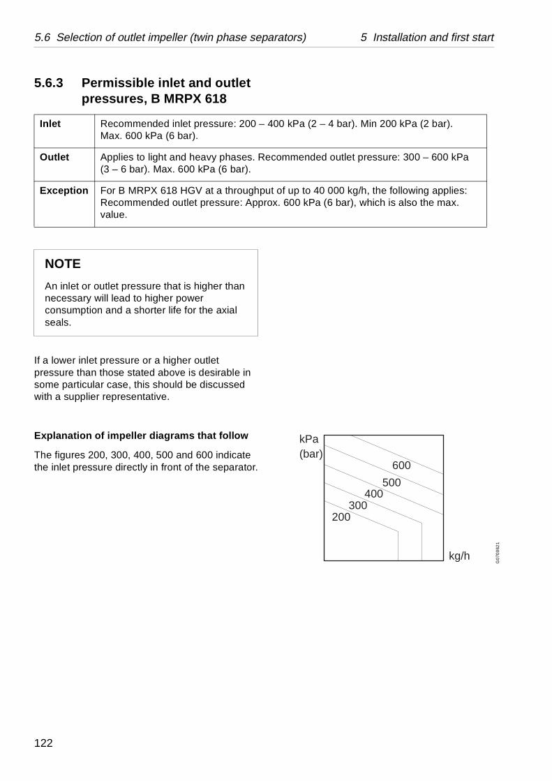
5.6 Selection of outlet impeller (twin phase separators) 5 Installation and first start
400 kPa (2 – 4 bar). Min 200 kPa (2 bar).
commended outlet pressure: 300 – 600 kPa
t of up to 40 000 kg/h, the following applies:ox. 600 kPa (6 bar), which is also the max.
kg/h
kPa(bar)
200300
400500
600
G0
700
621
5.6.3 Permissible inlet and outlet pressures, B MRPX 618
If a lower inlet pressure or a higher outlet pressure than those stated above is desirable in some particular case, this should be discussed with a supplier representative.
Explanation of impeller diagrams that follow
The figures 200, 300, 400, 500 and 600 indicate the inlet pressure directly in front of the separator.
Inlet Recommended inlet pressure: 200 – Max. 600 kPa (6 bar).
Outlet Applies to light and heavy phases. Re(3 – 6 bar). Max. 600 kPa (6 bar).
Exception For B MRPX 618 HGV at a throughpuRecommended outlet pressure: Apprvalue.
NOTE
An inlet or outlet pressure that is higher than necessary will lead to higher power consumption and a shorter life for the axial seals.
122

5 Installation and first start 5.6 Selection of outlet impeller (twin phase separators)
kPa (bar)600(6)
500(5)
400(4)
300(3)
200(2) 10 15 20 25
x 1000 kg/h
200
300
400
500
600
G0
7007
51
Impeller 80 mm diameter heavy phase
The curves that follow have been obtained when operating with water at approx. 25 °C when 3% of the total flow (throughput) was being discharged through the light phase outlet.
Deviations of ± 50 kPa (0,5 bar) from the curves must be regarded as normal.
kPa (bar)600(6)
500(5)
400(4)
300(3)
200(2) 10 15 20 25
x 1000 kg/h
200
300
400
500
600
G0
7007
41
Impeller 120 mm diameter light phase
123

5.6 Selection of outlet impeller (twin phase separators) 5 Installation and first start
400 kPa (2 – 4 bar). Min. 200 kPa (2 bar).
commended outlet pressure: 300 – 600 kPaase: 0 - 700 kPa. Outlet pressure for heavy
t of up to 40 000 kg/h, the following applies: ox. 600 kPa (6 bar), which is also the max.
kg/h
kPa(bar)
200300
400500
600
G07
006
21
5.6.4 Permissible inlet and outlet pressures for C / H MRPX 518 / 618 / 718 and H MRPX 818
If a lower inlet pressure or a higher outlet pressure than those stated above is desirable in some particular case, this should be discussed with a supplier representative.
Explanation of impeller diagrams that follow
The figures 200, 300, 400, 500 and 600 indicate the inlet pressure directly in front of the separator.
kPa (bar) indicates the outlet pressure for the heavy phase. The outlet pressure for the light phase is always higher than the outlet pressure for the heavy phase with the exception of the curves for C MRPX 518 HGV. With nominal throughput for H MRPX 518 HGV (25 000 kg/h) and H MRPX 618 HGV (30 000 kg/h), the outlet pressure for the light phase is approx. 100 kPa (1 bar) higher than the outlet pressure for the heavy phase.
Inlet Recommended inlet pressure: 200 – Max. 600 kPa (6 bar).
Outlet Applies to light and heavy phases. Re(3 – 6 bar). Back pressure for light phphase: 0 - 600 kPa
Exception For H MRPX 618 HGV at a throughpuRecommended outlet pressure: Apprvalue.
NOTE
An inlet or outlet pressure that is higher than necessary will lead to higher power consumption and a shorter life for the axial seals.
124

5 Installation and first start 5.6 Selection of outlet impeller (twin phase separators)
kPa (bar)600(6)
500(5)
400(4)
300(3)
200
10000 20000 30000 kg/h
300
400
500
600
G0
700
821
kPa (bar)600(6)
500(5)
400(4)
300(3)
200(2)
200
10000 20000 30000 kg/h
300
400
500
600
G0
700
921
The curves that follow have been obtained when operating with water at approx. 25 °C when 10% of the total flow (throughput) was being discharged through the light phase outlet.
Deviations of ± 50 kPa (0,5 bar) from the curves must be regarded as normal.
C MRPX 518 HGV
Impeller: 60 mm diameter light phase, 140 mm diameter heavy phase.
Note: This curve shows heavy phase pressure only. Corresponding light phase pressure is given in the curve below.
C MRPX 518 HGV
Impeller: 60 mm diameter light phase, 140 mm diameter heavy phase.
Note: This curve shows light phase pressure only.
125

5.6 Selection of outlet impeller (twin phase separators) 5 Installation and first start
kPa (bar)600(6)
500(5)
400(4)
300(3)
200
10000 20000 30000 kg/h
300
400
500
600
G0
700
821
kPa (bar)600(6)
500(5)
400(4)
300(3)
200
20000 30000 40000kg/h
300
400500
600
G07
011
21
H MRPX 518 HGV
Impeller: 120 mm diameter light phase, 140 mm diameter heavy phase.
This combination of impellers is included in the delivery.
H MRPX 618 HGV
Impeller: 120 mm diameter light phase, 140 mm diameter heavy phase.
This combination of impellers is included in the delivery.
126

5 Installation and first start 5.6 Selection of outlet impeller (twin phase separators)
B
600
500
400
300
200
100
C
200300
400
500600
D
10 20 30 40 50 60 A
G07
010
11
A Flow-rate x 1000 kg/hB Backpressure kPaC Constant inlet pressure, kPaD Minimum inlet pressure to reach flowrate
HMRPX 718 HGV
The curves that follow have been obtained when operating with water at approximately 25 °C when 10% of the total flow (throughput) was being discharged through the light phase outlet.
Deviations ±50 kPa (0,5 bar) from the curves must be regarded as normal.
This combination of impellers is included in the delivery.
Light phase, impeller = Ø 120
Heavy phase, impeller = Ø 140
127

5.6 Selection of outlet impeller (twin phase separators) 5 Installation and first start
ery.
e shadowed area
G0
9847
21
MRPX 818 HGV
The curves that follow have been obtained when operating with water at approximately 25 °C when 10% of the total flow (throughput) was being discharged through the light phase outlet.
Deviations ±50 kPa (0,5 bar) from the curves must be regarded as normal.
Light phase, impeller = Ø 120
Heavy phase, impeller = Ø 140
This combination of impellers is included in the deliv
The separator should normally not be operated in thand preferably in the flow range 30 - 70 m3/h.
Pump diagram for outlet 564481-01
A. Counter-pressureB. Flow“Inl. P” means Inlet pressure
128