Embed Size (px)
Citation preview

Installation Manual
SUBA500 Subwoofer Amplifier

1844·674·[email protected] WWW.ORIGINACOUSTICS.COM
SUBA 500 INSTALLATION MANUAL
Table of Contents
Important Safety Information 1Introduction 3Installing Rack Mount Ears 4Subwoofer Amplifier Controls and Setup 5
FRONT PANEL 5REAR PANEL 6
Connections 8Using line level inputs: 8LCD Display Screens / Functions 9
Control Flow Chart–SUB Mode 13Control Flow Chart–LFE Mode 14Remote Control 15Troubleshooting 16Technical Assistance 17Specifications 18Warranty 20
2-Year Warranty 20Requirements and Warranty Coverage 21Return Process 21
Important Safety Information
The lightning flash with the arrowhead symbol within an equilateral triangle is intended to alert the user to the presence of uninsulated “dangerous voltage” within the product enclosure that may be of sufficient magnitude to constitute a risk of shock to per-sons.
The exclamation point within an equilateral triangle is intended to alert the user to the presence of important operating and maintenance (servicing) instructions in the literature accompanying the product.
CAUTION! DO NOT open the amplifier, attempt any modifications or repairs. There are extremely high voltages present and any servicing must be referred to or an authorized qualified technician.
ATTENTION! Opening the amplifier will void warranty.
WARNING! To prevent shock or fire hazard, never permit moisture or any liquid to get into the amplifier. If an accidental spill occurs, im-mediately shut off the power, unplug its A/C power cord and seek a qualified technician for repair.
CAUTION! To reduce the risk of electric shock, do not remove the cover (or back). No user serviceable parts inside: refer servicing to qualified technician.
All safety instructions should be read before this subwoofer amplifier is operated. Please retain these safety instructions for future reference. Adhere to all warnings on the amplifier and in this manual.
CAUTIONCAUTION: TO REDUCE THE RISK OF ELECTRICAL SHOCK.
DO NOT REMOVE COVER. NO USER SERVICEABLE PARTS INSIDE.
REFER SERVICING TO QUALIFIED SERVICE PERSONNEL.

2 3844·674·[email protected] WWW.ORIGINACOUSTICS.COM
SUBA 500 INSTALLATION MANUAL
Ventilation: The amplifier should be situated so that its location or position does not interfere with its proper ventilation. The amplifier should not be situated on a bed, sofa, rug or similar surface that may block the ventilation openings, nor should it be placed in a built-in installation such as a bookcase or cabinet that may impede the flow of air through the ventilation openings.
Power Source: The amplifier should only be connected to a power supply of the type described in this instruction manual or as marked on the amplifier. Precautions should be taken so that the grounding or polarization means of the amplifier are not defeated.
Power Cords: Power supply cords should be routed so that they are not likely to be walked on or pinched by items placed upon or against them, paying particular attention to wall receptacles and the point where they exit from the amplifier.
Object and Liquid Entry: The amplifier should not be exposed to dripping or splashing and objects filled with liquids, such as vases or plants, should not be placed on top of or next to the amplifier. Care should be taken so that objects do not fall and liquids are not spilled into the enclosure through its ventilation openings.
Damage Requiring Service: This amplifier should be serviced by a qualified technician when:
• The power supply cord has been damaged; or• Objects have fallen or liquid has been spilled into the amplifier; or• The amplifier does not appear to function normally or exhibits a
marked change in performance; or• The amplifier has been dropped or the enclosure is damaged.
Introduction
Congratulations on your purchase of the Subwoofer Amplifier! Your subwoofer amplifier is the result of many years of research and de-velopment dedicated to producing powerful, accurate bass in home audio systems. This manual contains operating procedures and spec-ifications. We recommend you thoroughly read through the material contained in this manual before connecting your amplifier. This will ensure you have an understanding of how to setup and operate your amplifier for optimum performance.
The SUBA500 subwoofer amplifier is a high performance, class D sub-woofer amplifier capable of delivering a minimum of 250W/500W of clean power at 4 ohms. It uses sound processing technology which allows you to tailor the performance of the subwoofer to better match the environment in which it is installed. Both amplifiers feature a large LCD display as well as a turn-and-push controller for DSP configura-tion. On the front panel there are indicators for power and standby, clipping and signal presence.
Your subwoofer amplifier is the result of many years of research and development dedicated to producing powerful, accurate bass in home audio systems. This manual contains operating procedures and spec-ifications. We recommend you thoroughly read through the material contained in this manual before connecting your amplifier. This will ensure you have an understanding of how to setup and operate your amplifier for optimum performance.

4 5844·674·[email protected] WWW.ORIGINACOUSTICS.COM
SUBA 500 INSTALLATION MANUAL
Installing Rack Mount Ears
If you plan to install your sub-woofer amplifier into a standard 19-inch rack, you must install the supplied rack ears.
Using the three screws, attach the supplied rack ears to the sub-woofer amplifier. If required, the 4 feet on the bottom of the ampli-fier can also be removed at this time by unscrewing the mounting screws located in the center of each foot.
Due to the weight of the subwoofer amplifier, it is recommended that rear supports be secured to the rear rack rails. Hardware to do this is not supplied with the amplifier and is specific to the type and depth of rack you are using.
Subwoofer Amplifier Controls and Setup
FRONT PANEL
1. Power Switch: Turns the amplifier on or off. Amplifier must be on for the trigger or auto sense modes to operate.
2. 16 Character x 2-row Liquid Crystal Display: Shows the amplifi-er’s status, menus and settings and works in conjunction with the turn and push navigation controls and the remote control.
3. Programming Navigation Control: Used to scroll through the display menus, change settings and program the DSP controller.
4. Optional Rack Ears: Two rack mount ears are provided for a 19-inch rack mounting.
CAUTION! The subwoofer amplifier is convection cooled and does not use a fan. For this reason, ensure there is adequate ventilation above and below the subwoofer amplifier when rack mounted. Avoid placing heat generating equipment below it in the rack. If the subwoofer amplifier does not receive enough ventilation, it may overheat and switch to standby mode.
6 7844·674·[email protected] WWW.ORIGINACOUSTICS.COM
SUBA 500 INSTALLATION MANUAL
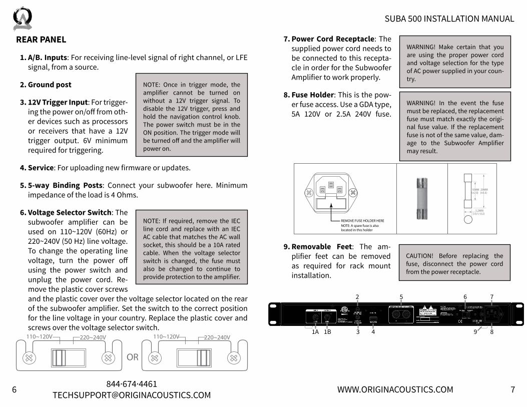
REAR PANEL
1. A/B. Inputs: For receiving line-level signal of right channel, or LFE signal, from a source.
2. Ground post
3. 12V Trigger Input: For trigger-ing the power on/off from oth-er devices such as processors or receivers that have a 12V trigger output. 6V minimum required for triggering.
4. Service: For uploading new firmware or updates.
5. 5-way Binding Posts: Connect your subwoofer here. Minimum impedance of the load is 4 Ohms.
6. Voltage Selector Switch: The subwoofer amplifier can be used on 110~120V (60Hz) or 220~240V (50 Hz) line voltage. To change the operating line voltage, turn the power off using the power switch and unplug the power cord. Re-move the plastic cover screws and the plastic cover over the voltage selector located on the rear of the subwoofer amplifier. Set the switch to the correct position for the line voltage in your country. Replace the plastic cover and screws over the voltage selector switch.
7. Power Cord Receptacle: The supplied power cord needs to be connected to this recepta-cle in order for the Subwoofer Amplifier to work properly.
8. Fuse Holder: This is the pow-er fuse access. Use a GDA type, 5A 120V or 2.5A 240V fuse.
9. Removable Feet: The am-plifier feet can be removed as required for rack mount installation.
NOTE: Once in trigger mode, the amplifier cannot be turned on without a 12V trigger signal. To disable the 12V trigger, press and hold the navigation control knob. The power switch must be in the ON position. The trigger mode will be turned off and the amplifier will power on.
NOTE: If required, remove the IEC line cord and replace with an IEC AC cable that matches the AC wall socket, this should be a 10A rated cable. When the voltage selector switch is changed, the fuse must also be changed to continue to provide protection to the amplifier.
WARNING! Make certain that you are using the proper power cord and voltage selection for the type of AC power supplied in your coun-try.
WARNING! In the event the fuse must be replaced, the replacement fuse must match exactly the origi-nal fuse value. If the replacement fuse is not of the same value, dam-age to the Subwoofer Amplifier may result.
CAUTION! Before replacing the fuse, disconnect the power cord from the power receptacle.
1A 1B
2
3 4
5 6 7
9 8
8 9844·674·[email protected] WWW.ORIGINACOUSTICS.COM
SUBA 500 INSTALLATION MANUAL
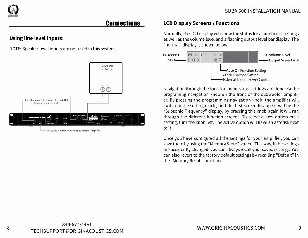
Connections
Using line level inputs:
NOTE: Speaker-level inputs are not used in this system.
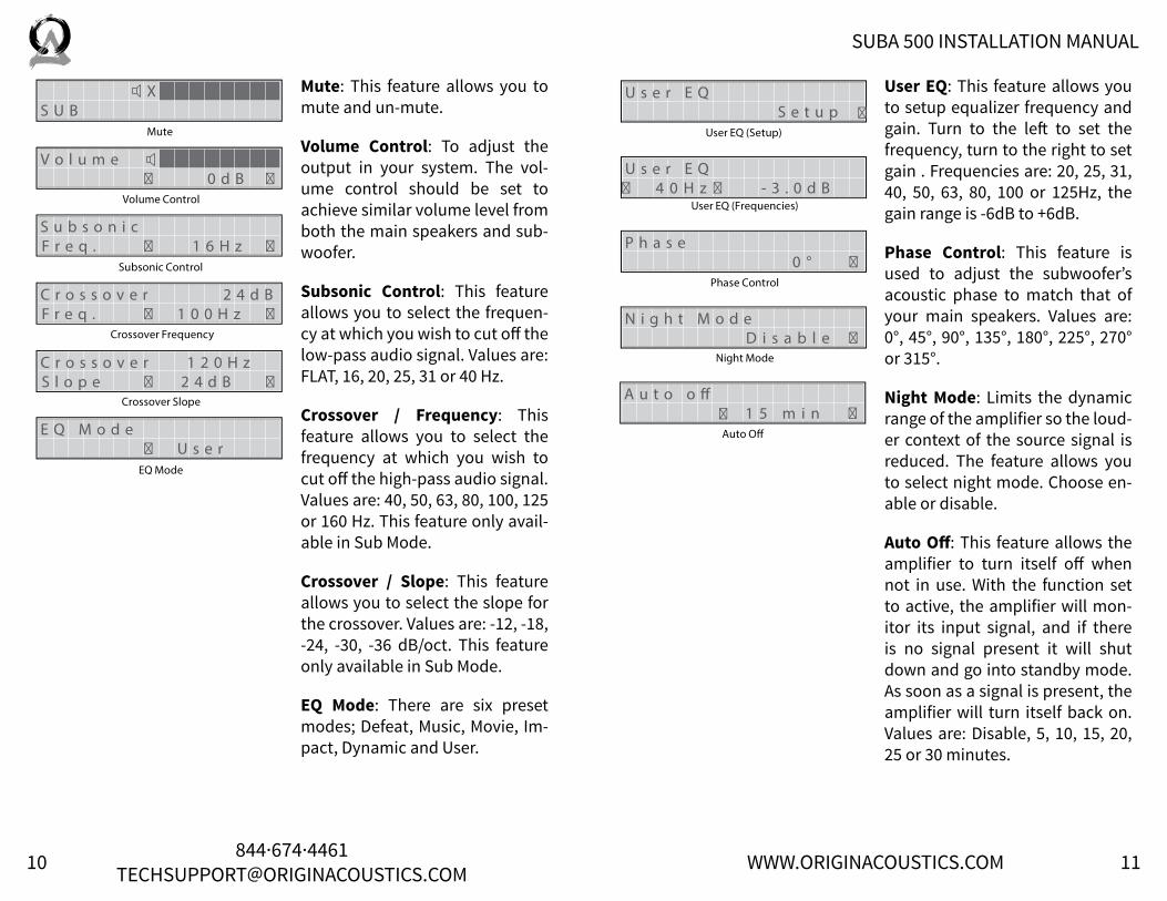
LCD Display Screens / Functions
Normally, the LCD display will show the status for a number of settings as well as the volume level and a flashing output level bar display. The “normal” display is shown below.
Navigation through the function menus and settings are done via the programing navigation knob on the front of the subwoofer amplifi-er. By pressing the programming navigation knob, the amplifier will switch to the setting mode, and the first screen to appear will be the “Subsonic Frequency” display, by pressing this knob again it will run through the different function screens. To select a new option for a setting, turn the knob left. The active option will have an asterisk next to it.
Once you have configured all the settings for your amplifier, you can save them by using the “Memory Store” screen. This way, if the settings are accidently changed, you can always recall your saved settings. You can also revert to the factory default settings by recalling “Default” in the “Memory Recall” function.
10 11844·674·[email protected] WWW.ORIGINACOUSTICS.COM
SUBA 500 INSTALLATION MANUAL
Mute: This feature allows you to mute and un-mute.
Volume Control: To adjust the output in your system. The vol-ume control should be set to achieve similar volume level from both the main speakers and sub-woofer.
Subsonic Control: This feature allows you to select the frequen-cy at which you wish to cut off the low-pass audio signal. Values are: FLAT, 16, 20, 25, 31 or 40 Hz.
Crossover / Frequency: This feature allows you to select the frequency at which you wish to cut off the high-pass audio signal. Values are: 40, 50, 63, 80, 100, 125 or 160 Hz. This feature only avail-able in Sub Mode.
Crossover / Slope: This feature allows you to select the slope for the crossover. Values are: -12, -18, -24, -30, -36 dB/oct. This feature only available in Sub Mode.
EQ Mode: There are six preset modes; Defeat, Music, Movie, Im-pact, Dynamic and User.
User EQ: This feature allows you to setup equalizer frequency and gain. Turn to the left to set the frequency, turn to the right to set gain . Frequencies are: 20, 25, 31, 40, 50, 63, 80, 100 or 125Hz, the gain range is -6dB to +6dB.
Phase Control: This feature is used to adjust the subwoofer’s acoustic phase to match that of your main speakers. Values are: 0°, 45°, 90°, 135°, 180°, 225°, 270° or 315°.
Night Mode: Limits the dynamic range of the amplifier so the loud-er context of the source signal is reduced. The feature allows you to select night mode. Choose en-able or disable.
Auto Off: This feature allows the amplifier to turn itself off when not in use. With the function set to active, the amplifier will mon-itor its input signal, and if there is no signal present it will shut down and go into standby mode. As soon as a signal is present, the amplifier will turn itself back on. Values are: Disable, 5, 10, 15, 20, 25 or 30 minutes.

12 13844·674·[email protected] WWW.ORIGINACOUSTICS.COM
SUBA 500 INSTALLATION MANUAL
Control Flow Chart–SUB ModeMode Select: This feature allows you to select a mode. Set values contain: SUB or LFE (refer to flow charts on pages 8-9).
External Trigger: This feature allows you to select the enable external trigger function. Press and hold the Navigation control knob with the power switch in the ON position to change.
Lock Setting: When this function is active, all settings will be pro-tected until disabled.
Values are: Disable or Enable.
Memory Store: This feature al-lows you to select the memory bank. There are three memory banks, consisting of Mem1, Mem2 and Mem3.
Memory Recall: The feature allows you to recall settings saved using the “Memory Store” function. There are four memory banks total, consisting of Mem1, Mem2, Mem3 and Default. Default resets to factory default settings.

14 15844·674·[email protected] WWW.ORIGINACOUSTICS.COM
SUBA 500 INSTALLATION MANUAL
Remote Control
The remote control duplicates the functions of the programming navi-gation control knob on the front of the subwoofer amplifier, plus adds some additional functions such as power on/off, mute on/off, and one button selection of the six EQs. In a typical home theater installation however, the remote will most likely NOT be used, as the subwoofer amplifier will be configured to a specific subwoofer and room place-ment, and controlled by the main processor or receiver.
USER
DEFEAT
MUTEPOWER
DOWN
ENTERMENU
UP
LEFTVOL -
RIGHTVOL +
EXIT
MUSIC
STORE
IMPACT
RECALL
MOVIE DYNAMIC
Power on/off button
Scroll up button
Volume down button(DSP left-right when
Menu button pressed)
Scroll down button
Select “User” EQ setting button(sub mode only)
Exit navigation mode button
Mute button
Menu button
Volume up button(DSP left-right when Menu button pressed)
Six Preset EQ Modes
Memory recall button
Memory store button
Control Flow Chart–LFE Mode
16 17844·674·[email protected] WWW.ORIGINACOUSTICS.COM
SUBA 500 INSTALLATION MANUAL
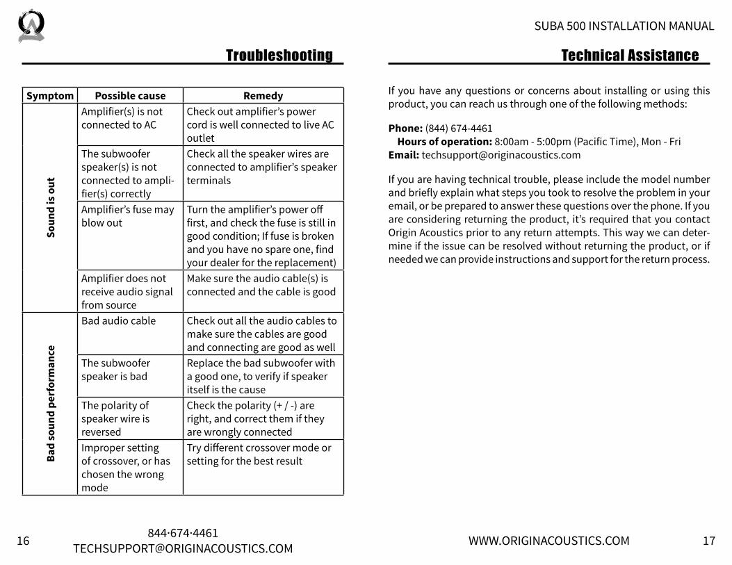
If you have any questions or concerns about installing or using this product, you can reach us through one of the following methods:
Phone: (844) 674-4461 Hours of operation: 8:00am - 5:00pm (Pacific Time), Mon - FriEmail: [email protected]
If you are having technical trouble, please include the model number and briefly explain what steps you took to resolve the problem in your email, or be prepared to answer these questions over the phone. If you are considering returning the product, it’s required that you contact Origin Acoustics prior to any return attempts. This way we can deter-mine if the issue can be resolved without returning the product, or if needed we can provide instructions and support for the return process.
Symptom Possible cause Remedy
Soun
d is
out
Amplifier(s) is not connected to AC
Check out amplifier’s power cord is well connected to live AC outlet
The subwoofer speaker(s) is not connected to ampli-fier(s) correctly
Check all the speaker wires are connected to amplifier’s speaker terminals
Amplifier’s fuse may blow out
Turn the amplifier’s power off first, and check the fuse is still in good condition; If fuse is broken and you have no spare one, find your dealer for the replacement)
Amplifier does not receive audio signal from source
Make sure the audio cable(s) is connected and the cable is good
Bad
soun
d pe
rfor
man
ce
Bad audio cable Check out all the audio cables to make sure the cables are good and connecting are good as well
The subwoofer speaker is bad
Replace the bad subwoofer with a good one, to verify if speaker itself is the cause
The polarity of speaker wire is reversed
Check the polarity (+ / -) are right, and correct them if they are wrongly connected
Improper setting of crossover, or has chosen the wrong mode
Try different crossover mode or setting for the best result
Technical AssistanceTroubleshooting

18 19844·674·[email protected] WWW.ORIGINACOUSTICS.COM
SUBA 500 INSTALLATION MANUAL
SpecificationsModel name SUBA500Part number AMPSUB1X500Type of amplifier High efficient class D;Type of power supply High dynamic toroidal transformerMaximum output power 500w (RMS @ 4Ω)Total harmonic distortion (THD) < 1%Customized presets of mode up to 4 modesEqualization 10 bands / adjustable (-6 to +6 dB)Adjustable crossover 40 to 160 Hz; increment of 1 HzSlope of crossover 12 to 36 dB / OctaveLine-in sensitivity 190 mVPhase control 0 to 315° / 45° per incrementAudio-trigger sensitivity 3 mV at 50 HzAuto-off delay time 5 to 30 minutes (adjustable)External trigger DC 12VThermal protection function yesNight mode (auto-level-compress) yesRemote control IR; handset providedFirmware upgrade USB / type BWeight 16 Lb / 7.3 KgRack-mount hole Horizontal line : 18.3” / 465mm
Vertical line : 1.18” / 30mmDimension (w/o rack-mount) Width: 17.12” / 435mm
Height: 1.75” / 45mmDepth: 10.38” / 264mm
Dimension (with rack-mount) Width: 19.00” / 483mmHeight: 1.75” / 45mmDepth: 10.38” / 264mm
Fuse AC 120V: 5AAC 240V: 2.5A
20 21844·674·[email protected] WWW.ORIGINACOUSTICS.COM
SUBA 500 INSTALLATION MANUAL
This warranty may not be valid if the product was purchased through an unauthorized dealer. This warranty only applies to the individual that made the original purchase, and it cannot be applied to other pur-chases. The purchaser must be prepared to provide proof of purchase (receipt). This warranty will not be valid if the identifying number or serial number has been removed, defaced, or altered.
This warranty does not cover the following:
• Accidental damage• Damage caused by abuse or misuse • Damage caused by attempted repairs/modifications by anyone
other than Origin Acoustics or an authorized dealer • Damage caused by improper installation • Normal wear, maintenance, and environmental issues• Damage caused by voltage inputs in excess of the rated maximum
of the unit• Damage inflicted during the return shipment
Origin Acoustics warrants to the original retail purchaser only that this Origin Acoustics product will be free from defects in materials and workmanship, provided the speaker was purchased from an Origin Acoustics authorized dealer.
If the product is determined to be defective, it will be repaired or re-placed at Origin Acoustics’ discretion. If the product must be replaced yet it is no longer manufactured, it will be replaced with a model of equal to or greater value that is the most similar to the original. If this is the case, installing the replacement model may require mounting modifications; Origin Acoustics will not be responsible for any such related costs.
Before making any return attempts, it is required that you first contact Origin Acoustics. Return product to Origin Acoustics or your dealer, ei-ther in person or by mail. It’s preferable if the product is returned in the original packaging. If this isn’t possible, the customer is responsible for insuring the shipment for the full value of the product.
This warranty is in lieu of all other expressed or implied warranties. Some states do not allow limitations on implied warranties, so this may not apply depending on the customer’s location. (For more information, see Magnuson-Moss Warranty Act.)
Return Process
Requirements and Warranty Coverage
2-Year Warranty
Warranty

©2014 Origin Acoustics. All copyrighted, trademarked and patented elements mentioned herein are the sole property of
Origin Acoustics.