Embed Size (px)
Citation preview
Installation ManualMontageanleitungInstructions de montageIstruzioni per il montaggio
2
D54
386-
001
© 0
4-20
12
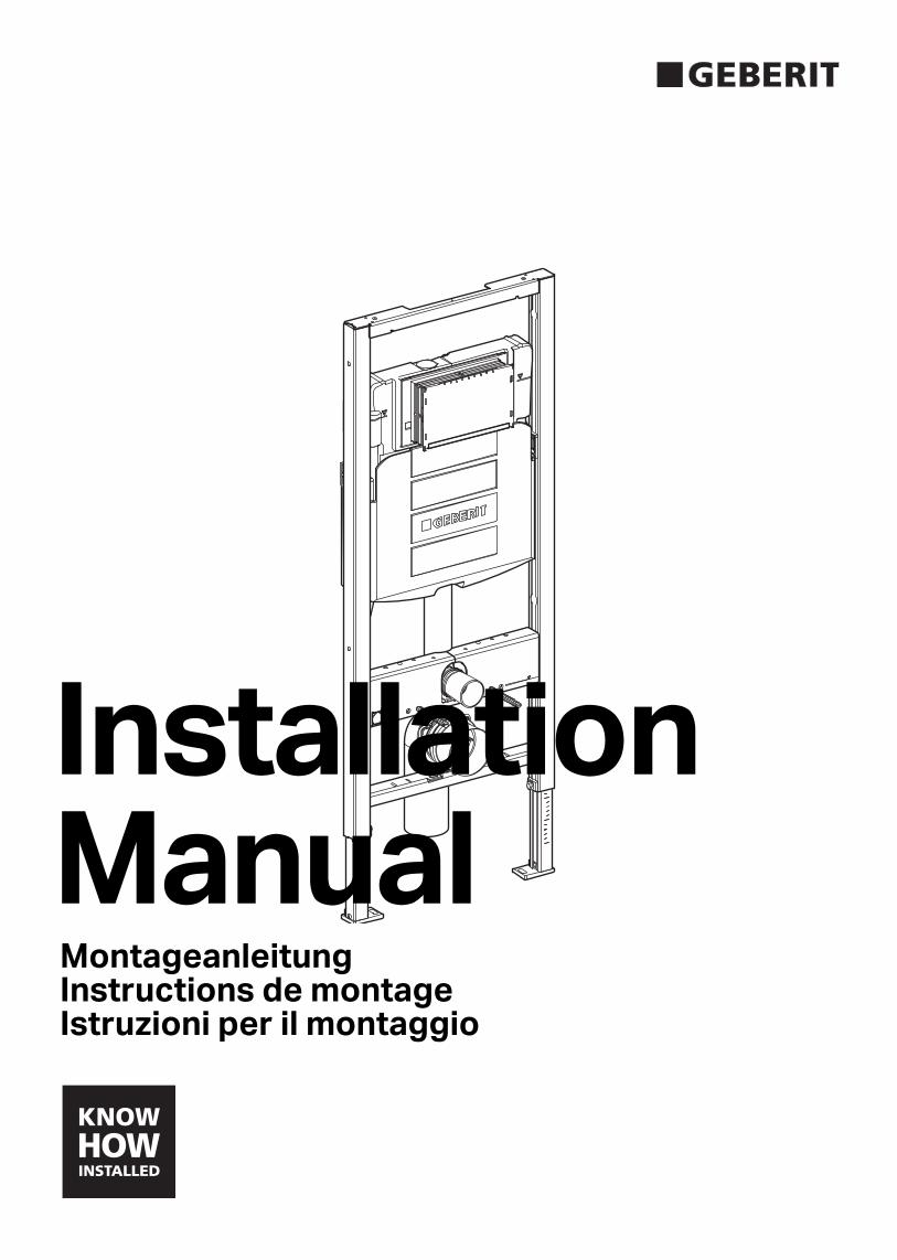
Product SpecificationsGeberit Model No. 111.335.00.5Concealed tank and bowl carrier, wall-hung two-hole toilet bowl and actuator plate.Tank and carrier system shall fit within a minimum 6 3/4" (170) deep wall with studs placed 19 3/4" (500) apart, water supply shall be 1/2" copper, minimum water pressure 35 PSI. The bowl shall be an IAMPO listed 1.6 gallon (6 l) per flush wall-hung bowl.The carrier shall have adjustable height for 15" (381) to 19" (483) bowl rim height. Actuator plates shall be die-cast zinc, plastic or stainless steel and plated to preserve the material’s integrity.
Features• Square structural 16 gauge powder coated steel frame• Water consumption: Dual flush system allows for
0.8 GPF (3 l) or 1.6 GPF (6 l)• Actuator dimension: 9 5/8" (254) width
6 1/2" (165) height• Carrier height adjustable range 15" (381) to 19" (483)
bowl rim height• Impact resistant high density polyethylene tank HDPE• Insulated to prevent condensation• Anti-siphon fill valve meets ANSI / ASSE 1002-99
standard
WarrantyLimited lifetime warranty on tank and carrier.10 year warranty on fill valve and flush valve.One year warranty on actuator plate.
Product Data
FF
3" (75)4" (100)
X
53/16"(135)
71/16"(180)
Material DeterminationRecommended material for wall surface construction:• Gypsum / green board• Cement board• Tile backer board• Ceramic tile surface
Options
Wall thickness not to exceed 3"
71/8"–9"(180–230)
193/4"(500)
X12"–16"
(305–407)
263/8"(670)
47"–51"(1195–1297)
min 4"(100)
4"(100)
43/4"(120)
23/8"(60)
1/2"
22"(558)
Stud FrontCenter Pipe
FRH
FF
Finishd Rim Height (FRH)FRH = X plus 3"
31/2"–53/16"(90–135)
NPT
Vertical discharge elbow 3" DWV standard - Horizontal left: 366.914.16.1 - Horizontal right: 366.913.16.1
Sigma01 Dual flush actuator; white 115.770.11.5 Sigma01 Dual flush actuator; chrome 115.770.21.5
Rumba Single flush actuator; white 115.750.11.1 Rumba Single flush actuator; chrome 115.750.21.1
Tango Single flush actuator; chrome 115.760.21.1
Sigma10 Single flush actuator; withe 115.758.KL.1
Sigma20 Dual flush actuator; white 115.778.KH.1
Sigma50 Dual flush actuator; white 115.788.11.1
Rumba
Sigma01
Tango
Sigma10
Sigma20
Sigma50
3
D54
386-
001
© 0
4-20
12
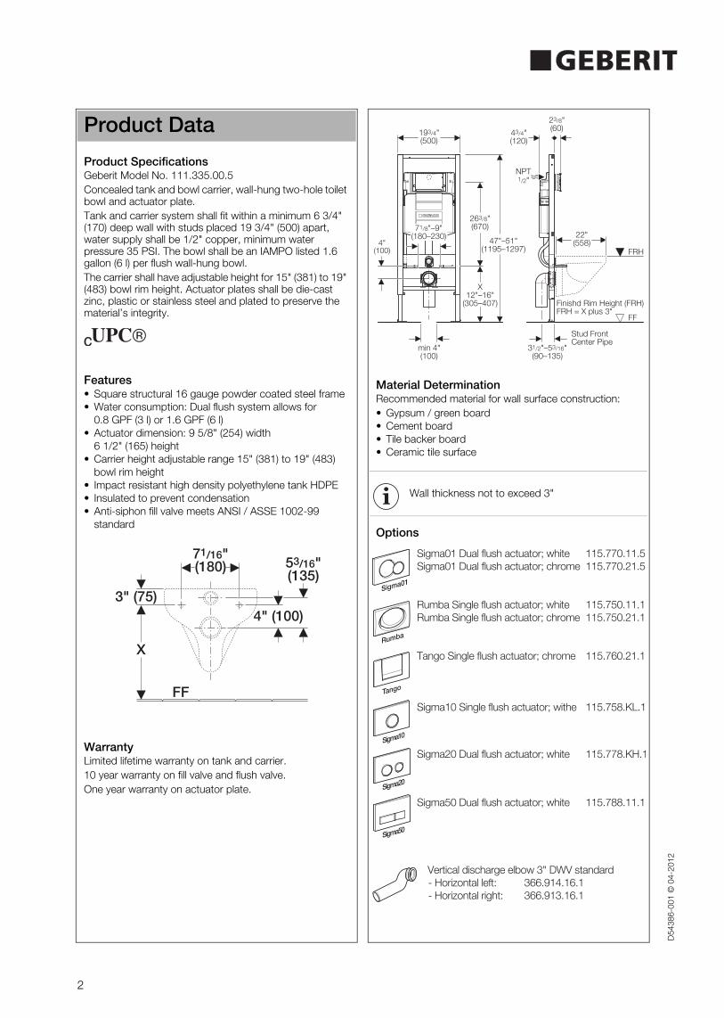
Installation Requirements
Bowl Finished Rim Height (FRH)
Installation
To install tank and carrier, a 2 x 6" wood frame or metal frame construction is required. Studs must be placed 19 3/4" apart (clearance) where carrier will be positioned inside the wall.
Remove carrier and installation hardware from its box. Determine FRH for wall-hung bowl and adjust carrier height in accordance with requirement. Dimensions can be taken from bowl or carrier specification sheet. Be sure to allow for finished floor and sole plate height.
Discharge elbow installation
1
31/2"-43/4"(90-120)
41/8"-53/16"(105-135)
31/2"-43/4"(90-120)
41/8"-53/16"(105-135)
41/8"-53/16"(105-135)
2
3
4
A B
C D
E F
4
D54
386-
001
© 0
4-20
12
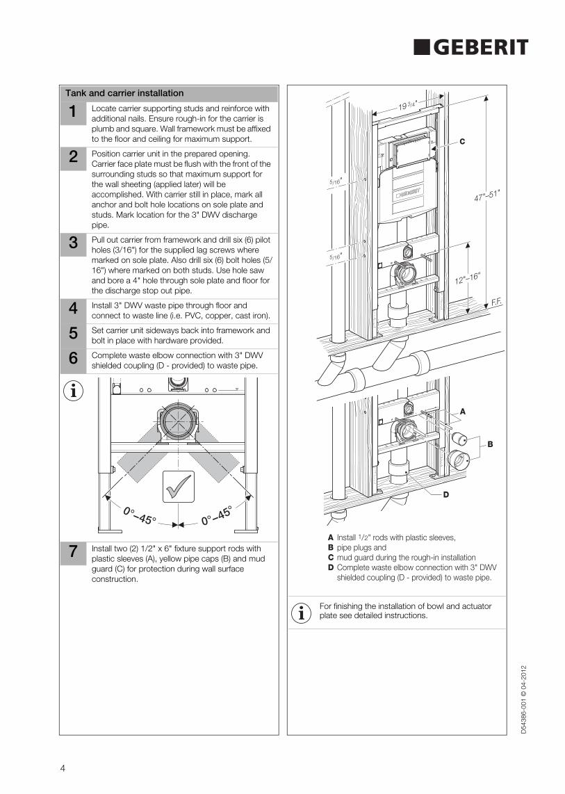
Tank and carrier installation
1 Locate carrier supporting studs and reinforce with additional nails. Ensure rough-in for the carrier is plumb and square. Wall framework must be affixed to the floor and ceiling for maximum support.
2 Position carrier unit in the prepared opening. Carrier face plate must be flush with the front of the surrounding studs so that maximum support for the wall sheeting (applied later) will be accomplished. With carrier still in place, mark all anchor and bolt hole locations on sole plate and studs. Mark location for the 3" DWV discharge pipe.
3 Pull out carrier from framework and drill six (6) pilot holes (3/16") for the supplied lag screws where marked on sole plate. Also drill six (6) bolt holes (5/16") where marked on both studs. Use hole saw and bore a 4" hole through sole plate and floor for the discharge stop out pipe.
4 Install 3" DWV waste pipe through floor and connect to waste line (i.e. PVC, copper, cast iron).
5 Set carrier unit sideways back into framework and bolt in place with hardware provided.
6 Complete waste elbow connection with 3" DWV shielded coupling (D - provided) to waste pipe.
7 Install two (2) 1/2" x 6" fixture support rods with plastic sleeves (A), yellow pipe caps (B) and mud guard (C) for protection during wall surface construction.
0°−45°0°−45°
For finishing the installation of bowl and actuator plate see detailed instructions.
19 3/4"
12"–16"
F.F.
47"–51"
C
A
B
D
5/16"
5/16"
A Install 1/2" rods with plastic sleeves,B pipe plugs andC mud guard during the rough-in installationD Complete waste elbow connection with 3" DWV shielded coupling (D - provided) to waste pipe.
5
D54
386-
001
© 0
4-20
12
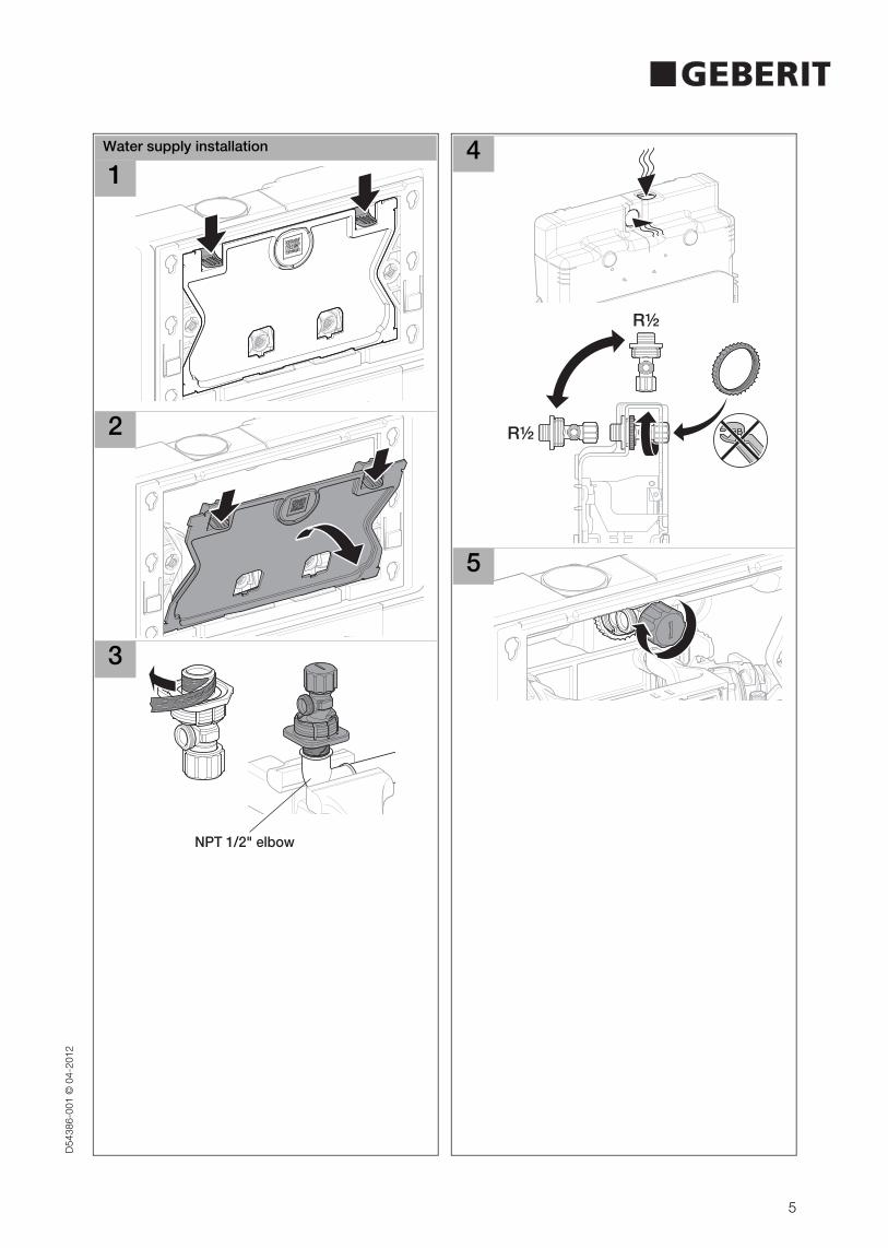
Water supply installation
1
2
3
NPT 1/2" elbow
4
5
R½
R½
6
D54
386-
001
© 0
4-20
12
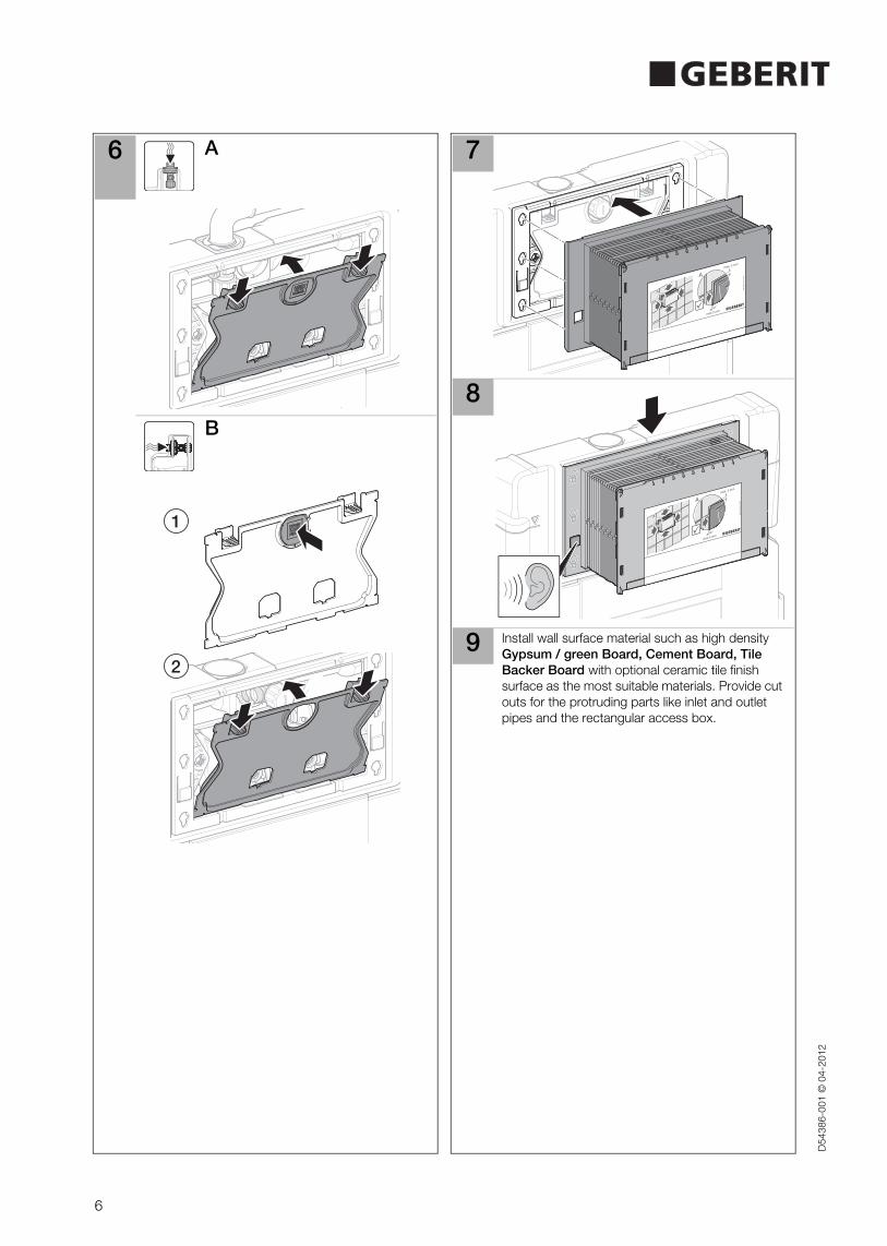
6 A
B
1
2
7
8
9 Install wall surface material such as high density Gypsum / green Board, Cement Board, Tile Backer Board with optional ceramic tile finish surface as the most suitable materials. Provide cut outs for the protruding parts like inlet and outlet pipes and the rectangular access box.
7
D54
386-
001
© 0
4-20
12
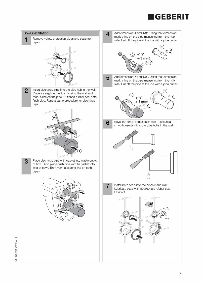
Bowl installation
1 Remove yellow protection plugs and seals from pipes.
2 Insert discharge pipe into the pipe hub in the wall. Place a straight edge flush against the wall and mark a line on the pipe. Fit finned rubber seal onto flush pipe. Repeat same procedure for discharge pipe.
3 Place discharge pipe with gasket into waste outlet of bowl. Also place flush pipe with fin gasket into inlet of bowl. Then mark a second line on both pipes.
1
1
2
22
2
1
1
2
2
1
1
4 Add dimension X and 1/8". Using that dimension, mark a line on the pipe measuring from the hub side. Cut off the pipe at the line with a pipe cutter.
5 Add dimension Y and 1/8". Using that dimension, mark a line on the pipe measuring from the hub side. Cut off the pipe at the line with a pipe cutter.
6 Bevel the sharp edges as shown to assure a smooth insertion into the pipe hubs in the wall.
7 Install both seals into the pipes in the wall. Lubricate seals with appropriate rubber seal lubricant.
1
2
X
X+1/8"+(3 mm)
Y
+1/8"+(3 mm)
Y
12
8
996.506.00.0 (03)D54386-001 © 04-2012
Geberit International AG, Schachenstrasse 77, CH-8645 [email protected] ➔ www.geberit.com
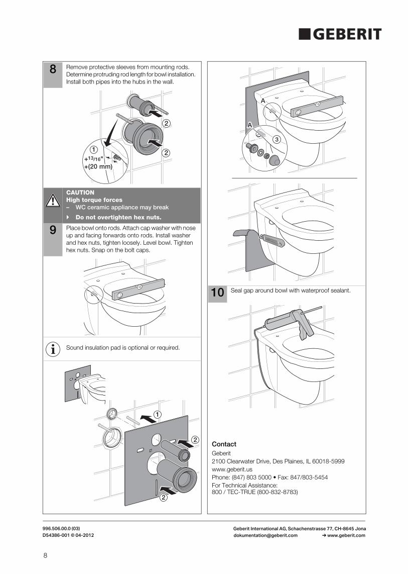
8 Remove protective sleeves from mounting rods. Determine protruding rod length for bowl installation. Install both pipes into the hubs in the wall.
CAUTIONHigh torque forces– WC ceramic appliance may break
Do not overtighten hex nuts.
9 Place bowl onto rods. Attach cap washer with nose up and facing forwards onto rods. Install washer and hex nuts, tighten loosely. Level bowl. Tighten hex nuts. Snap on the bolt caps.
Sound insulation pad is optional or required.
1+13/16"+(20 mm)+13/16"+(20 mm)
2
2
2
1
2
Contact
10 Seal gap around bowl with waterproof sealant.
Geberit2100 Clearwater Drive, Des Plaines, IL 60018-5999www.geberit.usPhone: (847) 803 5000 • Fax: 847/803-5454For Technical Assistance: 800 / TEC-TRUE (800-832-8783)
AA
AA
3