Embed Size (px)
Citation preview

SEELEY INTERNATIONAL BRAEMAR ECO-SUPERSTARSH18, SH25 & WF25 HEATERS
INSTALLATION MANUAL
Employers and Employees Responsibility
The installation and maintenance of gas space heating systems, particularly at height, has the potential to create Occupational Health and Safety issues for those involved. Installers are advised to ensure they are familiar with relevant State and Federal legislation, such as Acts, Regulations, approved Codes of Practice and Australian Standards, which offer practical guidance on these health and safety issues. Compliance with these regulations will require appropriate work practices, equipment, training and qualification of workers. Seeley International provides the following information as a guide to contractors and employees to assist in minimising risk.
Risk Assessment
A risk assessment of all hazardous tasks is required under legislation. A risk assessment is an essential element that should be conducted before the commencement of work, to identify and eliminate the risk of falls and other risks, or to minimise these risks by implementing control measures. This does not need to be a complicated process - it is a matter of assessing the job to be done and considering what actions are necessary so the person doing the job does not injure themselves.
This should be considered in terms of:��What are the chances of an incident occurring?��What could the possible consequences be?��What can be done to reduce, or better still, eliminate the risk?
Some points to consider when working on or in a roof
��What is the best and safest access to the roof and working areas?��What condition is the roof in? Should the roof structure and surface be checked?��Does the worker have appropriate footwear?��Are all power cables/extension leads safe and appropriately rated?��Are all ladders, tools and equipment suitable and in good condition?��Where ladders are to be used, is there a firm, stable base for them to stand on? Can they be tied or secured in some way at the top.��Is there a roof anchor to attach a harness and lanyard to? If so, instruction should be issued for the use of an approved harness or only suitably trained people used.��Are all tools and materials being used, prevented from slipping and falling onto a person at ground level? Is the area below the work area suitably protected to prevent people entering this area. ��Does the work schedule take into account weather conditions, allowing for work to be suspended in high winds, thunder storms/lightning or other types of weather giving wet, slippery surfaces? ��Is there an on-going safety check system of harnesses, ropes, ladders and access/lifting equipment, and where they exist on roofs, anchor points before the commencement of work? ��Is there a system which prevents employees from working on or in roofs if they are unwell or under the influence of drugs or alcohol? ��Are there any special conditions to consider i.e. excessive roof pitch, limited ground area, fragile roof, electrical power lines?
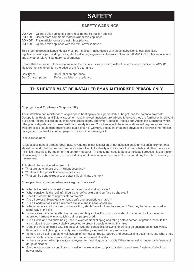
DO NOT Operate this appliance before reading the instruction bookletDO NOT Use or store flammable materials near this appliance.DO NOT Place articles on or against this appliance.DO NOT Operate this appliance with the front cover removed.
This Braemar Ecostar Space Heater must be installed in accordance with these instructions, local gas fitting regulations, municipal building codes, electrical wiring regulations, Australian Standard AS/NZS 5601 Gas Installations and any other relevant statutory requirements.
Ensure that the heater is located to maintain the minimum clearances from the flue terminal as specified in AS5601. Measurement is taken from the edge of the flue terminal.
Gas Type: Refer label on appliance.Gas Consumption: Refer data label on appliance.
SAFETYSAFETY WARNINGS
THIS HEATER MUST BE INSTALLED BY AN AUTHORISED PERSON ONLY
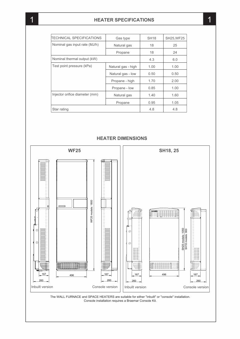
HEATER SPECIFICATIONS1
TECHNICAL SPECIFICATIONS SH25,WF25SH18Gas type
Nominal gas input rate (MJ/h) 2518Natural gas
2418Propane
Nominal thermal output (kW) 6.04.3
Test point pressure (kPa) 1.001.00Natural gas - high
0.500.50Natural gas - low
2.001.70Propane - high
1.000.85Propane - low
Injector orifice diameter (mm) 1.601.40Natural gas
1.050.95Propane
496167
260
SH
25 m
odel
s: 1
050
167
260
SH
18 m
odel
s: 9
00
Inbuilt version Console version
Star rating 4.84.8
The WALL FURNACE and SPACE HEATERS are suitable for either "inbuilt" or "console" installation.Console installation requires a Braemar Console Kit.
1
167
260
496167
260
WF2
5 m
odel
s: 1
800
Inbuilt version Console version
WF25 SH18, 25
HEATER DIMENSIONS
PREPARATION AND CONNECTIONS2 2
HEATER PREPARATION
��Remove the protective plastic film from the front cover and discard.��If the heater is to be installed as a console unit, fit the console cover panels to the front cover at this point. Refer instructions in console kit.��If a rear register is to be installed, fit the relevant components to the heater at this point. Refer instructions in the rear register kit.
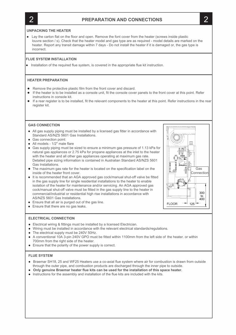
GAS CONNECTION��All gas supply piping must be installed by a licensed gas fitter in accordance with Standard AS/NZS 5601 Gas Installations.��Gas connection point:� All models - 1/2" male flare ��Gas supply piping must be sized to ensure a minimum gas pressure of 1.13 kPa for natural gas appliances or 2.75 kPa for propane appliances at the inlet to the heater with the heater and all other gas appliances operating at maximum gas rate. Detailed pipe sizing information is contained in Australian Standard AS/NZS 5601 Gas Installations.��The maximum gas rate for the heater is located on the specification label on the inside of the heater front cover.��It is recommended that an AGA approved gas cock/manual shut-off valve be fitted in the gas supply line for single residential installations to the heater to enable isolation of the heater for maintenance and/or servicing. An AGA approved gas cock/manual shut-off valve must be fitted in the gas supply line to the heater in commercial/industrial or residential high rise installations in accordance with AS/NZS 5601 Gas Installations.��Ensure that all air is purged out of the gas line.��Ensure that there are no gas leaks.
ELECTRICAL CONNECTION��Electrical wiring & fittings must be installed by a licensed Electrician.��Wiring must be installed in accordance with the relevant electrical standards/regulations. ��The electrical supply must be 240V 50Hz.��A conventional 10A 3-pin 240V GPO must be fitted within 1100mm from the left side of the heater. or within 700mm from the right side of the heater.��Ensure that the polarity of the power supply is correct.
300 to
400125FLOOR
FLUE SYSTEM��Braemar SH18, 25 and WF25 Heaters use a co-axial flue system where air for combustion is drawn from outside through the outer pipe, and combustion products are discharged through the inner pipe to outside.��Only genuine Braemar heater flue kits can be used for the installation of this space heater.��Instructions for the assembly and installation of the flue kits are included with the kits.
GasConnection
UNPACKING THE HEATER��Lay the carton flat on the floor and open. Remove the font cover from the heater (screws inside plastic louvre section / s). Check that the heater model and gas type are as required - model details are marked on the heater. Report any transit damage within 7 days - Do not install the heater if it is damaged or, the gas type is incorrect.
FLUE SYSTEM INSTALLATION��Installation of the required flue system, is covered in the appropriate flue kit instruction.
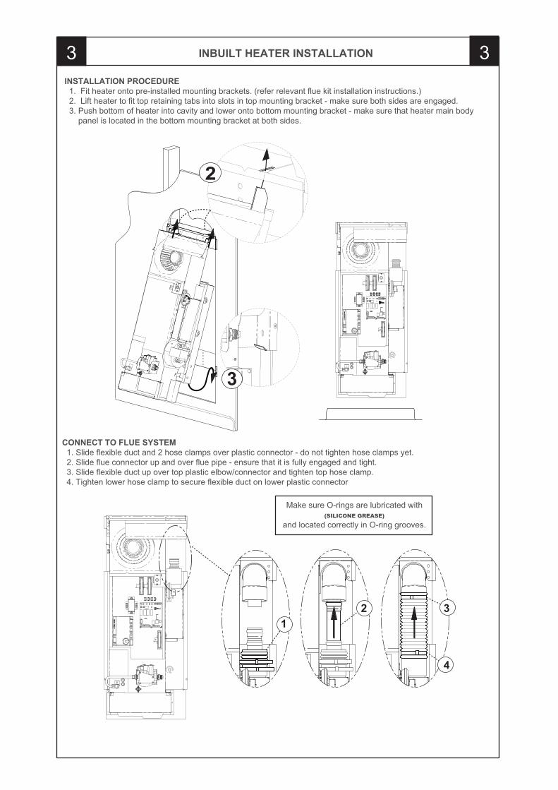
INBUILT HEATER INSTALLATION3 3INSTALLATION PROCEDURE 1. Fit heater onto pre-installed mounting brackets. (refer relevant flue kit installation instructions.) 2. Lift heater to fit top retaining tabs into slots in top mounting bracket - make sure both sides are engaged. 3. Push bottom of heater into cavity and lower onto bottom mounting bracket - make sure that heater main body panel is located in the bottom mounting bracket at both sides.
CONNECT TO FLUE SYSTEM 1. Slide flexible duct and 2 hose clamps over plastic connector - do not tighten hose clamps yet. 2. Slide flue connector up and over flue pipe - ensure that it is fully engaged and tight. 3. Slide flexible duct up over top plastic elbow/connector and tighten top hose clamp. 4. Tighten lower hose clamp to secure flexible duct on lower plastic connector
Make sure O-rings are lubricated with(SILICONE GREASE)
and located correctly in O-ring grooves.
2
3
12 3
4
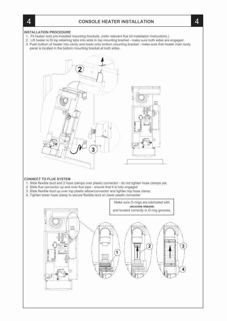
CONSOLE HEATER INSTALLATION4 4
Make sure O-rings are lubricated with(SILICONE GREASE)
and located correctly in O-ring grooves.
3
2
INSTALLATION PROCEDURE 1. Fit heater onto pre-installed mounting brackets. (refer relevant flue kit installation instructions.) 2. Lift heater to fit top retaining tabs into slots in top mounting bracket - make sure both sides are engaged. 3. Push bottom of heater into cavity and lower onto bottom mounting bracket - make sure that heater main body panel is located in the bottom mounting bracket at both sides.
CONNECT TO FLUE SYSTEM 1. Slide flexible duct and 2 hose clamps over plastic connector - do not tighten hose clamps yet. 2. Slide flue connector up and over flue pipe - ensure that it is fully engaged 3. Slide flexible duct up over top plastic elbow/connector and tighten top hose clamp. 4. Tighten lower hose clamp to secure flexible duct on lower plastic connector
12 3
4
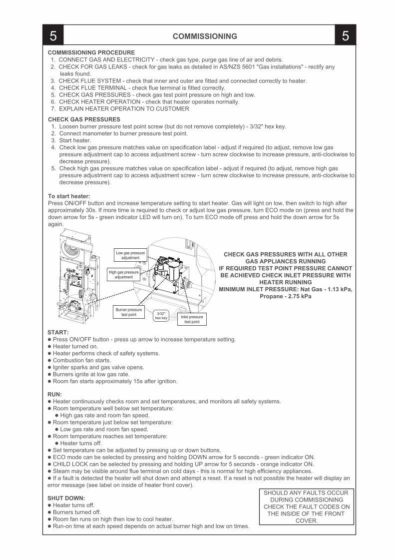
COMMISSIONING5 5COMMISSIONING PROCEDURE 1. CONNECT GAS AND ELECTRICITY - check gas type, purge gas line of air and debris. 2. CHECK FOR GAS LEAKS - check for gas leaks as detailed in AS/NZS 5601 "Gas installations" - rectify any leaks found. 3. CHECK FLUE SYSTEM - check that inner and outer are fitted and connected correctly to heater. 4. CHECK FLUE TERMINAL - check flue terminal is fitted correctly. 5. CHECK GAS PRESSURES - check gas test point pressure on high and low. 6. CHECK HEATER OPERATION - check that heater operates normally. 7. EXPLAIN HEATER OPERATION TO CUSTOMER
CHECK GAS PRESSURES 1. Loosen burner pressure test point screw (but do not remove completely) - 3/32" hex key. 2. Connect manometer to burner pressure test point. 3. Start heater. 4. Check low gas pressure matches value on specification label - adjust if required (to adjust, remove low gas pressure adjustment cap to access adjustment screw - turn screw clockwise to increase pressure, anti-clockwise to decrease pressure). 5. Check high gas pressure matches value on specification label - adjust if required (to adjust, remove high gas pressure adjustment cap to access adjustment screw - turn screw clockwise to increase pressure, anti-clockwise to decrease pressure).
To start heater:Press ON/OFF button and increase temperature setting to start heater. Gas will light on low, then switch to high after approximately 30s. If more time is required to check or adjust low gas pressure, turn ECO mode on (press and hold the down arrow for 5s - green indicator LED will turn on). To turn ECO mode off press and hold the down arrow for 5s again.
C
Burner pressure test point Inlet pressure
test point
High gas pressure adjustment
Low gas pressure adjustment
3/32"hex key
START:� Press ON/OFF button - press up arrow to increase temperature setting.� Heater turned on.� Heater performs check of safety systems.� Combustion fan starts.� Igniter sparks and gas valve opens.� Burners ignite at low gas rate.� Room fan starts approximately 15s after ignition.
RUN:� Heater continuously checks room and set temperatures, and monitors all safety systems.� Room temperature well below set temperature: � High gas rate and room fan speed.� Room temperature just below set temperature: � Low gas rate and room fan speed.� Room temperature reaches set temperature: � Heater turns off.� Set temperature can be adjusted by pressing up or down buttons.� ECO mode can be selected by pressing and holding DOWN arrow for 5 seconds - green indicator ON.� CHILD LOCK can be selected by pressing and holding UP arrow for 5 seconds - orange indicator ON.� Steam may be visible around flue terminal on cold days - this is normal for high efficiency appliances.� If a fault is detected the heater will shut down and attempt a reset. If a reset is not possible the heater will display an error message (see label on inside of heater front cover).
SHUT DOWN:� Heater turns off.� Burners turned off.� Room fan runs on high then low to cool heater.� Run-on time at each speed depends on actual burner high and low on times.
CHECK GAS PRESSURES WITH ALL OTHER GAS APPLIANCES RUNNING
IF REQUIRED TEST POINT PRESSURE CANNOT BE ACHIEVED CHECK INLET PRESSURE WITH
HEATER RUNNINGMINIMUM INLET PRESSURE: Nat Gas - 1.13 kPa,
Propane - 2.75 kPa
SHOULD ANY FAULTS OCCUR DURING COMMISSIONING
CHECK THE FAULT CODES ONTHE INSIDE OF THE FRONT
COVER.
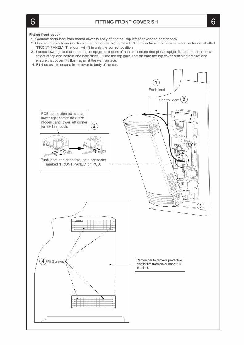
FITTING FRONT COVER SH6 6
Remember to remove protective plastic film from cover once it is installed.
Fitting front cover 1. Connect earth lead from heater cover to body of heater - top left of cover and heater body 2. Connect control loom (multi coloured ribbon cable) to main PCB on electrical mount panel - connection is labelled "FRONT PANEL". The loom will fit in only the correct position 3. Locate lower grille section on outlet spigot at bottom of heater - ensure that plastic spigot fits around sheetmetal spigot at top and bottom and both sides. Guide the top grille section onto the top cover retaining bracket and ensure that cover fits flush against the wall surface. 4. Fit 4 screws to secure front cover to body of heater.
PCB connection point is at lower right corner for SH25 models, and lower left corner for SH18 models.
Push loom end-connector onto connector marked "FRONT PANEL" on PCB.
Earth lead
Control loom
Fit Screws
1
2
2
3
4
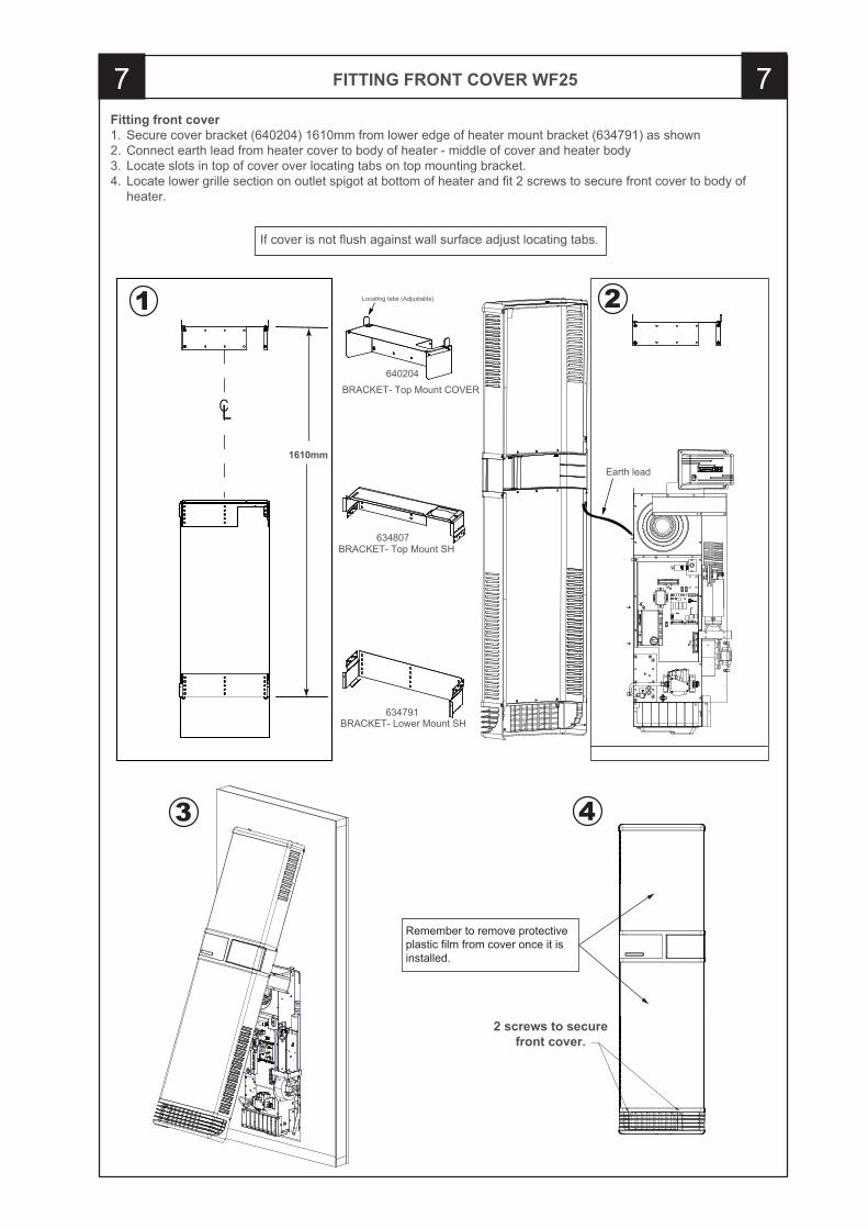
FITTING FRONT COVER WF257 7Fitting front cover1. Secure cover bracket (640204) 1610mm from lower edge of heater mount bracket (634791) as shown2. Connect earth lead from heater cover to body of heater - middle of cover and heater body3. Locate slots in top of cover over locating tabs on top mounting bracket. 4. Locate lower grille section on outlet spigot at bottom of heater and fit 2 screws to secure front cover to body of heater.
If cover is not flush against wall surface adjust locating tabs.
Earth lead
Locating tabs (Adjustable)
BRACKET- Top Mount COVER640204
BRACKET- Top Mount SH634807
BRACKET- Lower Mount SH634791
1610mm
CL
1 2
3
Remember to remove protective plastic film from cover once it is installed.
2 screws to securefront cover.
4
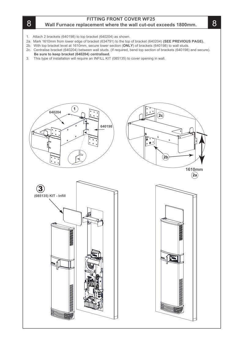
FITTING FRONT COVER WF25Wall Furnace replacement where the wall cut-out exceeds 1800mm. 8 8
1. Attach 2 brackets (640198) to top bracket (640204) as shown.2a. Mark 1610mm from lower edge of bracket (634791) to the top of bracket (640204) (SEE PREVIOUS PAGE).2b. With top bracket level at 1610mm, secure lower section (ONLY) of brackets (640198) to wall studs.2c. Centralise bracket (640204) between wall studs. (If required, bend top section of brackets (640198) and secure). Be sure to keep bracket (640204) centralised.3. This type of installation will require an INFILL KIT (085135) to cover opening in wall.
2a
2b
2c
1610mm
1
640198
640204
3(085135) KIT - Infill
EXPLAIN OPERATION TO CUSTOMER 9
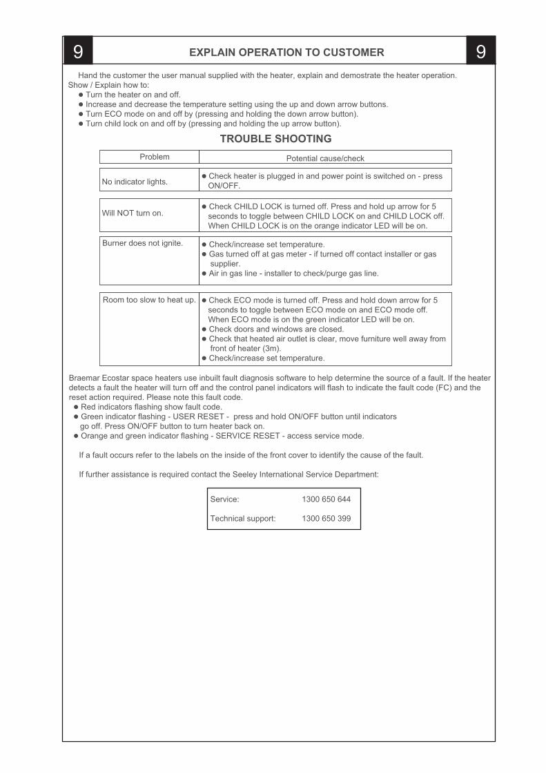
No indicator lights.
Will NOT turn on.
Burner does not ignite.
Room too slow to heat up.
Problem
Hand the customer the user manual supplied with the heater, explain and demostrate the heater operation.Show / Explain how to:� � Turn the heater on and off.� � Increase and decrease the temperature setting using the up and down arrow buttons.� � Turn ECO mode on and off by (pressing and holding the down arrow button).� � Turn child lock on and off by (pressing and holding the up arrow button).
Potential cause/check
� Check heater is plugged in and power point is switched on - press ON/OFF.
� Check CHILD LOCK is turned off. Press and hold up arrow for 5 seconds to toggle between CHILD LOCK on and CHILD LOCK off. When CHILD LOCK is on the orange indicator LED will be on.
� Check/increase set temperature.� Gas turned off at gas meter - if turned off contact installer or gas supplier.� Air in gas line - installer to check/purge gas line.
� Check ECO mode is turned off. Press and hold down arrow for 5 seconds to toggle between ECO mode on and ECO mode off. When ECO mode is on the green indicator LED will be on.� Check doors and windows are closed.� Check that heated air outlet is clear, move furniture well away from front of heater (3m).� Check/increase set temperature.
Braemar Ecostar space heaters use inbuilt fault diagnosis software to help determine the source of a fault. If the heater detects a fault the heater will turn off and the control panel indicators will flash to indicate the fault code (FC) and the reset action required. Please note this fault code. � Red indicators flashing show fault code. � Green indicator flashing - USER RESET - press and hold ON/OFF button until indicators go off. Press ON/OFF button to turn heater back on. � Orange and green indicator flashing - SERVICE RESET - access service mode.
If a fault occurs refer to the labels on the inside of the front cover to identify the cause of the fault.
If further assistance is required contact the Seeley International Service Department:
Service: 1300 650 644
Technical support: 1300 650 399
TROUBLE SHOOTING
9
634166c
Warranty ServiceAustralia 1-300-650-644seeleyinternational.com
It is the policy of Seeley International to introduce continual product improvement. Accordingly, specifications are subject to
change without notice. Please consult with your dealer to confirm the specifications of the model selected.