Embed Size (px)
Citation preview

800-603-5464king-electric.com
INSTALLATION
MANUAL This installation manual includes factory guidelines for installing King Electric floor heating systems. These guidelines must be followed to ensure warranty coverage. Contact King Electric for any questions regarding proper installation of the heating cable.
IMPORTANT: Save these instructions!
Electric Floor Heating Mat Systems
mat series

King Electrical Floor Heating Mat Installation Manual 2
Electric Floor Heating Cable Systems
www.king-electric.com
Table of Contents
1.
2.
3.
4.
5.
General Information ---------------------------------------------------------------
Typical Installations -----------------------------------------------------------------
3
3
4
5
6 Cable Test Log ---------------------------------------------------------------------
6. STEP 2: Layout Planning and Product Selection --------------------------------- 7
7. 120 Volt Selection Table ----------------------------------------------------------- 9
8. 240 Volt Selection Table -------------------------------------------------------------- 9
9. STEP 3: Thermostat Location -------------------------------------------------------- 10
10. Materials Required ------------------------------------------------------------------ 11
11. STEP 4: Electrical Rough-in New Construction ------------------------------- 12
12. STEP 4R: Electrical Rough-in for Remodel ------------------------------------ 13
13. STEP 5: Installing the Cold Lead ---------------------------------------------------- 14
14. STEP 6 : Installing the Mat ----------------------------------------------------------- 16
15. STEP 7: Install the Floor Sensor ------------------------------------------------------ 18
16. STEP 8: Apply Scratch Coat --------------------------------------------------------- 18
17. STEP 9: Install the Thermostat ---------------------------------------------------- 19
20
STEP 1: Inspect and Testing the Cable and Floor Sensor______________
Important Safeguards and Warnings ______________________________
Cable Test Log________________________________________________
18. Troubleshooting_______________________________________________
King Electrical Floor Heating Mat Installation Manual 3
General information
Electric floor heating is a simple, economical way to warm any floor providing years of lasting comfort whether it is used as supplemental or the primary heating source. This installation manual provides guidelines, safety warnings and describes the
elements of properly installing the King Electric floor heating system which are:
1. How to design the proper layout for the room.
2. How to select the right product for the application.
3. How to properly install the system.
This installation manual DOES NOT provide detailed information regarding thermostat installation. It is important to thoroughly review
the thermostat installation manual included with the thermostat. For additional information regarding any aspect of the King Electric floor heating system, please contact us at:
King Electrical Manufacturing Co. 9131 10th Ave South
Seattle, WA 98108
1-800-603-5464 www.king-electric.com
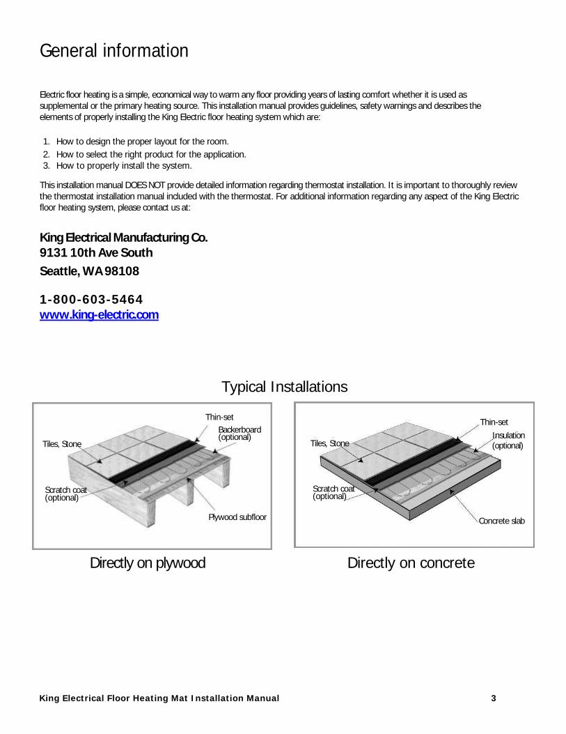
Typical Installations
Directly on plywood Directly on concrete
Tiles, Stone
Scratch coat (optional)
Thin-set
Plywood subfloor
Backerboard (optional)
Tiles, Stone
Scratch coat (optional)
Concrete slab
Thin-set
(optional) Insulation

King Electrical Floor Heating Mat Installation Manual 4
Important Safeguards and Warnings READ AND FOLLOW THE WARNINGS AND INSTALLATION INSTRUCTIONS PROVIDED IN THIS MANUAL. FAILURE TO DO SO COULD RESULT IN ANY OF THE FOLLOWING: CABLE FAILURE, IMPROPER SYSTEM OPERATION, PROPERTY DAMAGE, BODILY INJURY OR DEATH. THE WARRANTY IS INVALID IF THE WARNINGS AND SPECIFIC INSTRUCTIONS ARE NOT FOLLOWED.
WARNING: ELECTRIC SHOCK AND FIRE HAZARD!
1. The instruction manual follows North American standard building construction conventions.
2. An electrical inspector may be required before, during and after the installation. It is recommended to contact your local building department BEFORE beginning the installation.
3. DO NOT energize the mat before installation as it will cause overheating or damage to the cable.
4. Connect mats to rated voltage only. Be sure to size for conductors properly to carry the rated amperage. 5. This product is approved for indoor use only. Minimum installation temperature is 40 F .
6. Use only copper supply wires. Be sure to size for conductors properly to carry the rated amperage. 7. DO NOT cut the blue heating cable or attempt to alter the length in any way. The black cold lead can
be shortened, but only at the end of the cable where the power leads are exposed. DO NOT cut at the splice between the cold lead (black wire) and the heating wire. (blue wire)
8. DO NOT install heating cable under any type of floor that requires nailing.
9. Ground fault protection (GFCI) is required when installed in wet environments such as a bathroom. Consult the local electrical and building authority to determine and additional requirements in your area.
10. If the GFCI trips during normal conditions and cannot be reset, consult an electrician for service. NEVER attempt to bypass or disable the GFCI system.
11. When installing cable in shower areas, the cable must be installed under the waterproofing membrane to
keep the cables dry. 12. DO NOT drill, nail of cut into any floors that have heating cable installed underneath. This could result in
contact with live electrical wires causing electrical shock.
13. DO NOT use staples, nails or similar fasteners directly on the cable. Use only factory the factory
recommended system to attach the mat. The use of any other fastening method will void the warranty. 14. Use a smooth plastic trowel only. NEVER bang or drop a tool on the cable. Care should be taken not to
nick or gouge cable.
15. DO NOT install the heating cable under a cabinet or other built-in. This will cause the cable to overheat. 16. DO NOT install the heating cable (blue wire) inside a wall. Only the cold lead can go into a wall stud.
17. DO NOT extend the heating cable beyond the room or area that it originates. 18. DO NOT attempt to repair damaged cable without a factory splice kit.
19. DO NOT overlap heating cables. Dangerous overheating will occur.
20. DO NOT allow the cold lead or thermostat sensor to cross or overlap the heating cable.
21. All cables must be completely embedded into a cement based mortar including the cold lead, cold lead
splice, heating cable, heating cable tail splice and thermostat sensor with the wire lead. 22. DO NOT bend the cable at sharp right angles. Always maintain a minimum 1” radius.
23. Maintain at least a minimum of 2” between heating cables.
24. Test and record the cable resistance at least 4 times during installation. 25. After installation of the cable, the installer must inspect and remove damaged or defective cables
before they are covered or concealed.
26. The installer should mark the appropriate circuit breaker reference label indicating which branch circuit
supplies the circuits to those electric space heating cables. 27. These products are to be installed in accordance with ANSI/NFPA 70, National Electrical Code (NEC) and
CAN/CSA-C22.1, Canadian Electrical Code, Part I (CEC).
28. Only UL Listed conduit, fittings, and/or other components are to be used. 29. Products are listed for installations with a maximum thermal resistance value of R-1 for floor covering that
can be placed on top of your product

King Electrical Floor Heating Mat Installation Manual 5
STEP 1: Inspecting and testing the cable and floor sensor
1.1 Take the mat out of the box and inspect it for any physical damage.
1.2 Test the insulation and the resistance of the cable and record data in the CABLE TESTING LOG listed on page 6 of this
manual. This is test #1.
1.3 The cable and sensor must be tested and recorded a minimum of 4 times during the installation for the warranty to be
valid.
Insulation Test: 1.4 This test ensures that the insulation jacket of the cable is not damaged. A
low value on the meter indicates the cable
has been damaged and must be replaced. Follow the following steps:
A. Set the multi-meter to read ohms.
B. Connect the ground wire (braided un-insulated wire) to the black test lead of
the multi-meter and the red test lead to both the black and white wires of the
cold lead.
C. The meter should read “OPEN” or “OL”. If you get a different reading, the cable
is damaged, contact King Electric for support.
D. Record the readings on the cable tag and in the cable test log.
1.5 This test measures the resistance of the cable which verifies the continuity (no breaks) and that the cable has the proper wattage rating.
A. Set the multi-meter to read ohms.
B. Connect the meter leads to the black and white old lead wires, DO NOT connect the ground wire.
C. Compare the resistance reading to the value specified in the product
selection table, it should read 10%. If the reading +-
is different, contact King Electrical for support.
D. Record the readings on the cable tag and in the cable test log.
Resistance Test
Insulation Test Resistance test:

King Electrical Floor Heating Mat Installation Manual 6
STEP 1: Inspecting and testing the cable and floor sensor. (continued)
1.6 FLOOR SENSOR TEST:
This test measures the resistance of the
floor sensor to verify the integrity of the
component.
A. Set the multi-meter to read ohms.
B. Connect the multi-meter leads to the floor sensor wires.
C. The meter should read between 8-25k ohms depending on the ambient temperature when taking the test. If test results are not
between 8-25k contact King Electrical for
support.
D. Record the readings on the cable tag and in the cable test log.
Typical sensor values:
55F (13C ) ________ 17,000 ohms 65F (18C ) ________ 13,000 ohms
75F (24C ) ________ 10,000 ohms
85F (20C ) _________ 8,000 ohms
CABLE TEST LOG
Floor Sensor Test
Tests must be recorded for warranty Resistance
( + 10%) Insulation
Test
Model:
Volts:
Factory QC Test
TEST 1. Before installation
TEST 2. After installation, but before embedding
TEST 3. After embedding
TEST 4. After floor tile
King Electrical Floor Heating Mat Installation Manual 7
STEP 2: Layout planning and product selection
King Electric heating mats are used to warm interior floors. It is not to be used for exterior applications such as snow
melting or roof and gutter applications. It is not to be used in walls or ceilings. Follow these steps in planning the installation:
2.1 Draw the room dimensions on a piece of grid paper.
2.2 Draw in any fixed obstructions such as a shower, bath tub, vanity or counter. The cable is not to be installed under these type of items. In addition, DO NOT run cables into closets or confined areas where heat could build-up.
2.3 Mark the locations of any toilets, heating vents or any other heating appliance. Note on the drawing that the heating cable must be installed at a minimum distance of:
A. 6” from the center of the toilet drain.
B. 8” form heating vents or any other heating appliance.
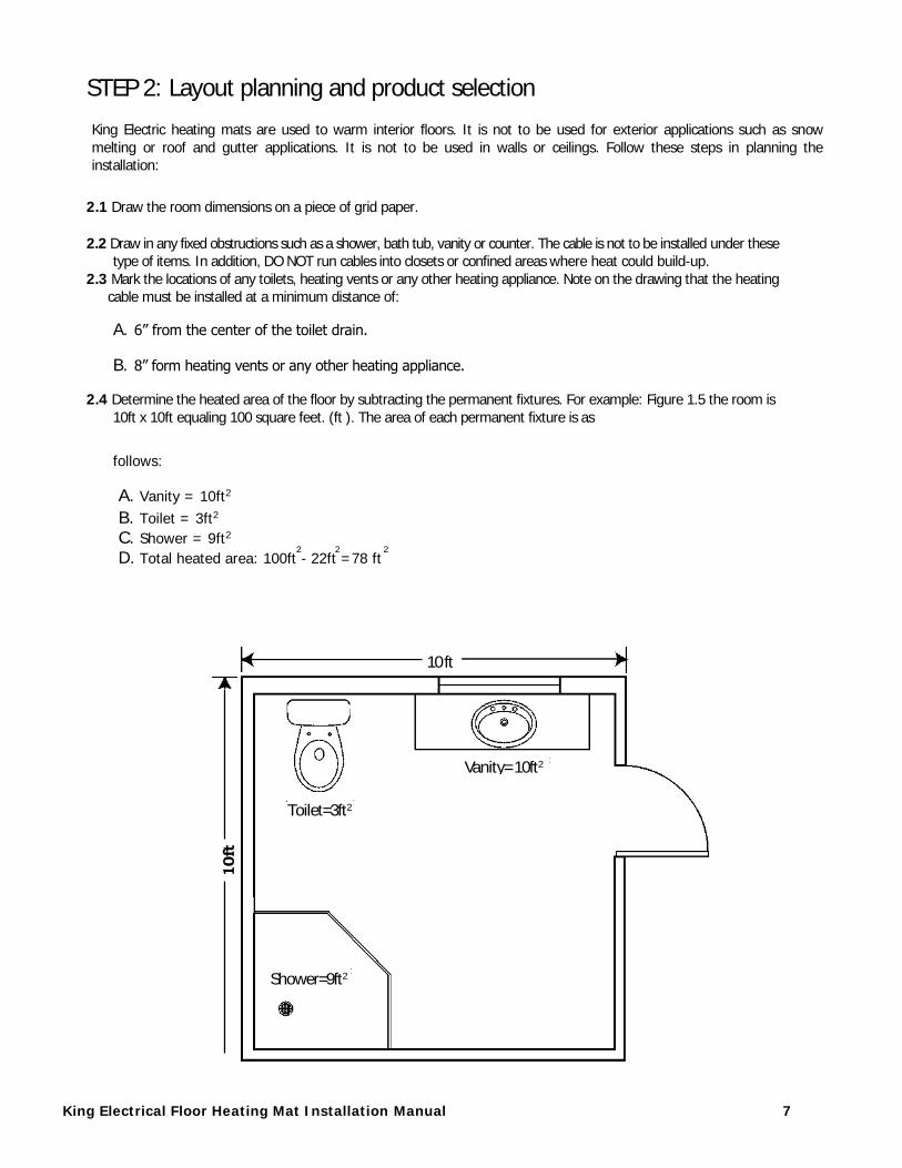
2.4 Determine the heated area of the floor by subtracting the permanent fixtures. For example: Figure 1.5 the room is
10ft x 10ft equaling 100 square feet. (ft ). The area of each permanent fixture is as
follows:
A. Vanity = 10ft2
B. Toilet = 3ft2
C. Shower = 9ft2
D. Total heated area: 100ft - 22ft =78 ft
10ft
Shower=9ft2
Toilet=3ft2
10 ft
Vanity= 10ft2
2 2 2
King Electrical Floor Heating Mat Installation Manual 8
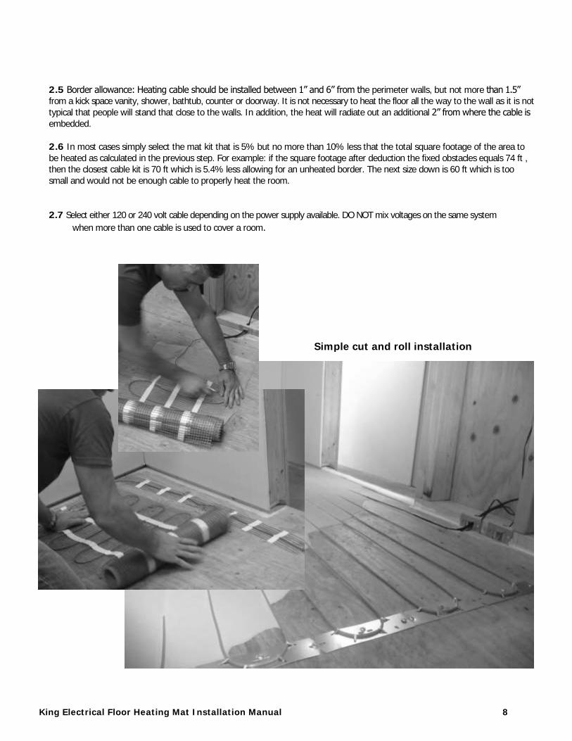
2.5 Border allowance: Heating cable should be installed between 1” and 6” from the perimeter walls, but not more than 1.5” from a kick space vanity, shower, bathtub, counter or doorway. It is not necessary to heat the floor all the way to the wall as it is not
typical that people will stand that close to the walls. In addition, the heat will radiate out an additional 2” from where the cable is
embedded.
2.6 In most cases simply select the mat kit that is 5% but no more than 10% less that the total square footage of the area to
be heated as calculated in the previous step. For example: if the square footage after deduction the fixed obstacles equals 74 ft , then the closest cable kit is 70 ft which is 5.4% less allowing for an unheated border. The next size down is 60 ft which is too
small and would not be enough cable to properly heat the room.
2.7 Select either 120 or 240 volt cable depending on the power supply available. DO NOT mix voltages on the same system
when more than one cable is used to cover a room.
Simple cut and roll installation
STEP 3: Thermostat location and strapping layout (continued)
King Electrical Floor Heating Mat Installation Manual 9
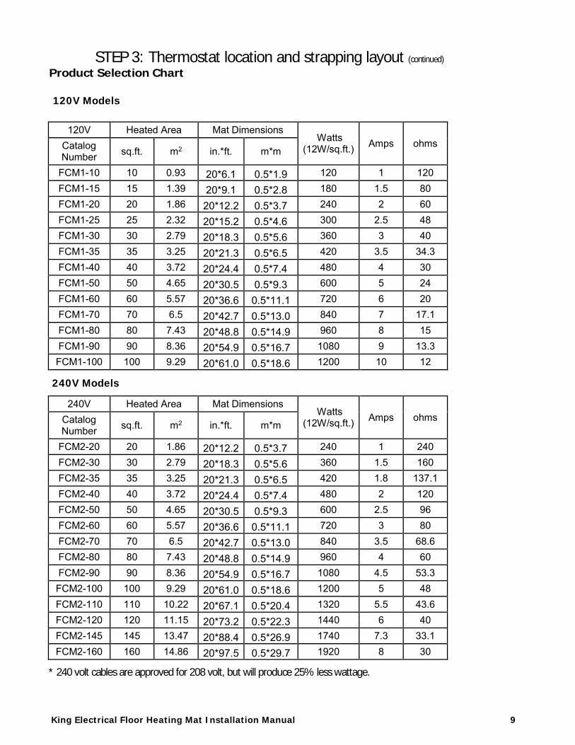
Product Selection Chart
120V Heated Area Mat Dimensions Watts
(12W/sq.ft.) Amps ohms Catalog Number sq.ft. m2 in.*ft. m*m
FCM1-10 10 0.93 20*6.1 0.5*1.9 120 1 120 FCM1-15 15 1.39 20*9.1 0.5*2.8 180 1.5 80 FCM1-20 20 1.86 20*12.2 0.5*3.7 240 2 60 FCM1-25 25 2.32 20*15.2 0.5*4.6 300 2.5 48 FCM1-30 30 2.79 20*18.3 0.5*5.6 360 3 40 FCM1-35 35 3.25 20*21.3 0.5*6.5 420 3.5 34.3 FCM1-40 40 3.72 20*24.4 0.5*7.4 480 4 30 FCM1-50 50 4.65 20*30.5 0.5*9.3 600 5 24 FCM1-60 60 5.57 20*36.6 0.5*11.1 720 6 20 FCM1-70 70 6.5 20*42.7 0.5*13.0 840 7 17.1 FCM1-80 80 7.43 20*48.8 0.5*14.9 960 8 15 FCM1-90 90 8.36 20*54.9 0.5*16.7 1080 9 13.3 FCM1-100 100 9.29 20*61.0 0.5*18.6 1200 10 12
240V Heated Area Mat Dimensions Watts
(12W/sq.ft.) Amps ohms Catalog Number sq.ft. m2 in.*ft. m*m
FCM2-20 20 1.86 20*12.2 0.5*3.7 240 1 240 FCM2-30 30 2.79 20*18.3 0.5*5.6 360 1.5 160 FCM2-35 35 3.25 20*21.3 0.5*6.5 420 1.8 137.1 FCM2-40 40 3.72 20*24.4 0.5*7.4 480 2 120 FCM2-50 50 4.65 20*30.5 0.5*9.3 600 2.5 96 FCM2-60 60 5.57 20*36.6 0.5*11.1 720 3 80 FCM2-70 70 6.5 20*42.7 0.5*13.0 840 3.5 68.6 FCM2-80 80 7.43 20*48.8 0.5*14.9 960 4 60 FCM2-90 90 8.36 20*54.9 0.5*16.7 1080 4.5 53.3 FCM2-100 100 9.29 20*61.0 0.5*18.6 1200 5 48 FCM2-110 110 10.22 20*67.1 0.5*20.4 1320 5.5 43.6 FCM2-120 120 11.15 20*73.2 0.5*22.3 1440 6 40 FCM2-145 145 13.47 20*88.4 0.5*26.9 1740 7.3 33.1 FCM2-160 160 14.86 20*97.5 0.5*29.7 1920 8 30
120V Models
240V Models
* 240 volt cables are approved for 208 volt, but will produce 25% less wattage.

King Electrical Floor Heating Mat Installation Manual 10
f
t
.
8
0
Leng
t
h
m
2
4
.
4
2
15
Heated area spacing (ft2)
3 4 Watts Amps 20 25 240 1.0
Fast
Set Ohms
Strapping
240.0 20 f t .
3.2 Determine the direction of the cable runs. It is recommended that the cable run parallel to the wall that the
thermostat is mounted. 48 inches. Center straps should be 3 to 4 feet apart.
3.3 On average, a 5 to 10% deduction in heated area will create a 2-4” border. To determine the exact distance to mount the mat from the wall, take the actual room square footage less the selected mat kit less to
determine the unheated border. Then take the unheated border and divide it by the perimeter. Now multiply by 12 for the number
of inches to mount the mat away from the wall.
A. 10ft x 10ft room = 100 ft 2
B. 4ft x 10ft = 40 ft perimeter
C. Mat kit selected 90 ft
D. 100ft - 90 ft = 10ft unheated border
E. 10ft / 40ft = .25ft
F. .25ft x 12in/ft = 3” from the wall
3.4 It is difficult to predict exactly where the heating cable will end, thus it is important to have a buffer zone. A buffer zone is an area where heating in not essential and if unheated will go unnoticed. This area is also used for any excess
cable where a higher heated density will also be un-noticed.
STEP 3: Thermostat location
3.1 Mark the location of the thermostat on the drawing. This is where the cold lead will drop from the wall box and
become the starting point for the heating cable as well as where the floor sensor will be installed.
End Splice
2
2
Cold Lead
T Thermostat
STEP 3: Thermostat location and strapping layout (continued)
King Electrical Floor Heating Mat Installation Manual 11
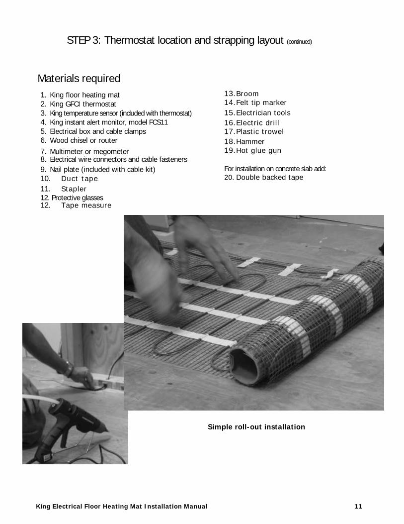
Materials required
1. King floor heating mat
2. King GFCI thermostat
3. King temperature sensor (included with thermostat)
4. King instant alert monitor, model FCS11
5. Electrical box and cable clamps
6. Wood chisel or router
7. Multimeter or megometer 8. Electrical wire connectors and cable fasteners
9. Nail plate (included with cable kit)
10. Duct tape
11. Stapler 12. Protective glasses 12. Tape measure
13. Broom
14. Felt tip marker
15. Electrician tools
16. Electric drill 17. Plastic trowel
18. Hammer
19. Hot glue gun
For installation on concrete slab add: 20. Double backed tape
Simple roll-out installation
King Electrical Floor Heating Mat Installation Manual 12
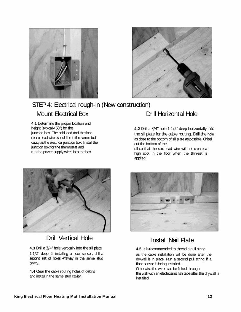
STEP 4: Electrical rough-in (New construction)
Mount Electrical Box Drill Horizontal Hole
4.1 Determine the proper location and height (typically 60”) for the
junction box. The cold lead and the floor sensor lead wires should be in the same stud
cavity as the electrical junction box. Install the
junction box for the thermostat and run the power supply wires into the box.
Drill Vertical Hole
4.3 Drill a 3/4” hole vertically into the sill plate
1-1/2” deep. If installing a floor sensor, drill a second set of holes 4”away in the same stud
cavity.
4.4 Clear the cable routing holes of debris
and install in the same stud cavity.
4.2 Drill a 3/4” hole 1-1/2” deep horizontally into the sill plate for the cable routing. Drill the hole
as close to the bottom of sill plate as possible. Chisel out the bottom of the
sill so that the cold lead wire will not create a high spot in the floor when the thin-set is
applied.
Install Nail Plate 4.5 It is recommended to thread a pull string
as the cable installation will be done after the
drywall is in place. Run a second pull string if a floor sensor is being installed.
Otherwise the wires can be fished through
the wall with an electrician’s fish tape after the drywall is installed.
King Electrical Floor Heating Mat Installation Manual 13
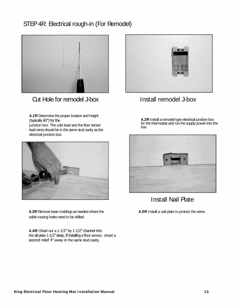
STEP 4R: Electrical rough-in (For Remodel)
Cut Hole for remodel J-box Install remodel J-box
4.1R Determine the proper location and height
(typically 60”) for the
junction box. The cold lead and the floor sensor lead wires should be in the same stud cavity as the
electrical junction box.
4.2R Install a remodel type electrical junction box for the thermostat and run the supply power into the box.
Install Nail Plate
4.3R Remove base moldings as needed where the 4.5R Install a nail plate to protect the wires.
cable routing holes need to be drilled.
4.4R Chisel out a 1-1/2” by 1-1/2” channel into the sill plate 1-1/2” deep. If installing a floor sensor, chisel a
second relief 4” away in the same stud cavity.
King Electrical Floor Heating Mat Installation Manual 14
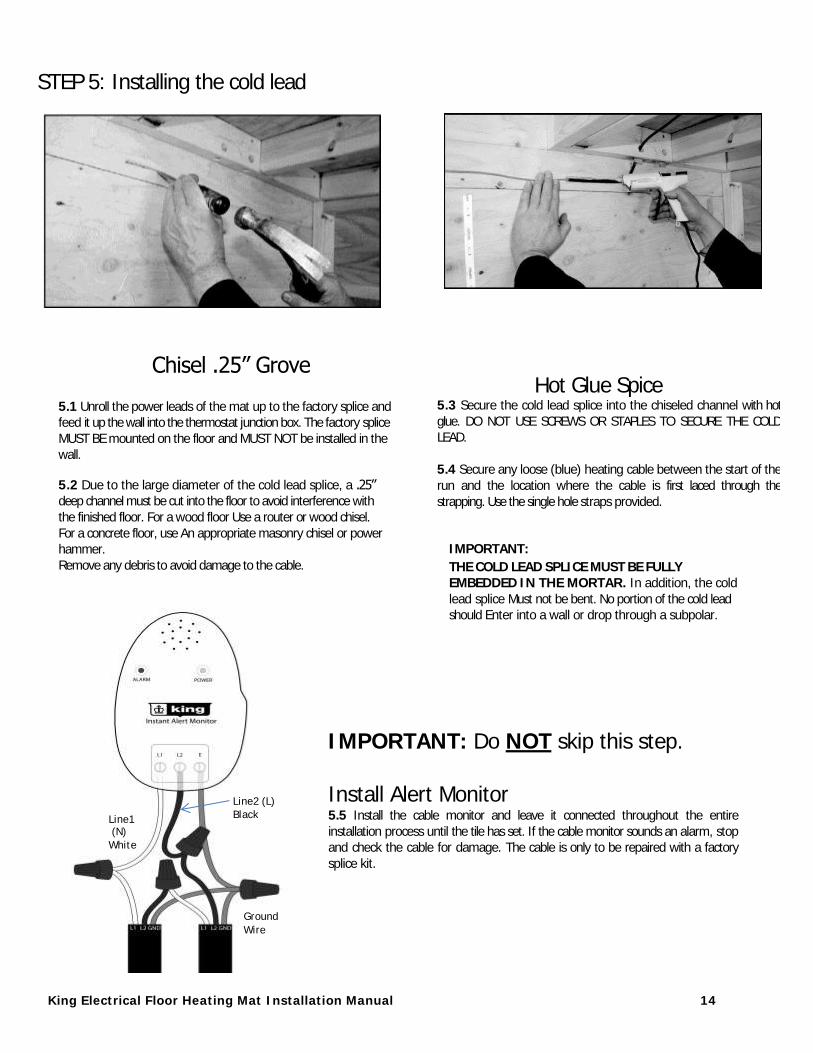
STEP 5: Installing the cold lead
Chisel .25” Grove
5.1 Unroll the power leads of the mat up to the factory splice and feed it up the wall into the thermostat junction box. The factory splice
MUST BE mounted on the floor and MUST NOT be installed in the wall.
5.2 Due to the large diameter of the cold lead splice, a .25” deep channel must be cut into the floor to avoid interference with
the finished floor. For a wood floor Use a router or wood chisel.
For a concrete floor, use An appropriate masonry chisel or power hammer.
Remove any debris to avoid damage to the cable.
Hot Glue Spice 5.3 Secure the cold lead splice into the chiseled channel with hot
glue. DO NOT USE SCREWS OR STAPLES TO SECURE THE COLD LEAD.
5.4 Secure any loose (blue) heating cable between the start of the
run and the location where the cable is first laced through the
strapping. Use the single hole straps provided.
IMPORTANT:
THE COLD LEAD SPLICE MUST BE FULLY EMBEDDED IN THE MORTAR. In addition, the cold
lead splice Must not be bent. No portion of the cold lead should Enter into a wall or drop through a subpolar.
IMPORTANT: Do NOT skip this step. Install Alert Monitor 5.5 Install the cable monitor and leave it connected throughout the entire
installation process until the tile has set. If the cable monitor sounds an alarm, stop and check the cable for damage. The cable is only to be repaired with a factory
splice kit.
Line2 (L)
Black Line1 (N)
White
Ground
Wire
King Electrical Floor Heating Mat Installation Manual 15
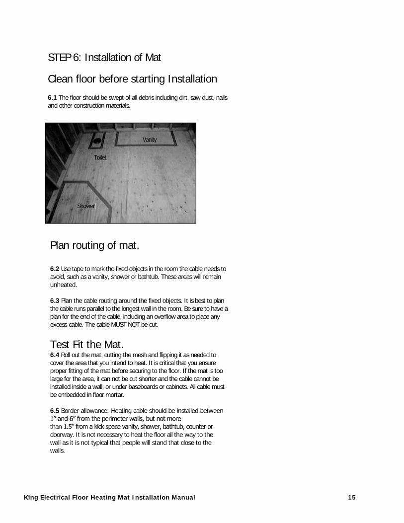
STEP 6: Installation of Mat
Clean floor before starting Installation
6.1 The floor should be swept of all debris including dirt, saw dust, nails and other construction materials.
Plan routing of mat. 6.2 Use tape to mark the fixed objects in the room the cable needs to avoid, such as a vanity, shower or bathtub. These areas will remain
unheated.
6.3 Plan the cable routing around the fixed objects. It is best to plan
the cable runs parallel to the longest wall in the room. Be sure to have a plan for the end of the cable, including an overflow area to place any
excess cable. The cable MUST NOT be cut.
Test Fit the Mat. 6.4 Roll out the mat, cutting the mesh and flipping it as needed to
cover the area that you intend to heat. It is critical that you ensure proper fitting of the mat before securing to the floor. If the mat is too
large for the area, it can not be cut shorter and the cable cannot be installed inside a wall, or under baseboards or cabinets. All cable must
be embedded in floor mortar.
6.5 Border allowance: Heating cable should be installed between
1” and 6” from the perimeter walls, but not more than 1.5” from a kick space vanity, shower, bathtub, counter or
doorway. It is not necessary to heat the floor all the way to the
wall as it is not typical that people will stand that close to the walls.
King Electrical Floor Heating Cable Installation Manual 16
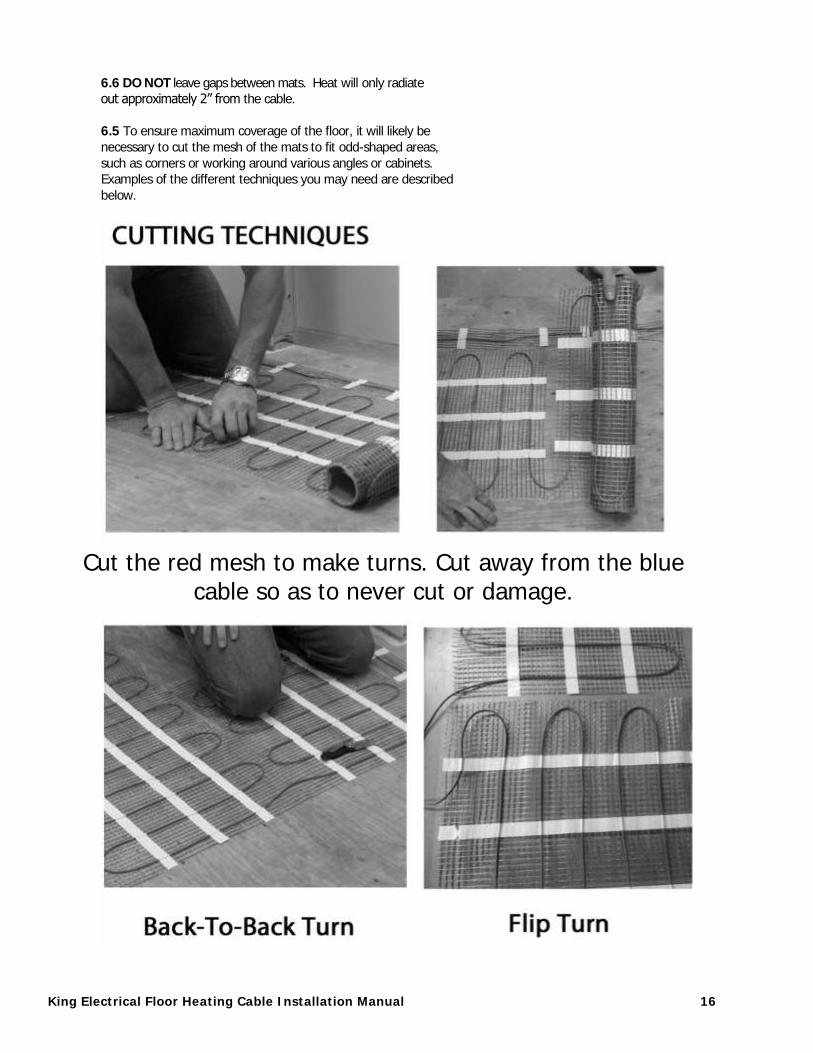
6.6 DO NOT leave gaps between mats. Heat will only radiate out approximately 2” from the cable.
6.5 To ensure maximum coverage of the floor, it will likely be
necessary to cut the mesh of the mats to fit odd-shaped areas,
such as corners or working around various angles or cabinets. Examples of the different techniques you may need are described
below.
Cut the red mesh to make turns. Cut away from the blue cable so as to never cut or damage.
King Electrical Floor Heating Mat Installation Manual 17
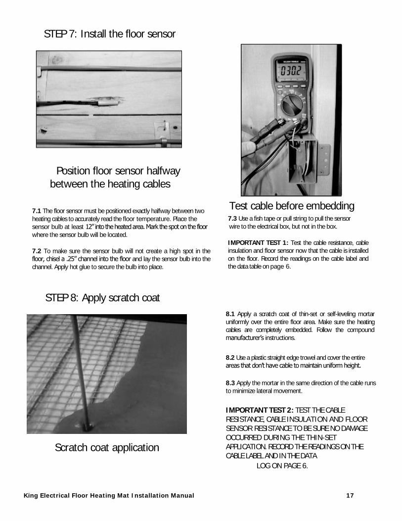
Test cable before embedding 7.3 Use a fish tape or pull string to pull the sensor
wire to the electrical box, but not in the box.
IMPORTANT TEST 1: Test the cable resistance, cable insulation and floor sensor now that the cable is installed
on the floor. Record the readings on the cable label and the data table on page 6.
STEP 7: Install the floor sensor
Position floor sensor halfway
between the heating cables
7.1 The floor sensor must be positioned exactly halfway between two
heating cables to accurately read the floor temperature. Place the sensor bulb at least 12” into the heated area. Mark the spot on the floor
where the sensor bulb will be located.
7.2 To make sure the sensor bulb will not create a high spot in the floor, chisel a .25” channel into the floor and lay the sensor bulb into the
channel. Apply hot glue to secure the bulb into place.
STEP 8: Apply scratch coat 8.1 Apply a scratch coat of thin-set or self-leveling mortar
uniformly over the entire floor area. Make sure the heating cables are completely embedded. Follow the compound
manufacturer’s instructions.
8.2 Use a plastic straight edge trowel and cover the entire areas that don’t have cable to maintain uniform height.
8.3 Apply the mortar in the same direction of the cable runs to minimize lateral movement.
IMPORTANT TEST 2: TEST THE CABLE RESISTANCE, CABLE INSULATION AND FLOOR SENSOR RESISTANCE TO BE SURE NO DAMAGE OCCURRED DURING THE THIN-SET APPLICATION. RECORD THE READINGS ON THE CABLE LABEL AND IN THE DATA
LOG ON PAGE 6.
Scratch coat application

King Electrical Floor Heating Mat Installation Manual 18
STEP 9: Install the wall thermostat
Follow the thermostat manufacturer’s instructions.
9.1 Before starting any wiring, verify that the power supply is turned off.
9.2 Connect the power supply wires and the load side heating wires.
Follow the thermostat manufacturer’s instructions.
9.3 Connect the floor sensor wires to the thermostat. These are low voltage wires
and should not enter the line voltage junction box. These low voltage wires typically run through the wall and connect into the face of the thermostat away from the line
voltage wires.
CAUTION: Allow mortar compound to completely cure before energizing cable. This will ensure that the setting of the mortar mix will not be compromised by the heat of the cables. Refer to compound manufacturer’s instructions for curing times.
Line1 (L) Black
Line2 (N) White
Load1 Black
Load2 White
Ground Wire
Small Screwdriver
Floor Sensor
Example of Floor Sensor Wiring
Example of Thermostat wiring diagram
King Electrical Mfg. Company will repair or replace, without charge to the original owner, any heating cable found to be defective or malfunctioning within the 20 year warranty. In Case of Product Failure: Contact King Electrical Mfg. Co. at 800.603.5464. The owner will be required to provide, within the designated warranty period, the following information: model number, date of purchase, and a complete description of the problem encountered with product. Upon receipt of the aforementioned, the company will reply to the owner within a period not to exceed fifteen (15) working days, and will provide the action to be taken by owner. Terms: This warranty requires the owner or his agent install the equipment in accordance with the National Electrical Code, any other applicable heating or electrical codes and the manufacturer's installation instructions. It further requires that reasonable
and necessary maintenance be performed on the unit. Failure of proper maintenance by owner will void the warranty in its entirety. The company is not liable for any actions it deems to be abuse or misuse of the product. The customer shall be responsible for all costs incurred in the removal or reinstallation of products, including, but not limited to, labor costs, and shipping costs incurred to return products to King Manufacturing. At their discretion, King Manufacturing will decide to either repair or replace the product, with no charge to the owner, with return freight paid by King. The Company shall not be liable for consequential damages arising with respect to the product, whether based upon negligence, tort, strict liability or contract. No other written or oral warranty applies, nor any warranties by Representatives, Dealers, Employees of King or any other person. King Manufacturing can be contacted by phone at 206.762.0400, fax 206.763.7738 or website www.king-electric.com. The company's minimum liability shall not in any case exceed the list price for the product claimed to be defective.
King Electrical Floor Heating Cable Installation Manual 19
mat series
9131 10th Avenue South
Seattle, WA 98108
Tel: 800.603.5464 – Fax: 206-763-7738
www.king-electric.com