Embed Size (px)
Citation preview
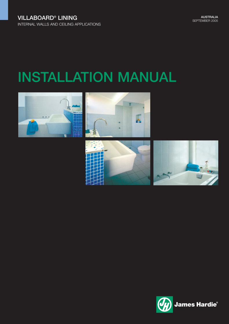
AUSTRALIASEPTEMBER 2005
INSTALLATION MANUAL
VILLABOARD® LININGINTERNAL WALLS AND CEILING APPLICATIONS

1 INTRODUCTION
James Hardie Villaboard® lining is a premium sanded fibre cement sheetwith recessed edges for flush jointing. Villaboard lining is an ideal lining forbathrooms, laundries, kitchens and high traffic abuse areas.
The main features of Villaboard lining are:
� Durable wet area lining sheet.
� Creates suitable surface for tiles, paint or wallpaper.
� Long edges recessed for easy flush-jointing.
� Reliable impact resistant lining. Ideal for wall lining in commercialapplications where walls are prone to damage.
� Suitable for use in fire and acoustically rated systems.
This manual covers the use of Villaboard lining in internal wall and ceilingapplications. Further technical literature relating to Villaboard lining isavailable from James Hardie in the following manuals:
� Eaves and soffits Technical Specification.
� Wet area construction Design Manual.
� Fire and acoustically rated walls technical manuals.
The specifier or other responsible party for the project must ensure theinformation and details in this guide are appropriate for the intendedapplication and that specific design and detailing is undertaken for areaswhich fall outside the scope of this documentation.
Make sure your information is up to dateWhen specifying or installing James Hardie products, ensure you have thecurrent manual. If you’re not sure you do, or you need more information,visit www.jameshardie.com.au or Ask James Hardie™ on 13 11 03.
CONTENTS1 INTRODUCTION 2
2 SAFE WORKING PRACTICES 4Warning 4Recommended safe working practices 4Working instructions 4Hole-forming 5Storage and handling 5Quality 5
3 FRAMING / SUBSTRATE 6General 6Timber 6Steel 6Masonry/concrete/AAC 6Frame tolerances 6Masonry/concrete/AAC tolerances 6Curved walls 6
4 SHEET LAYOUT 7General 7
5 INSTALLATION 7General 7Fasteners 8Fixing to framed walls 8Fixing to framed ceilings 9Fixing to masonry/concrete AAC 10Batten/furring channels 10Autoclaved aerated concrete (AAC) 11
6 JOINTS 12General 12Set joints 12Butt joints 14Internal corners 15External corners 15Control joints 15
7 FINISHES AND MAINTENANCE 16General 16Glancing light 16Level of finishes 16Paint finishes 17Cornices 17Tiled finishes 17Maintenance 17
8 PRODUCT INFORMATION 17General 17Product mass 17Durability 17
9 WARRANTY 19
WE VALUE YOUR FEEDBACKTo continuously improve the development of our products andsystems, we value your input. Please send any suggestions,including your name, contact details, and relevant sketches to:
Ask James Hardie™
Fax 02 9638 [email protected]
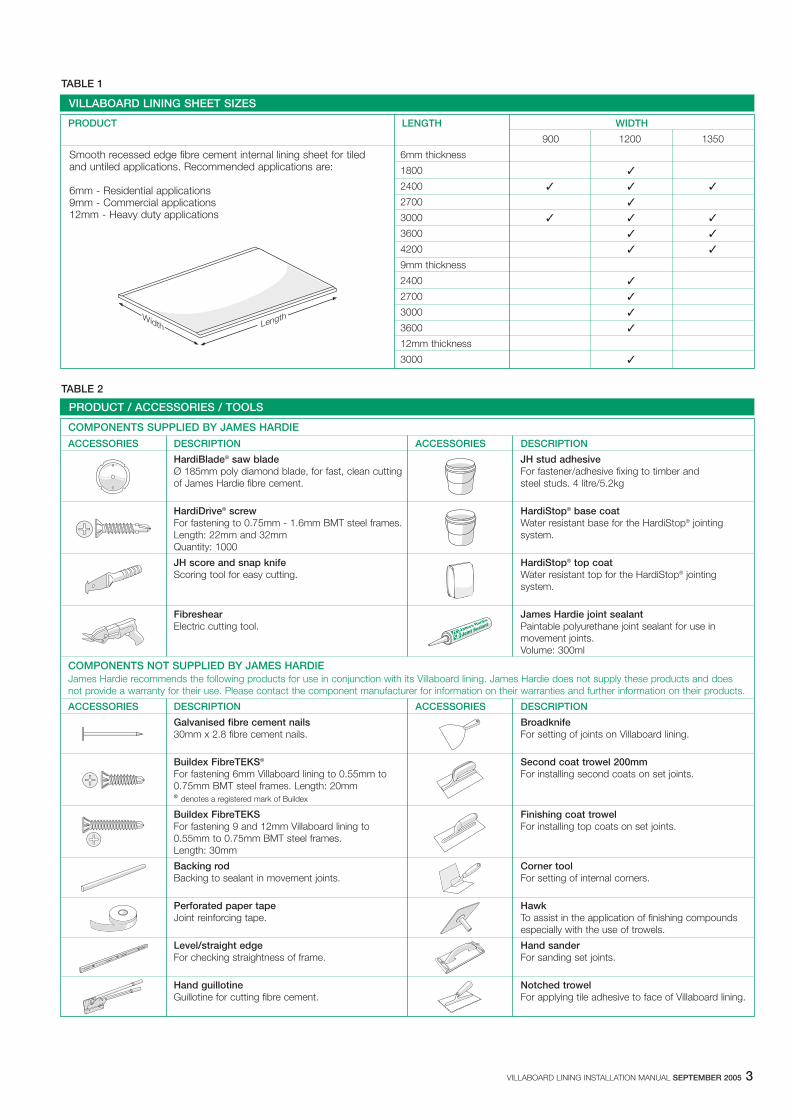
TABLE 1
TABLE 2
VILLABOARD LINING SHEET SIZES
PRODUCT LENGTH WIDTH
900 1200 1350
6mm thickness
1800 �
2400 � � �
2700 �
3000 � � �
3600 � �
4200 � �
9mm thickness
2400 �
2700 �
3000 �
3600 �
12mm thickness
3000 �
Smooth recessed edge fibre cement internal lining sheet for tiledand untiled applications. Recommended applications are:
6mm - Residential applications9mm - Commercial applications12mm - Heavy duty applications
LengthWidth
PRODUCT / ACCESSORIES / TOOLS
COMPONENTS SUPPLIED BY JAMES HARDIE
ACCESSORIES DESCRIPTION ACCESSORIES DESCRIPTION
HardiBlade® saw blade JH stud adhesiveØ 185mm poly diamond blade, for fast, clean cutting For fastener/adhesive fixing to timber and of James Hardie fibre cement. steel studs. 4 litre/5.2kg
HardiDrive® screw HardiStop® base coatFor fastening to 0.75mm - 1.6mm BMT steel frames. Water resistant base for the HardiStop® jointingLength: 22mm and 32mm system.Quantity: 1000
JH score and snap knife HardiStop® top coatScoring tool for easy cutting. Water resistant top for the HardiStop® jointing
system.
Fibreshear James Hardie joint sealantElectric cutting tool. Paintable polyurethane joint sealant for use in
movement joints.Volume: 300ml
COMPONENTS NOT SUPPLIED BY JAMES HARDIEJames Hardie recommends the following products for use in conjunction with its Villaboard lining. James Hardie does not supply these products and does not provide a warranty for their use. Please contact the component manufacturer for information on their warranties and further information on their products.
ACCESSORIES DESCRIPTION ACCESSORIES DESCRIPTION
Galvanised fibre cement nails Broadknife30mm x 2.8 fibre cement nails. For setting of joints on Villaboard lining.
Buildex FibreTEKS® Second coat trowel 200mmFor fastening 6mm Villaboard lining to 0.55mm to For installing second coats on set joints.0.75mm BMT steel frames. Length: 20mm® denotes a registered mark of Buildex
Buildex FibreTEKS Finishing coat trowelFor fastening 9 and 12mm Villaboard lining to For installing top coats on set joints.0.55mm to 0.75mm BMT steel frames.Length: 30mm
Backing rod Corner toolBacking to sealant in movement joints. For setting of internal corners.
Perforated paper tape HawkJoint reinforcing tape. To assist in the application of finishing compounds
especially with the use of trowels.
Level/straight edge Hand sanderFor checking straightness of frame. For sanding set joints.
Hand guillotine Notched trowelGuillotine for cutting fibre cement. For applying tile adhesive to face of Villaboard lining.
VILLABOARD LINING INSTALLATION MANUAL SEPTEMBER 2005 3

4 VILLABOARD LINING INSTALLATION MANUAL SEPTEMBER 2005
2 SAFE WORKING PRACTICES
WORKING INSTRUCTIONSRefer to recommended safe working practices before starting any cuttingor machining of product.
Score and SnapScore and snap is a fast and efficient method of cutting James Hardiebuilding products using James Hardie’s special tungsten tipped scoreand snap knife.
Preferably score on the face side of the product. Score against a straightedge and repeat the action to obtain adequate depth for clean break –normally one third of sheet thickness. Snap upwards to achieve break.Smooth any rough edges with a rasp.
Hand guillotineMake guillotine cut on the off-cut side of line to allow for the thickness ofthe blade.
FibreshearAn electrically powered, fast, clean and effortless way of cutting JamesHardie building products, especially around curves such as archways.Make fibreshear cut on the ‘off-cut’ side of the line to allow for thethickness of the shear.
WARNING - DO NOT BREATHE DUST AND CUTONLY IN WELL VENTILATED AREAJames Hardie products contain sand, a source of respirable crystallinesilica which is considered by some international authorities to be a causeof cancer from some occupational sources. Breathing excessive amountsof respirable silica dust can also cause a disabling and potentially fatallung disease called silicosis, and has been linked with other diseases.Some studies suggest smoking may increase these risks. Duringinstallation or handling: (1) work in outdoor areas with ample ventilation; (2) minimise dust when cutting by using either ‘score and snap’ knife, fibrecement shears or, where not feasible, use a HardiBlade® saw blade anddust-reducing circular saw attached to a HEPA vacuum; (3) warn others inthe immediate area to avoid breathing dust; (4) wear a properly-fitted,approved dust mask or respirator (e.g. P1 or P2) in accordance withapplicable government regulations and manufacturer instructions to furtherlimit respirable silica exposures. During clean-up, use HEPA vacuums orwet cleanup methods - never dry sweep. For further information, refer toour installation instructions and Material Safety Data Sheets available atwww.jameshardie.com.au. FAILURE TO ADHERE TO OUR WARNINGS,MATERIAL SAFETY DATA SHEETS, AND INSTALLATION INSTRUCTIONSMAY LEAD TO SERIOUS PERSONAL INJURY OR DEATH.
JAMES HARDIE RECOMMENDED SAFE WORKING PRACTICES
CUTTING OUTDOORS1. Position cutting station so wind will blow dust away from the user or
others in working area.2. Use one of the following methods based on the required cutting rate:
Best� Score and snap� Hand guillotine� FibreshearGood� Dust reducing circular saw equipped with HardiBlade® saw blade
and HEPA vacuum extraction.
CUTTING INDOORS� Cut only using score and snap, hand guillotine or fibreshears
(manual, electric or pneumatic).� Position cutting station in a well-ventilated area.
REBATING/SANDING/DRILLING/OTHER MACHININGWhen rebating, sanding, drilling or machining you should always wear a P1or P2 dust mask and warn others in the immediate area.
IMPORTANT NOTES1. For maximum protection (lowest respirable dust production), James
Hardie recommends always using “Best” - level cutting methods where feasible.
2. NEVER use a power saw indoors.3. NEVER use a circular saw blade that does not carry the HardiBlade® logo.4. NEVER dry sweep - Use wet suppression or HEPA vacuum.5. NEVER use grinders.6. ALWAYS follow tool manufacturers’ safety recommendations.
P1 or P2 respirators should be used in conjunction with above cuttingpractices to further reduce dust exposures. Additional exposure informationis available at www.jameshardie.com.au to help you determine the mostappropriate cutting method for your job requirements. If concern still existsabout exposure levels or you do not comply with the above practices, youshould always consult a qualified industrial hygienist or contact James Hardie for further information.
Scored edge Straight edge

VILLABOARD LINING INSTALLATION MANUAL SEPTEMBER 2005 5
HardiBlade® saw bladeThe HardiBlade® saw blade used with a dust-reducing saw and HEPAvacuum extraction allows for fast, clean cutting of James Hardie fibrecement products. A dust-reducing saw uses a dust deflector or a dustcollector which can be connected to a vacuum system. When sawing,clamp a straight-edge to the sheet as a guide and run the saw base platealong the straight edge when making the cut.
HOLE-FORMINGFor smooth clean cut circular holes:� Mark the centre of the hole on the sheet.� Pre-drill a pilot hole.� Using the pilot hole as a guide, cut the hole to the appropriate diameter
with a hole saw fitted to a heavy duty electric drill.
For irregular holes:� Small rectangular or circular holes can be cut by drilling a series of small
holes around the perimeter of the hole then tapping out the waste piecefrom the sheet face.
� Tap carefully to avoid damage to sheets, ensuring the sheet edges areproperly supported.
STORAGE AND HANDLINGTo avoid damage, all James Hardie building products should be storedwith edges and corners of the sheets protected from chipping.
James Hardie building products must be installed in a dry state andprotected from rain during transport and storage. The product must belaid flat under cover on a smooth level surface clear of the ground toavoid exposure to water, moisture, etc.
QUALITYJames Hardie conducts stringent quality checks to ensure any productmanufactured falls within our quality spectrum. It is the responsibility ofthe builder to ensure the product meets aesthetic requirements beforeinstallation. James Hardie will not be responsible for rectifying obviousaesthetic surface variations following installation.

FRAME TOLERANCESEnsure frame is square and work from a central datum line. Frames mustbe straight and true to provide a flush face to receive the sheeting.
A suggested maximum tolerance of between 3mm and 4mm in any3000mm length of frame will give best results. Villaboard lining will notstraighten excessively warped or distorted frames and any warping maystill be visible after the internal lining is applied.
MASONRY/CONCRETE/AAC TOLERANCESCut Villaboard lining approximately 15mm less than floor to ceiling heightto allow for building tolerances. Ensure a 5-10mm building tolerance gapis provided at the floor and ceiling junctions with the Villaboard lining. SeePage 10 for specific substrate requirements.
CURVED WALLSVillaboard lining may be bent to accommodate curved walls. The minimum bending radii are shown below.
TABLE 3
NOTES1. The bending radii given above require no special pre-wetting of the
sheet and may be used on internal or external curves.2. With extra care, the sheets can be bent to the values shown in the
brackets.
To maintain the smoothness of the curve, studs are generally required atspacings as shown below.
TABLE 4
*or at one third of the sheet width, whichever is the lesser.
6 VILLABOARD LINING INSTALLATION MANUAL SEPTEMBER 2005
3 FRAMING / SUBSTRATE
GENERALVillaboard lining can be fixed to either timber framing, light gaugedomestic type steel framing and masonry, concrete or autoclavedaerated concrete (AAC) substrates. The framing and substrate used mustcomply with the relevant building regulations and standards and therequirements of this manual.
NOTE Stud spacings restrict the thickness of tiles used to finish Villaboard lining.For more information refer to the Finishes and Maintenance section onpage 16.
TIMBERUse only seasoned timber. Unseasoned timber must not be used as it isprone to shrinkage and can cause Villaboard lining and frames to move.Studs must not be less than 38mm wide at joints.
‘Timber used for house construction must have the level of durabilityappropriate for the relevant climate and expected service life andconditions including exposure to insect attacks or to moisture, whichcould cause decay.’
Reference AS1684.2 - 1999 ‘Residential Timber Framed Construction’.
STEELThe minimum size for steel stud framing should be 64mm deep x0.55mm base metal thickness (BMT).
Steel framing must be designed in accordance with AS/NZS 4600 ‘ColdFormed Steel Structures’.
Steel sections shall be galvanised or zinc coated of 0.55mm - 1.6mmBase Metal Thickness (BMT). Studs must not be less than 38mm wide at joints.
MASONRY/CONCRETE/AACAlways ensure the substrate is given adequate time to dry out beforeinstallation of Villaboard lining. The wall surface must be clean, dry andfree of any material that will reduce an effective bond (e.g. dust, loosepaint, oil, drummy render, waterproofing or other agents, etc).
Chase walls, install services and secure to wall prior to fixing Villaboard lining.
FIGURE 1 FRAME STRAIGHTNESS
CURVED WALL MINIMUM BENDING RADII
Along length (mm) Across width (mm)
6mm Villaboard lining 1800 (1200) 2400
9mm Villaboard lining 3000 (1800) 4000
CURVED LINING - STUD SPACING
RANGE OF RADII (mm) STUD SPACING (mm)
1200 150
Above 1200 to 1800 200
Above 1800 to 3000 300
Above 3000 to 20000 *450
Above 20000 *600

VILLABOARD LINING INSTALLATION MANUAL SEPTEMBER 2005 7
4 SHEET LAYOUT
GENERALInstall Villaboard lining across the framing, i.e. place the long edges of thesheet at right angles to the framing members. Villaboard lining can befixed either horizontally or vertically, however horizontal fixing isrecommended as the most convenient method in residential applications.
Sheet joints must coincide with the centre line of the framing member. Atdoor and window openings, fix sheets around the opening so sheetedges do not coincide with the side of the door or window by a minimumdistance 200mm. See Figure 2.
FIGURE 2 SHEET LAYOUT
5 INSTALLATION
GENERALPlace 6mm packers along floor as temporary support for sheets. This willallow for any frame movement/shrinkage. Put first sheet in place as shown.
Ensuring the sheet is level, fix the first sheet starting from the centre ofsheet and working outwards to avoid any drumminess.
Fix remaining sheets in similar sequence.
NOTES1. For fastener selection and spacings see pages 8-11.2. Do not fix sheets to the bottom chord of roof trusses. Instead, fix to
battens or furring channels.
FIGURE 3 FIRST SHEET
FIGURE 4 FIXING FIRST SHEET
FIGURE 5 FIXING REMAINING SHEETS
200mmmin.
600mm max. stud centres
Villaboard lininglaid across framingmembers
Villaboard lininglaid in brick pattern
Sheet endsmust be staggeredon framing members
Butt joints supported onframe. Ensure they do notcoincide with openings
250mmmin.
200mmmin.

8 VILLABOARD LINING INSTALLATION MANUAL SEPTEMBER 2005
FASTENERSFasteners must have the appropriate level of durability required for theintended project.
Fasteners must be fully compatible with all other material that they are incontact with to ensure the durability and integrity of the assembly.
Contact fastener manufacturers for more information.
For timber, use 30mm x 2.8mm galvanised fibre cement nails with aminimum head diameter of 6mm.
For fixing 6mm Villaboard lining to 0.55 – 0.75mm BMT steel framing,use 20mm Buildex FibreTEKS screws (use 30mm screws for 9 and12mm sheets). For fixing 6mm Villaboard lining to 0.75 – 1.6mm BMTsteel framing, use 22mm HardiDrive® screws (use 32mm screws for 9mmand 12mm sheets).
Fasteners should be driven flush as shown in Figure 6. Fasteners shouldbe screwed as close as possible to the stud corners to avoid deflectionof the stud flange, see Figure 7.
FIXING TO FRAMED WALLSUntiled wallsWhere Villaboard lining is to be left untiled, the sheets can be fixed withfasteners or a combination of fasteners and adhesive, see Figures 8 and 9 respectively.
FIGURE 6 FASTENER DEPTH
FIGURE 7 SCREW FASTENING
NOTES1. When installing skirting tiles up to 300mm in height only fasten the
bottom of the sheet to the bottom plate at 200mm maximum centres.2. All surfaces to receive adhesive must be clean, free of dust, oil, etc.3. Ensure daubs of adhesive never coincide with permanent fastener
points, as adhesive shrinkage may cause fastener head protrusion.4. When fixing cornices it is recommended that Villaboard lining is
wetted with a sponge prior to adhesive fixing of cornices.
FIGURE 8 UNTILED FASTENING TO WALL FRAMES
FIGURE 9 FASTENER / ADHESIVE FIXING TO WALL FRAMES
Drive screwflush
Flush nailing Unacceptable:under driven
Unacceptable:over driven
STEP 1Fix sheet to theopen side of flange
STEP 2Fix the next sheet tothe web side of the stud
NOTE:By installingthe sheets in thissequence a flushoutside surface ismaintained.
12mmmin. from
edge
6mm gap
600mm max.stud centres
50mmmin.
38mmmin.
200mmmax.
50mm min.at corners
250mmmax.
Villaboard lining
Noggingsif required
For wall runs longer thanone sheet length staggerbutt joints 600mm min.
Daubs of JH stud adhesive(or equivalent) approx.50mm dia 15mm thick
NOTE:Fasteners required at verticalsheet edges and adhesive infield of sheet only.
Do not fasten to top orbottom plate or noggings
Ensure adhesive does notcoincide with fixings
Double nailing atcentreline of sheet50-75mm apart
12mm min.from edge
Villaboard lining
Noggingsif required
For wall runs longer thanone sheet length staggerbutt joints 600mm min.
Do not fasten totop or bottom plateor noggings
6mm gap
600mm max.stud centres
12mm min.from edge
38mmmin.
200mmmax.
12mm min.from edge
50mm min.at corners
300mmmax.

VILLABOARD LINING INSTALLATION MANUAL SEPTEMBER 2005 9
Tiled wallsWhere Villaboard lining is to be finished with tiles, the sheets must befixed with fasteners only as shown in Figure 10.
NOTES1. Where external perimeter flashing is used, additional noggings are
required to fix the bottom edge of the Villaboard lining. See the Wet area construction Design Manual.
2. Although not mandatory, when noggings are used it is good practiceto install the nogging row in-line to enable fixing of abutting sheets.
FIGURE 10 TILED FASTENING TO WALL FRAMES
FIXING TO FRAMED CEILINGSFor ceiling applications either the fastener or fastener/adhesive methodcan be used. Refer to Figures 11 and 12 respectively.
NOTES1. Do not install tiles in ceiling applications.2. Do not fix sheets to the bottom chord of trusses. Batten these out
first with timber battens or steel ceiling battens.
FIGURE 11 FASTENING TO CEILING FRAMES
For wall runs longer thanone sheet length staggerbutt joints 600mm min.
6mmgap
600mm max.stud centres
12mmmin. from
edge12mm min.from edge
50mm min.at corners
Villaboard lining
Ceramic tiles
See Note 2
200mmmax.
38mmmin.
200mm max.around edges
Fix to top andbottom plate at200mm max. centres
Villaboard lining
Frame centres600mm max.
200mm max.
Stagger sheet butjoints 600mm min.
38mm min.
Butt joints tocoincide with thecentre of framing
12mm min. from
edge
300mmmax.
12mm min. from
edge
50mmmin. atcorners

BATTEN / FURRING CHANNELSNOTE: Suitable for tiled or untiled applications.
1. Substrate may be uneven and misaligned – allows correction ofirregular surfaces; allows packing out to accommodate large surfacevariations.
2. Recommended where the existing wall surface is not suitable foradhesive fixing due to flaking paint, drummy render, etc.
3. Timber battens are either fixed directly to the walls, or alternatively,metal furring channel anchor clips can be used. These are attachedto the wall prior to fitting the metal furring channels.
4. Where services are run over walls, deeper furring channels may be used.
5. Use suitable masonry fasteners to securely fix timber/steel battens orrecessed furring channels as shown in figure 14.
6. Pack behind battens as required to achieve a flat surface. 7. Support the Villaboard lining edges along the top and bottom of
the wall.
NOTES1. Timber battens or proprietary steel battens or furring channel sections
may be used. Where space is a major consideration, use recessedfurring channels which have the least section depth.
2. The spacing and fixing of anchor clips must be in accordance withthe manufacturer’s recommendations.
3. Although not mandatory, when noggings are used it is good practiceto install the nogging row in-line to enable fixing of abutting sheets.
10 VILLABOARD LINING INSTALLATION MANUAL SEPTEMBER 2005
NOTES1. Do not use adhesive only. Ensure sheet perimeter is fastened as shown.2. All surfaces to receive adhesive must be clean, free of dust, oil, etc.3. Ensure daubs of adhesive never coincide with permanent fastener
points, as adhesive shrinkage may cause fastener head protrusion.
FIXING TO MASONRY/CONCRETE/AACVillaboard lining can be installed over masonry, concrete and AeratedAutoclaved Cement (AAC) substrates by following the requirements inTable 5 below.
TABLE 5
FIXING METHOD SELECTION
METHOD SUBSTRATE APPLICATION
Batten/furring Masonry/concrete Tiled/untiled wet/drychannels AAC blocks areas with flat or
uneven substrate.
AAC fixing AAC Untiled wet/dry areas.
FIGURE 14 BATTEN / FURRING CHANNEL - HORIZONTAL LAYOUT
Villaboardlining
600mmmax.
6mmnom. gap
200max.
50mm min.from corners
12mm min.from edge
* Untiled walls 300mm max.Tiled walls 200mm max.
FastenerMasonry
Timber/steelfurringchannel/batternsfixed to wall withsuitable fastenersor anchor clips
See Note 3
** Tiled walls 200mm max.Untiled walls do not fix totop and bottom platebetween studs
**
**
FIGURE 12 FASTENER / ADHESIVE FIXING TO CEILING FRAMES
Frame centres600mm max.
200mmmax.
Stagger sheet butjoints 600mm min.
38mm min.
12mm min. from
edge
12mm min. from
edge
Villaboardlining
50mm min.at corners
Daubs of JH stud adhesive(or equivalent) approx.50mm dia 15mm thick
Double nailing atcentreline of sheet50-75mm apart
250mmmax.100mm
min.

VILLABOARD LINING INSTALLATION MANUAL SEPTEMBER 2005 11
AUTOCLAVED AERATED CONCRETE (AAC)NOTE: Not suitable for tiled applications.
1. Chase walls, install and secure services.2. Install Villaboard lining, abutting edges of adjacent sheets.3. Drive the AAC fasteners through the Villaboard lining into the wall
until the fastener head is neatly bedded below the Villaboard liningsurface.
4. Only for standard grade AAC blocks of 500kg per cubic metre density.
NOTEUse only suitable fasteners recommended by AAC manufacturer for fixingVillaboard lining.
FIGURE 15 AAC - HORIZONTAL LAYOUT
Villaboard lining600mm
max.
300mm max.
50mm AACblock nails
AAC blockwork 15mm min.from edge
6mm nom.gap
200mm max.
50mm min.from corners
12 VILLABOARD LINING INSTALLATION MANUAL SEPTEMBER 2005
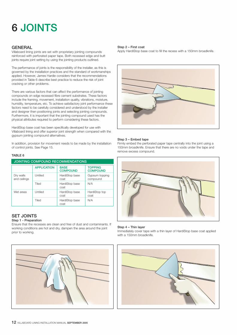
Step 2 – First coatApply HardiStop base coat to fill the recess with a 150mm broadknife.
Step 3 – Embed tapeFirmly embed the perforated paper tape centrally into the joint using a150mm broadknife. Ensure that there are no voids under the tape andremove excess compound.
Step 4 – Thin layerImmediately cover tape with a thin layer of HardiStop base coat appliedwith a 150mm broadknife.
6 JOINTS
GENERALVillaboard lining joints are set with proprietary jointing compoundsreinforced with perforated paper tape. Both recessed edge and buttjoints require joint setting by using the jointing products outlined.
The performance of joints is the responsibility of the installer, as this isgoverned by the installation practices and the standard of workmanshipsapplied. However, James Hardie considers that the recommendationsprovided in Table 6 describe best practice to reduce the risk of jointcracking or other problems.
There are various factors that can affect the performance of jointingcompounds on edge recessed fibre cement substrates. These factorsinclude the framing, movement, installation quality, vibrations, moisture,humidity, temperature, etc. To achieve satisfactory joint performance thesefactors need to be carefully considered and understood by the installerand designer then positioning joints and selecting jointing compounds.Furthermore, it is important that the jointing compound used has thephysical attributes required to perform considering these factors.
HardiStop base coat has been specifically developed for use withVillaboard lining and offer superior joint strength when compared with thegypsum jointing compound alternatives.
In addition, provision for movement needs to be made by the installationof control joints. See Page 15.
TABLE 6
SET JOINTSStep 1 - PreparationEnsure that the recesses are clean and free of dust and contaminants. Ifworking conditions are hot and dry, dampen the area around the jointprior to working.
JOINTING COMPOUND RECOMMENDATIONS
APPLICATION BASE TOPPINGCOMPOUND COMPOUND
Dry walls Untiled HardiStop base Gypsum toppingand ceilings coat compound
Tiled HardiStop base N/Acoat
Wet areas Untiled HardiStop base HardiStop topcoat coat
Tiled HardiStop base N/Acoat

VILLABOARD LINING INSTALLATION MANUAL SEPTEMBER 2005 13
Step 8 - Finishing coat Ensure the second coat is fully dry. Using a finishing trowel, apply asecond coat of topping compound 280mm wide centrally over the jointand feather out the edges. Allow to dry fully before sanding.
Step 9 – Fastener heads Ensure the second coat is fully dry.Apply a finishing coat of topping compound to fastener heads, featheringout the edges. Allow to fully dry before sanding.
Step 5 – Fastener headsCover all fastener heads with HardiStop base coat. Allow to dry beforeapplying a second coat.
NOTE: Steps 6-9 are not required for tiled walls.
Step 6 – Second coat When the base coat is fully dry, use a 200mm wide second coat trowelto apply the HardiStop base coat. Apply this coat approximately 180mmwide, laid down over the recess and feather the edges.
Step 7 – Fastener heads Ensure the base coat is fully dry. Apply a second coat over fastenerheads using the HardiStop base coat, overlapping the first by a minimumof 25mm. Allow to dry before applying finishing coat.

Step 4 – Thin layer (untiled walls only)Immediately cover tape with a thin layer of HardiStop base coat appliedwith a 150mm broadknife.
NOTE: Steps 5 and 6 are not required for tiled walls.
Step 5 – Second CoatWhen the first coat is fully dry, use a 200mm wide second coat trowel toapply the topping compound. Apply this coat approximately 300mm wide.
Step 6 - Finishing CoatEnsure the second coat is fully dry. Using a finishing trowel, apply a coatof topping compound 500mm wide centrally over the joint and featherout the edges. Allow to fully dry before sanding.
14 VILLABOARD LINING INSTALLATION MANUAL SEPTEMBER 2005
BUTT JOINTSStep 1 - PreparationWhen jointing un-recessed sheet joint, ensure that sheet edges are cleanand free of dust and contaminants. If working conditions are hot and dry,dampen the area around the joint prior to working.
Step 2 – First Coat Apply HardiStop base coat centrally over butt joint to 200mm wide with a150mm broadknife.
Step 3 – Embed tapeFirmly embed the perforated paper tape centrally using a 150mm broadknife. Ensure that there are no voids under the tape and removeexcess compound.

CONTROL JOINTSControl joints are required in long runs of Villaboard lining walls or ceilingsin either direction. These joints are designed to take up the structuralmovement between the sheets and the building frame. They may also berequired in ceilings where they change direction or continue into passageways. Control joints should also be provided at frame junctions/jointssuch as wall intersections.
See Table 7 for maximum control joint spacings and Figure 16 for atypical detail.
TABLE 7
Horizontal control joints in walls are required at 3.6 maximum centres.When sheeting vertically a horizontal control joint is required at the sheetend when using sheets shorter than 3.6m in length.
VILLABOARD LINING INSTALLATION MANUAL SEPTEMBER 2005 15
INTERNAL CORNERS Setting of internal corners are required for untiled applications only asfollows:
� Apply bedding compound to both sides of the corner using a 70mmbroadknife.
� Fold paper tape to form an angle and embed into the corner using a100mm corner tool and cover with a skim coat.
� Allow tape coat to dry, then apply a thin finishing coat by layingadditional compound over the angle and smoothing with the corner tool.
� Allow to fully dry before sanding
EXTERNAL CORNERSSetting of external corners is required for untiled applications only asfollows:
� Fit a perforated corner angle over the external corner angle and ensurestraightness before fixing with fibre cement nails at 300mm centres.
� Apply bedding compound to both sides of the corner angle to a widthof 150mm using a broadknife. Allow to dry before applying a second coat.
� Using a straight trowel, build up the edges to 250mm from the corner.Allow to dry.
� When dry, use the straight trowel to apply a thin finishing coat, 300mmwide, to both sides of the corner angle, feathering out the edges.
� Allow to fully dry before sanding.
MAXIMUM SPACING FOR CONTROL JOINTS (m)
STEEL FRAMING TIMBER FRAMING
Greater than0.55 - 0.75mm BMT 0.8 - 1.6mm BMT
General 9.0 6.0 7.2
Tiled walls 4.8 4.2
FIGURE 16 CONTROL JOINT
Villaboardlining
Adhesive
Ceramic tiles
Sealant
6mmmin.
Steel stud
Villaboard lining
Tiled
Untiled
Backing rod
15mmmin. gap
Foam tape insertin purpose mademovement jointaccessory e.gRondo P35
Plastic insertremoved aftersetting joint

16 VILLABOARD LINING INSTALLATION MANUAL SEPTEMBER 2005
7 FINISHES AND MAINTENANCE
GENERALVillaboard lining is finished with either paint, tiles or wallpaper as required.The application and maintenance of these finishes must be in accordancewith the manufacturer’s specifications.
NOTES1. For wet areas, the waterproofing requirements of all relevant codes,
standards and regulations must be met. For more information on wetarea construction refer to the James Hardie Wet area constructionDesign Manual.
2. Refer to the manufacturers’ specifications on application,compatibility and suitability of waterproofing membranes.
GLANCING LIGHTIn some instances, due to glancing light, set joints may be noticeable inVillaboard lining walls, especially where paint finishes have a high glosslevel. Work closely with your builder or designer to minimise this.
TABLE 8
Artificial lighting needs to be considered in relation to walls and ceilings(e.g. down-lights in ceilings above set joints in walls). Ceilings and walljoints should run in the direction of the light source (at right angles towindows).
Where glancing light is an issue its effect can be lessened by:
� The use of curtains or blinds.� Artificial light shading devices.� The use of light coloured, matt finish paints.
LEVEL OF FINISHESDifferent levels of finishes are typically specified for different applications.Higher levels of finishes are used to address the glancing light issues withpainted Villaboard lining referred to above. A description of the variouslevels of finishes and the jointing/coating requirements can be found inTable 8.
LEVELS OF FINISHES
LEVEL OF DEFINITION* TYPICAL JOINTING/SETTING FINISHFINISH
0 This level of finish may be useful in temporary No stopping, taping, finishing or accessories For use in areas where finishing and stoppingconstruction. are required. The work is confined to gluing is not considered necessary.
or screwing/nailing sheets in place.
1 For use in plenum areas above ceilings, in Joints and corner joints will be set with Surface free from excess jointing compound.areas where the work would generally be HardiStop bedding compound reinforced with Tool marks and ridges are generallyconcealed, or in building service corridors and perforated paper tape. acceptable.other areas not normally open to public view.
2 For use in warehouse, storage or other areas Joints and corner joints will be set with Minor tool marks and ridges are generallywhere surface appearance is not of primary HardiStop bedding compound reinforced with acceptable.concern. perforated paper tape and gypsum topping
compounds.
3 For use in areas which are to receive heavy Joints and corner joints will be set with This level of finish must be sufficiently smoothor medium texture (spray or hand applied) HardiStop bedding compound reinforced with to accept vinyl, tiles or textured coatingsfinishes or where heavy wall coverings paper perforated paper tape and gypsum topping without blemishes.are to be applied as the final decoration. This compounds.level of finish is not generally suitable wheresmooth painted surfaces or light to mediumwall coverings are specified.
4 This is generally the accepted level of finish Refer to flush jointing recommendations on For use where light-texture coatings or for domestic construction. It is used where page 11. wallpaper or other lightweight wall coveringslight textures or wall coverings and smooth are to be applied. For painted finishes in textured finishes and satin/flat/low sheen non-critical lighting areas flat and low-sheenpaints are illuminated by non-critical lighting. textured paints are to be applied. Gloss and
semi-gloss paints are not generally suitableover this level of finish as any minor blemishwill show under critical light.
The weight, texture and sheen level or wallcoverings applied over this level of finish mustbe carefully evaluated. Joints and fasteners must be adequately concealed if the wall-covering material is lightweight, contains limited pattern, has a gloss finish, or any combination of these features is present.Unbacked vinyl wall coverings are not suitableover this level of finish.
5 This level of finish is for use where gloss or Typically all joints and corner joints will have This level of finish is for use where gloss,semi-gloss paints are specified or where tape embedded in HardiStop bedding semi-gloss, low-sheen or non-textured paintscritical lighting conditions occur on satin, flat compound applied over all joints, angles, are specified or where critical lightingor low sheet paints. fastener heads and accessories. conditions occur.
A thin skim coat of finishing compound mustbe applied to the entire surface to be plastered.The surface must be finished smooth and freeof tool marks and ridges and special care mustbe taken with the application of the finishingcompound to achieve a smooth, true surfacesuitable for these critical finishes.
*Reference: AS/NZS 2589.1:1997 ‘Gypsum lining in residential and light commercial construction - Application and finishing. Part 1: Gypsum plasterboard’

PAINT FINISHESPrior to application of paint finishes, remove any residual sanding dustand ensure the surface is suitable for paint application.
Always follow the paint manufacturer’s recommendations for paintsuitability, mixing and application.
NOTEUse of a ‘sealer coat’ or ‘preparation undercoat’ is recommended.
CORNICESIt is recommended that Villaboard lining is wetted with a sponge prior toadhesive fixing of cornices.
TILED FINISHESThe thicknesses of tiles used over Villaboard lining are restricted basedon stud centres and the thickness of the sheet, see Table 9.
James Hardie only recommends the use of flexible tile adhesive for tileapplication. Refer to adhesive manufacturer for suitability and applicationinformation.
NOTES1. Do not tile ceilings.2. Do not tile to walls over 3m in height.
TABLE 9
*Support angles are recommended.The suitability and positioning of support angles is to be determined by astructural engineer. Support angles need to be fixed into the supportingframe and the overall wall mass and stability needs to be considered.
MAINTENANCEJames Hardie recommends that the cleaning and maintenance of allfinishes be undertaken regularly as per the recommendations of themanufacturer. Joints must also be maintained and be free of dirt and grime.
VILLABOARD LINING INSTALLATION MANUAL SEPTEMBER 2005 17
MAXIMUM TILE THICKNESSES
VILLABOARD MAXIMUM TILE THICKNESS (mm)THICKNESS (mm)
600mm Stud Cts 450mm Stud Cts
6 9 13
9 13 18
12 18* >25*
8 PRODUCTINFORMATION
GENERALVillaboard lining is a cellulose fibre reinforced cement building product.The basic composition is Portland cement, ground sand, cellulose fibreand water.
Villaboard lining is manufactured to AS/NZS 2908.2 ’Cellulose-CementProducts Part 2: Flat Sheets’ (ISO 8336 ‘Fibre Cement Flat Sheets’).
Villaboard lining is classified Type B, Category 3 in accordance withAS/NZS 2908.2.
For Material Safety Data Sheets (MSDS) visit www.jameshardie.com.au orAsk James Hardie™ on 13 11 03.
PRODUCT MASSBased on equilibrium moisture content the approximate mass ofVillaboard lining is:
� 6mm thick - 8.3kg/m2
� 9mm thick - 12.4kg/m2
� 12mm thick - 16.6kg/m2
DURABILITYResistance to moisture/rottingVillaboard lining has demonstrated resistance to permanent moistureinduced deterioration (rotting) by passing the following tests inaccordance with AS/NZS 2908.2:
� Water permeability (Clause 8.2.2)� Warm water (Clause 8.2.4)� Heat rain (Clause 6.5)� Soak dry (Clause 8.2.5)
Resistance to FireVillaboard lining is suitable where non-combustible materials are requiredin accordance with C1.12 of the Building Code of Australia.
Villaboard lining has been tested by CSIRO and is classified as a Group 1material in accordance with Specification C1.10a of the BCA.
Villaboard lining has the following early fire hazard indices (tested to AS 1530 Part 3).
Resistance to termite attackBased on testing completed by CSIRO Division of Forest ProductsReport Numbers FP349 and FP274, James Hardie fibre cement hasdemonstrated resistance to termite attack.
EARLY FIRE HAZARD INDICES
Ignition index 0
Flame spread index 0
Heat evolved index 0
Smoke developed index 0 - 1

18 VILLABOARD LINING INSTALLATION MANUAL SEPTEMBER 2005
NOTES

VILLABOARD LINING INSTALLATION MANUAL SEPTEMBER 2005 19
9 WARRANTY
James Hardie Australia Pty Limited ("James Hardie") warrants for a periodof 10 years from the date of purchase that the Villaboard® lining (the"Product"), will be free from defects due to defective factory workmanshipor materials and, subject to compliance with the conditions below, will beresistant to cracking, rotting, fire and damage from termite attacks to theextent set out in James Hardie’s relevant published literature current at thetime of installation. James Hardie warrants for a period of 12 months fromthe date of purchase that the accessories supplied by James Hardie willbe free from defects due to defective factory workmanship or materials.
Nothing in this document shall exclude or modify any legal rights acustomer may have under the Trade Practices Act or otherwise whichcannot be excluded or modified at law.
CONDITIONS OF WARRANTYThe warranty is strictly subject to the following conditions:
a) James Hardie will not be liable for breach of warranty unless theclaimant provides proof of purchase and makes a written claim eitherwithin 30 days after the defect would have become reasonablyapparent or, if the defect was reasonably apparent prior toinstallation, then the claim must be made prior to installation;
b) this warranty is not transferable;
c) the Product must be installed and maintained strictly in accordancewith the relevant James Hardie literature current at the time ofinstallation and must be installed in conjunction with the componentsor products specified in the literature. Further, all other products,including coating and jointing systems, applied to or used inconjunction with the Product must be applied or installed andmaintained strictly in accordance with the relevant manufacturer’sinstructions and good trade practice;
d) the project must be designed and constructed in strict compliancewith all relevant provisions of the current BCA, regulations andstandards;
e) the claimant’s sole remedy for breach of warranty is (at JamesHardie’s option) that James Hardie will either supply replacementproduct, rectify the affected product or pay for the cost of thereplacement or rectification of the affected product;
f) James Hardie will not be liable for any losses or damages (whetherdirect or indirect) including property damage or personal injury,consequential loss, economic loss or loss of profits, arising incontract or negligence or howsoever arising. Without limiting theforegoing James Hardie will not be liable for any claims, damages ordefects arising from or in any way attributable to poor workmanship,poor design or detailing, settlement or structural movement and/ormovement of materials to which the Product is attached, incorrectdesign of the structure, acts of God including but not limited toearthquakes, cyclones, floods or other severe weather conditions orunusual climatic conditions, efflorescence or performance ofpaint/coatings applied to the Product, normal wear and tear, growthof mould, mildew, fungi, bacteria, or any organism on any Productsurface or Product (whether on the exposed or unexposed surfaces);
g) all warranties, conditions, liabilities and obligations other than thosespecified in this warranty are excluded to the fullest extent allowed by law;
h) if meeting a claim under this warranty involves re-coating ofProducts, there may be slight colour differences between the originaland replacement Products due to the effects of weathering andvariations in materials over time.
DISCLAIMERThe recommendations in James Hardie’s literature are based on goodbuilding practice, but are not an exhaustive statement of all relevantinformation and are subject to conditions (c), (d), (f) and (g) above.Further, as the successful performance of the relevant system dependson numerous factors outside the control of James Hardie (eg quality ofworkmanship and design) James Hardie shall not be liable for therecommendations in that literature and the performance of the relevantsystem, including its suitability for any purpose or ability to satisfy therelevant provisions of the Building Code of Australia ("BCA"), regulationsand standards.

COPYRIGHT SEPTEMBER 2005© JAMES HARDIE AUSTRALIA PTY LTD ABN 12 084 635 558TM AND ® DENOTES A TRADEMARK OR REGISTERED MARKOWNED BY JAMES HARDIE INTERNATIONAL FINANCE BV.


![02- Sr[1]. John Shelford June 21 20053](https://img.pdfslide.us/doc/110x75/577cddc31a28ab9e78adac15/02-sr1-john-shelford-june-21-20053.jpg)