Embed Size (px)
Citation preview
DUCTLESS INVERTER
INSTALLATION MANUAL
Models:
AIR CONDITIONER
RIO09AC115V1ARIO12AC115V1ARIO09AC230V1ARIO12AC230V1A
RIO24AC230V1ARIO18AC230V1A
1
Thank you for choosing a
for your customer.
Please read this installation manual carefully before installing and starting up the Rio System. Take a moment to fill out the product and installation form on the back cover. Retain both the manual and installation record for future reference.
Contents
• Safety Precautions 2• System Requirements 4• Suggested Tools 5• Site Instructions 6• Dimensions 7• Indoor Unit 9• Outdoor Unit 12• Refrigerant Piping 13• Power and Wiring 16• Vacuum Testing 19• Start-up 21• Troubleshooting 22
Gree Rio Ductless AIR CONDITIONER
2
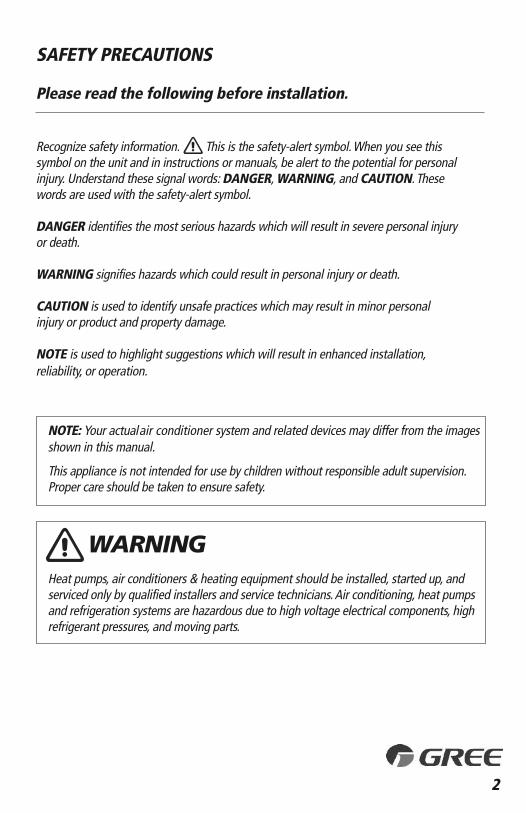
SAFETY PRECAUTIONS
Please read the following before installation.
Recognize safety information. This is the safety-alert symbol. When you see thissymbol on the unit and in instructions or manuals, be alert to the potential for personalinjury. Understand these signal words: DANGER, WARNING, and CAUTION. Thesewords are used with the safety-alert symbol.
DANGER identifies the most serious hazards which will result in severe personal injuryor death.
WARNING signifies hazards which could result in personal injury or death.
CAUTION is used to identify unsafe practices which may result in minor personal injury or product and property damage.
NOTE is used to highlight suggestions which will result in enhanced installation, reliability, or operation.
shown in this manual.
This appliance is not intended for use by children without responsible adult supervision.Proper care should be taken to ensure safety.
Heat pumps, air conditioners & heating equipment should be installed, started up, andserviced only by qualified installers and service technicians. Air conditioning, heat pumpsand refrigeration systems are hazardous due to high voltage electrical components, highrefrigerant pressures, and moving parts.
WARNING
NOTE: Your actual air conditioner system and related devices may differ from the images
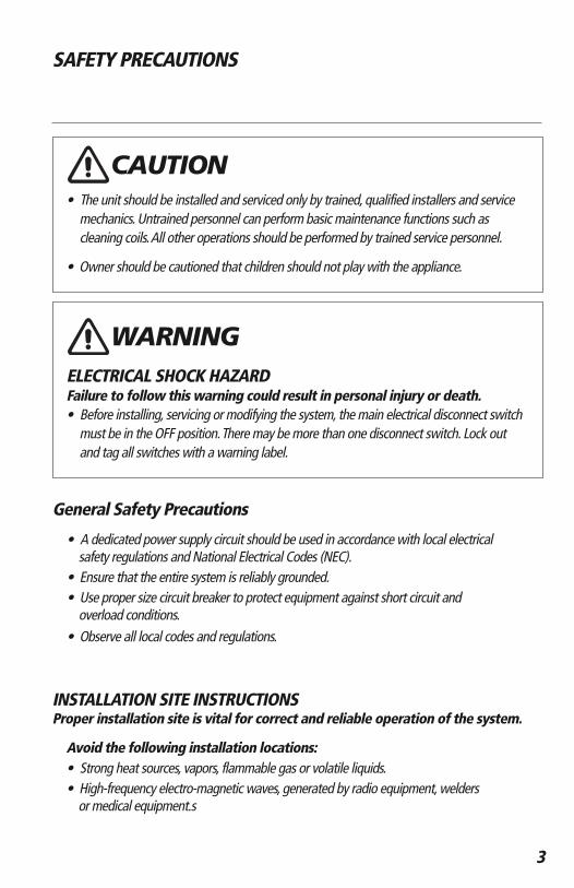
SAFETY PRECAUTIONS
• The unit should be installed and serviced only by trained, qualified installers and service mechanics. Untrained personnel can perform basic maintenance functions such as cleaning coils. All other operations should be performed by trained service personnel.
• Owner should be cautioned that children should not play with the appliance.
ELECTRICAL SHOCK HAZARDFailure to follow this warning could result in personal injury or death.• Before installing, servicing or modifying the system, the main electrical disconnect switch
must be in the OFF position. There may be more than one disconnect switch. Lock out and tag all switches with a warning label.
General Safety Precautions
• A dedicated power supply circuit should be used in accordance with local electrical safety regulations and National Electrical Codes (NEC).
• Ensure that the entire system is reliably grounded.• Use proper size circuit breaker to protect equipment against short circuit and
overload conditions.• Observe all local codes and regulations.
INSTALLATION SITE INSTRUCTIONSProper installation site is vital for correct and reliable operation of the system.
Avoid the following installation locations :• Strong heat sources, vapors, flammable gas or volatile liquids. • High-frequency electro-magnetic waves, generated by radio equipment, welders
or medical equipment.s
3
WARNING
CAUTION
4
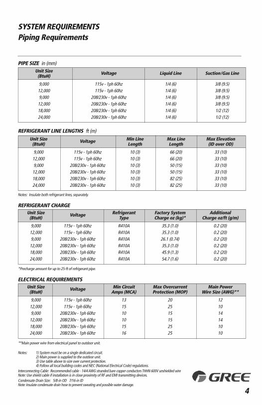
SYSTEM REQUIREMENTSPiping Requirements
REFRIGERANT CHARGE
ELECTRICAL REQUIREMENTS
PIPE SIZE in (mm)
Notes: Insulate both refrigerant lines, separately.
Notes: 1) System must be on a single dedicated circuit.2) Main power is supplied to the outdoor unit.3) Use table above to size over current protection.4) Follow all local building codes and NEC (National Electrical Code) regulations.
Interconnecting Cable: Recommended cable - 14/4 AWG stranded bare copper conductors THHN 600V unshielded wireNote: Use shield cable if installation is in close proximity of RF and EMI transmitting devices.Condensate Drain Size: 5/8-in OD 7/16-in IDNote: Insulate condensate drain hose to prevent sweating and possible water damage.
Unit Size Voltage Liquid Line Suction/Gas Line(BtuH)
9,000 115v - 1ph 60hz 1/4 (6) 3/8 (9.5)12,000 115v - 1ph 60hz 1/4 (6) 3/8 (9.5)9,000 208/230v - 1ph 60hz 1/4 (6) 3/8 (9.5)12,000 208/230v - 1ph 60hz 1/4 (6) 3/8 (9.5)18,000 208/230v - 1ph 60hz 1/4 (6) 1/2 (12)24,000 208/230v - 1ph 60hz 1/4 (6) 1/2 (12)
Unit Size Voltage Min Line Max Line Max Elevation(BtuH) Length Length (ID over OD)
9,000 115v - 1ph 60hz 10 (3) 66 (20) 33 (10)12,000 115v - 1ph 60hz 10 (3) 66 (20) 33 (10)9,000 208/230v - 1ph 60hz 10 (3) 50 (15) 33 (10)12,000 208/230v - 1ph 60hz 10 (3) 50 (15) 33 (10)18,000 208/230v - 1ph 60hz 10 (3) 82 (25) 33 (10)24,000 208/230v - 1ph 60hz 10 (3) 82 (25) 33 (10)
**Main power wire from electrical panel to outdoor unit.
*Precharge amount for up to 25-ft of refrigerant pipe.
REFRIGERANT LINE LENGTHS ft (m)
Unit Size Voltage Refrigerant Factory System Additional (BtuH) Type Charge oz (kg)* Charge oz/ft (g/m)
9,000 115v - 1ph 60hz R410A 35.3 (1.0) 0.2 (20)12,000 115v - 1ph 60hz R410A 35.3 (1.0) 0.2 (20)9,000 208/230v - 1ph 60hz R410A 26.1 (0.74) 0.2 (20)12,000 208/230v - 1ph 60hz R410A 35.3 (1.0) 0.2 (20)18,000 208/230v - 1ph 60hz R410A 45.9 (1.3) 0.2 (20)24,000 208/230v - 1ph 60hz R410A 54.7 (1.6) 0.2 (20)
Unit Size Voltage Min Circuit Max Overcurrent Main Power(BtuH) Amps (MCA) Protection (MOP) Wire Size (AWG)**
9,000 115v - 1ph 60hz 13 20 1212,000 115v - 1ph 60hz 15 25 109,000 208/230v - 1ph 60hz 10 15 1412,000 208/230v - 1ph 60hz 10 15 1418,000 208/230v - 1ph 60hz 15 25 1024,000 208/230v - 1ph 60hz 16 25 10
5
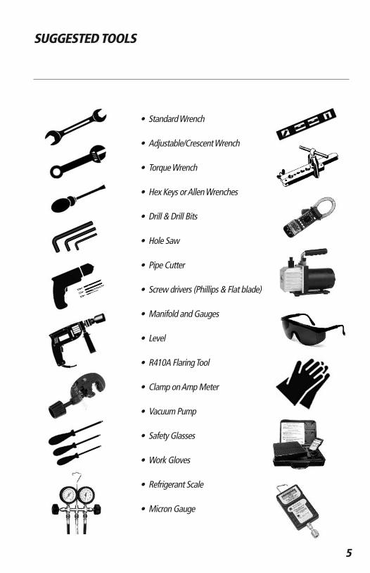
• Standard Wrench
• Adjustable/Crescent Wrench
• Torque Wrench
• Hex Keys or Allen Wrenches
• Drill & Drill Bits
• Hole Saw
• Pipe Cutter
• Screw drivers (Phillips & Flat blade)
• Manifold and Gauges
• Level
• R410A Flaring Tool
• Clamp on Amp Meter
• Vacuum Pump
• Safety Glasses
• Work Gloves
• Refrigerant Scale
• Micron Gauge
SUGGESTED TOOLS
6
INSTALLATION SITE INSTRUCTIONS
Step 1Installation Site of Indoor Unit
Select a site that allows for the following:• Ensure the installation complies with the installation minimum dimensions and meets the
minimum and maximum connecting piping length and maximum change in elevation.• Air inlet and outlet will be clear of obstructions, ensuring proper airflow throughout the room.• Condensate can be easily and safely drained.• All connections can be easily made to outdoor unit.• Indoor unit is out of reach of children.• A wall strong enough to withstand the full weight and vibration of the unit.• Filter can be easily accessed for cleaning.• Leave enough free space to allow access for routine maintenance. • Install at least 10 ft. (3 m) away from the antenna of TV set or radio. Operation of the air
conditioner may interfere with radio or TV reception in areas where reception is weak. An amplifier may be required for the affected device.
• Do not install in a laundry room or by a swimming pool.
Installation Site of Outdoor Unit
Select a site that allows for the following:• Outdoor location meets all minimum installation distances defined in the Installation
Dimensions section. • Sound from outdoor unit will not annoy neighbors.• All connections can be easily made to indoor unit.• Air inlet and outlet will be clear of obstructions to ensure proper airflow.• Wall or roof is strong enough to withstand the full weight and vibration of the outdoor
unit (for wall or roof installation only).• Outdoor unit is out of reach of children and does not obstruct walkways.• Outdoor unit is not exposed to direct sunlight or strong wind.• Maintenance and repairs can be easily performed on the outdoor unit.• Ensure the installation complies with the minimum and maximum connecting piping
length and maximum change in elevation criteria.
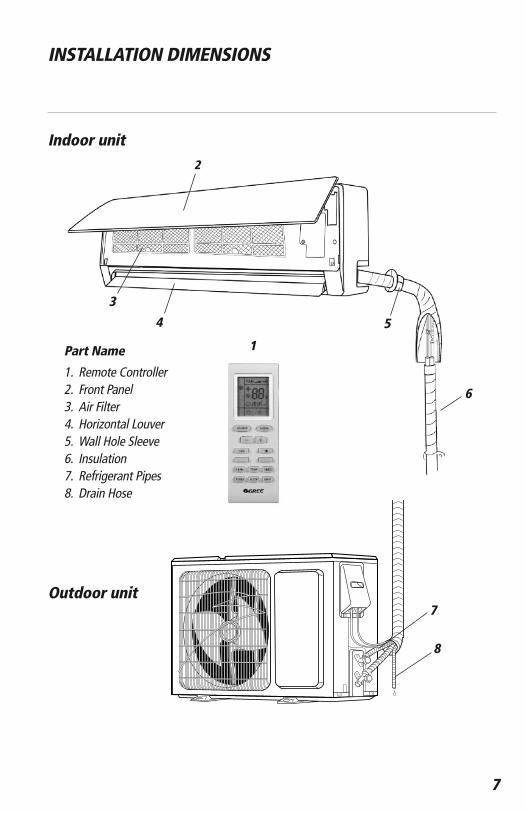
Indoor unit
Part Name
1. Remote Controller2. Front Panel3. Air Filter4. Horizontal Louver5. Wall Hole Sleeve6. Insulation7. Refrigerant Pipes8. Drain Hose
Outdoor unit
2
3
6
5
8
7
4
1
7
INSTALLATION DIMENSIONS
8
INSTALLATION DIMENSIONS
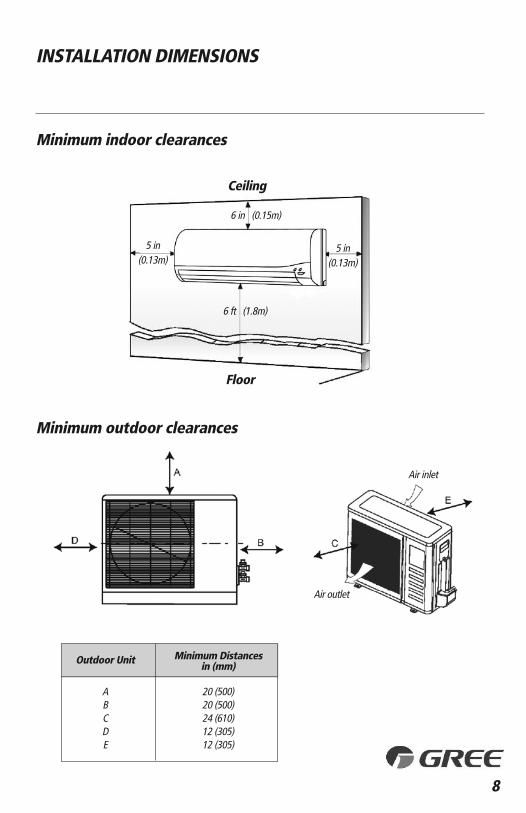
Minimum indoor clearances
Minimum outdoor clearances
Outdoor Unit Minimum Distances in (mm)
A 20 (500)B 20 (500)C 24 (610)D 12 (305)E 12 (305)
5 in(0.13m)
5 in(0.13m)
6 ft (1.8m)
6 in (0.15m)
Air inlet
Air outlet
Ceiling
Floor
9
INSTALLATION OF INDOOR UNIT
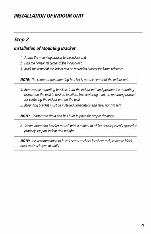
Step 2
Installation of Mounting Bracket
1. Attach the mounting bracket to the indoor unit. 2. Find the horizontal center of the indoor unit. 3. Mark the center of the indoor unit on mounting bracket for future reference.
NOTE: The center of the mounting bracket is not the center of the indoor unit.
4. Remove the mounting brackets from the indoor unit and position the mountingbracket on the wall in desired location. Use centering mark on mounting bracket for centering the indoor unit on the wall.
5. Mounting bracket must be installed horizontally and level right to left.
NOTE: Condensate drain pan has built-in pitch for proper drainage.
6. Secure mounting bracket to wall with a minimum of five screws, evenly spaced toproperly support indoor unit weight.
NOTE: It is recommended to install screw anchors for sheet rock, concrete block, brick and such type of walls.
10
INSTALLATION OF INDOOR UNIT
39 5/8
27
22 5/8
5 1/8 7 1/2
171
5 3/
4
3 1/2
2 3/4 2 3/4
1 1/2
2 3/4
1 3/
4
12 1
/2
3421 3/8 5 3/4
17 3
/4
8 1/83/41/2 4 1/2 5 1/2
1 1/2
2 3/42 3/4
Φ2 1/4Φ2 1/4
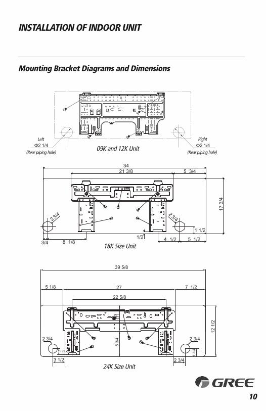
Mounting Bracket Diagrams and Dimensions
09K and 12K Unit
18K Size Unit
24K Size Unit
Right
(Rear piping hole)
Left
(Rear piping hole)
11
INSTALLATION OF INDOOR UNIT
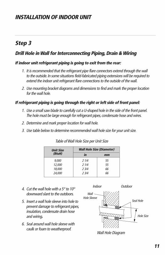
Step 3
Drill Hole in Wall for Interconnecting Piping, Drain & Wiring
Seal Hole
Hole Size
Indoor Outdoor
If indoor unit refrigerant piping is going to exit from the rear:
1. It is recommended that the refrigerant pipe flare connectors extend through the wall to the outside. In some situations field-fabricated piping extensions will be required to extend the indoor unit refrigerant flare connections to the outside of the wall.
2. Use mounting bracket diagrams and dimensions to find and mark the proper location for the wall hole.
If refrigerant piping is going through the right or left side of front panel:
1. Use a small saw blade to carefully cut a U-shaped hole in the side of the front panel. The hole must be large enough for refrigerant pipes, condensate hose and wires.
2. Determine and mark proper location for wall hole.
3. Use table below to determine recommended wall hole size for your unit size.
4. Cut the wall hole with a 5° to 10° downward slant to the outdoors.
5. Insert a wall hole sleeve into hole to prevent damage to refrigerant pipes, insulation, condensate drain hose and wiring.
6. Seal around wall hole sleeve with caulk or foam to weatherproof.
Wall Hole Sleeve
Wall Hole Diagram
Table of Wall Hole Size per Unit Size
Unit Size Wall Hole Size (Diameter)(BtuH) in mm
9,000 2 1/4 5512,000 2 1/4 5518,000 2 3/4 6624,000 2 3/4 66
Install Ground Pad or Wall Hangers
1. Determine proper location for outdoor unit.2. Follow all instructions provided by manufacturer for installing wall hangers or ground pad.3. Verify the wall hangers or ground pad can safely support the weight of the outdoor unit.4. Verify the wall hangers or ground pad is level and meets all outdoor dimensional clearances.
Install Outdoor Unit Risers
If the outdoor unit requires added elevation above the ground, installing riser legs will providea sturdy and stable solution. Follow all instructions provided by manufacturer for installing riser legs to outdoor unit.
NOTE: Riser legs will also help absorb vibrations and noise while facilitating proper drainage.
Florida Wind Load Requirements state that outdoor unit must be anchored to concrete pad using four 3/8-in diameter Power Wedge Bolt Plus (or equivalent)with 1-in diameter fender washers. Anchor bolts must be embedded into 3,000 PSI minimum concrete at a distance of 4 1/2-in from any concrete edge. The concrete thickness must exceed 1.5 times the anchor depth.
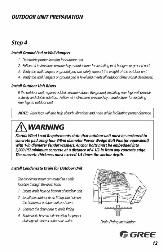
Install Condensate Drain for Outdoor Unit
location through the drain hose.
1. Locate drain hole on bottom of outdoor unit.
2. Install the outdoor drain fitting into hole onthe bottom of outdoor unit as shown.
3. Connect the drain hose to drain fitting.
4. Route drain hose to safe location for proper drainage of excess condensate water.
WARNING
12
OUTDOOR UNIT PREPARATION
Step 4
Drain Fitting Installation
The condenser water c an routed to a safe
13
INSTALLATION OF REFRIGERANT PIPING
Step 5
Piping Connections to Outdoor Unit
Use refrigeration grade tubing ONLY. No other type of tubing may be used. Use of other types of tubing will void manufacturer’s warranty. Make sure there is enough piping to cover the required length between the outdoor and indoor unit.
Piping Preparation
• Do not open service valves or remove protective caps from tubing ends until all connections are made.
• Keep tubing free of dirt, sand, moisture and contaminants.
• Insulate each refrigerant pipe and condensate hose with minimum 3/8” (10 mm) wall thermal pipe insulation.
NOTE: Insulate condensate hose to prevent sweating which may cause water stains or wall damage.
• Bind refrigerant pipes, condensate hose and interconnecting wire together with cable ties at 12 inch intervals.
Piping and Drain Hose Connections to Indoor Unit
NOTE: For maximum serviceability, it is recommended to have refrigerant pipe flare connections and the drain connection on the outside.
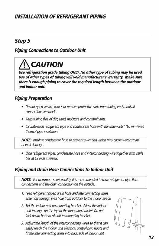
1. Feed refrigerant pipes, drain hose and interconnecting wires assembly through wall hole from outdoor to the indoor space.
2. Set the indoor unit on mounting bracket. Allow the indoorunit to hinge on the top of the mounting bracket. Do notlock down bottom of unit to mounting bracket.
3. Adjust the length of the interconnecting wires so that it can easily reach the indoor unit electrical control box. Route and fit the interconnecting wires into back side of indoor unit.
CAUTION
14
INSTALLATION OF REFRIGERANT PIPING
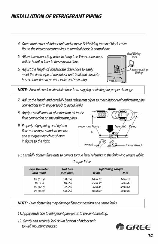
4. Open front cover of indoor unit and remove field wiring terminal block cover. Route the interconnecting wires to terminal block in control box.
5. Allow interconnecting wires to hang free. Wire connectionswill be handled later in these instructions.
6. Adjust the length of condensate drain hose to easilymeet the drain pipe of the indoor unit. Seal and insulatehose connection to prevent leaks and sweating.
NOTE: Prevent condensate drain hose from sagging or kinking for proper drainage.
7. Adjust the length and carefully bend refrigerant pipes to meet indoor unit refrigerant pipe connections with proper tools to avoid kinks.
8. Apply a small amount of refrigerant oil to theflare connection on the refrigerant pipes.
9. Properly align piping and tightenflare nut using a standard wrenchand a torque wrench as shown in figure to the right:
10. Carefully tighten flare nuts to correct torque level referring to the following Torque Table:
NOTE: Over tightening may damage flare connections and cause leaks.
11. Apply insulation to refrigerant pipe joints to prevent sweating.
12. Gently and securely lock down bottom of indoor unit to wall mounting bracket.
Pipe Diameter Nut Size Tightening Torque inch (mm) inch (mm) ft-lbs N-m
1/4 (6.35) 1/4 (17) 10 to 13 14 to 18 3/8 (9.5) 3/8 (22) 25 to 30 34 to 421/2 (12.7) 1/2 (25) 36 to 45 49 to 615/8 (15.9) 5/8 (29) 50 to 60 68 to 82
Torque Table
Field WiringCover
InterconnectingWiring
Indoor Unit Piping Taper Nut
Wrench Torque Wrench
Piping
15
INSTALLATION OF REFRIGERANT PIPING
Step 6
Piping Connections to Outdoor Unit
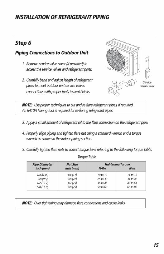
1. Remove service valve cover (if provided) toaccess the service valves and refrigerant ports.
2. Carefully bend and adjust length of refrigerant pipes to meet outdoor unit service valves connections with proper tools to avoid kinks.
NOTE: Use proper techniques to cut and re-flare refrigerant pipes, if required.An R410A Flaring Tool is required for re-flaring refrigerant pipes.
3. Apply a small amount of refrigerant oil to the flare connection on the refrigerant pipe.
4. Properly align piping and tighten flare nut using a standard wrench and a torque wrench as shown in the indoor piping section.
5. Carefully tighten flare nuts to correct torque level referring to the following Torque Table:
NOTE: Over tightening may damage flare connections and cause leaks.
Pipe Diameter Nut Size Tightening Torque inch (mm) inch (mm) ft-lbs N-m
1/4 (6.35) 1/4 (17) 10 to 13 14 to 18 3/8 (9.5) 3/8 (22) 25 to 30 34 to 421/2 (12.7) 1/2 (25) 36 to 45 49 to 615/8 (15.9) 5/8 (29) 50 to 60 68 to 82
Torque Table
Service Valve Cover

16
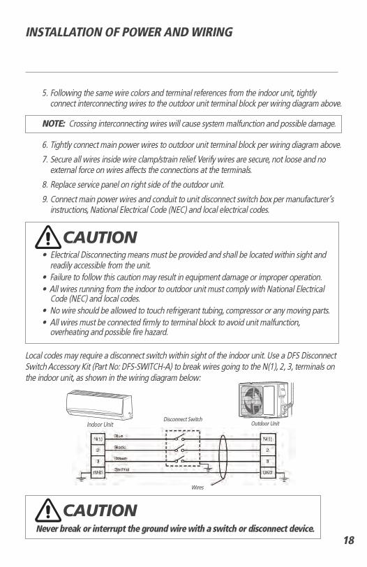
INSTALLATION OF POWER AND WIRING
Step 7
Indoor Unit Interconnecting Wire Connections
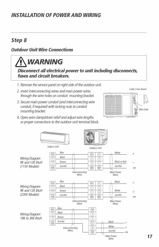
Disconnect all electrical power to unit including disconnects, fuses and circuit breakers.
1. Open front cover of indoor unit and remove field wiring terminal block cover.
2. Pull interconnecting wires up from back of indoor unit and position in close to the terminal block on indoor unit.
NOTE: The indoor unit is powered from the outdoor unit, depending on local code, a disconnect switch may need to be installed to a power supply circuit.
3. Connect wiring to indoor unit per connection diagram.
NOTE: Record wire colors and terminal references for uses with Outdoor Unit wire connections.
4. Replace field wiring cover and close front cover of indoor unit.
WARNING
VACUUM TESTING
Step 9Leaking Test
1. Connect the charging hose of the manifold valve to charge the end of the low-pressure valve.2. Add dry nitrogen to a pressure of 200 lbs. Tightly close both high- and low-pressure valves.3. Leak-test flare fittings with soap bubbles. If no leak is detected, release nitrogen.
Step 10System Vacuum and Charge
UNIT DAMAGE HAZARDNever use the system compressor as a vacuum pump. It may result in equipment damage or improper system operation.
Refrigerant pipes and indoor coil should be evacuated using the recommended deep vacuum method of 500 microns. The alternate triple evacuation method may be used if the procedure outlined below is followed.
NOTE: Alway break a vacuum with dry nitrogen.
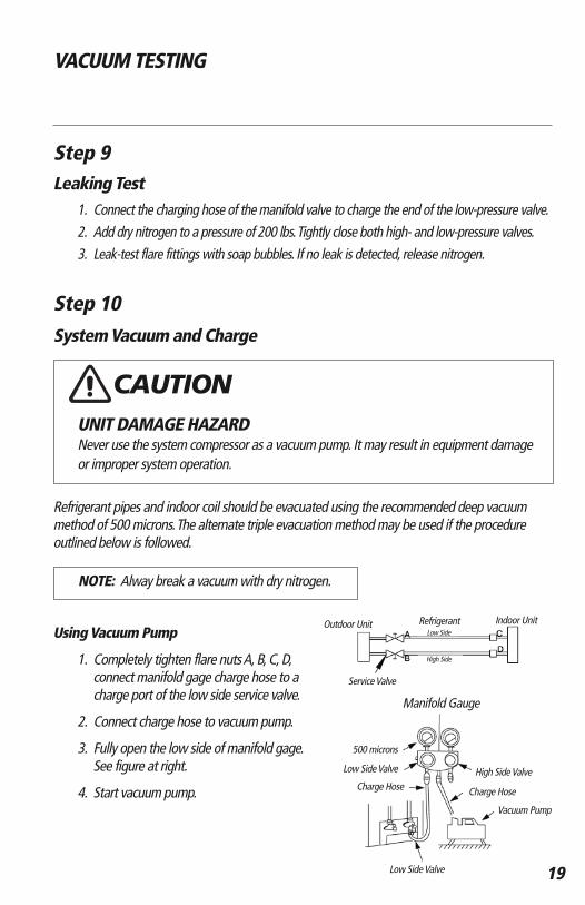
Using Vacuum Pump
1. Completely tighten flare nuts A, B, C, D, connect manifold gage charge hose to acharge port of the low side service valve.
2. Connect charge hose to vacuum pump.
3. Fully open the low side of manifold gage. See figure at right.
4. Start vacuum pump.
CAUTION
Manifold Gauge
19
Outdoor Unit
Service Valve
500 microns
Low Side Valve High Side Valve
Charge Hose
Vacuum Pump
Low Side Valve
Charge Hose
Refrigerant Indoor UnitLow Side
High Side
5. Evacuate using either deep vacuum or triple evacuation method.
6. After evacuation is complete, fully close the low side of manifold gage and stop operation of vacuum pump.
7. The factory charge contained in the outdoor unit is good for up to 25 ft. (8 m) of line length.
NOTE: For refrigerant lines longer than 25 ft (8 m), add add’l refrigerant per foot of extra piping up to the maximum allowable length. See System Requirement section on page 4 for more info
8. Disconnect charge hose from charge connection of the low side service valve.
9. Fully open service valves B and A.
10. Securely tighten caps of service valves.
20
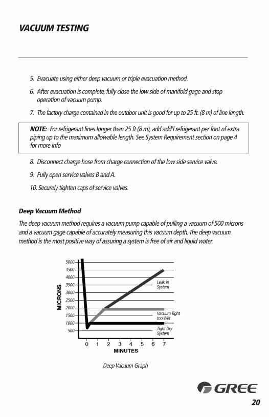
Deep Vacuum Method
The deep vacuum method requires a vacuum pump capable of pulling a vacuum of 500 micronsand a vacuum gage capable of accurately measuring this vacuum depth. The deep vacuummethod is the most positive way of assuring a system is free of air and liquid water.
VACUUM TESTING
Deep Vacuum Graph
5000
4500
4000
3500
3000
2500
2000
1500
1000
500
Leak inSystem
Vacuum Tighttoo Wet
Tight DrySystem
21
START-UP
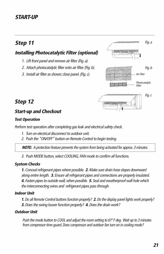
Step 11
Installing Photocatalytic Filter (optional)
1. Lift front panel and remove air filter. (Fig. a).
2. Attach photocatalytic filter onto air filter. (Fig. b).
3. Install air filter as shown; close panel. (Fig. c).
Step 12
Start-up and Checkout
Test Operation
Perform test operation after completing gas leak and electrical safety check.
1. Turn on electrical disconnect to outdoor unit.2. Push the “ON/OFF” button on Remote Control to begin testing.
NOTE: A protection feature prevents the system from being activated for approx. 3 minutes.
System Checks1. Conceal refrigerant pipes where possible. 2. Make sure drain hose slopes downward along entire length. 3. Ensure all refrigerant pipes and connections are properly insulated. 4. Fasten pipes to outside wall, when possible. 5. Seal and weatherproof wall hole which the interconnecting wires and refrigerant pipes pass through.
Indoor Unit1. Do all Remote Control buttons function properly? 2. Do the display panel lights work properly?3. Does the swing louver function properly? 4. Does the drain work?
Outdoor Unit
Push the mode button to COOL and adjust the room setting to 61°F deg. Wait up to 3 minutes from compressor time guard. Does compressor and outdoor fan turn on in cooling mode?
Fig. a
Air Filter
Photocatalytic Filter
Fig. b
Fig. c
3. Push MODE button, select COOLING, FAN mode to confirm all functions.
22
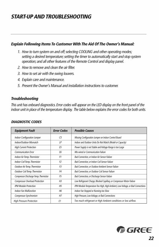
Troubleshooting
This unit has onboard diagnostics. Error codes will appear on the LED display on the front panel of theindoor unit in place of the temperature display. The table below explains the error codes for both units.
START-UP AND TROUBLESHOOTING
Explain Following Items To Customer With The Aid Of The Owner’s Manual:
setting a desired temperature; setting the timer to automatically start and stop system operation; and all other features of the Remote Control and display panel.
2. How to remove and clean the air filter.3. How to set air with the swing louvers.4. Explain care and maintenance.5. Present the Owner’s Manual and installation instructions to customer.
DIAGNOSTIC CODES
Equipment Fault
Indoor Configuration Jumper
Indoor/Outdoor Mismatch
High Current Protection
Communication Error
Indoor Air Temp. Thermistor
Indoor Coil Temp. Thermistor
Outdoor Air Temp. Thermistor
Outdoor Coil Temp. Thermistor
Compressor Discharge Temp. Thermistor
Compressor Overload Protection
IPM Module Protection
Indoor Fan Malfunction
Possible Causes
Missing Configuration Jumper on Indoor Control Board
Indoor and Outdoor Units Do Not Match (Model or Capacity)
Power Supply is not Stable and Voltage Range is too Large
Mis-wired or Communication Failure
Bad Connection, or Indoor Air Sensor Failure
Bad Connection, or Indoor Coil Sensor Failure
Bad Connection, or Outdoor Ambient Sensor Failure
Bad Connection, or Outdoor Coil Sensor Failure
Bad Connection, or Discharge Sensor Failure
Low Refrigerant Charge, Blocked Capillary, or Compressor Motor Failure
IPM Module Temperature Too High, High Ambient, Low Voltage, or Bad Connections
Indoor Fan Stopped or Running too Slow
High Pressure, Low Voltage, or Bad Connections
Error Codes
C5
LP
E5
E6
F1
F2
F3
F4
F5
H3
H5
H6
H7
1. How to turn system on and off; selecting COOLING and other operating modes;
Compressor Synchronism
High Pressure Protection E1 Too much refrigerant or High Ambient conditions or low airflow.
GREE ELECTRIC APPLIANCES, INC.
www.greecomfort.com
PRODUCT & INSTALLATION RECORD
For your convenience, please record the model and serial numbers of your new equipment in thespaces provided. This information, along with the installation data and dealer contact information, will be helpful should your system require maintenance or service.
UNIT INFORMATION
Model No.
Serial No.
INSTALLATION INFORMATION
Date Installed:
DEALERSHIP/INSTALLER INFORMATION
Company Name:
Address:
Phone Number:
Technician Name:
66129914820Gree Electric Appliances, Inc ©2014 Cat No: DFS-RIO-CO-2IN