Embed Size (px)
Citation preview

En-1
AIR CONDITIONER
PART No. 9380545101-02
Engl
ish
OUTDOOR UNIT
Fran
çais
Espa
ñol
APPAREIL EXTÉRIEURE
UNIDAD EXTERIOR
INSTALLATION MANUAL
For authorized service personnel only.
MANUEL D’INSTALLATION
MANUAL DE INSTALACIÓN
Seulement pour personnel d’entretien autorisé.
Únicamente para personal de servicio autorizado.
9380545101-02_IM.indb 19380545101-02_IM.indb 1 2/26/2016 10:16:02 AM2/26/2016 10:16:02 AM

En-1
1. SAFETY PRECAUTIONS
This installation manual describes how to install the outdoor unit only. To install the indoor unit, refer to the installation manual included with the indoor unit.
IMPORTANT!Please Read Before StartingThis air conditioning system meets strict safety and operating standards.As the installer or service person, it is an important part of your job to install or service the system so it operates safely and effi ciently.For safe installation and trouble-free operation, you must:• Carefully read this instruction booklet before beginning.• Follow each installation or repair step exactly as shown.• Observe all local, state, and national electrical codes.• Pay close attention to all warning, and caution notices given in this manual.
WARNING: This symbol refers to a hazard or unsafe practice which can result in severe personal injury or death.
CAUTION: This symbol refers to a hazard or unsafe practice which can result in personal injury and the potential for product or property damage.
• Hazard alerting symbols
Electrical
Safety / alert
If Necessary, Get HelpThese instructions are all you need for most installation sites and maintenance conditions. If you require help for a special problem, contact our sales/service outlet or your certifi ed dealer for additional instructions.In Case of Improper InstallationThe manufacturer shall in no way be responsible for improper installation or maintenance service, including failure to follow the instructions in this document.
SPECIAL PRECAUTIONS When Wiring ELECTRICAL SHOCK CAN CAUSE SEVERE PERSONAL INJURY OR DEATH. ONLY A QUALIFIED, EXPERIENCED ELECTRICIAN SHOULD ATTEMPT TO WIRE THIS SYSTEM.• Do not supply power to the unit until all wiring and tubing are completed or reconnected
and checked.• Highly dangerous electrical voltages are used in this system. Carefully refer to the wiring
diagram and these instructions when wiring. Improper connections and inadequate earthing (grounding) can cause accidental injury or death.
• Earth (Ground) the unit following local electrical codes.• Connect all wiring tightly. Loose wiring may cause overheating at connection points and
a possible fi re hazard.When Transporting Be careful when picking up and moving the indoor and outdoor units. Get a partner to help, and bend your knees when lifting to reduce strain on your back. Sharp edges or thin aluminum fi ns on the air conditioner can cut your fi ngers.When Installing... ...In a Ceiling or WallMake sure the ceiling/wall is strong enough to hold the unit’s weight. It may be necessary to construct a strong wood or metal frame to provide added support....In a RoomProperly insulate any tubing run inside a room to prevent “sweating” that can cause dripping and water damage to walls and fl oors....In Moist or Uneven LocationsUse a raised concrete pad or concrete blocks to provide a solid, level foundation for the outdoor unit. This prevents water damage and abnormal vibration....In an Area with High WindsSecurely anchor the outdoor unit down with bolts and a metal frame. Provide a suitable air baffl e....In a Snowy Area (for Heat Pump-type Systems)Install the outdoor unit on a raised platform that is higher than drifting snow. Provide snow vents.When Connecting Refrigerant Tubing • Keep all tubing runs as short as possible.• Use the fl are method for connecting tubing.• Apply refrigeration compressor oil (or equivalent) used for the outdoor unit to the matching
surfaces of the fl are and union tubes before connecting them, then tighten the nut with a torque wrench for a leak-free connection.
• Check carefully for leaks before opening the refrigerant valves.NOTE:Depending on the system type, liquid and gas lines may be either narrow or wide. Therefore, to avoid confusion the refrigerant tubing for your particular model is specifi ed as either “small” or “large” rather than as “liquid” or “gas”.When Servicing •Turn the power OFF at the main circuit breaker panel before opening the unit to check or
repair electrical parts and wiring.• Keep your fi ngers and clothing away from any moving parts.• Clean up the site after you fi nish, remembering to check that no metal scraps or bits of
wiring have been left inside the unit being serviced.• After installation, explain correct operation to the customer, using the operating manual.
• Be sure to read this Manual thoroughly before installation.• The warnings and precautions indicated in this Manual contain important information
pertaining to your safety. Be sure to observe them.• Hand this Manual, together with the Operating Manual, to the customer. Request the
customer to keep them on hand for future use, such as for relocating or repairing the unit.
WARNINGInstallation of this product must be done by experienced service technicians or profes-sional installers only in accordance with this manual. Installation by nonprofessional or improper installation of the product may cause serious accidents such as injury, water leakage, electric shock, or fi re. If the product is installed in disregard of the instructions in this manual, it will void the manufacturer’s warranty.
Never touch electrical components immediately after the power supply has been turned off. Electrical shock may occur. After turning off the power, always wait 10 minutes or more before touching electrical components.
Do not turn ON the power until all work has been completed. Turning ON the power before the work is completed can cause serious accidents such as electric shock or fi re.
If refrigerant leaks while work is being carried out, ventilate the area. If the refrigerant comes in contact with a fl ame, it produces a toxic gas.
Installation must be performed in accordance with regulations, codes, or standards for electrical wiring and equipment in each country, region, or the installation place.
Do not use this equipment with air or any other unspecifi ed refrigerant in the refriger-ant lines. Excess pressure can cause a rupture.
During installation, make sure that the refrigerant pipe is attached fi rmly before you run the compressor. Do not operate the compressor under the condition of refrigerant piping not attached properly with 2-way or 3-way valve open. This may cause abnor-mal pressure in the refrigeration cycle that leads to breakage and even injury.
When installing and relocating the air conditioner, do not mix gases other than the specifi ed refrigerant (R410A) to enter the refrigerant cycle. If air or other gas enters the refrigerant cycle, the pressure inside the cycle will rise to an abnormally high value and cause breakage, injury, etc.
Contents1. SAFETY PRECAUTIONS ……………………………………………………………… 12. ABOUT THIS PRODUCT ………………………………………………………………… 2
2. 1. Precautions for using R410A refrigerant ………………………………………… 22. 2. Special tools for R410A refrigerant ……………………………………………… 22. 3. Accessories ………………………………………………………………………… 32. 4. System confi guration ……………………………………………………………… 3
3. GENERAL SPECIFICATIONS …………………………………………………………… 53. 1. Power ………………………………………………………………………………… 53. 2. Selecting circuit breaker and wiring ……………………………………………… 53. 3. Selecting the pipe material ………………………………………………………… 53. 4. Heat insulation around connection pipes requirements ………………………… 63. 5. Operating range …………………………………………………………………… 63. 6. Additional charging ………………………………………………………………… 6
4. INSTALLATION WORK ………………………………………………………………… 64. 1. Selecting an installation location ………………………………………………… 64. 2. Installation dimensions …………………………………………………………… 64. 3. Placing the unit ……………………………………………………………………… 74. 4. Drain installation …………………………………………………………………… 84. 5. Secure the unit ……………………………………………………………………… 8
5. PIPE INSTALLATION …………………………………………………………………… 85. 1. Pipe connection …………………………………………………………………… 85. 2. Sealing test ……………………………………………………………………… 105. 3. Vacuum process ………………………………………………………………… 10
6. ELECTRICAL WIRING ………………………………………………………………… 106. 1. Notes for electrical wiring ……………………………………………………… 116. 2. Connection diagrams …………………………………………………………… 116. 3. Wiring method …………………………………………………………………… 126. 4. Connecting the Central remote controller (Option) …………………………… 13
7. HOW TO OPERATE DISPLAY UNIT ………………………………………………… 137. 1. Various setting methods ………………………………………………………… 137. 2. Base heater forced off function ………………………………………………… 147. 3. Outdoor unit low noise operation function (option) …………………………… 14
8. CHECK RUN …………………………………………………………………………… 148. 1. Things to confi rm before starting the check run. ……………………………… 148. 2. Restrictions applicable when performing the check run ……………………… 148. 3. Operating procedure for check run …………………………………………… 158. 4. Check run judgment failure display …………………………………………… 178. 5. Re-display check run results …………………………………………………… 178. 6. Automatic wiring correction memory reset …………………………………… 17
9. TEST RUN ……………………………………………………………………………… 179. 1. TEST RUN method ……………………………………………………………… 17
10. ERROR CODE ………………………………………………………………………… 1810. 1. In the event of an error ……………………………………………………… 1810. 2. Error location display ……………………………………………………… 1810. 3. Error code display …………………………………………………………… 18
11. PUMP DOWN…………………………………………………………………………… 1812. CUSTOMER GUIDANCE ……………………………………………………………… 19
AIR CONDITIONERINSTALLATION MANUALPART No. 9380545101-02Outdoor Unit
9380545101-02_IM.indb 19380545101-02_IM.indb 1 2/26/2016 10:16:02 AM2/26/2016 10:16:02 AM

En-2
WARNINGTo connect the indoor unit and outdoor unit, use air conditioner piping and cables available locally as standard parts. This manual describes proper connections using such installation set.
If the supply cord is damaged, it must be replaced by the manufacturer, its service agent or similarly qualifi ed persons in order to avoid a hazard.
Do not modify power cable, use extension cable or branch wiring. Improper use may cause electric shock or fi re by poor connection, insuffi cient insulation or over current.
Do not purge the air with refrigerants but use a vacuum pump to vacuum the installa-tion.
There is not extra refrigerant in the outdoor unit for air purging.
Using the same vacuum pump for different refrigerants may damage the vacuum pump or the unit.
Use a clean gauge manifold, vacuum pump and charging hose for R410A exclusively.
During the pump down operation, make sure that the compressor is turned off before you remove the refrigerant piping.Do not remove the connection pipe while the compressor is in operation with 2 way or 3 way valve open. This may cause abnormal pressure in the refrigeration cycle that leads to rupture and even injury.
This appliance is not intended for use by persons (including children) with reduced physical, sensory or mental capabilities, or lack of experience and knowledge, unless they have been given supervision or instruction concerning use of the appliance by a person responsible for their safety. Children should be supervised to ensure that they do not play with the appliance.
To avoid danger of suffocation, keep the plastic bag or thin fi lm used as the packaging material away from young children.
When installing this system in high humidity locations, install using ground fault equip-ment breakers (often referred to in other countries as an ELCB [earth leakage current breaker]) to reduce the risk of leaking current which may result in electric shock or potential fi re.
CAUTIONRead carefully all safety information written in this manual before you install or use the air conditioner.
This unit must be installed by qualifi ed personnel with a capacity certifi cate for han-dling refrigerant fl uids. Refer to regulation and laws in use on installation place.
Installation work must be performed in accordance with national wiring standards by authorized personnel only.
Install the product by following local codes and regulations in force at the place of installation, and the instructions provided by the manufacturer.
Connect the indoor unit and outdoor unit with the air conditioner piping and cables available standards parts. This installation manual describes the correct connections using the installation set available from our standard parts.
Do not use an extension cable.
Do not turn on the power until all installation work is complete.
Do not purge the air with refrigerants but use a vacuum pump to vacuum the installa-tion.
There is not extra refrigerant in the outdoor unit for air purging.
Use a vacuum pump for R410A exclusively.
Using the same vacuum pump for different refrigerants may damage the vacuum pump or the unit.
Use a clean gauge manifold and charging hose for R410A exclusively.
After a long period of disuse in an environment 32 °F (0 °C) or lower, supply power to the unit at least 12 hours before re-starting the unit.
This product is part of a set constituting an air conditioner. The product must not be installed alone or be installed with non-authorized device by the manufacturer.
Always use a separate power supply line protected by a circuit breaker operating on all wires with a distance between contact of 3 mm for this product.
To protect the persons, earth (ground) the product correctly, and use the power cable combined with an Earth Leakage Circuit Breaker (ELCB).
This product is not explosion proof, and therefore should not be installed in explosive atmosphere.
Do not touch the fi ns of the heat exchanger. Touching the heat exchanger fi ns could result in damage to the fi ns or personal injury such as skin rupture.
This product contains no user-serviceable parts. Always consult experienced service technicians for repairing.
When moving or relocating the air conditioner, consult experienced service technicians for disconnection and reinstallation of the product.
Do not place any other electrical products or household belongings under indoor unit or outdoor unit. Dripping condensation from the unit might get them wet, and may cause damage or malfunction of your property.
2. ABOUT THIS PRODUCT
2. 1. Precautions for using R410A refrigerant
WARNINGThe basic installation work procedures are the same as conventional refrigerant (R22) models.However, pay careful attention to the following points:
Since the working pressure is 1.6 times higher than that of conventional refrigerant (R22) models, some of the piping and installation and service tools are special. (See the table below.)Especially, when replacing a conventional refrigerant (R22) model with a new refrig-erant R410A model, always replace the conventional piping and fl are nuts with the R410A piping and fl are nuts.
Models that use refrigerant R410A have a different charging port thread diameter to prevent erroneous charging with conventional refrigerant (R22) and for safety. Therefore, check beforehand. [The charging port thread diameter for R410A is 1/2-20 UNF.]
Be careful that foreign matter (oil, water, etc.) does not enter the piping than with refrigerant models. Also, when storing the piping, securely seal the openings by pinch-ing, taping, etc.
When charging the refrigerant, take into account the slight change in the composition of the gas and liquid phases, and always charge from the liquid phase side whose composition is stable.
2. 2. Special tools for R410A refrigerant
Tool name Contents of change
Gauge manifold
Pressure is high and cannot be measured with a conventional gauge. To prevent erroneous mixing of other refrigerants, the diameter of each port has been changed.It is recommended the gauge with seals 30 in. Hg to 769 psi (-0.1 to 5.3 MPa) for high pressure. 30 in. Hg to 551 psi (-0.1 to 3.8 MPa) for low pressure.
Charge hose To increase pressure resistance, the hose material and base size were changed.
Vacuum pump
A conventional vacuum pump can be used by installing a vacuum pump adapter.Be sure that the pump oil does not back fl ow into the system. Use one capable for vacuum suction of -100.7 kPa (5 Ton, -755 mmHg).
Gas leakage detector Special gas leakage detector for HFC refrigerant R410A.
Copper pipesIt is necessary to use seamless copper pipes and it is desirable that the amount of re-sidual oil is less than 40 mg/10 m. Do not use copper pipes having a collapsed, deformed or discolored portion (especially on the interior surface). Otherwise, the expansion valve or capillary tube may become blocked with contaminants.As an air conditioner using R410A incurs pressure higher than when using conventional refrigerant, it is necessary to choose adequate materials. Thicknesses of copper pipes used with R410A are as shown in the table. Never use cop-per pipes thinner than that in the table even when it is available on the market.
Thicknesses of Annealed Copper Pipes (R410A)
Pipe outside diameter [in. (mm)] Thickness [in. (mm)]
1/4 (6.35) 0.032 (0.80)
3/8 (9.52) 0.032 (0.80)
1/2 (12.70) 0.032 (0.80)
5/8 (15.88) 0.039 (1.00)
3/4 (19.05) 0.047 (1.20)
9380545101-02_IM.indb 29380545101-02_IM.indb 2 2/26/2016 10:16:03 AM2/26/2016 10:16:03 AM

En-3
2. 3. Accessories
WARNINGFor installation purposes, be sure to use the parts supplied by the manufacturer or other prescribed parts. The use of non-prescribed parts can cause serious accidents such as the unit falling, water leakage, electric shock, or fi re.
Do not throw away the connecting parts until the installation has been complete.
Name and shape Q’ty Application
Installation manual
1
(This book)
Drain cap
7
For outdoor unit drain piping work[45 type only]
Drain pipe1
Adapter [in. (mm)]K: [1/2 (12.70) → 3/8 (9.52)] × 2L: [1/2 (12.70) → 5/8 (15.88)] × 2H: [3/8 (9.52) → 1/2 (12.70)] × 1
K
K L
L
H
1 set
Adapter is necessary in the connection of the indoor unit. For more information, refer to the installation manual included with the indoor unit.[45 type]
Adapter [in. (mm)]K: [1/2 (12.70) → 3/8 (9.52)] × 1L: [1/2 (12.70) → 5/8 (15.88)] × 1H: [3/8 (9.52) → 1/2 (12.70)] × 1
K L H 1 set
Adapter is necessary in the connection of the indoor unit. For more information, refer to the installation manual included with the indoor unit.[36 type]
Cable tie with clipLarge: 2
For binding wire with connector(For conduit plate)
Small: 2 For binding wire with connector
Cable tie
1
For binding wire with connector
2. 4. System confi guration
Layout example for the indoor units and outdoor unit
Valve cover removal
· Remove the six mounting screws.· Remove the valve coner.
2. 4. 1. Connectable indoor unit capacity type (Outdoor unit: 45 type)
A
B
C
D
E
H1
H1
H2
Power source208/230 V ~ 60 Hz Power supply
cable
Connection cable
Refrigerant pipeOUTDOOR UNIT
INDOOR UNITS
UNIT E7-9
UNIT D7-12
UNIT C7-18
UNIT B7-24
UNIT A7-24
CAUTIONThe total capacity of the indoor units connected must be between 34,000 and 54,000 BTU. Connection patterns are restricted. Normal operation is not guaranteed if connected pattern in the combination not listed below. The product may be damaged. Surely con-nect in accordance with the combination in the following connection pattern.
• To install an indoor unit, refer to the installation manual included with the indoor unit.
Indoor unit connection pattern
Indoor unitA B C D E
1 24,000 24,000 ― ― ―2 24,000 18,000 ― ― ―3 18,000 18,000 ― ― ―4 24,000 18,000 12,000 ― ―5 24,000 18,000 9,000 ― ―6 24,000 18,000 7,000 ― ―7 24,000 15,000 15,000 ― ―8 24,000 15,000 12,000 ― ―9 24,000 15,000 9,000 ― ―10 24,000 15,000 7,000 ― ―11 24,000 12,000 12,000 ― ―12 24,000 12,000 9,000 ― ―13 24,000 12,000 7,000 ― ―14 24,000 9,000 9,000 ― ―15 24,000 9,000 7,000 ― ―16 24,000 7,000 7,000 ― ―17 18,000 18,000 18,000 ― ―18 18,000 18,000 15,000 ― ―19 18,000 18,000 12,000 ― ―20 18,000 18,000 9,000 ― ―21 18,000 18,000 7,000 ― ―22 18,000 15,000 15,000 ― ―23 18,000 15,000 12,000 ― ―24 18,000 15,000 9,000 ― ―25 18,000 15,000 7,000 ― ―26 18,000 12,000 12,000 ― ―27 18,000 12,000 9,000 ― ―28 18,000 12,000 7,000 ― ―29 18,000 9,000 9,000 ― ―30 18,000 9,000 7,000 ― ―31 15,000 15,000 15,000 ― ―32 15,000 15,000 12,000 ― ―33 15,000 15,000 9,000 ― ―34 15,000 15,000 7,000 ― ―35 15,000 12,000 12,000 ― ―36 15,000 12,000 9,000 ― ―37 12,000 12,000 12,000 ― ―38 24,000 15,000 7,000 7,000 ―39 24,000 12,000 9,000 9,000 ―40 24,000 12,000 9,000 7,000 ―41 24,000 12,000 7,000 7,000 ―42 24,000 9,000 9,000 9,000 ―43 24,000 9,000 9,000 7,000 ―44 24,000 9,000 7,000 7,000 ―45 24,000 7,000 7,000 7,000 ―
9380545101-02_IM.indb 39380545101-02_IM.indb 3 2/26/2016 10:16:03 AM2/26/2016 10:16:03 AM

En-4
Indoor unitA B C D E
46 18,000 18,000 9,000 9,000 ―47 18,000 18,000 9,000 7,000 ―48 18,000 18,000 7,000 7,000 ―49 18,000 15,000 12,000 9,000 ―50 18,000 15,000 12,000 7,000 ―51 18,000 15,000 9,000 9,000 ―52 18,000 15,000 9,000 7,000 ―53 18,000 15,000 7,000 7,000 ―54 18,000 12,000 12,000 12,000 ―55 18,000 12,000 12,000 9,000 ―56 18,000 12,000 12,000 7,000 ―57 18,000 12,000 9,000 9,000 ―58 18,000 12,000 9,000 7,000 ―59 18,000 12,000 7,000 7,000 ―60 18,000 9,000 9,000 9,000 ―61 18,000 9,000 9,000 7,000 ―62 18,000 9,000 7,000 7,000 ―63 18,000 7,000 7,000 7,000 ―64 15,000 15,000 15,000 9,000 ―65 15,000 15,000 15,000 7,000 ―66 15,000 15,000 12,000 12,000 ―67 15,000 15,000 12,000 9,000 ―68 15,000 15,000 12,000 7,000 ―69 15,000 15,000 9,000 9,000 ―70 15,000 15,000 9,000 7,000 ―71 15,000 15,000 7,000 7,000 ―72 15,000 12,000 12,000 12,000 ―73 15,000 12,000 12,000 9,000 ―74 15,000 12,000 12,000 7,000 ―75 15,000 12,000 9,000 9,000 ―76 15,000 12,000 9,000 7,000 ―77 15,000 12,000 7,000 7,000 ―78 15,000 9,000 9,000 9,000 ―79 15,000 9,000 9,000 7,000 ―80 15,000 9,000 7,000 7,000 ―81 15,000 7,000 7,000 7,000 ―82 12,000 12,000 12,000 12,000 ―83 12,000 12,000 12,000 9,000 ―84 12,000 12,000 12,000 7,000 ―85 12,000 12,000 9,000 9,000 ―86 12,000 12,000 9,000 7,000 ―87 12,000 12,000 7,000 7,000 ―88 12,000 9,000 9,000 9,000 ―89 12,000 9,000 9,000 7,000 ―90 12,000 9,000 7,000 7,000 ―91 9,000 9,000 9,000 9,000 ―92 9,000 9,000 9,000 7,000 ―93 24,000 9,000 7,000 7,000 7,00094 24,000 7,000 7,000 7,000 7,00095 18,000 15,000 7,000 7,000 7,00096 18,000 12,000 9,000 7,000 7,00097 18,000 12,000 7,000 7,000 7,00098 18,000 9,000 9,000 9,000 9,00099 18,000 9,000 9,000 9,000 7,000100 18,000 9,000 9,000 7,000 7,000101 18,000 9,000 7,000 7,000 7,000102 18,000 7,000 7,000 7,000 7,000103 15,000 15,000 9,000 7,000 7,000 104 15,000 15,000 7,000 7,000 7,000105 15,000 12,000 12,000 7,000 7,000106 15,000 12,000 9,000 9,000 9,000107 15,000 12,000 9,000 9,000 7,000108 15,000 12,000 9,000 7,000 7,000109 15,000 12,000 7,000 7,000 7,000110 15,000 9,000 9,000 9,000 9,000111 15,000 9,000 9,000 9,000 7,000112 15,000 9,000 9,000 7,000 7,000113 15,000 9,000 7,000 7,000 7,000114 15,000 7,000 7,000 7,000 7,000115 12,000 12,000 12,000 9,000 9,000116 12,000 12,000 12,000 9,000 7,000117 12,000 12,000 12,000 7,000 7,000118 12,000 12,000 9,000 9,000 9,000119 12,000 12,000 9,000 9,000 7,000120 12,000 12,000 9,000 7,000 7,000121 12,000 12,000 7,000 7,000 7,000122 12,000 9,000 9,000 9,000 9,000123 12,000 9,000 9,000 9,000 7,000
Indoor unitA B C D E
124 12,000 9,000 9,000 7,000 7,000125 12,000 9,000 7,000 7,000 7,000126 12,000 7,000 7,000 7,000 7,000127 9,000 9,000 9,000 9,000 9,000128 9,000 9,000 9,000 9,000 7,000129 9,000 9,000 9,000 7,000 7,000130 9,000 9,000 7,000 7,000 7,000131 9,000 7,000 7,000 7,000 7,000132 7,000 7,000 7,000 7,000 7,000
Outdoor portCapacity indoor unit
Standard port size [in. (mm)]
E 1/4 (6.35) / 3/8 (9.52) 7 - 9
D 1/4 (6.35) / 3/8 (9.52) 7 - 12
C 1/4 (6.35) / 3/8 (9.52) 7 - 18
B 1/4 (6.35) / 1/2 (12.70) 7 - 24
A 1/4 (6.35) / 1/2 (12.70) 7 - 24
Port E: Ø1/4 in., Ø3/8 in. (Ø6.35 mm, Ø9.52 mm)
Port D: Ø1/4 in., Ø3/8 in. (Ø6.35 mm, Ø9.52 mm)
Port C: Ø1/4 in., Ø3/8 in. (Ø6.35 mm, Ø9.52 mm)
Port B: Ø1/4 in., Ø1/2 in. (Ø6.35 mm, Ø12.70 mm)
Port A: Ø1/4 in., Ø1/2 in. (Ø6.35 mm, Ø12.70 mm)
2. 4. 2. Connectable indoor unit capacity type (Outdoor unit: 36 type)
A
B
C
D
H1
H1
H2
Power source208/230 V ~ 60 Hz
Power supply cable
Connection cable
Refrigerant pipeOUTDOOR UNIT
INDOOR UNITS
UNIT D7-12
UNIT C7-12
UNIT B7-18
UNIT A7-24
CAUTIONThe total capacity of the indoor units connected must be between 27,000 and 39,000 BTU. Connection patterns are restricted. Normal operation is not guaranteed if connected pattern in the combination not listed below. The product may be damaged. Surely con-nect in accordance with the combination in the following connection pattern.
• To install an indoor unit, refer to the installation manual included with the indoor unit.
Indoor unit connection pattern
Indoor unit
A B C D
1 18,000 18,000 – –
2 9,000 9,000 9,000 –
3 12,000 9,000 7,000 –
4 12,000 9,000 9,000 –
5 12,000 12,000 7,000 –
6 12,000 12,000 9,000 –
7 12,000 12,000 12,000 –
8 15,000 7,000 7,000 –
9 15,000 9,000 7,000 –
10 15,000 9,000 9,000 –
11 15,000 12,000 7,000 –
12 15,000 12,000 9,000 –
9380545101-02_IM.indb 49380545101-02_IM.indb 4 2/26/2016 10:16:03 AM2/26/2016 10:16:03 AM

En-5
Indoor unit
A B C D
13 15,000 12,000 12,000 –
14 18,000 7,000 7,000 –
15 18,000 9,000 7,000 –
16 18,000 9,000 9,000 –
17 18,000 12,000 7,000 –
18 18,000 12,000 9,000 –
19 24,000 7,000 7,000 –
20 7,000 7,000 7,000 7,000
21 9,000 7,000 7,000 7,000
22 9,000 9,000 7,000 7,000
23 9,000 9,000 9,000 7,000
24 9,000 9,000 9,000 9,000
25 12,000 7,000 7,000 7,000
26 12,000 9,000 7,000 7,000
27 12,000 9,000 9,000 7,000
28 12,000 12,000 7,000 7,000
29 15,000 7,000 7,000 7,000
30 15,000 9,000 7,000 7,000
31 18,000 7,000 7,000 7,000
Outdoor portCapacity indoor unit
Standard port size [in. (mm)]
D 1/4 (6.35) / 3/8 (9.52) 7 – 12
C 1/4 (6.35) / 3/8 (9.52) 7 – 12
B 1/4 (6.35) / 3/8 (9.52) 7 – 18
A 1/4 (6.35) / 1/2 (12.70) 7 – 24
Port D ø1/4 in., ø3/8 in. (ø6.35 mm, ø9.52 mm)
Port C ø1/4 in., ø3/8 in. (ø6.35 mm, ø9.52 mm)
Port B ø1/4 in., ø3/8 in. (ø6.35 mm, ø9.52 mm)
Port A ø1/4 in., ø1/2 in. (ø6.35 mm, ø12.70 mm)
2. 4. 3. Limitation of refrigerant piping length
CAUTIONThe total maximum pipe lengths and height difference of this product are shown in the table.If the units are further apart than this, correct operation cannot be guaranteed.
Total max. length *1)45 type (a+b+c+d+e) 262 ft. (80 m)
36 type (a+b+c+d) 229 ft. (70 m)
Max. length for each indoor unit45 type (a, b, c, d or e)
82 ft. (25 m)36 type (a, b, c or d)
"Max. height difference between outdoor unit and each indoor unit" (H1) 49 ft. (15 m)
"Max. height difference between indoor units" (H2) 32 ft. (10 m)
Min. length for each indoor unit45 type (a, b, c, d or e)
17 ft. (5 m)36 type (a, b, c or d)
Total min. length (a+b) 50 ft. (15 m)
)*1) If the total piping is longer than 164 ft. (50 m), additional refrigerant charging is neces-sary. (For more information, refer to “3.6. Additional charging”.)
3. GENERAL SPECIFICATIONS
3. 1. Power
WARNINGThe rated voltage of this product is 208/230 V A.C. 60 Hz.
Before turning on verify that the voltage is within the 187 V to 264 V range.
Always use a special branch circuit and install a special receptacle to supply power to the air conditioner.
Use a special branch circuit breaker and receptacle matched to the capacity of the air conditioner. (Install in accordance with standard.)
Do not extend the power cord.
Perform wiring work in accordance with standards so that the air conditioner can be operated safely and positively.
Install a leakage special branch circuit breaker in accordance with the related laws and regulations and electric company standards.
CAUTIONThe power source capacity must be the sum of the air conditioner current and the current of other electrical appliances. When the current contracted capacity is insuf-fi cient, change the contracted capacity.
When the voltage is low and it is diffi cult to start the air conditioner, contact the power company to have the voltage raised.
3. 2. Selecting circuit breaker and wiring
CAUTIONBe sure to install a breaker of the specifi ed capacity.
Regulation of cables and breaker differs from each locality, refer in accordance with local rules.
Voltage rating 1ø 208/230V (60Hz)
Operating range 187-264V
Cable Conduit cable size *1) Remarks
Power supply cable45 type: 10 AWG
2 cable + Ground, 1 ø 208/230V36 type: 8 AWG
Connection cable 14AWG 3 cable + Ground, 1 ø 208/230V
Remote controller cable*2) 22AWG (0.33 mm²)Use shield cable in accordance with local rules for cable. (Polar 3 core)
*1) Selected sample: Select the correct cable type and size according to the country or region’s regulations.Max. wire length: Set a length so that the voltage drop is less than 2%. Increase thewire diameter when the wire length is long.
*2) The remote controller cable supplied with the Central remote controller is for indoor use. If you require cables for outdoor use, please purchase locally. Material is not spec-ifi ed. However, it should be selected considering the operating environment (tempera-ture, humidity), and regional regulations (ROHS Directive, etc.).
Breaker Specifi cation *3)
Circuit breaker45 type Current : 30(A)
36 type Current : 40(A)
Earth leakage breaker Leakage current : 30mA 0.1sec or less *4)
*3) Select the appropriate breaker of the described specifi cation according to the national or regional standards.
*4) Select the breaker that enough load current can pass through it.
3. 3. Selecting the pipe material
CAUTION
Do not use existing pipes.
Use pipes that have clean external and internal sides without any contamination which may cause trouble during use, such as sulphur, oxide, dust, cutting waste, oil, or wa-ter.
It is necessary to use seamless copper pipes.Material: Phosphor deoxidized seamless copper pipes.It is desirable that the amount of residual oil is less than 40 mg/10 m.
Do not use copper pipes that have a collapsed, deformed, or discoloured portion(especially on the interior surface). Otherwise, the expansion valve or capillary tube may become blocked with contaminants.
Improper pipe selection will degrade performance. As an air conditioner using R410A incurs pressure higher than when using conventional refrigerant, it is necessary to choose adequate materials.
The diameters of the connection pipes differ according to the capacity of the indoor unit.Refer to the following table for the proper diameters of the connection pipes between the indoor and outdoor units.
9380545101-02_IM.indb 59380545101-02_IM.indb 5 2/26/2016 10:16:03 AM2/26/2016 10:16:03 AM

En-6
Capacity of indoor unit
Gas pipe size (thickness)
in. (in.) [mm (mm)]
Liquid pipe size(thickness)
in. (in.) [mm (mm)]
7 – 12 ø3/8 (0.032) [ø9.52 (0.8)] ø1/4 (0.032) [ø6.35 (0.8)]
15, 18 ø1/2 (0.032) [ø12.70 (0.8)] ø1/4 (0.032) [ø6.35 (0.8)]
24 ø5/8 (0.039) [ø15.88 (1.0)] ø1/4 (0.032) [ø6.35 (0.8)]
CAUTIONOperation cannot be guaranteed if the correct combination of pipes, valves, etc., is not used to connect the indoor and outdoor units.
3. 4. Heat insulation around connection pipes requirements
CAUTIONInstall heat insulation around both the gas and liquid pipes.Failure to do so may cause water leaks.Use heat insulation with heat resistance above 248 °F. (Reverse cycle model only)In addition, if the humidity level at the installation location of the refrigerant piping is expected to exceed 70%, install heat insulation around the refrigerant piping. If the expected humidity level is 70-80%, use heat insulation that is 9/16 in. (15 mm) or thicker and if the expected humidity exceeds 80%, use heat insulation that is 13/16 in. (20 mm) or thicker.If heat insulation is used that is not as thick as specifi ed, condensation may form on the surface of the insulation. In addition, use heat insulation with heat conductivity of0.045 W/(m·K) or less (at 68 °F).
Connect the connection pipes according to “5.1. Pipe connection” in this installation manual.
3. 5. Operating range
Model Temperature Indoor air intake Outdoor air intake
45 type
CoolingMaximum 90 °F(32.2 °C) DB 115 °F(46.1 °C) DB
Minimum 65 °F(18.3 °C) DB 14 °F(-10.0 °C) DB
HeatingMaximum 88 °F(31.1 °C) DB 75 °F(23.8 °C) DB
Minimum 60 °F(15.5 °C) DB 5 °F(-15.0 °C) DB
36 type
CoolingMaximum 90 °F(32.2 °C) DB 115 °F(46.1 °C) DB
Minimum 65 °F(18.3 °C) DB 14 °F(-10.0 °C) DB
HeatingMaximum 88 °F(31.1 °C) DB 75 °F(23.8 °C) DB
Minimum 60 °F(15.5 °C) DB -15 °F(-26.1 °C) DB
Indoor humidity about 80% or less
3. 6. Additional charging
Refrigerant suitable for a total piping length of 164 ft. (50 m) is charged in the outdoor unit at the factory.When the piping is longer than 164 ft. (50 m), additional charging is necessary.For the additional amount, see the table below.
Total piping length [ft. (m)] 164 (50) or less 197 (60) 230 (70) 264 (80)
Additional refrigerant
charge
45 type None 7 oz.(200 g)
14 oz.(400 g)
1 lbs. 5 oz.
(600 g)0.21 oz./ft.
(20 g/m)36 type None 7 oz.
(200 g)14 oz.(400 g) —
CAUTIONWhen moving and installing the air conditioner, do not mix gas other than the specifi ed refrigerant (R410A) inside the refrigerant cycle.
When charging the refrigerant R410A, always use an electronic balance for refrigerant charging (to measure the refrigerant by weight).
When charging the refrigerant, take into account the slight change in the composition of the gas and liquid phases, and always charge from the liquid phase side whose composition is stable. R410A
Gas
Liquid
Add refrigerant from the charging valve after the completion of the work.
If the units are further apart than the maximum pipe length, correct operation cannot be guaranteed.
4. INSTALLATION WORK
Please obtain the approval of the customer when selecting the location of installation and installing the unit.
4. 1. Selecting an installation location
WARNINGSecurely install the outdoor unit at a location that can withstand the weight of the unit. Otherwise, the outdoor unit may fall and cause injury.
Be sure to install the outdoor unit as prescribed, so that it can withstand earthquakes and typhoons or other strong winds. Improper installation can cause the unit to topple or fall, or other accidents.
Do not install the outdoor unit near the edge of a balcony. Otherwise, children may climb onto the outdoor unit and fall off of the balcony.
CAUTIONDo not install the outdoor unit in the following areas:
• Area with high salt content, such as at the seaside. It will deteriorate metal parts, causing the parts to fail or the unit to leak water.
• Area fi lled with mineral oil or containing a large amount of splashed oil or steam, such as a kitchen. It will deteriorate plastic parts, causing the parts to fail or the unit to leak water.
• Area that generates substances that adversely affect the equipment, such as sulfuric gas, chlorine gas, acid, or alkali. It will cause the copper pipes and brazed joints to corrode, which can cause refrigerant leakage.
• Area containing equipment that generates electromagnetic interference. It will cause the control system to malfunction, preventing the unit from operating nor-mally.
• Area that can cause combustible gas to leak, contains suspended carbon fi bers or fl ammable dust, or volatile infl ammables such as paint thinner or gasoline. If gas leaks and settles around the unit, it can cause a fi re.
• Area that has heat sources, vapors, or the risk of the leakage of fl ammable gas in the vicinity.
• Area where small animals may live. It may cause failure, smoke or fi re if small animals enter and touch internal electrical parts.
• Area where animals may urinate on the unit or ammonia may be generated.
Please install the outdoor unit without slant.
Install the outdoor unit in a well-ventilated location away from rain or direct sunlight.
If the outdoor unit must be installed in an area within easy reach of the general public, install as necessary a protective fence or the like to prevent their access.
Install the outdoor unit in a location that would not inconvenience your neighbors, as they could be affected by the airfl ow coming out from the outlet, noise, or vibration. If it must be installed in proximity to your neighbors, be sure to obtain their approval.
If the outdoor unit is installed in a cold region that is affected by snow accumulation, snow fall, or freezing, take appropriate measures to protect it from those elements. To ensure a stable operation, install inlet and outlet ducts.
Install the outdoor unit in a location that is away from exhaust or the vent ports that discharge vapor, soot, dust, or debris.
Install the indoor unit, outdoor unit, power supply cable, connection cable, and remote control cable at least 40 in. (1 m) away from a television or radio receivers. The pur-pose of this is to prevent TV reception interference or radio noise. (Even if they are installed more than 40 in. (1 m) apart, you could still receive noise under some signal conditions.)
Branch switch and circuit breaker
Branch switch and circuit breaker
40 in. (1 m) or more
40 in. (1 m) or more
If children under 10 years old may approach the unit, take preventive measures so that they cannot reach the unit.
Keep the length of the piping of the indoor and outdoor units within the allowable range.
For maintenance purposes, do not bury the piping.
4. 2. Installation dimensions
CAUTIONInstall the unit where it will not be tilted by more than 3˚. However, do not install the unit with it tilted towards the side containing the compressor.
When installing the outdoor unit where it may exposed to strong wind, fasten it se-curely.
Decide the mounting position with the customer as follows:(1) Install the outdoor unit in a location which can withstand the weight of the unit and
vibration, and which can install horizontally.(2) Provide the indicated space to ensure good airfl ow.(3) If possible, do not install the unit where it will be exposed to direct sunlight.
(If necessary, install a blind that does not interfere with the airfl ow.)(4) Do not install the unit near a source of heat, steam, or fl ammable gas.
9380545101-02_IM.indb 69380545101-02_IM.indb 6 2/26/2016 10:16:03 AM2/26/2016 10:16:03 AM

En-7
(5) During heating operation, drain water fl ows from the outdoor unit.Therefore, install the outdoor unit in a place where the drain water fl ow will not be obstructed. (Reverse cycle model only)
(6) Do not install the unit where strong wind blows or where it is very dusty.(7) Do not install the unit where people pass.(8) Install the outdoor unit in a place where it will be free from being dirty or getting wet by
rain as much as possible.(9) Install the unit where connection to the indoor unit is easy.
4. 2. 1. Single outdoor unit installationWhen the upper space is open: [Unit: in. (mm)]
(1) When there are obstacles at the rear only.
5-7/8 (150) or more
(2) When there are obstacles at the rear and sides.
7-7/8 (200) or more
9-13/16 (250) or more
11-13/16 (300) or more
(3) When there are obstacles at the front only.
39-3/8 (1000) or more
(4) When there are obstacles at the front and rear.
39-3/8 (1000) or more
5-7/8 (150) or more
When there is an obstruction in the upper space: [Unit: in. (mm)]
(1) When there are obstacles at the rear and above.
Max. 19-11/16 (500)
11-13/16 (300) or more
39-3/8 (1000) or more
(2) When there are obstacles at the rear, sides, and above.
39-3/8 (1000) or more
19-11/16 (500) or more
7-7/8 (200) or more
9-13/16 (250) or more
Max. 19-11/16 (500)
4. 2. 2. Multiple outdoor unit installation• Provide at least 25 mm of space between the outdoor units if multiple units are
installed.• When routing the piping from the side of an outdoor unit, provide space for the piping.• No more than 3 units must be installed side by side.
When 3 units or more are arranged in a line, provide the space as shown in the following example when there is an obstruction in the upper space:
When the upper space is open: [Unit: in. (mm)](1) When there are obstacles at the
rear only.
11-13/16 (300) or more
9-13/16 (250) or more
(2) When there are obstacles at the front only.
9-13/16 (250) or more
59-1/16 (1500) or more
(3) When there are obstacles at the front and rear.
19-11/16 (500) or more59-1/16 (1500) or more
9-13/16 (250) or more
When there is an obstruction in the upper space: [Unit: in. (mm)]• When there are obstacles at the rear and above.
59-1/16 (1500) or more
19-11/16 (500) or more
Max. 11-13/16 (300)
59-1/16 (1500) or more
9-13/16 (250) or more
4. 2. 3. Outdoor units installation in multi row [Unit: in. (mm)]
* The following settings are not recommended in case of cooling in a low outside temperature.
(1) Single parallel unit arrangement
19-11/16 (500) or more
23-5/8 (600) or more59-1/16 (1500) or more
118-1/8 (3000) or more
(2) Multiple parallel unit arrangement
19-11/16 (500) or more
23-5/8 (600) or more59-1/16 (1500) or more
137-13/16 (3500) or more
9-13/16 (250) or more
9-13/16 (250) or more
9-13/16 (250) or more
59-1/16 (1500) or more 19-11/16 (500)
or more
4. 3. Placing the unit
WARNINGDo not touch the fi ns. Otherwise, personal injury could result.
CAUTIONWhen carrying the unit, hold the handles on the right and left sides and be careful. If the outdoor unit is carried from the bottom, hands or fi ngers may be pinched.
• Be sure to hold the handles on the sides of the unit. Otherwise, holding the suction grille on the sides of the unit may cause deformation.
Handle
HandleHandle
9380545101-02_IM.indb 79380545101-02_IM.indb 7 2/26/2016 10:16:04 AM2/26/2016 10:16:04 AM

En-8
4. 4. Drain installation
45 type
CAUTION• Perform drain work in accordance with this Manual, and ensure that the drain water
is properly drained. If the drain work is not carried out correctly, water may drip down from the unit, wetting the furniture.
• When the outdoor temperature is 32 °F (0 °C) or less, do not use the accessory drain pipe and drain cap. If the drain pipe and drain cap are used, the drain water in the pipe may freeze in extremely cold weather. (Reverse cycle model only).
• As the drain water fl ows out of the outdoor unit during heating operation, install the drain pipe and connect it to a commercial 5/8 in. (16 mm) hose. (Reverse cycle model only)
• When installing the drain pipe, plug all the holes other than the drain pipe mounting hole in the bottom of the outdoor unit with putty so there is no water leakage. (Reverse cycle model only)
[Unit: in. (mm)]
Drain cap mounting hole × 7
Drain pipe mounting hole × 1
5-1/
2 (1
40)
8-15
/16
(227
)
11-5
/8 (2
96)
12 (3
05)
1-9/16 (40)
12-3
/8 (3
15)
12-5
/8 (3
21)
13-7
/16
(341
)
1-15/16 (50)
10-15/16 (278)
17-1/4 (438)
3 (76)
20-11/16 (526)
24-1/2 (622)
27-3/16 (690)
Drain pipe mounting hole
Base
Drain pipe
4. 5. Secure the unit
WARNINGWhen installing the outdoor unit where it may exposed to strong wind, fasten it secure-ly.
• Please install the outdoor unit without slant. (within 3 degrees )• Install 4 anchor bolts at the locations indicated with arrows in the fi gure.• To reduce vibration, do not install the unit directly on the ground. Install it on a secure
base (such as concrete blocks).• The foundation shall support the legs of the unit and have a width of 2 in. (50 mm) or
more.• Depending on the installation conditions, the outdoor unit may spread its vibration
during operation, which may cause noise and vibration. Therefore, attach damping materials (such as damping pads) to the outdoor unit during installation.
• Install the foundation, making sure that there is enough space for installing the connection pipes.
• Secure the unit to a solid block using foundation bolts. (Use 4 sets of commercially available M10 bolts, nuts, and washers.)
• The bolts should protrude 1 in. (20 mm). (Refer to the fi gure.)• If overturning prevention is required, purchase the necessary commercially available
items.
6-9/16 (166)
AIR
25-9/16 (650) 6-1/16 (154)
2 (50) 2 (50)
16
16-1
/8 (4
10)
[Unit: in. (mm)]
Bolt
1 (2
0) Nut
Base
• Do not install directly on the ground, this may result in equipment failure. Make sure the height of the base is 2 in. (50 mm) from the ground. Otherwise, there is a risk that the drainage water will freeze between the device and the surface, disabling drainage.
2 in. (50 mm) or over
CAUTIONIn areas with heavy snowfall , where intake and outlet of the outdoor unit can become blocked by snow. It is recommended that unit be installed under a canopy or elevated on a high stand. Failure to do so will result in poor heating performance and/or premature failure of equipment.
In places where the outdoor temperature drops to 32 °F (0 °C) or lower, the drain wa-ter may freeze and may stop up the drain or cause other outdoor unit trouble. There-fore take measures so that the drain water will not freeze and clog the drain.
Please set up the outdoor unit in a high place and please do not arrange the frame of installed stand under the drain port, because the water dropped from the drain port repeats freezing and accumulating, and may block the drain port.
5. PIPE INSTALLATION
5. 1. Pipe connection
CAUTIONDo not use mineral oil on a fl ared part. Prevent mineral oil from getting into the system as this would reduce the lifetime of the units.
While welding the pipes, be sure to blow dry nitrogen gas through them.
The maximum lengths of this product are shown in the table. If the units are further apart than this, correct operation cannot be guaranteed.
5. 1. 1. Flaring
• Use special pipe cutter and fl are tool exclusive for R410A.(1) Cut the connection pipe to the necessary length with a pipe cutter.(2) Hold the pipe downward so that the cuttings will not enter the pipe and remove
any burrs.(3) Insert the fl are nut (always use the fl are nut attached to the indoor and outdoor
units respectively) onto the pipe and perform the fl are processing with a fl are tool. Leakage of refrigerant may result if other fl are nuts are used.
(4) Protect the pipes by pinching them or with tape to prevent dust, dirt, or water from entering the pipes.
9380545101-02_IM.indb 89380545101-02_IM.indb 8 2/26/2016 10:16:04 AM2/26/2016 10:16:04 AM
En-9
L
Check if [L] is fl ared uniformly and is not cracked or scratched.
Pipe
A
B
Die
Pipe outside diameter [in. (mm)]
Dimension A [in. (mm)]Dimension B 0
- 0.4 [in. (mm)]Flare tool for R410A,
clutch type
1/4 (6.35)
0 to 0.020 (0 to 0.5)
3/8 (9.1)
3/8 (9.52) 1/2 (13.2)
1/2 (12.70) 5/8 (16.6)
5/8 (15.88) 3/4 (19.7)
3/4 (19.05) 15/16 (24.0)
• When using conventional fl are tools to fl are R410A pipes, the dimension A should be approximately 0.020 in. (0.5 mm) more than indicated in the table (for fl aring with R410A fl are tools) to achieve the specifi ed fl aring. Use a thickness gauge to measure the dimension A.
Pipe outside diameter [in. (mm)]
Width across fl atsof Flare nut [in. (mm)]
1/4 (6.35) 11/16 (17)
3/8 (9.52) 7/8 (22)
1/2 (12.70) 1 (26)
5/8( 15.88) 1-1/8 (29)
3/4 (19.05) 1-7/16 (36)
Width across fl ats
5. 1. 2. Bending pipes
CAUTIONTo prevent breaking of the pipe, avoid sharp bends. Bend the pipe with a radius of curvature of 4 in. (100 mm) or more.
If the pipe is bent repeatedly at the same place, it will break.
• If pipes are shaped by hand, be careful not to collapse them.• Do not bend the pipes at an angle of more than 90°.• When pipes are repeatedly bent or stretched, the material will harden, making it
diffi cult to bend or stretch them any more.• Do not bend or stretch the pipes more than 3 times.
5. 1. 3. Connecting pipes
CAUTIONBe sure to install the pipe against the port on the indoor unit and the outdoor unit correctly. If the centering is improper, the flare nut cannot be tightened smoothly. If the fl are nut is forced to turn, the threads will be damaged.
Do not remove the fl are nut from the outdoor unit pipe until immediately before con-necting the connection pipe.
After installing the piping, make sure that the connection pipes do not touch the com-pressor or outer panel. If the pipes touch the compressor or outer panel, they will vibrate and produce noise.
If there are a large number of fl are connections due to the number of indoor units con-nected, please confi rm that the valves that are not connected are closed.Not doing so may cause a refrigerant leak.
When connecting the indoor unit, it should be connected in the order of port A, B, C, and so on. Please be sure to close remaining unconnected ports so that they do not leak refrigerant.
(1) Detach the caps and plugs from the pipes. (2) Center the pipe against the port on the outdoor unit, and then turn the fl are nut
by hand.
To prevent gas leakage, coat the fl are surface with alkylbenzene oil (HAB).Do not use mineral oil.
(3) Attach the connection pipe. Example: 45 type
Connection pipe (Liquid)
Connection pipe (Gas)
Flare nut
Valve (Liquid)
Valve (Gas)
Port A
Port B
Port C
Port D
Port E
Holding wrench
Insulation of the connection pipeTorque wrench
Body side Flare nut
With this model, the Holding wrench can only be inserted horizontally.
To prevent condensation from dropping, insulate the gap between the fl are nut and the insulation of the connection pipe.
(4) When the fl are nut is tightened properly by your hand, use a torque wrench to fi nally tighten it.
CAUTIONHold the torque wrench at its grip, keeping it in a right angle with the pipe, in order to tighten the fl are nut correctly.
• Outer panel may be distorted if fastened only with a wrench. Be sure to fi x the elementary part with a holding wrench and fasten with a torque wrench (refer to below diagram). Do not apply force to the blank cap of the valve or hang a wrench, etc., on the cap. If blank cap is broken, it may cause leakage of refrigerant.
Flare nut [in. (mm)] Tightening torque [lbf·ft. (N·m)]
1/4 (6.35) dia. 11.8 to 13.3 (16 to 18)
3/8 (9.52) dia. 23.6 to 31.0 (32 to 42)
1/2 (12.70) dia. 36.1 to 45.0 (49 to 61)
5/8 (15.88) dia. 46.5 to 55.3 (63 to 75)
3/4 (19.05) dia. 66.4 to 81.1 (90 to 110)
5. 1. 4. Handling precautions for the valves
• Mounted part of Blank cap is sealed for protection.• Fasten blank cap tightly after opening valves.
Operating the valves
• Use a hexagon wrench [size: 3/16 in. (4 mm)].• Opening (1) Insert the hexagon wrench into the valve shaft, and turn it
counterclockwise. (2) Stop turning when the valve shaft can no longer be turned. (Open position)
• Closing (1) Insert the hexagon wrench into the valve shaft, and turn it clockwise. (2) Stop turning when the valve shaft can no longer be turned. (Closed position)
9380545101-02_IM.indb 99380545101-02_IM.indb 9 2/26/2016 10:16:04 AM2/26/2016 10:16:04 AM

En-10
Opening directionHexagon wrench
Seal (blank cap installation portion)
Liquid pipe Gas pipe
Opening direction
5. 1. 5. How to use adapter (Connection ports of outdoor unit)
• When using the ADAPTER, be careful not to overtighten the nut, or the smaller pipe may be damaged.
• Apply a coat of refrigeration oil to the threaded connection port of the outdoor unit where the fl are nut comes in.
• Use appropriate wrenches to avoid damaging the connection thread by overtightening the fl are nut.
• Apply wrenches on both of fl are nut (local part), and ADAPTER to tighten them.
Adapter tightening torque
Adapter type [in. (mm)] Tightening torque [lbf·ft. (N·m)]
ø1/2 (ø12.70) → ø3/8 (ø9.52) 36.1 to 45.0 (49 to 61)
ø1/2 (ø12.70) → ø5/8 (ø15.88) 36.1 to 45.0 (49 to 61)
5. 2. Sealing test
CAUTION
Use only nitrogen gas.Never use refrigerant gas, oxygen, in fl ammable gas or poisonous gas to pressurize the system. (If oxygen is used, there is the danger of an explosion.)
Do not apply shock during sealing test.It can rupture the pipes and cause serious injury.
Do not turn on the power unless all operations are complete.
Do not block the walls and the ceiling until the sealing test and the charging of the refrigerant gas have been completed.
After connecting the pipes, perform an sealing test.Recheck that the 3-way valve are closed before performing a sealing test. (Fig. B)Pour nitrogen gas through both the liquid pipe and the gas pipe.Pressurize nitrogen gas to 4.2 MPa to perform the sealing test.
Check all fl are connection areas and brazed areas.Then, check that the pressure has not decreased.Compare the pressures after pressurizing and letting it stand for 24 hours, and check that the pressure has not decreased.* When the outdoor temperature changes 5 °C, the test pressure changes 0.05 MPa.
If the pressure has dropped, the pipe joints may be leaking.
If a leakage is found, immediately repair it and perform a sealing test again.* Decrease the pressure of nitrogen gas before blazing
After completing the sealing test, release the nitrogen gas from both valves.Release the nitrogen gas slowly.
5. 3. Vacuum process
CAUTION
Do not turn on the power unless all operations are complete.
If the system is not evacuated suffi ciently, its performance will drop.
Be sure to evacuate the refrigerant system using a vacuum pump.
The refrigerant pressure may sometimes not rise when a closed valve is opened after the system is evacuated using a vacuum pump. This is caused by the closure of the refrigerant system of the outdoor unit by the electronic expansion valve. This will not affect the operation of the unit.Use a clean gauge manifold and charging hose that were designed specifi cally for use with R410A. Using the same vacuum equipment for different refrigerants may damage the vacuum pump or the unit.
Do not purge the air with refrigerants, but use a vacuum pump to evacuate the system.
• If moisture might enter the piping, follow below. (i.e., if doing work during the rainy season, if the actual work takes long enough that condensation may form on the inside of the pipes, if rain might enter the pipes during work, etc.)
• After operating the vacuum pump for 2 hours, pressurize to 0.05 MPa (i.e., vacuum breakdown) with nitrogen gas, then depressurize down to -100.7kPa (-755mmHg) for an hour using the vacuum pump (vacuum process).
• If the pressure does not reach -100.7kPa (-755mmHg) even after depressurizing for at least 2 hours, repeat the vacuum breakdown - vacuum process.
After vacuum process, maintain the vacuum for an hour and make sure the pressure does not rise by monitoring with a vacuum gauge.
Evacuation procedure(1) Remove the blank caps of the gas pipe and liquid pipe and check that the valves
are closed.(2) Remove the charging port cap.(3) Connect a vacuum pump and a pressure gauge to a charging hose and connect it
to the charging port.(4) Activate the vacuum pump and vacuum the indoor unit and connection piping until
the pressure gauge becomes -100.7kPa (-755mmHg).Evacuate from both the gas pipe and the liquid pipe.
(5) Continue evacuating the system for 1 hour after the pressure gauge reads -100.7kPa (-755mmHg).
(6) Remove the charging hose and reinstall the charging port cap.
Table. A
Pipe 3-way valve Blank cap Charging port cap
Liquid valve
7.0 to 9.0 N·m(70 to 90 kgf·cm)
20.0 to 25.0 N·m(200 to 250 kgf·cm)
12.5 to 16.0 N·m(125 to 160 kgf·cm)
Gas valve
11.0 to 13.0 N·m(110 to 130 kgf·cm)
30.0 to 35.0 N·m(300 to 350 kgf·cm)
12.5 to 16.0 N·m(125 to 160 kgf·cm)
Fig. A Connection system
Outdoor unitPressure gauge
Vacuum pump Scale
Pressure regulating valve
Nitrogen
Indoor unit
Indoor unit
Fig. BService hose with valve core
Charging port Charging port cap
3-way valveBlank cap
Hexagon wrench4mm (5/32”)
6. ELECTRICAL WIRING
WARNINGWiring connections must be performed by a qualifi ed person in accordance with speci-fi cations.The rated supply of this product is 60Hz, 208/230V. Use a voltage within the range of 187-253V.
Before connecting the wires, make sure the power supply is OFF.
When installing this system in high humidity locations, install using ground fault equip-ment breakers (often referred to in other countries as an ELCB [earth leakage current breaker]) to reduce the risk of leaking current which may result in electric shock or potential fi re.
Be sure to install a breaker of the specifi ed capacity. When selecting breaker, please comply with the laws and the regulations of each country. One breaker must be installed on the power supply of the outdoor unit.Wrong selection and setup of the breaker will cause electric shock or fi re.
Do not connect AC power supply to the transmission line terminal board.Improper wiring can damage the entire system.
Connect the connector cord securely to the terminal.Faulty installation can cause a fi re.
Make sure to secure the insulation portion of the connector cable with the cord clamp. A damaged insulation can cause a short circuit.
Never install a power factor improvement condenser. Instead of improving the power factor, the condenser may overheat.
CAUTION-Risk of Electric ShockBefore servicing the unit, turn the power supply switch OFF. Then, do not touch elec-tric parts for 10 minutes due to the risk of electric shock.
Make sure to perform grounding work. Improper grounding work can cause electric shocks.
9380545101-02_IM.indb 109380545101-02_IM.indb 10 2/26/2016 10:16:04 AM2/26/2016 10:16:04 AM

En-11
CAUTIONThe primary power supply capacity is for the air conditioner itself, and does not include the concurrent use of other devices.
Do not use crossover power supply wiring for the outdoor unit.
If the electrical power is inadequate, contact your electric power company.
Install a breaker in a location that is not exposed to high temperatures.If the temperature surrounding the breaker is too high, the amperage at which the breaker cuts out may decrease.
We suggest installing ELCB [Earth Leakage Circuit Breaker] or follow local electrical code.This system uses an inverter, which means that when used with a ground fault breaker you must use breakers that can handle harmonics such as a ELCB (30 mA or greater) in order to prevent malfunctioning of ground fault device.
When the electrical switchboard is installed outdoors, place it under lock and key so that it is not easily accessible.
Do not fasten the power supply cable and connection cable together.
Always keep to the maximum length of the connection cable. Exceeding the maximum length may lead to erroneous operation.
The static electricity that is charged to the human body can damage the control PC Board when handling the control PC Board for address setting, etc.Please keep caution to the following points.Provide the grounding of Indoor unit, Outdoor unit and Option equipment.Cut off the power supply (breaker).Touch the metal section (such as the unpainted control box section) of the indoor or outdoor unit for more than 10 seconds. Discharge the static electricity in your body.Never touch the component terminal or pattern on the PC Board.
6. 1. Notes for electrical wiring
• When stripping off the coating of a lead wire, always use a special tool such as a wire stripper. If there is no special tool available, carefully strip the coating with a knife etc.
1-3/16 in. (30 mm)
1-15/16 in.(50 mm)Earth wire
Power supply cableand connection cable
How to connect wiring to the terminal
Caution when wiring cable
(1) Use ring type terminals with insulating sleeves as shown in the fi gure to connect to the terminal block.
(2) Securely clamp the ring type terminals to the wires using an appropriate tool so that the wires do not come loose.
(3) Use the specifi ed wires, connect them securely, and fasten them so that there is no stress placed on the terminals.
(4) Use an appropriate screwdriver to tighten the terminal screws. Do not use a screwdriver that is too small, otherwise, the screw heads may be damaged and prevent the screws from being properly tightened.
(5) Do not tighten the terminal screws too much, otherwise, the screws may break.(6) See the table below for the terminal screw tightening torques.
Sleeve
Strip : 3/8 in. (10 mm) Ring type terminal
Wire
Screw with special washer
Ring type terminal
Terminal blocks
Screw with special washer
Wire
Ring type terminal
Tightening torque [lbf·in. (N·m)]
M4 screw 10.6 to 15.9 (1.2 to 1.8)
M5 screw 17.7 to 26.5 (2.0 to 3.0)
6. 2. Connection diagrams
45 type
123
123
GG
G
123
123
G
G
123
123
G
123
GL1L2
123G
G
123
G
123G
INDOOR UNIT OUTDOOR UNITINDOOR UNIT A
INDOOR UNIT B
INDOOR UNIT C
INDOOR UNIT D
INDOOR UNIT E
TERMINALTERMINAL
UNIT A
UNIT B
UNIT C
UNIT D
UNIT E
TERMINAL
TERMINAL
TERMINAL
TERMINAL
DISCONNECT SWITCH(Locally purchased)
(Inter-unit) Power lines
Grounding line
Grounding line
208/230 V
208/230 V
208/230 V
208/230 V
208/230 V
208/230 V
208/230 V
208/230 V
208/230 V
208/230 V
208/230 V
208/230 V
208/230 V
208/230 V
208/230 V
Grounding line
Grounding line
Grounding line
Pow
er s
uppl
y li
neS
ingl
e-ph
ase,
208
/230
V
DISCONNECT SWITCH(Locally purchased)
DISCONNECT SWITCH(Locally purchased)
DISCONNECT SWITCH(Locally purchased)
DISCONNECT SWITCH(Locally purchased)
36 type
123
123
GG
G
123
123
G
G
123
123
G
123
GL1L2
123G
G
INDOOR UNIT OUTDOOR UNITINDOOR UNIT A
INDOOR UNIT B
INDOOR UNIT C
INDOOR UNIT D
TERMINAL
TERMINAL
TERMINAL
TERMINAL
DISCONNECT SWITCH(Locally purchased)
DISCONNECT SWITCH(Locally purchased)
DISCONNECT SWITCH(Locally purchased)
DISCONNECT SWITCH(Locally purchased)
TERMINAL
UNIT A
UNIT B
UNIT C
UNIT D
(Inter-unit) Power lines
Grounding line
208/230 V
208/230 V
208/230 V
208/230 V
208/230 V
208/230 V
208/230 V
208/230 V
208/230 V
208/230 V
208/230 V
208/230 V
Grounding line
Grounding line
Grounding line
Pow
er s
uppl
y li
neS
ingl
e-ph
ase,
208
/230
V
9380545101-02_IM.indb 119380545101-02_IM.indb 11 2/26/2016 10:16:04 AM2/26/2016 10:16:04 AM

En-12
WARNINGDisconnect switch for over current protection given in the table below is to be installed between the indoor unit and the outdoor unit.
Disconnect switch
15A
CAUTIONBe sure to refer the preceding diagram and do the correct fi eld wiring.Wrong wiring causes malfunction of the unit.
Check local electrical codes and also any specifi c wiring instructions or limitation.
6. 3. Wiring method
(1) Service cover removal• Remove the two mounting screws.• Remove the service cover by pushing downwards.
Hook(3 places)
Service cover
Direction of the servicepanel removal
(2) Conduit plate removal• Remove the fi ve mounting screws.• Remove the conduit plate.
(3) Fasten the power supply cable and the connection cable to the conduit holder using the lock nut.(Open the knock out holes with the tool so as not to transform conduit plate if necessary.)
Look nut
Conduit plate
Power supply cable
Knockout hole
Connection cable
Connection cable
Cable tie with clip [Large](Accessories)
(4) Connect the power supply cable and the connection cable to terminal.(5) Fasten the power supply cable and connection cable with cable clamp.45/36 type
45 type
UNIT A
UNIT D
UNIT E
UNIT D
UNIT A
36 type
UNIT B UNIT BUNIT C UNIT C
9380545101-02_IM.indb 129380545101-02_IM.indb 12 2/26/2016 10:16:04 AM2/26/2016 10:16:04 AM

En-13
6. 4. Connecting the Central remote controller (Option)
(1) When connecting the Central remote controller (Option), please use the outdoor unit side knockout hole (Ø22.2 mm diameter).
• Please ensure that there are no gaps in the Knockout hole.
Central remote controller connection cable
knockout hole
To Main PCB
(2) Fix the Connection cable with 2 cable ties with clip and 1 cable tie as shown in the diagram below, and connect it to the prescribed terminal of the Main PCB.
• Fix the Central remote controller connection cable with Cable tie together with the bundle of wiring.
Cable tie with clip[Small]
(Accessory)
Central remote controller connection cable
Cable tie(Accessory)
Terminal block(for Central remote controller)
Cable tie with clip[Small]
(Accessory)
7. HOW TO OPERATE DISPLAY UNIT
7. 1. Various setting methods
WARNINGNever touch electrical components such as the terminal blocks or reactor except the switch on the display board. It may cause a serious accident such as electric shock.
CAUTIONOnce refrigerant charging is completed, be sure to open the valve prior to performing the local settings. Otherwise, the compressor may fail.
Discharge any static electricity from your body before touching the push switches. Never touch any terminal or pattern of any parts on the control board.
• The positions of the switches on the outdoor unit control board are shown in the fi gure below.
ON
1 2 3 4
ON
1 2 3 4
ON
1 2 3 4
PUMP DOWN
2WS1WS
CHECKTEST RUN
SET1SET1-1
HEAT
COOL
SET2 SET3
FEDCMONITORERROR
BA
POWERMODE
7. 1. 1. Setting method
(1) Be sure to disconnect the power source or turn off the breaker.(2) Change the DIP switch setting according to the required setting.• Various settings can be adjusted by changing DIP switches and push switches on the
board of the outdoor unit.
• The printed characters for the LED display are shown below.
DIP switch part
ON
1 2 3 4
ON
1 2 3 4
ON
1 2 3 4
PUMP DOWN
2WS1WS
CHECKTEST RUN
SET1SET1-1
HEAT
COOL
SET2 SET3
FEDCMONITORERROR
BA
POWERMODE
(1) (2) (3)
2WS1WS
LED display part
7. 1. 2. Description of display
LED display lamp Function or operation method
(1) POWER/MODE Green
• Turns on when the power supply is ON (Including when error occurs).
• Indicate the MODE by the number of fl ashes when the installation function is active.
(2) ERROR Red • Flashes at high-speed when there is an error.
(3) MONITOR
A Red
• Displays the location and contents of errors when there is an error.(Refer to 10. ERROR CODE for details.)
• Displays when check run is activated. (Refer to 8. CHECK RUN for details.)
B Red
C Red
D Red
E Red
F Red
9380545101-02_IM.indb 139380545101-02_IM.indb 13 2/26/2016 10:16:04 AM2/26/2016 10:16:04 AM

En-14
Switch Function or operation method Factory settingSW1 Push • For the test run start and stop.
• For the pump down start and stop.―
SW2 Push • For when check run function is activated.• For displaying the check run.• For resetting the Automatic wiring correction
memory.
―
SET1-1 DIP • For selecting cooling or heating during test operation.
OFF
SET1-2 DIP • For switching SW1 operation. OFF
SET1-3 DIP • For switching the base heater.(36 type only)
45 type: OFF (Do not change)
36 type: ON
SET1-4 DIP (Setting prohibited) OFF(Do not change)
SET2-1 DIP • For selecting outdoor unit low noise operation function.
• To use this function, the Central remote controller (option) is necessary.
OFF
SET2-2 DIP (Setting prohibited) OFF(Do not change)
SET2-3 DIP (Setting prohibited) OFF(Do not change)
SET2-4 DIP (Setting prohibited) OFF(Do not change)
SET3-1 DIP (Setting prohibited) OFF(Do not change)
SET3-2 DIP (Setting prohibited) OFF(Do not change)
SET3-3 DIP (Setting prohibited) OFF(Do not change)
SET3-4 DIP (Setting prohibited) OFF(Do not change)
Be sure to disconnect the power source or turn off the breaker when changing the DIP switch.
7. 2. Base heater forced off function
36 typeThe power to the Base heater can be cut off by changing the DIP switch setting.
SET1-3 Setting
ON
OFF Forced off setting
7. 3. Outdoor unit low noise operation function (option)
Change the Outdoor unit low noise operation by using this setting. The Central remote controller (option) is necessary to use this function.
SET2-1 Setting
ON Lower
OFF Low
CAUTIONWhen the low noise operation function is working, cooling and heating capacity will decrease. When changing the settings, please explain to the customer beforehand that the capacity decreases.
8. CHECK RUN• The check run is a function to screen and detect any wiring errors.• After carrying out the check run, you can use the Automatic wiring correction function
to correct the wiring.* Normal operation is possible without using the check run. In this case, use the test
run or forced cooling function of the indoor unit to confi rm any wiring errors.
8. 1. Things to confi rm before starting the check run.
To ensure safety, check that the following work, inspections and operations have been completed.
Check Item Check Column
1 Check that all work on the piping connecting the outdoor unit, indoor units has been completed
2 Check that all work on the wiring connecting the outdoor unit, indoor units has been completed
3 Is there a gas leakage? [At pipe connections (fl ange connections and brazed areas)]
4 Is the system charged with the specifi ed volume of refrigerant?
5 Is a breaker installed at the power supply cable of outdoor unit?
6 Are the wires connected to the terminals without looseness, and in accordance with the specifi cations?
7 Is the 3-way valve of the outdoor unit open? (Gas pipe and liquid pipe)
8 Is power supplied for more than 12 hours?
8. 2. Restrictions applicable when performing the check run
• When the check run starts, all indoor units connected to the outdoor unit will start to run automatically. During the check run, you cannot check the operation of the indoor units separately. After the check run, check the operation of the indoor units separately in normal operation.
• The check run can be used when the temperature is within the operable temperature of the air conditioner.
• In the check run, the air conditioner will automatically switch between cooling and heating depending on the external temperature and internal temperature.
• The check run can be completed in about 30 minutes (cooling) or about 1 hour (heating), but may take more depending on the external and internal temperature conditions etc.
• Please do not conduct the check run with all the windows in the room closed. Otherwise the room temperature could get too low or too high.
• Depending on the difference of the room temperature of each room, a judgment may be impossible.
• Check run is a special operation so there may be a noise louder than the normal refrigerant noise or a creaking noise.
9380545101-02_IM.indb 149380545101-02_IM.indb 14 2/26/2016 10:16:04 AM2/26/2016 10:16:04 AM

En-15
8. 3. Operating procedure for check run
CAUTIONInitiate check run after more than 12 hours after the power source is connected.
NOTE:Be sure that the power is turned off before starting the check run.
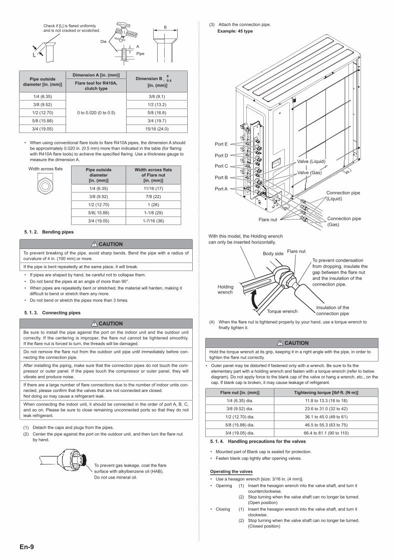
(1) Press the "CHECK" switch for 3 seconds or more.
2WS
CHECK
(2) The number of indoor units (and the places) connected through the communication lines is displayed.• If the displayed number of units (places) and the installed number of units
(places) is the same, proceed to step (3).• If the displayed number of units (places) and the installed number of units
(places) is not the same, shut off the power and check whether the indoor and outdoor communication lines are properly connected.
• If there is no operation for 1 minute, the LED will return to the original display. (POWER/MODE LED: ON)
FEDCMONITORERROR
BA
POWERMODE
Example) When 4 indoor units (A to D) are connected
(2-blink)(3) Press the "CHECK" switch for 3 seconds or more again. Check run is initiated.
• When check run is initiated, all LEDs from A to F will fl ash. (Preliminary operation)
• The LED for each indoor unit will switch off in order as check for each unit is completed.
(2-blink)
FEDCMONITORERROR
BA
POWERMODE
Example) When 4 indoor units (A to D) are connected
(4) After the check run is complete, results will be displayed. Please fi ll the displayed results in the result table accordingly.NOTE:
• Automatic wiring correction will not be completed if the power is turned off while displaying the results. To confi rm the automatic wiring correction, be sure to carry out step (5).• If frost is formed on the outdoor unit while displaying the results, Automatic defrost function will operate. Proceed to step (5) after the defrost function is fi nished.
If the connection is correct [(Example) When 4 indoor units are connected]• After the number of connected units are displayed, the LED for each unit will light
up in order from A to D.
(2-blink)(7 sec.)
(7 sec.)
(7 sec.)
(7 sec.)
FEDCMONITORERROR
BA
POWERMODE
If the connection is incorrect [(Example) When connection of B and C of the 4 units are reversed]• After the number of connected units are displayed, B and C will light up in reverse.
FEDCMONITORERROR
BA
POWERMODE
(7 sec.)
(7 sec.)
(7 sec.)
(7 sec.)
(2-blink)
9380545101-02_IM.indb 159380545101-02_IM.indb 15 2/26/2016 10:16:05 AM2/26/2016 10:16:05 AM

En-16
[How to record the contents]• Please fi ll the displayed results according to the following example.Example 1) When piping A to D is connected but the wires for B and C are connected in reverse.<Displayed results>The LEDs will light up in 7 second intervals in the following order.
FEDCMONITORERROR
BA
POWERMODE
(2-blink)(7 sec.)
(7 sec.)
(7 sec.)
(7 sec.)
<Example of result table>(a) Please write a ● where the LEDs light up in the order that they light up.
A B C D E F
1 ● ● ● ●
2 ●
3 ●
4 ●
5 ●
6
7
(b) Based on the results of step (a), please record as follows.• Please trace the dotted circle with a pen if multiple places light up.
A B C D E F
• Please write the order from A to D in which the LEDs lit up inside the circle.
A B C D E F
A C B D
<Result Table>
A B C D E F
1
2
3
4
5
6
7
A B C D E F
(c) Select the correction method.
Correct the wiring manually.*2Proceed to step (6).
Use the Automatic wiring correc-tion function.*1Proceed to step (5).
Please write down the same results in the label on the reverse side of the service panel.The results recorded are needed at the time of servicing.
NOTES:*1: By using this function, the wiring is automatically corrected according to the pip-
ing.
*2: When correcting the wiring manually, please disconnect the power supply or turn off the breaker during results display, and then change the wiring manually ac-cording to the obtained test results.For example, in Example 1, the wirings connected to the terminals B and C is to be exchanged manually.
(5) During results display, press the "CHECK" switch for 3 seconds or more.• After LEDs A to F have lit in turn, all LEDs will light up indicating that the
automatic wiring correction is completed.
(2-blink)
FEDCMONITORERROR
BA
POWERMODE
(6) Disconnect the power supply or turn off the breaker and wait 10 minutes then turn the power back on and perform test run.NOTE:
• If you do not disconnect the power supply or turn off the breaker, normal operation is not possible.
Others• If an error occurs during check run it will be suspended. Please correct the error and start check run again.• After the check run, if automatic wiring correction is carried out, the indoor unit’s position will be modifi ed to match the piping. (Please note that the display of the optional remote
controller changes.)• If you start check run again after the automatic wiring correction is fi nished, the modifi cation will be reset.
9380545101-02_IM.indb 169380545101-02_IM.indb 16 2/26/2016 10:16:05 AM2/26/2016 10:16:05 AM
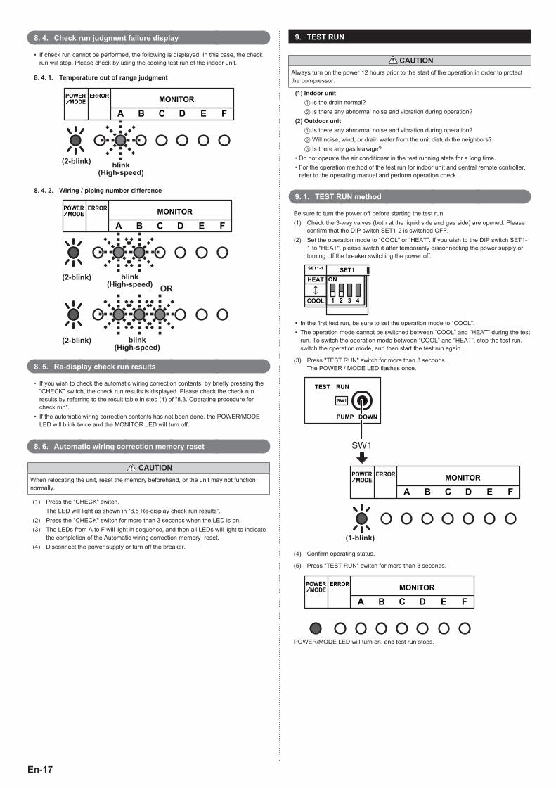
En-17
8. 4. Check run judgment failure display
• If check run cannot be performed, the following is displayed. In this case, the check run will stop. Please check by using the cooling test run of the indoor unit.
8. 4. 1. Temperature out of range judgment
(2-blink) blink(High-speed)
FEDCMONITORERROR
BA
POWERMODE
8. 4. 2. Wiring / piping number difference
FEDCMONITORERROR
BA
POWERMODE
blink(High-speed)
blink(High-speed)
OR(2-blink)
(2-blink)
8. 5. Re-display check run results
• If you wish to check the automatic wiring correction contents, by briefl y pressing the "CHECK" switch, the check run results is displayed. Please check the check run results by referring to the result table in step (4) of "8.3. Operating procedure for check run".
• If the automatic wiring correction contents has not been done, the POWER/MODE LED will blink twice and the MONITOR LED will turn off.
8. 6. Automatic wiring correction memory reset
CAUTIONWhen relocating the unit, reset the memory beforehand, or the unit may not function normally.
(1) Press the "CHECK" switch. The LED will light as shown in “8.5 Re-display check run results”.(2) Press the "CHECK" switch for more than 3 seconds when the LED is on.(3) The LEDs from A to F will light in sequence, and then all LEDs will light to indicate
the completion of the Automatic wiring correction memory reset.(4) Disconnect the power supply or turn off the breaker.
9. TEST RUN
CAUTIONAlways turn on the power 12 hours prior to the start of the operation in order to protect the compressor.
(1) Indoor unit1 Is the drain normal?2 Is there any abnormal noise and vibration during operation?
(2) Outdoor unit1 Is there any abnormal noise and vibration during operation?2 Will noise, wind, or drain water from the unit disturb the neighbors?3 Is there any gas leakage?
• Do not operate the air conditioner in the test running state for a long time.• For the operation method of the test run for indoor unit and central remote controller,
refer to the operating manual and perform operation check.
9. 1. TEST RUN method
Be sure to turn the power off before starting the test run.(1) Check the 3-way valves (both at the liquid side and gas side) are opened. Please
confi rm that the DIP switch SET1-2 is switched OFF.(2) Set the operation mode to “COOL” or “HEAT”. If you wish to the DIP switch SET1-
1 to "HEAT", please switch it after temporarily disconnecting the power supply or turning off the breaker switching the power off.
ON
1 2 3 4
SET1SET1-1
HEAT
COOL
• In the fi rst test run, be sure to set the operation mode to “COOL”.• The operation mode cannot be switched between “COOL” and “HEAT” during the test
run. To switch the operation mode between “COOL” and “HEAT”, stop the test run, switch the operation mode, and then start the test run again.
(3) Press "TEST RUN" switch for more than 3 seconds.The POWER / MODE LED fl ashes once.
PUMP DOWN
1WS
TEST RUN
SW1
FEDCMONITORERROR
BA
POWERMODE
(1-blink)
(4) Confi rm operating status.
(5) Press "TEST RUN" switch for more than 3 seconds.
FEDCMONITORERROR
BA
POWERMODE
POWER/MODE LED will turn on, and test run stops.
9380545101-02_IM.indb 179380545101-02_IM.indb 17 2/26/2016 10:16:05 AM2/26/2016 10:16:05 AM

En-18
10. ERROR CODE
• If an error occurs, the LED will light up to display the error location and the error code.
10. 1. In the event of an error
• The error LED fl ashes quickly.
FEDCMONITORERROR
BA
POWERMODE
blink(High-speed)
10. 2. Error location display
• LEDs A to F of MONITOR light up and display the error location. In the case of an overall error, LEDs A to F of MONITOR do not light up.
Example) Coil error in indoor unit B
FEDCMONITORERROR
BA
POWERMODE
blink(High-speed)
10. 3. Error code display
• While the error is occurring, please briefl y press SW1. The error code is displayed.
FEDCMONITORERROR
BA
POWERMODE
[A(10)] 1Blink(High-speed) (9-blink)
Example) Coil error (Error cord = 9A.1)
F1
2
3
45
6
7
8
9A
C
FJ
PU
EDC
For MONITOR (A and B)
Display mode
LED on:
LED off:
Blink:
(0.5s Light on / 0.5s Light off)
Number of blinking: ( )
A: 10-Blink
C: 11-Blink
F: 12-Blink
J: 13-Blink
P: 14-Blink
U: 15-Blink
Error code Error type
11.3 Serial communication error
11.4 Serial communication error during operation
16.5 Communication error between controller and outdoor unit
22.1 Indoor unit capacity error
5U.1 Indoor unit error
62.1 PCB model information error
62.3 EEPROM access error
62.8 EEPROM data corruption error
63.1 Inverter error
65.3 IPM error (Trip terminal L error)
71.1 Discharge temp. sensor error
72.1 Compressor temp. sensor error
73.2 Heat ex. middle temp. sensor error
73.3 Heat ex. liquid temp. sensor error
74.1 Outdoor temp. sensor error
75.1 Suction gas temp. sensor error
76.1Valve sensor error
76.2
77.1 Heat sink temp. sensor error
84.1 Current sensor 1 error (stoppage permanently)
86.1 Discharge pressure sensor error
94.1 Trip detection
95.1 Compressor motor control error (stoppage permanently)
97.3 Fan motor 1 error (Duty error)
98.3 Fan motor 2 error (Duty error)
99.1 4-way valve error
9A.1 Coil 1 (expansion valve 1) error
A1.1 Discharge temperature 1 error (stoppage permanently)
A3.1 Compressor 1 temperature error
11. PUMP DOWN
WARNINGDuring the pump down operation, make sure that compressor is off before you remove the refrigerant piping. Do not remove the connection pipe while the compressor is in operation with valve open. This may cause abnormal pressure in the refrigeration cycle that leads to breakage and even injury.
PUMP DOWN OPERATIONWhen moving or discarding the air conditioner, in order to consider the environment and avoid the discharge of refrigerant to the atmosphere, please pump down according to the following procedure.
(1) Connect the pressure gauge to the charging port.
(2) Change the DIP switch on the board (SET1-2) to ON*1
*Be sure the power supply is disconnected on the breaker is turned off when changing the DIP switch.
*1: DIP switch (SET1-2)
ON
1 2 3 4
SET1
9380545101-02_IM.indb 189380545101-02_IM.indb 18 2/26/2016 10:16:05 AM2/26/2016 10:16:05 AM
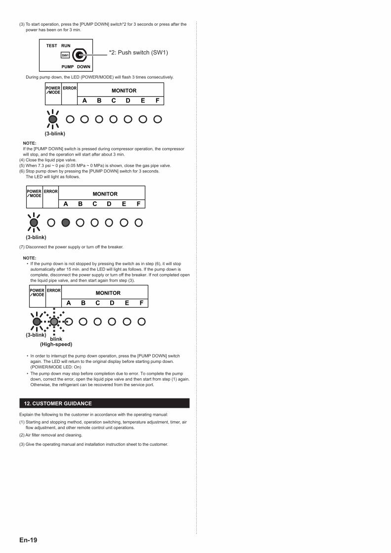
En-19
(3) To start operation, press the [PUMP DOWN] switch*2 for 3 seconds or press after the power has been on for 3 min.
PUMP DOWN
1WS
TEST RUN
*2: Push switch (SW1)
During pump down, the LED (POWER/MODE) will fl ash 3 times consecutively.
(3-blink)
FEDCMONITORERROR
BA
POWERMODE
NOTE:If the [PUMP DOWN] switch is pressed during compressor operation, the compressor will stop, and the operation will start after about 3 min.
(4) Close the liquid pipe valve.(5) When 7.3 psi ~ 0 psi (0.05 MPa ~ 0 MPa) is shown, close the gas pipe valve.(6) Stop pump down by pressing the [PUMP DOWN] switch for 3 seconds.
The LED will light as follows.
FEDCMONITORERROR
BA
POWERMODE
(3-blink)
(7) Disconnect the power supply or turn off the breaker.
NOTE:• If the pump down is not stopped by pressing the switch as in step (6), it will stop
automatically after 15 min. and the LED will light as follows. If the pump down is complete, disconnect the power supply or turn off the breaker. If not completed open the liquid pipe valve, and then start again from step (3).
FEDCMONITORERROR
BA
POWERMODE
(3-blink)blink
(High-speed)
• In order to interrupt the pump down operation, press the [PUMP DOWN] switch again. The LED will return to the original display before starting pump down. (POWER/MODE LED: On)
• The pump down may stop before completion due to error. To complete the pump down, correct the error, open the liquid pipe valve and then start from step (1) again. Otherwise, the refrigerant can be recovered from the service port.
12. CUSTOMER GUIDANCE
Explain the following to the customer in accordance with the operating manual:
(1) Starting and stopping method, operation switching, temperature adjustment, timer, air fl ow adjustment, and other remote control unit operations.
(2) Air fi lter removal and cleaning.
(3) Give the operating manual and installation instruction sheet to the customer.
9380545101-02_IM.indb 199380545101-02_IM.indb 19 2/26/2016 10:16:05 AM2/26/2016 10:16:05 AM