Embed Size (px)
Citation preview
Installation Manual for your NWF EcoBox
Important Note: Not all Transfer Cases use the same length Input Shaft, when test fitting the EcoBox to
the Transfer Case make sure the EcoBox mates to the Transfer case with no gap. The most common
problem people run into is the Input Shaft of their Transfer Case is too long and will bottom out against
the rear Output Bearing before the EcoBox is fully seated. The most common gap to see is 3/4 of an
inch.
If your Input is to long the remedy is to cut the input shaft of the transfer just enough so the EcoBox
mates to the Transfer Case without the input bottoming out on the bearing, or running our 3/4" Spacer.
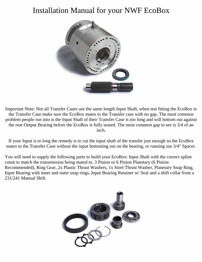
You will need to supply the following parts to build your EcoBox: Input Shaft with the correct spline
count to match the transmission being mated to, 3 Pinion or 6 Pinion Planetary (6 Pinion
Recommended), Ring Gear, 2x Plastic Thrust Washers, 1x Steel Thrust Washer, Planetary Snap Ring,
Input Bearing with inner and outer snap rings, Input Bearing Retainer w/ Seal and a shift collar from a
231/241 Manual Shift.
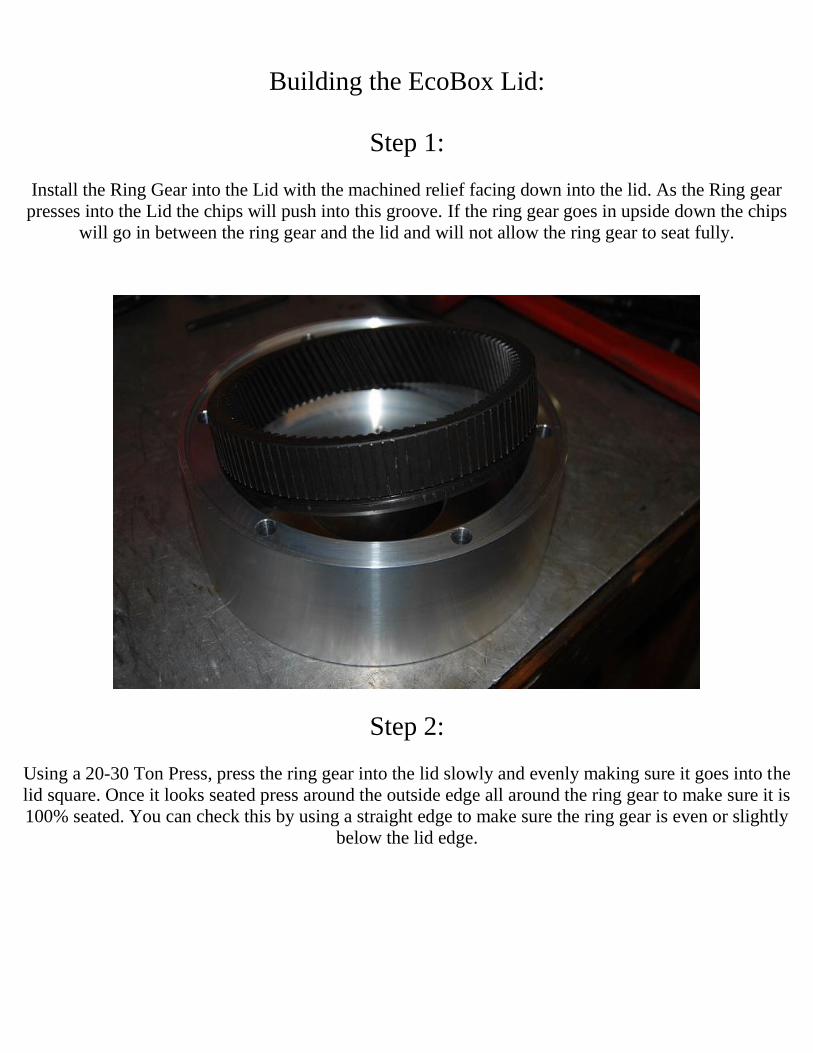
Building the EcoBox Lid:
Step 1:
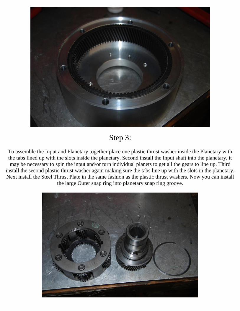
Install the Ring Gear into the Lid with the machined relief facing down into the lid. As the Ring gear
presses into the Lid the chips will push into this groove. If the ring gear goes in upside down the chips
will go in between the ring gear and the lid and will not allow the ring gear to seat fully.
Step 2:
Using a 20-30 Ton Press, press the ring gear into the lid slowly and evenly making sure it goes into the
lid square. Once it looks seated press around the outside edge all around the ring gear to make sure it is
100% seated. You can check this by using a straight edge to make sure the ring gear is even or slightly
below the lid edge.
Step 3:
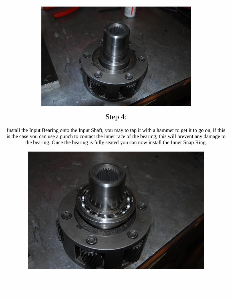
To assemble the Input and Planetary together place one plastic thrust washer inside the Planetary with
the tabs lined up with the slots inside the planetary. Second install the Input shaft into the planetary, it
may be necessary to spin the input and/or turn individual planets to get all the gears to line up. Third
install the second plastic thrust washer again making sure the tabs line up with the slots in the planetary.
Next install the Steel Thrust Plate in the same fashion as the plastic thrust washers. Now you can install
the large Outer snap ring into planetary snap ring groove.
Step 4:
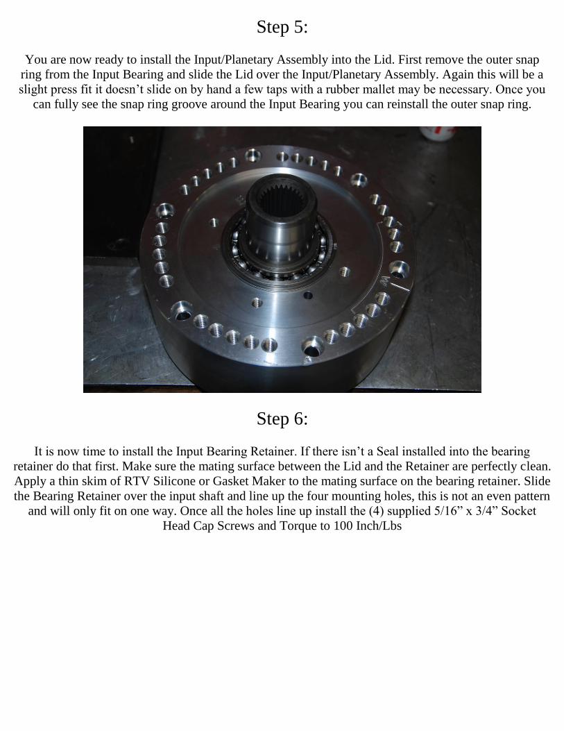
Install the Input Bearing onto the Input Shaft, you may to tap it with a hammer to get it to go on, if this
is the case you can use a punch to contact the inner race of the bearing, this will prevent any damage to
the bearing. Once the bearing is fully seated you can now install the Inner Snap Ring.
Step 5:
You are now ready to install the Input/Planetary Assembly into the Lid. First remove the outer snap
ring from the Input Bearing and slide the Lid over the Input/Planetary Assembly. Again this will be a
slight press fit it doesn’t slide on by hand a few taps with a rubber mallet may be necessary. Once you
can fully see the snap ring groove around the Input Bearing you can reinstall the outer snap ring.
Step 6:
It is now time to install the Input Bearing Retainer. If there isn’t a Seal installed into the bearing
retainer do that first. Make sure the mating surface between the Lid and the Retainer are perfectly clean.
Apply a thin skim of RTV Silicone or Gasket Maker to the mating surface on the bearing retainer. Slide
the Bearing Retainer over the input shaft and line up the four mounting holes, this is not an even pattern
and will only fit on one way. Once all the holes line up install the (4) supplied 5/16” x 3/4” Socket
Head Cap Screws and Torque to 100 Inch/Lbs
Assembling the Base of the EcoBox:
Step 1:
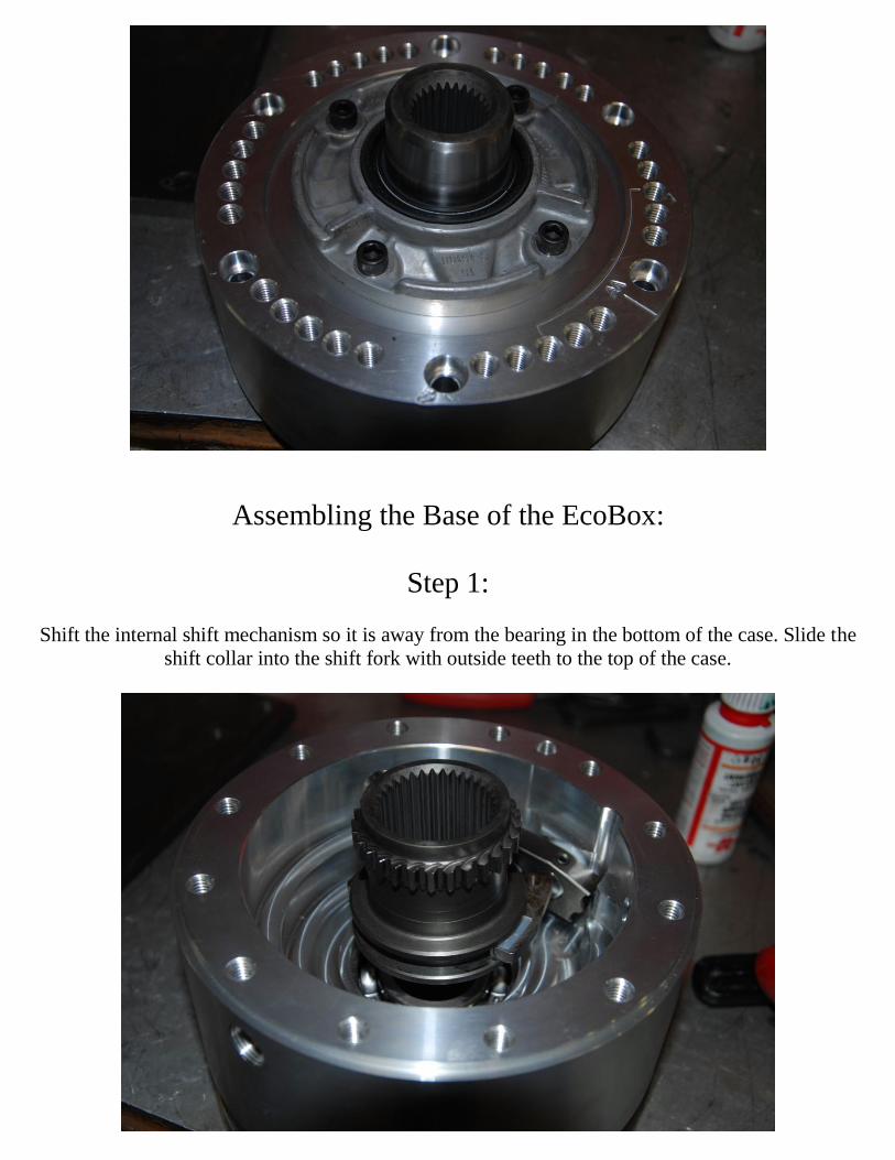
Shift the internal shift mechanism so it is away from the bearing in the bottom of the case. Slide the
shift collar into the shift fork with outside teeth to the top of the case.
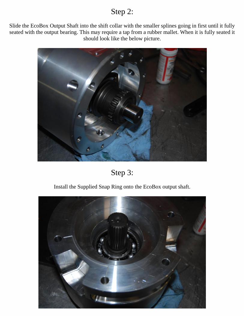
Step 2:
Slide the EcoBox Output Shaft into the shift collar with the smaller splines going in first until it fully
seated with the output bearing. This may require a tap from a rubber mallet. When it is fully seated it
should look like the below picture.
Step 3:
Install the Supplied Snap Ring onto the EcoBox output shaft.
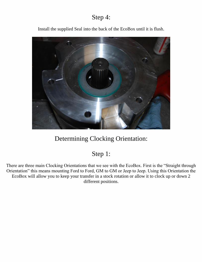
Step 4:
Install the supplied Seal into the back of the EcoBox until it is flush.
Determining Clocking Orientation:
Step 1:
There are three main Clocking Orientations that we see with the EcoBox. First is the “Straight through
Orientation” this means mounting Ford to Ford, GM to GM or Jeep to Jeep. Using this Orientation the
EcoBox will allow you to keep your transfer in a stock rotation or allow it to clock up or down 2
different positions.
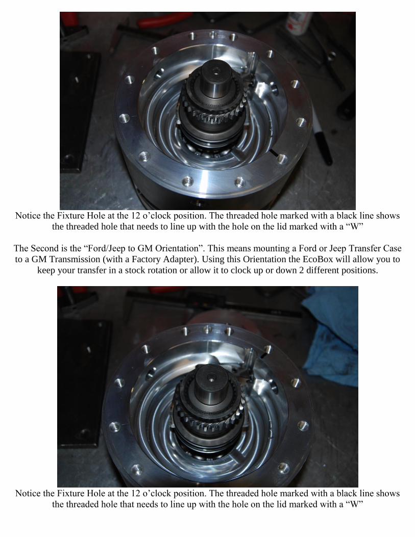
Notice the Fixture Hole at the 12 o’clock position. The threaded hole marked with a black line shows
the threaded hole that needs to line up with the hole on the lid marked with a “W”
The Second is the “Ford/Jeep to GM Orientation”. This means mounting a Ford or Jeep Transfer Case
to a GM Transmission (with a Factory Adapter). Using this Orientation the EcoBox will allow you to
keep your transfer in a stock rotation or allow it to clock up or down 2 different positions.
Notice the Fixture Hole at the 12 o’clock position. The threaded hole marked with a black line shows
the threaded hole that needs to line up with the hole on the lid marked with a “W”
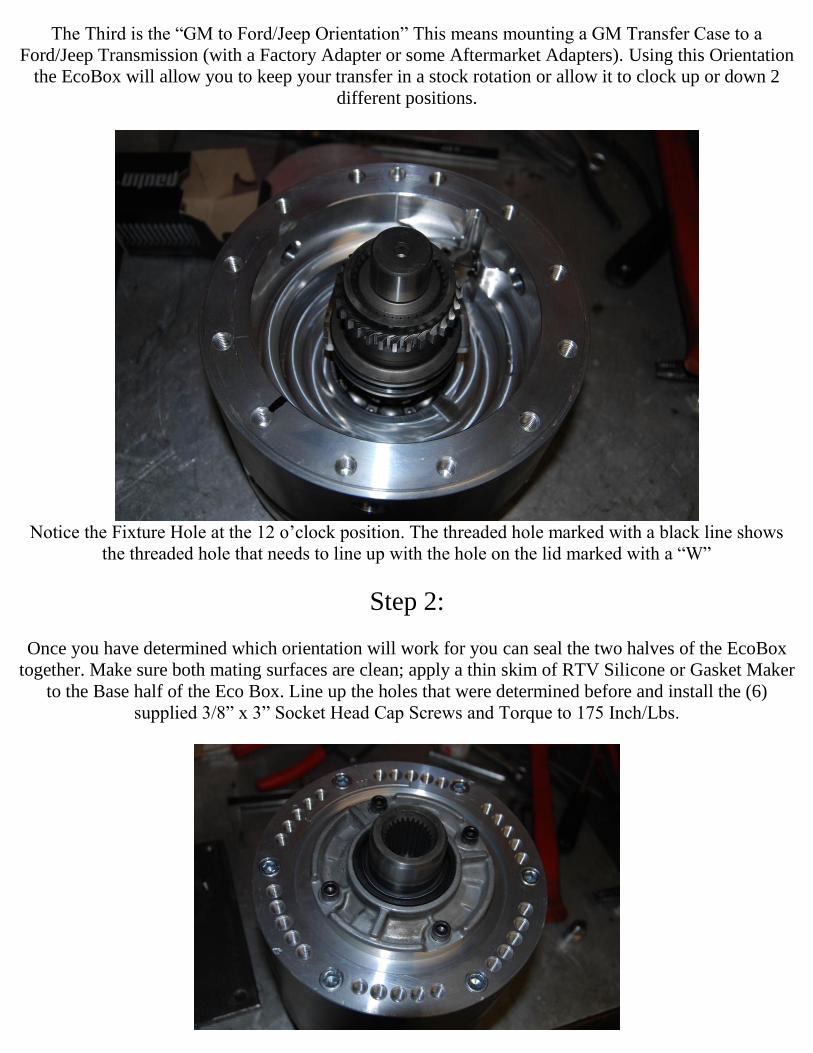
The Third is the “GM to Ford/Jeep Orientation” This means mounting a GM Transfer Case to a
Ford/Jeep Transmission (with a Factory Adapter or some Aftermarket Adapters). Using this Orientation
the EcoBox will allow you to keep your transfer in a stock rotation or allow it to clock up or down 2
different positions.
Notice the Fixture Hole at the 12 o’clock position. The threaded hole marked with a black line shows
the threaded hole that needs to line up with the hole on the lid marked with a “W”
Step 2:
Once you have determined which orientation will work for you can seal the two halves of the EcoBox
together. Make sure both mating surfaces are clean; apply a thin skim of RTV Silicone or Gasket Maker
to the Base half of the Eco Box. Line up the holes that were determined before and install the (6)
supplied 3/8” x 3” Socket Head Cap Screws and Torque to 175 Inch/Lbs.
You will notice the lid has 6 groups of 5 threaded holes. The middle of the 5 threaded holes will clock
your transfer case in a Stock Position.
If you wish to rotate your Drivers Drop Transfer Case Up or Passenger Drop Transfer Case Down
move the Installation Studs Clockwise of the middle threaded holes. The first hole will rotate the
transfer case roughly 1.5” and the second hole will rotate the transfer case roughly 3”.
If you wish to rotate your Drivers Drop Transfer Case Down or Passenger Drop Transfer Case Up
move the Installation Studs Counter Clockwise of the middle threaded holes. The first hole will rotate
the transfer case roughly 1.5” and the second hole will rotate the transfer case roughly 3”.
Once you have the Eco Box Mated to the Transfer case and to the Transmission install the supplied
Brass Breather to the highest Hole on the EcoBox Case, and the brass plugs into the remaining 2 holes.
When routing breather the hose keep the hose away from heat sources as much as possible, never let the
hose dip below the fluid level of the Eco Box and route the Hose as high in the vehicle as possible.
The EcoBox uses 500ml or just over 1/2 Quart of 75/90 Full Synthetic Gear Oil.