Embed Size (px)
Citation preview
Ascent Solar Technologies, Inc. INT19001-05
Installation Manual for WaveSol Light Building- Applied Photovoltaic Modules on Metal and Membrane Roofing Systems
Product List
WaveSol Light BAPV 2-Meter 24 Voc
WSLB-0042-024-ST-06
WSLB-0046-024-ST-06
WaveSol Light BAPV 5 - Meter 96 Voc
WSLB-1400-096-ST-06
WSLB-1200-096-ST-06
Installation Manual for WaveSol Light Building- Applied Photovoltaic Modules on Metal and Membrane Roofing Systems
Ascent Solar Technologies, Inc. Page 2 of 12 INT19001-05
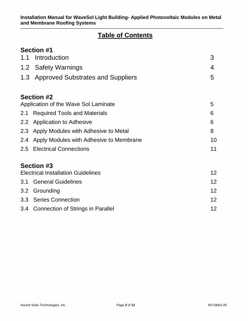
Table of Contents
Section #1 1.1 Introduction 3
1.2 Safety Warnings 4
1.3 Approved Substrates and Suppliers 5
Section #2 Application of the Wave Sol Laminate 5
2.1 Required Tools and Materials 6
2.2 Application to Adhesive 6
2.3 Apply Modules with Adhesive to Metal 8
2.4 Apply Modules with Adhesive to Membrane 10
2.5 Electrical Connections 11
Section #3 Electrical Installation Guidelines 12
3.1 General Guidelines 12
3.2 Grounding 12
3.3 Series Connection 12
3.4 Connection of Strings in Parallel 12
Installation Manual for WaveSol Light Building- Applied Photovoltaic Modules on Metal and Membrane Roofing Systems
Ascent Solar Technologies, Inc. Page 3 of 12 INT19001-05
Section #1
1.1 Introduction
Ascent Solar's WaveSol™ flexible and lightweight thin-film PV technology is an innovative solution for easily integrating solar power into limitless products and applications including building integrated products (BIPV), electronic integrated and electronic portable power products (EIPV), defense, space and more. In addition, the unique flexibility of Ascent Solar's modules enables solar power applications with fabrics and non-flat surfaces. Ascent Solar WaveSol™ solutions provide superior performance benefits by delivering the highest efficiency thin-film on plastic substrates available today. Ascent Solar modules offer excellent power density (power per weight), maximizes overall system performance and reduces overall system costs. This manual describes the procedure for installing Ascent Solar’s WaveSol Light product line of flexible, building-applied photovoltaic (BAPV) modules on approved metal and/or membrane roofing products.
DISCLAIMER OF LIABILITY The information contained in this manual is based on the knowledge and experience of Ascent Solar Technologies, Inc. but such information and suggestions do not constitute a warranty expressed or implied. The methods of installation, use and maintenance of metal and membrane roofing materials are beyond the control of Ascent Solar Technologies, Inc. Ascent Solar Technologies, Inc. assumes no responsibility and expressly disclaims liability for any loss, damage or expense associated with the use, installation or operation of the metal or membrane roofing system. Any liability of Ascent Solar Technologies, Inc. is strictly limited to the Limited Warranty. Ascent Solar Technologies, Inc. reserves the right to make changes to product specifications or to this manual without notice.
Installation Manual for WaveSol Light Building- Applied Photovoltaic Modules on Metal and Membrane Roofing Systems
Ascent Solar Technologies, Inc. Page 4 of 12 INT19001-05
1.2 Safety Warnings
For Installation Personnel Read this manual carefully before installing. This manual does not list all precautions needed for safe work. Follow OSHA or local guidelines. This manual provides guidelines for installation, but it does not guarantee the quality of installation
work. Complete all work in a responsible and professional manner. Electrical work should be performed by a qualified electrician.
Warnings Work under dry conditions with dry tools. Modules exposed to sunlight produce DC electricity. Live parts may cause electric shock. Avoid contact with the metal terminal leads in order to reduce
the risk of electrical shock. Clean module surfaces only with alcohol, window cleaner, or a mild soap & water solution and a
lint-free cloth Use electrically insulated tools when wiring modules. Modules may not be folded or creased during storage and may only be rolled up “cell” side out to a
diameter of no less than 15 inches (0.381m) During installation, roll modules up “cell” side in a diameter of no less than 30 inches (0.762m).
Avoid partially shading modules under load to prevent hot spots and/or reduction in power. Artificially concentrated sunlight shall not be directed onto the module. Do not carry the module by the wires. Do not cut, scratch, or puncture the Module. When trimming the adhesive from around the perimeter of the module, do not cut the module in
any way. Do not stand or walk on the module. Do not immerse unconnected connectors in liquid. Do not drop or allow objects to fall onto the Module. Do not attempt to open, or otherwise dismantle the junction box.
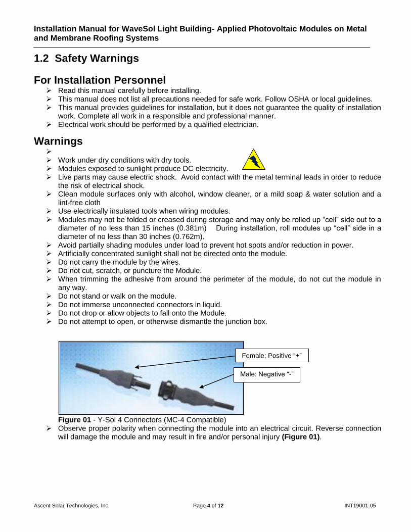
Figure 01 - Y-Sol 4 Connectors (MC-4 Compatible)
Observe proper polarity when connecting the module into an electrical circuit. Reverse connection will damage the module and may result in fire and/or personal injury (Figure 01).
Male: Negative “-”
Female: Positive “+”
Installation Manual for WaveSol Light Building- Applied Photovoltaic Modules on Metal and Membrane Roofing Systems
Ascent Solar Technologies, Inc. Page 5 of 12 INT19001-05
1.3 Approved Substrates
The instructions in this manual are suitable for installing WaveSol Light BAPV modules on specific metal and membrane roofing materials. Applicable metal roofing products are those made of steel with a minimum AZ50 aluminum-zinc coating per ASTM A792/792M (e.g. Galvalume®, Zincalume®, or equivalent) optionally coated with PVDF (e.g. Kynar 500®, Hylar 5000®, Valspar Fluropon®, or equivalent). Applicable membrane roofing products are those made of TPO, EPDM, or modified bitumen. WaveSol Light BAPV modules have been designed to meet performance requirements (per IEC 61646) and safety requirements (per UL 1703, IEC 61730-1 and IEC 61730-2) for building-applied photovoltaic modules when installed following the procedures described in this manual (see Table 1.1 for the status of certification of the various models of WaveSol Light BAPV modules to these standards). While the modules have been evaluated with both metal and membrane roofing, the variability between different types and manufacturers of membrane materials, and the potential influence of underlayments on membrane roof properties, means that adherence to these requirements must be evaluated separately for each type of membrane roofing system.
Table 1.1 Certification Status
Product IEC 61646 UL1703 IEC 61730-1 & IEC 61730-2
WSLB-0042-024-ST-06 Certified For metal roofs pending
WSLB-0046-024-ST-06 Certified For metal roofs pending
WSLB-1400-096-ST-06
WSLB-1200-096-ST-06
Section #2
Application of the Wav Sol Laminate to the Adhesive, and then to Metal or Membrane surfaces
2.1 Required Tools and Materials
Opaque cover (e.g. dark cloth, tarp, cardboard) Lint-free cloths Alcohol, or window cleaner Electrical/insulated gloves Laminate “J” Roller Utility knife 3M UV4000 Fast Cure Silicone Adhesive Sealant cartridges Caulking gun Weighted Roller Straight edge Adco® HelioBond™ PVA 600BT adhesive with paper release liner on one side and plastic release
liner on the other. o http://www.adcocorp.com/product_detail.php?pid=245
Installation Manual for WaveSol Light Building- Applied Photovoltaic Modules on Metal and Membrane Roofing Systems
Ascent Solar Technologies, Inc. Page 6 of 12 INT19001-05
2.2 Application of Adco® HelioBond™ PVA 600BT Adhesive to WaveSol Modules
*Modules should be on a clean, flat surface throughout the adhesive application process.
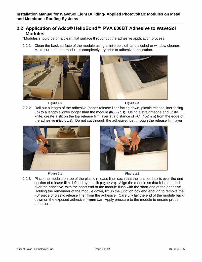
2.2.1 Clean the back surface of the module using a lint-free cloth and alcohol or window cleaner. Make sure that the module is completely dry prior to adhesive application.
Figure 1.1 Figure 1.2
2.2.2 Roll out a length of the adhesive (paper release liner facing down, plastic release liner facing up) to a length slightly longer than the module (Figure 1.1). Using a straightedge and utility knife, create a slit on the top release film layer at a distance of ~6” (152mm) from the edge of the adhesive (Figure 1.2). Do not cut through the adhesive, just through the release film layer.
Figure 2.1 Figure 2.2
2.2.3 Place the module on top of the plastic release liner such that the junction box is over the end section of release film defined by the slit (Figure 2.1). Align the module so that it is centered over the adhesive, with the short end of the module flush with the short end of the adhesive. Holding the remainder of the module down, lift up the junction box end enough to remove the ~6” piece of plastic release liner from the adhesive. Carefully lay the end of the module back down on the exposed adhesive (Figure 2.2). Apply pressure to the module to ensure proper adhesion.
Installation Manual for WaveSol Light Building- Applied Photovoltaic Modules on Metal and Membrane Roofing Systems
Ascent Solar Technologies, Inc. Page 7 of 12 INT19001-05
Figure 3.1 Figure 3.2
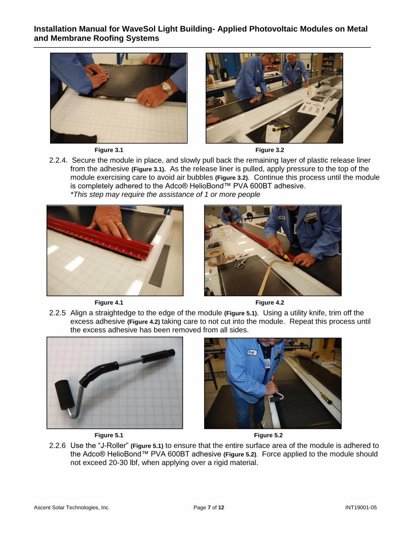
2.2.4. Secure the module in place, and slowly pull back the remaining layer of plastic release liner from the adhesive (Figure 3.1). As the release liner is pulled, apply pressure to the top of the module exercising care to avoid air bubbles (Figure 3.2). Continue this process until the module is completely adhered to the Adco® HelioBond™ PVA 600BT adhesive. *This step may require the assistance of 1 or more people
Figure 4.1 Figure 4.2
2.2.5 Align a straightedge to the edge of the module (Figure 5.1). Using a utility knife, trim off the excess adhesive (Figure 4.2) taking care to not cut into the module. Repeat this process until the excess adhesive has been removed from all sides.
Figure 5.1 Figure 5.2
2.2.6 Use the “J-Roller” (Figure 5.1) to ensure that the entire surface area of the module is adhered to the Adco® HelioBond™ PVA 600BT adhesive (Figure 5.2). Force applied to the module should not exceed 20-30 lbf, when applying over a rigid material.
Installation Manual for WaveSol Light Building- Applied Photovoltaic Modules on Metal and Membrane Roofing Systems
Ascent Solar Technologies, Inc. Page 8 of 12 INT19001-05
2.3 Installation of Wave Sol Modules with Adhesive Backing to Metal Roofing
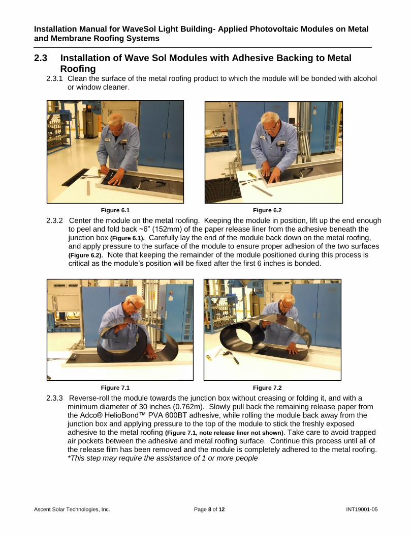
2.3.1 Clean the surface of the metal roofing product to which the module will be bonded with alcohol or window cleaner.
Figure 6.1 Figure 6.2
2.3.2 Center the module on the metal roofing. Keeping the module in position, lift up the end enough to peel and fold back ~6” (152mm) of the paper release liner from the adhesive beneath the junction box (Figure 6.1). Carefully lay the end of the module back down on the metal roofing, and apply pressure to the surface of the module to ensure proper adhesion of the two surfaces (Figure 6.2). Note that keeping the remainder of the module positioned during this process is critical as the module’s position will be fixed after the first 6 inches is bonded.
Figure 7.1 Figure 7.2
2.3.3 Reverse-roll the module towards the junction box without creasing or folding it, and with a minimum diameter of 30 inches (0.762m). Slowly pull back the remaining release paper from the Adco® HelioBond™ PVA 600BT adhesive, while rolling the module back away from the junction box and applying pressure to the top of the module to stick the freshly exposed adhesive to the metal roofing (Figure 7.1, note release liner not shown). Take care to avoid trapped air pockets between the adhesive and metal roofing surface. Continue this process until all of the release film has been removed and the module is completely adhered to the metal roofing. *This step may require the assistance of 1 or more people
Installation Manual for WaveSol Light Building- Applied Photovoltaic Modules on Metal and Membrane Roofing Systems
Ascent Solar Technologies, Inc. Page 9 of 12 INT19001-05
Figure 8.1
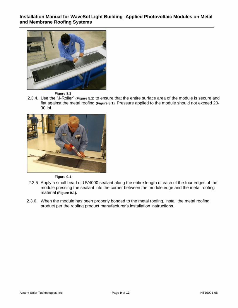
2.3.4. Use the “J-Roller” (Figure 5.1) to ensure that the entire surface area of the module is secure and flat against the metal roofing (Figure 8.1). Pressure applied to the module should not exceed 20-30 lbf.
Figure 9.1
2.3.5 Apply a small bead of UV4000 sealant along the entire length of each of the four edges of the module pressing the sealant into the corner between the module edge and the metal roofing material (Figure 9.1).
2.3.6 When the module has been properly bonded to the metal roofing, install the metal roofing product per the roofing product manufacturer’s installation instructions.
Installation Manual for WaveSol Light Building- Applied Photovoltaic Modules on Metal and Membrane Roofing Systems
Ascent Solar Technologies, Inc. Page 10 of 12 INT19001-05
2.4 Installation of Wave Sol Modules with Adhesive Backing to Membrane
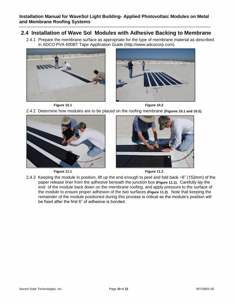
2.4.1 Prepare the membrane surface as appropriate for the type of membrane material as described in ADCO PVA 600BT Tape Application Guide (http://www.adcocorp.com).
Figure 10.1 Figure 10.2
2.4.2 Determine how modules are to be placed on the roofing membrane (Figures 10.1 and 10.2).
Figure 11.1 Figure 11.2
2.4.3 Keeping the module in position, lift up the end enough to peel and fold back ~6” (152mm) of the paper release liner from the adhesive beneath the junction box (Figure 11.1). Carefully lay the end of the module back down on the membrane roofing, and apply pressure to the surface of the module to ensure proper adhesion of the two surfaces (Figure 11.2). Note that keeping the remainder of the module positioned during this process is critical as the module’s position will be fixed after the first 6” of adhesive is bonded.
Installation Manual for WaveSol Light Building- Applied Photovoltaic Modules on Metal and Membrane Roofing Systems
Ascent Solar Technologies, Inc. Page 11 of 12 INT19001-05
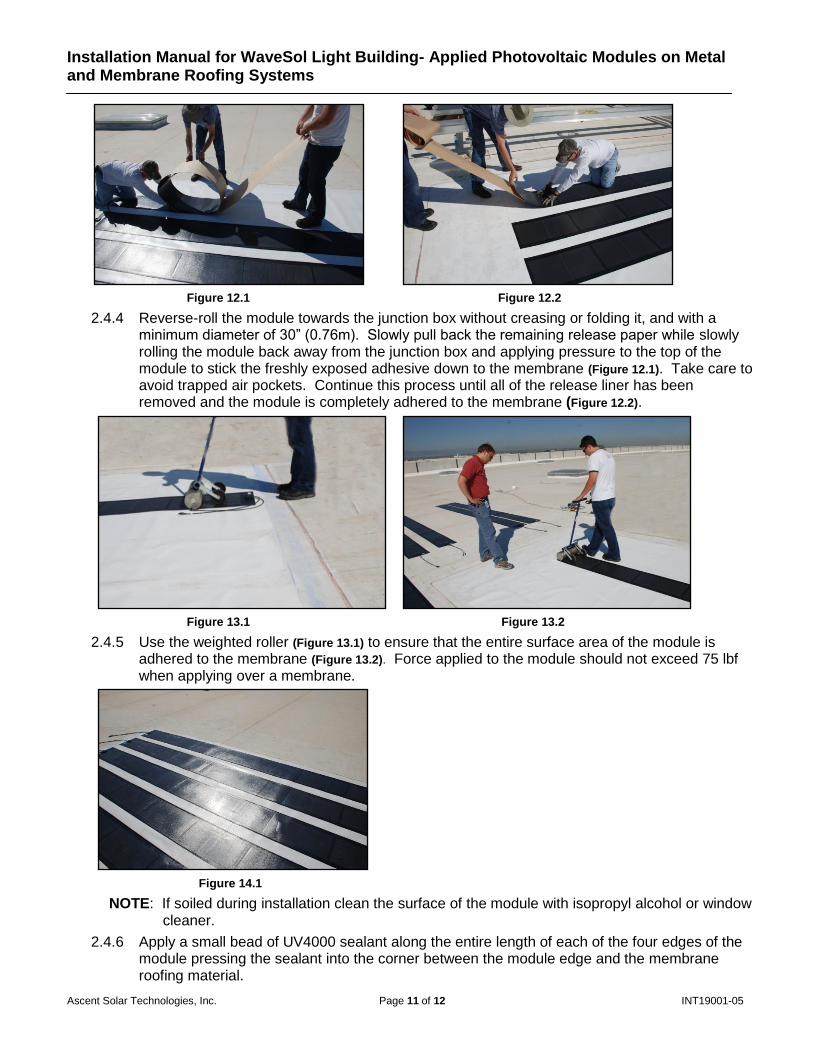
Figure 12.1 Figure 12.2
2.4.4 Reverse-roll the module towards the junction box without creasing or folding it, and with a minimum diameter of 30” (0.76m). Slowly pull back the remaining release paper while slowly rolling the module back away from the junction box and applying pressure to the top of the module to stick the freshly exposed adhesive down to the membrane (Figure 12.1). Take care to avoid trapped air pockets. Continue this process until all of the release liner has been removed and the module is completely adhered to the membrane (Figure 12.2).
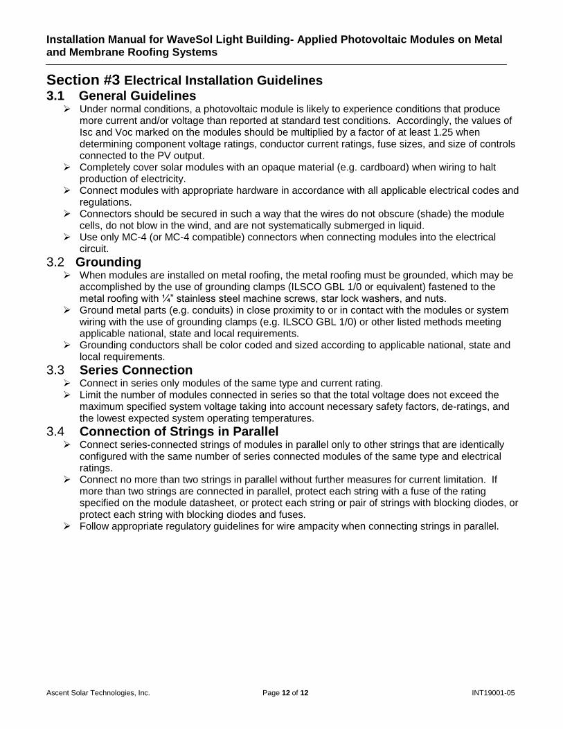
Figure 13.1 Figure 13.2
2.4.5 Use the weighted roller (Figure 13.1) to ensure that the entire surface area of the module is adhered to the membrane (Figure 13.2). Force applied to the module should not exceed 75 lbf when applying over a membrane.
Figure 14.1
NOTE: If soiled during installation clean the surface of the module with isopropyl alcohol or window cleaner.
2.4.6 Apply a small bead of UV4000 sealant along the entire length of each of the four edges of the module pressing the sealant into the corner between the module edge and the membrane roofing material.
Installation Manual for WaveSol Light Building- Applied Photovoltaic Modules on Metal and Membrane Roofing Systems
Ascent Solar Technologies, Inc. Page 12 of 12 INT19001-05
Section #3 Electrical Installation Guidelines
3.1 General Guidelines Under normal conditions, a photovoltaic module is likely to experience conditions that produce
more current and/or voltage than reported at standard test conditions. Accordingly, the values of Isc and Voc marked on the modules should be multiplied by a factor of at least 1.25 when determining component voltage ratings, conductor current ratings, fuse sizes, and size of controls connected to the PV output.
Completely cover solar modules with an opaque material (e.g. cardboard) when wiring to halt production of electricity.
Connect modules with appropriate hardware in accordance with all applicable electrical codes and regulations.
Connectors should be secured in such a way that the wires do not obscure (shade) the module cells, do not blow in the wind, and are not systematically submerged in liquid.
Use only MC-4 (or MC-4 compatible) connectors when connecting modules into the electrical circuit.
3.2 Grounding When modules are installed on metal roofing, the metal roofing must be grounded, which may be
accomplished by the use of grounding clamps (ILSCO GBL 1/0 or equivalent) fastened to the metal roofing with ¼” stainless steel machine screws, star lock washers, and nuts.
Ground metal parts (e.g. conduits) in close proximity to or in contact with the modules or system wiring with the use of grounding clamps (e.g. ILSCO GBL 1/0) or other listed methods meeting applicable national, state and local requirements.
Grounding conductors shall be color coded and sized according to applicable national, state and local requirements.
3.3 Series Connection
Connect in series only modules of the same type and current rating. Limit the number of modules connected in series so that the total voltage does not exceed the
maximum specified system voltage taking into account necessary safety factors, de-ratings, and the lowest expected system operating temperatures.
3.4 Connection of Strings in Parallel Connect series-connected strings of modules in parallel only to other strings that are identically
configured with the same number of series connected modules of the same type and electrical ratings.
Connect no more than two strings in parallel without further measures for current limitation. If more than two strings are connected in parallel, protect each string with a fuse of the rating specified on the module datasheet, or protect each string or pair of strings with blocking diodes, or protect each string with blocking diodes and fuses.
Follow appropriate regulatory guidelines for wire ampacity when connecting strings in parallel.