Embed Size (px)
Citation preview
Installation ManualFor N14 Plus Engines
By TM
2 CBRAKE BY JACOBS™ INSTALLATION MANUAL FOR CUMMINS N14 PLUS ENGINES
Table of Contents Safety Precautions
Section 1: Introduction................................................. 3Tools Required ............................................................. 3Applications ................................................................. 3
Section 2: Engine Preparation .................................... 4
Section 3: Brake Housing Installation .................. 5 - 6Slave Piston Adjustment .............................................. 6
Section 4: Electrical System Installation ................... 7
Section 5: Engine Brake Operation Check ................ 8Bleed Engine Brake Housings ...................................... 8
Section 6: Engine Brake Maintenance ............... 9 - 15Theory of Operation ..................................................... 9Exhaust Blowdown ...................................................... 9Control Valve .............................................................. 10Solenoid Valve............................................................ 12Robo-Lash™ Adjusting Screw ................................... 13Master Piston ............................................................. 13Slave Piston ............................................................... 14
The following symbols in this manual signal potentiallydangerous conditions to the mechanic or equipment.Read this manual carefully. Know when these conditionscan exist. Then, take necessary steps to protect personnelas well as equipment.
THIS SYMBOL WARNS OF POSSIBLEPERSONAL INJURY.
THIS SYMBOL REFERS TO POSSIBLEEQUIPMENT DAMAGE.
NOTE:INDICATES AN OPERATION, PROCEDUREOR INSTRUCTION THAT IS IMPORTANTFOR CORRECT SERVICE.
Fuels, electrical equipment, exhaust gases and movingengine parts present potential hazards that could result inpersonal injury. Take care when installing an engine brake.Always use correct tools and proper procedures asoutlined in this manual.
SEE DRIVER’S MANUAL FOR PROPERENGINE BRAKE DRIVER TECHNIQUES.
THE CBRAKE BY JACOBS™ ENGINERETARDER IS A VEHICLE SLOWINGDEVICE, NOT A VEHICLE STOPPINGDEVICE. IT IS NOT A SUBSTITUTE FORTHE SERVICE BRAKING SYSTEM. THEVEHICLE’S SERVICE BRAKES MUST BEUSED TO BRING THE VEHICLE TO ACOMPLETE STOP.
CBRAKE BY JACOBS™ INSTALLATION MANUAL FOR CUMMINS N14 PLUS ENGINES 3
Section 1: IntroductionTools Required1. 7/16” 12 point socket for housing mounting screws
2. 0.023” feeler gage, Cummins P/N 3871534
3. 3/4” socket for solenoid
4. 7/8” crowfoot wrench for Robo-Lash™ adjustingscrew nut
5. 3/8” hex socket or open-end wrench for Robo-Lash™adjusting screw
6. 7/16” hex socket for master piston capscrew
NOTE:NO ENGINE CONVERSION PARTS AREREQUIRED FOR MODEL 455B AND 455CINSTALLATIONS ON N14 PLUS CUMMINSENGINES.
Application Notes
THE CBRAKE BY JACOBS™ MODEL 455BAND 455C ENGINE BRAKES ARE FOR USEON CUMMINS N14 PLUS ENGINES ONLY.CONSULT YOUR LOCAL CUMMINSDISTRIBUTOR OR DEALER TO VERIFYYOUR ENGINE CPL IS AN N14 PLUSENGINE. MISAPPLICATION COULD RESULTIN ENGINE AND/OR ENGINE BRAKEDAMAGE. REFER TO CUMMINS BULLETINSAND INSTRUCTIONAL LITERATURE FORSPECIFIC APPLICATION INFORMATION.
NOTE:MODEL 455A WAS FORMERLY USED ON1995 AND LATER N14 PLUS 310E - 370EESP I & ESP II ENGINES. MODEL 455A HASBEEN DISCONTINUED AND SUPERCEDEDBY MODEL 455B. MODEL 455A ENGINEBRAKES CAN BE UPGRADED TO MODEL455B BY CHANGING THE ROBO-LASH™TO CUMMINS P/N 3871699 AND MARKINGTHE NAMEPLATE TO INDICATE THECHANGE TO MODEL 455B.
4 CBRAKE BY JACOBS™ INSTALLATION MANUAL FOR CUMMINS N14 PLUS ENGINES
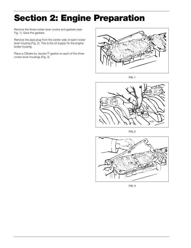
Remove the three rocker lever covers and gaskets (seeFig. 1). Save the gaskets.
Remove the pipe plug from the center web of each rockerlever housing (Fig. 2). This is the oil supply for the enginebrake housing.
Place a CBrake by Jacobs™ gasket on each of the threerocker lever housings (Fig. 3).
Section 2: Engine Preparation
FIG. 1
FIG. 2
FIG. 3
CBRAKE BY JACOBS™ INSTALLATION MANUAL FOR CUMMINS N14 PLUS ENGINES 5
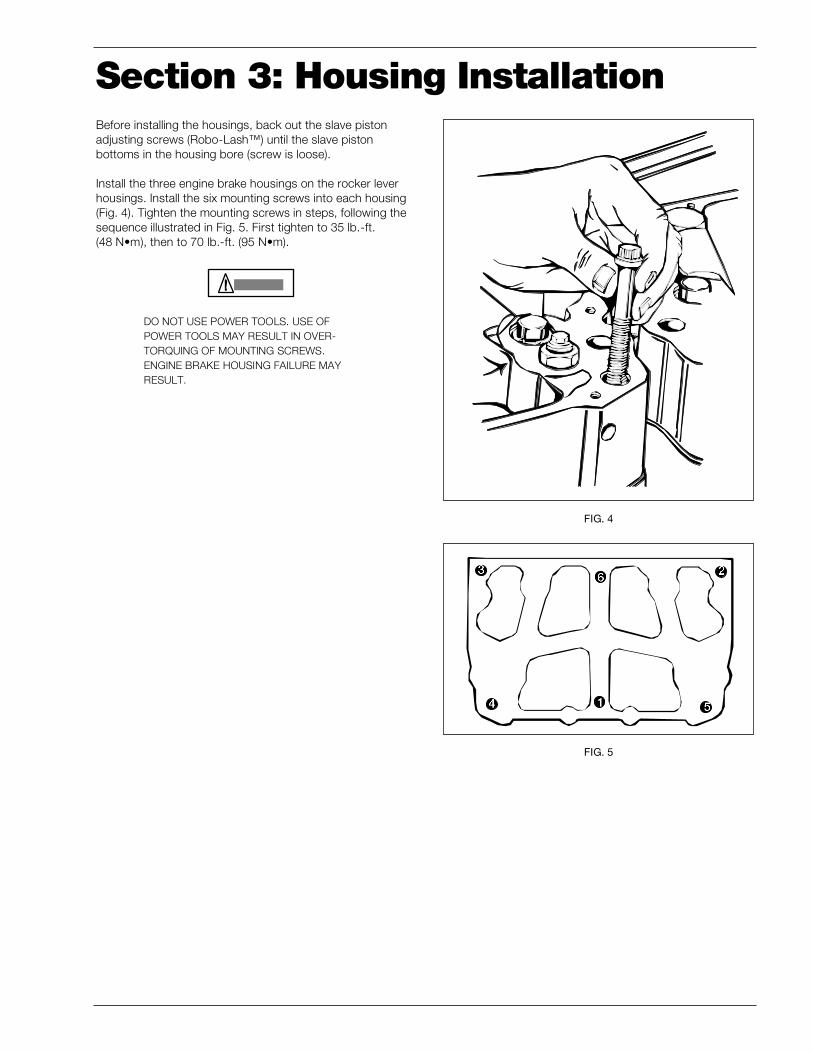
Before installing the housings, back out the slave pistonadjusting screws (Robo-Lash™) until the slave pistonbottoms in the housing bore (screw is loose).
Install the three engine brake housings on the rocker leverhousings. Install the six mounting screws into each housing(Fig. 4). Tighten the mounting screws in steps, following thesequence illustrated in Fig. 5. First tighten to 35 lb.-ft.(48 N•m), then to 70 lb.-ft. (95 N•m).
DO NOT USE POWER TOOLS. USE OFPOWER TOOLS MAY RESULT IN OVER-TORQUING OF MOUNTING SCREWS.ENGINE BRAKE HOUSING FAILURE MAYRESULT.
FIG. 4
Section 3: Housing Installation
FIG. 5
6 CBRAKE BY JACOBS™ INSTALLATION MANUAL FOR CUMMINS N14 PLUS ENGINES
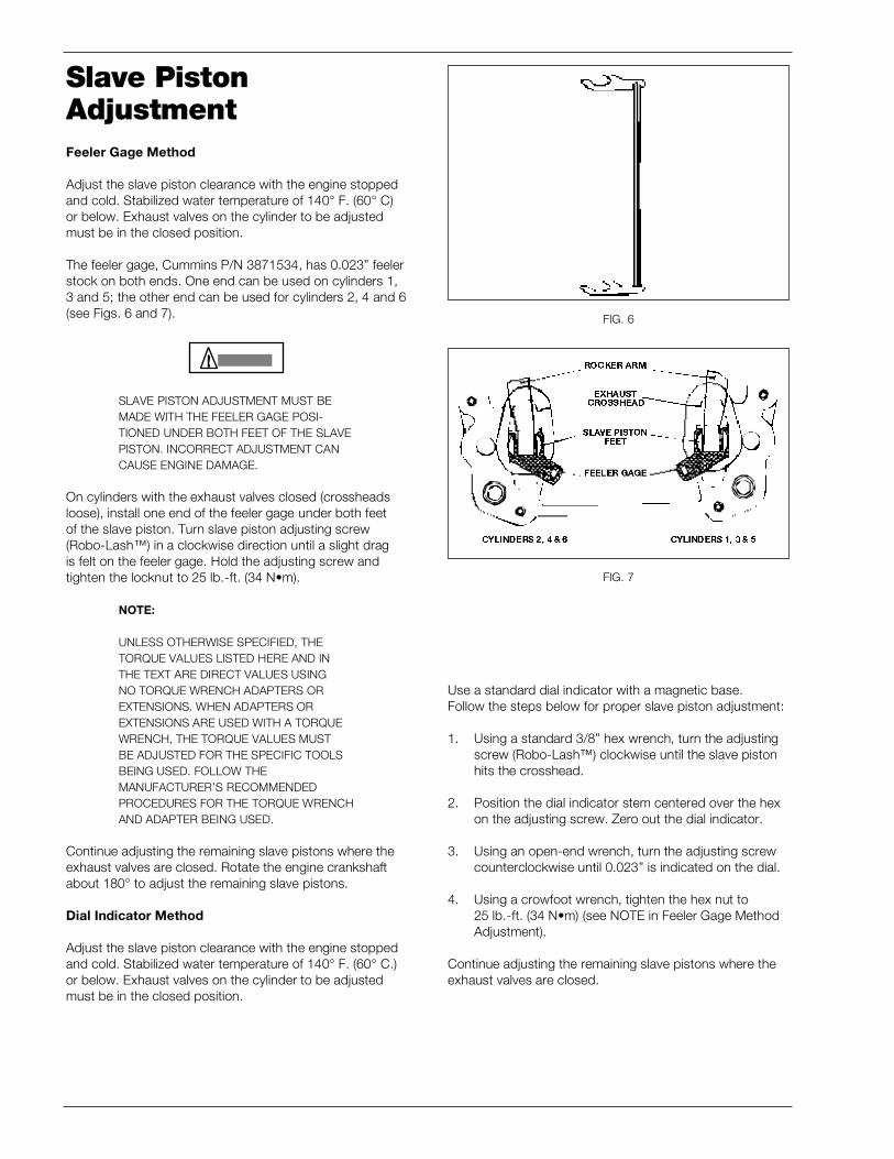
Slave PistonAdjustmentFeeler Gage Method
Adjust the slave piston clearance with the engine stoppedand cold. Stabilized water temperature of 140° F. (60° C)or below. Exhaust valves on the cylinder to be adjustedmust be in the closed position.
The feeler gage, Cummins P/N 3871534, has 0.023” feelerstock on both ends. One end can be used on cylinders 1,3 and 5; the other end can be used for cylinders 2, 4 and 6(see Figs. 6 and 7).
SLAVE PISTON ADJUSTMENT MUST BEMADE WITH THE FEELER GAGE POSI-TIONED UNDER BOTH FEET OF THE SLAVEPISTON. INCORRECT ADJUSTMENT CANCAUSE ENGINE DAMAGE.
On cylinders with the exhaust valves closed (crossheadsloose), install one end of the feeler gage under both feetof the slave piston. Turn slave piston adjusting screw(Robo-Lash™) in a clockwise direction until a slight dragis felt on the feeler gage. Hold the adjusting screw andtighten the locknut to 25 lb.-ft. (34 N•m).
NOTE:
UNLESS OTHERWISE SPECIFIED, THETORQUE VALUES LISTED HERE AND INTHE TEXT ARE DIRECT VALUES USINGNO TORQUE WRENCH ADAPTERS OREXTENSIONS. WHEN ADAPTERS OREXTENSIONS ARE USED WITH A TORQUEWRENCH, THE TORQUE VALUES MUSTBE ADJUSTED FOR THE SPECIFIC TOOLSBEING USED. FOLLOW THEMANUFACTURER’S RECOMMENDEDPROCEDURES FOR THE TORQUE WRENCHAND ADAPTER BEING USED.
Continue adjusting the remaining slave pistons where theexhaust valves are closed. Rotate the engine crankshaftabout 180° to adjust the remaining slave pistons.
Dial Indicator Method
Adjust the slave piston clearance with the engine stoppedand cold. Stabilized water temperature of 140° F. (60° C.)or below. Exhaust valves on the cylinder to be adjustedmust be in the closed position.
FIG. 6
FIG. 7
Use a standard dial indicator with a magnetic base.Follow the steps below for proper slave piston adjustment:
1. Using a standard 3/8” hex wrench, turn the adjustingscrew (Robo-Lash™) clockwise until the slave pistonhits the crosshead.
2. Position the dial indicator stem centered over the hexon the adjusting screw. Zero out the dial indicator.
3. Using an open-end wrench, turn the adjusting screwcounterclockwise until 0.023” is indicated on the dial.
4. Using a crowfoot wrench, tighten the hex nut to25 lb.-ft. (34 N•m) (see NOTE in Feeler Gage MethodAdjustment).
Continue adjusting the remaining slave pistons where theexhaust valves are closed.
CBRAKE BY JACOBS™ INSTALLATION MANUAL FOR CUMMINS N14 PLUS ENGINES 7
Section 4: Electrical Installation
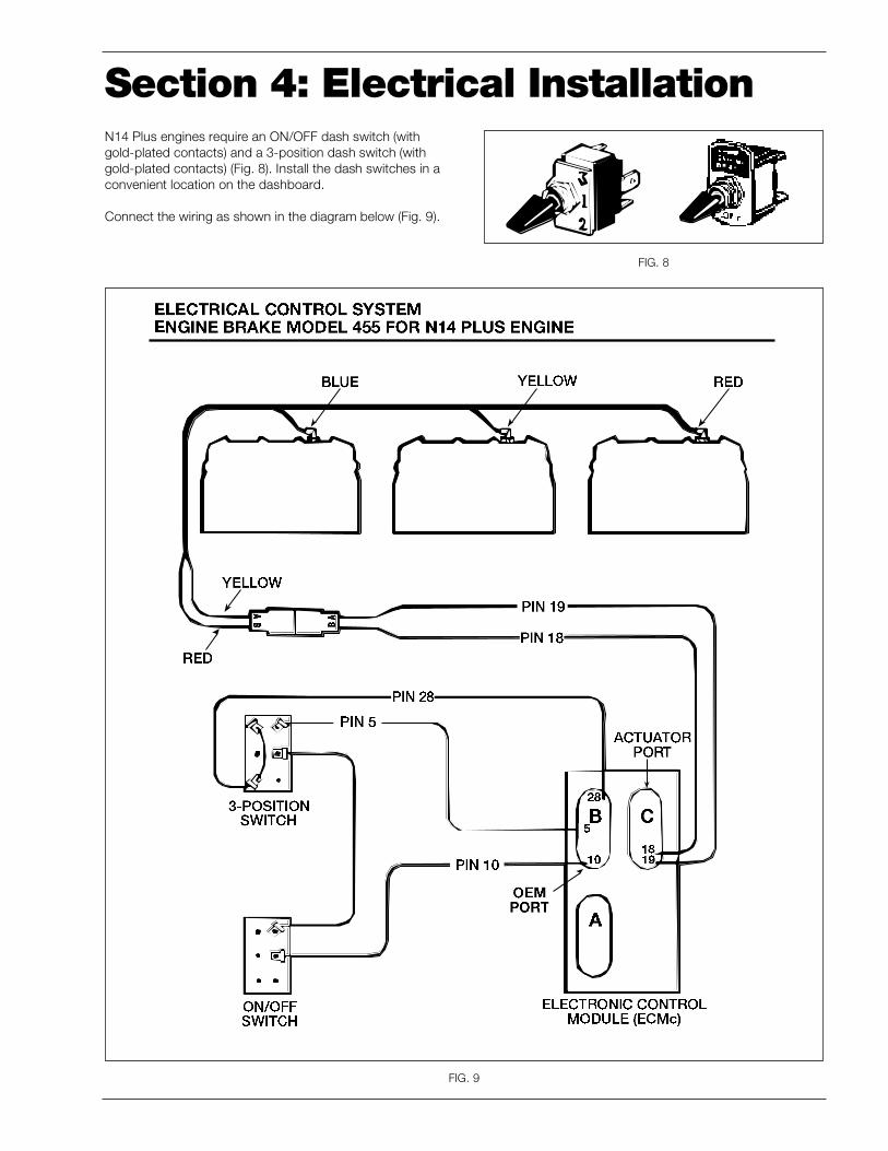
FIG. 8
N14 Plus engines require an ON/OFF dash switch (withgold-plated contacts) and a 3-position dash switch (withgold-plated contacts) (Fig. 8). Install the dash switches in aconvenient location on the dashboard.
Connect the wiring as shown in the diagram below (Fig. 9).
FIG. 9
8 CBRAKE BY JACOBS™ INSTALLATION MANUAL FOR CUMMINS N14 PLUS ENGINES
Section 5: Brake Operation CheckBleed Brake Housings
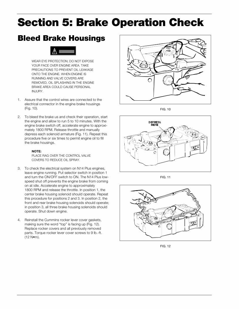
WEAR EYE PROTECTION; DO NOT EXPOSEYOUR FACE OVER ENGINE AREA. TAKEPRECAUTIONS TO PREVENT OIL LEAKAGEONTO THE ENGINE. WHEN ENGINE ISRUNNING AND VALVE COVERS AREREMOVED, OIL SPLASHING IN THE ENGINEBRAKE AREA COULD CAUSE PERSONALINJURY.
1. Assure that the control wires are connected to theelectrical connector in the engine brake housings(Fig. 10).
2. To bleed the brake us and check their operation, startthe engine and allow to run 5 to 10 minutes. With theengine brake switch off, accelerate engine to approxi-mately 1800 RPM. Release throttle and manuallydepress each solenoid armature (Fig. 11). Repeat thisprocedure five or six times to permit engine oil to fillthe brake housings.
NOTE:PLACE RAG OVER THE CONTROL VALVECOVERS TO REDUCE OIL SPRAY.
3. To check the electrical system on N14 Plus engines,leave engine running. Put selector switch in position 1and turn the ON/OFF switch to ON. The N14 Plus low-speed shut off prevents the engine brake from comingon at idle. Accelerate engine to approximately1800 RPM and release the throttle. In position 1, thecenter brake housing solenoid should operate. Repeatthis procedure for positions 2 and 3. In position 2, thefront and rear brake housing solenoids should operate;in position 3, all three brake housing solenoids shouldoperate. Shut down engine.
4. Reinstall the Cummins rocker lever cover gaskets,making sure the word “top” is facing up (Fig. 12).Replace rocker covers and all previously removedparts. Torque rocker lever cover screws to 9 lb.-ft.(12 N•m).
FIG. 10
FIG. 11
FIG. 12
CBRAKE BY JACOBS™ INSTALLATION MANUAL FOR CUMMINS N14 PLUS ENGINES 9
Section 6: Brake MaintenanceTheory of OperationEnergizing the engine brake effectively converts a power-producing diesel engine into a power-absorbing aircompressor. This is accomplished through motion transferusing a master/slave piston arrangement which openscylinder exhaust valves near the top of the normal com-pression stroke, releasing the compressed cylinder chargeto exhaust.
The blowdown of compressed air to atmospheric pressureprevents the return of energy to the engine piston on theexpansion stroke. The effect is a net energy loss, since thework done in compressing the cylinder charge is notreturned during the expansion process.
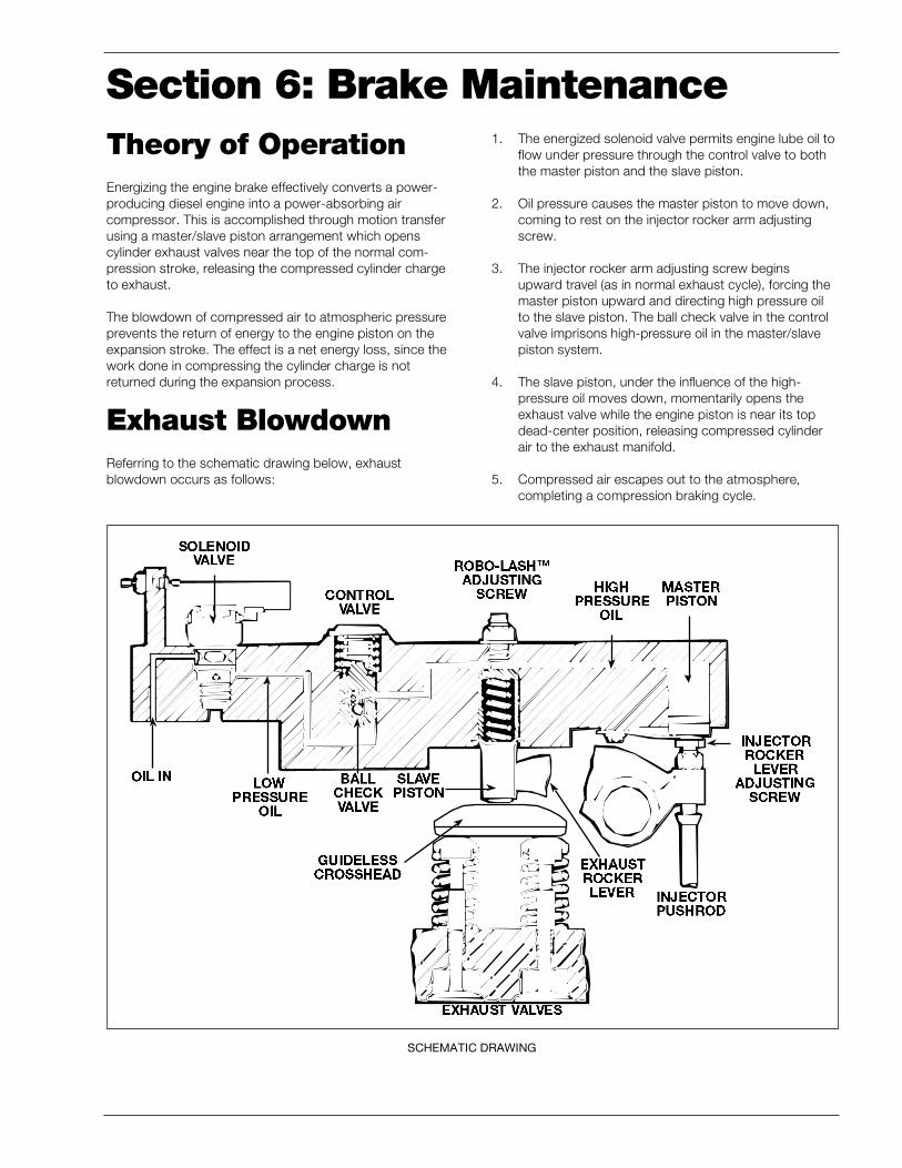
Exhaust BlowdownReferring to the schematic drawing below, exhaustblowdown occurs as follows:
1. The energized solenoid valve permits engine lube oil toflow under pressure through the control valve to boththe master piston and the slave piston.
2. Oil pressure causes the master piston to move down,coming to rest on the injector rocker arm adjustingscrew.
3. The injector rocker arm adjusting screw beginsupward travel (as in normal exhaust cycle), forcing themaster piston upward and directing high pressure oilto the slave piston. The ball check valve in the controlvalve imprisons high-pressure oil in the master/slavepiston system.
4. The slave piston, under the influence of the high-pressure oil moves down, momentarily opens theexhaust valve while the engine piston is near its topdead-center position, releasing compressed cylinderair to the exhaust manifold.
5. Compressed air escapes out to the atmosphere,completing a compression braking cycle.
SCHEMATIC DRAWING
10 CBRAKE BY JACOBS™ INSTALLATION MANUAL FOR CUMMINS N14 PLUS ENGINES
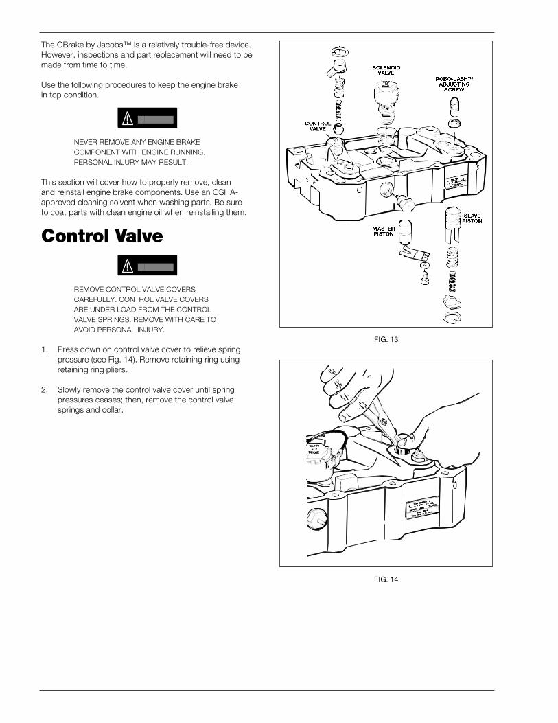
The CBrake by Jacobs™ is a relatively trouble-free device.However, inspections and part replacement will need to bemade from time to time.
Use the following procedures to keep the engine brakein top condition.
NEVER REMOVE ANY ENGINE BRAKECOMPONENT WITH ENGINE RUNNING.PERSONAL INJURY MAY RESULT.
This section will cover how to properly remove, cleanand reinstall engine brake components. Use an OSHA-approved cleaning solvent when washing parts. Be sureto coat parts with clean engine oil when reinstalling them.
Control Valve
REMOVE CONTROL VALVE COVERSCAREFULLY. CONTROL VALVE COVERSARE UNDER LOAD FROM THE CONTROLVALVE SPRINGS. REMOVE WITH CARE TOAVOID PERSONAL INJURY.
1. Press down on control valve cover to relieve springpressure (see Fig. 14). Remove retaining ring usingretaining ring pliers.
2. Slowly remove the control valve cover until springpressures ceases; then, remove the control valvesprings and collar.
FIG. 13
FIG. 14

CBRAKE BY JACOBS™ INSTALLATION MANUAL FOR CUMMINS N14 PLUS ENGINES 11
3. Using needle-nose pliers, remove the control valve(see Fig. 15).
4. Wash the control valves with an approved cleaningsolvent. Push a wire through the hole in the base ofthe valve to the distance required to insure that the ballcheck is free. The ball should lift with light pressure onthe wire. If the ball is stuck, replace the control valve.Dry the valve with compressed air and wipe clean witha paper towel.
5. Thoroughly clean the control valve bore in the housingusing clean paper towels. Dip the control valves inclean lube oil and replace the valve into its bore. Ifbinding occurs, replace the control valve.
6. Reassemble in reverse order the springs, collar (notethe proper direction from Fig. 16), cover and retainingring. Rotate retaining ring at least 90° from slot in thehousing.
FIG. 15
FIG. 16
UP
12 CBRAKE BY JACOBS™ INSTALLATION MANUAL FOR CUMMINS N14 PLUS ENGINES
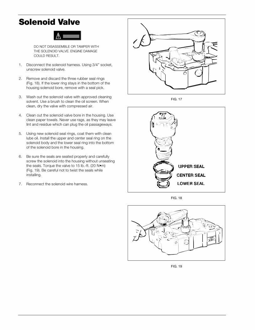
Solenoid Valve
DO NOT DISASSEMBLE OR TAMPER WITHTHE SOLENOID VALVE. ENGINE DAMAGECOULD RESULT.
1. Disconnect the solenoid harness. Using 3/4” socket,unscrew solenoid valve.
2. Remove and discard the three rubber seal rings(Fig. 18). If the lower ring stays in the bottom of thehousing solenoid bore, remove with a seal pick.
3. Wash out the solenoid valve with approved cleaningsolvent. Use a brush to clean the oil screen. Whenclean, dry the valve with compressed air.
4. Clean out the solenoid valve bore in the housing. Useclean paper towels. Never use rags, as they may leavelint and residue which can plug the oil passageways.
5. Using new solenoid seal rings, coat them with cleanlube oil. Install the upper and center seal ring on thesolenoid body and the lower seal ring into the bottomof the solenoid bore in the housing.
6. Be sure the seals are seated properly and carefullyscrew the solenoid into the housing without unseatingthe seals. Torque the valve to 15 lb.-ft. (20 N•m)(Fig. 19). Be careful not to twist the seals whileinstalling.
7. Reconnect the solenoid wire harness.
FIG. 17
FIG. 18
FIG. 19
CBRAKE BY JACOBS™ INSTALLATION MANUAL FOR CUMMINS N14 PLUS ENGINES 13
FIG. 20
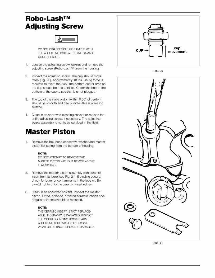
Robo-Lash™Adjusting Screw
DO NOT DISASSEMBLE OR TAMPER WITHTHE ADJUSTING SCREW. ENGINE DAMAGECOULD RESULT.
1. Loosen the adjusting screw locknut and remove theadjusting screw (Robo-Lash™) from the housing.
2. Inspect the adjusting screw. The cup should movefreely (Fig. 20). Approximately 10 lbs. (45 N) force isrequired to move the cup. The bottom center area onthe cup should be free of nicks. Check the hole in thebottom of the cup to see that it is not plugged.
3. The top of the slave piston (within 0.50” of center)should be smooth and free of nicks (this is a sealingsurface.)
4. Clean in an approved cleaning solvent or replace theentire adjusting screw, if necessary. The adjustingscrew assembly is not to be serviced in the field.
Master Piston1. Remove the hex-head capscrew, washer and master
piston flat spring from the bottom of housing.
NOTE:DO NOT ATTEMPT TO REMOVE THEMASTER PISTON WITHOUT REMOVING THEFLAT SPRING.
2. Remove the master piston assembly with ceramicinsert from its bore (see Fig. 21). If binding occurs,check for burrs or contaminants in the lube oil. Becareful not to chip the ceramic insert edges.
3. Clean in an approved solvent. Inspect the masterpiston. Pitted, chipped, cracked ceramic inserts and/or galled pistons should be replaced.
NOTE:THE CERAMIC INSERT IS NOT REPLACE-ABLE. IF CERAMIC IS DAMAGED, INSPECTTHE CORRESPONDING ROCKER ARMADJUSTING SCREWS FOR EXCESSIVEWEAR OR PITTING. REPLACE IF DAMAGED.
FIG. 21
14 CBRAKE BY JACOBS™ INSTALLATION MANUAL FOR CUMMINS N14 PLUS ENGINES
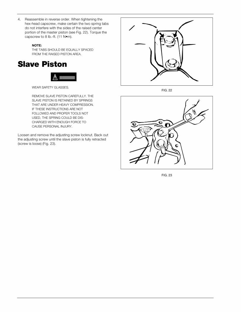
4. Reassemble in reverse order. When tightening thehex-head capscrew, make certain the two spring tabsdo not interfere with the sides of the raised centerportion of the master piston (see Fig. 22). Torque thecapscrew to 8 lb.-ft. (11 N•m).
NOTE:THE TABS SHOULD BE EQUALLY SPACEDFROM THE RAISED PISTON AREA.
Slave Piston
WEAR SAFETY GLASSES.
REMOVE SLAVE PISTON CAREFULLY. THESLAVE PISTON IS RETAINED BY SPRINGSTHAT ARE UNDER HEAVY COMPRESSION.IF THESE INSTRUCTIONS ARE NOTFOLLOWED AND PROPER TOOLS NOTUSED, THE SPRING COULD BE DIS-CHARGED WITH ENOUGH FORCE TOCAUSE PERSONAL INJURY.
Loosen and remove the adjusting screw locknut. Back outthe adjusting screw until the slave piston is fully retracted(screw is loose) (Fig. 23).
FIG. 22
FIG. 23
CBRAKE BY JACOBS™ INSTALLATION MANUAL FOR CUMMINS N14 PLUS ENGINES 15
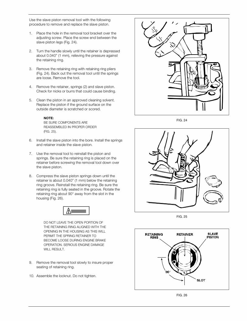
Use the slave piston removal tool with the followingprocedure to remove and replace the slave piston.
1. Place the hole in the removal tool bracket over theadjusting screw. Place the screw end between theslave piston legs (Fig. 24).
2. Turn the handle slowly until the retainer is depressedabout 0.040” (1 mm), relieving the pressure againstthe retaining ring.
3. Remove the retaining ring with retaining ring pliers(Fig. 24). Back out the removal tool until the springsare loose. Remove the tool.
4. Remove the retainer, springs (2) and slave piston.Check for nicks or burrs that could cause binding.
5. Clean the piston in an approved cleaning solvent.Replace the piston if the ground surface on theoutside diameter is scratched or scored.
NOTE:BE SURE COMPONENTS AREREASSEMBLED IN PROPER ORDER(FIG. 25).
6. Install the slave piston into the bore. Install the springsand retainer inside the slave piston.
7. Use the removal tool to reinstall the piston andsprings. Be sure the retaining ring is placed on theretainer before screwing the removal tool down overthe slave piston.
8. Compress the slave piston springs down until theretainer is about 0.040” (1 mm) below the retainingring groove. Reinstall the retaining ring. Be sure theretaining ring is fully seated in the groove. Rotate theretaining ring about 90° away from the slot in thehousing (Fig. 26).
DO NOT LEAVE THE OPEN PORTION OFTHE RETAINING RING ALIGNED WITH THEOPENING IN THE HOUSING AS THIS WILLPERMIT THE SPRING RETAINER TOBECOME LOOSE DURING ENGINE BRAKEOPERATION. SERIOUS ENGINE DAMAGEWILL RESULT.
9. Remove the removal tool slowly to insure properseating of retaining ring.
10. Assemble the locknut. Do not tighten.
FIG. 24
FIG. 25
FIG. 26

Cummins Engine Company, Inc.Box 3005Columbus, IN 47202-3005U.S.A.
CELECT™ is a trademark ofCummins Engine Company, Inc.Bulletin 3698823Printed in U.S.A. 12/97© 1997 Cummins Engine Company, Inc. and Jacobs Vehicle Systems, Inc.
CBrake by Jacobs™ is a trademark ofCummins Engine Company, Inc. andJacobs Vehicle Systems, Inc.
Jacobs P/N 020872B