Embed Size (px)
Citation preview

Yangzhou XinYang Technology Development Co., Ltd
Number: XY-003
Date: 2009.07-Rev003
Installation Manual For Key-Bonding and
Key-Lock Pipe
Yangzhou Xinyang Technology Development Co., Ltd

Yangzhou XinYang Technology Development Co., Ltd
Foreword
This manual introduces the installation procedures of the Key-Bonding and Key-Lock series of
GRE pipe products of Xinyang Company, which varies with the installation of carbon steel
pipelines, stainless steel pipelines, lined pipes and fiberglass pipes with different joining
system. Learning and mastering the instructions in this manual will be helpful for the long-term
stable operation of the installed piping system. All personnel involved in the pipeline
construction must take the training held by the Xinyang Company.
This manual mainly includes the following sections: overview of the product, storage,
transportation and installation preparation of pipeline, bonding of spigot and socket end
between pipe and fittings, locking key joints between pipes, system maintenance and
verification, installation issues to be considered, installation of buried Key-Bonding,Key-
Lock pipeline and Appendix.
This manual introduces in detail the installation procedures and attentions for DN350-DN600
Key-Bonding ,Key-Lock pipeline installation, including both the tapered spigot /socket
joining and locking key joints. The spigot/sockets bonding joint are applied for Key-Bonding
pipe series and fittings installation as well as repair of damaged pipes. As the locking key
connection is different from that of bonding joint or threaded joint, the operators shall check
carefully to ensure the completeness of installation equipments and spare parts and follow the
instructions in this manual strictly.

Yangzhou XinYang Technology Development Co., Ltd
Installation Manual for Key-Bonding and Key-lock Piping System
SectionⅠ Overview .................................................................................................................................. 5
1.1 Pipe Products ............................................................................................................................... 5
1.2 Fitting Products ............................................................................................................................ 5
1.3 Joint System ................................................................................................................................. 5
1.4 Auxiliary devices for field installation of Key-Bonding,Key-Lock Series .................................... 5
1.5 Adhesive .................................................................................................................................... 7
SectionⅡStorage, Transportation and Installation Preparation................................................................ 7
2.1 Storage and transportation of pipe and fittings .......................................................................... 7
2.2 Tools, devices and spare parts required for pipe installation ...................................................... 8
2.3 Adhesive joining at adverse climate ............................................................................................ 9
2.4 Anchor block, guide and support ................................................................................................. 9
2.5 Cutting pipe ............................................................................................................................... 10
2.6 Repairing climate damage ......................................................................................................... 11
SectionⅢ Spigot/Socket end bonding for Key-Bonding series ............................................................... 11
3.1 Precisely connected pipeline ..................................................................................................... 11
3.2 Calculation to achieve desired connection length ................................................................... 11
3.3 Precautions for joint preparation .............................................................................................. 13
3.4 Joint bonding Procedure ............................................................................................................ 13
3.5 Curing of spigot/socket bonding joint........................................................................................ 17
Section Ⅳ Installation for Key-Lock series ............................................................................................ 18
4.1 Installation of joints ................................................................................................................... 18
4.2 Placement of O-ring ................................................................................................................... 19
4.3 Insertion of the pipe .................................................................................................................. 19
4.5 Positioning and alignment of connecting pipes ......................................................................... 20
4.6 Cutting pipe ............................................................................................................................... 21
4.7 Connection with other pipelines or equipment ........................................................................ 21
4.8 Installation of the saddle ........................................................................................................... 21
4.9 Highlights ................................................................................................................................... 22
SectionⅤ Repair of the System .............................................................................................................. 22
5.1 Check the underlying causes of failure joints .................................................................................... 22
5.2 Repairing extensive damaged pipeline ...................................................................................... 22
5.3 Repairing cracking joint and minor pipe damage ...................................................................... 23
5.4 Saddle and reducing tee ............................................................................................................ 24
5.5 Fire/UV Coated pipe .................................................................................................................. 25
5.6 Deluge tee .................................................................................................................................. 25
SectionⅥ Notes for Installation ............................................................................................................. 25
6.1 Recommended test .................................................................................................................... 25
6.2 Startup and running of the system ............................................................................................ 26
6.3 Preventing of water hammer ..................................................................................................... 26
6.4 FRP flange for the Key-Lock piping system ................................................................................ 26
6.5 Connections with other pipeline systems .................................................................................. 27
6.6 Connection with grounding strap or valve................................................................................. 28

Yangzhou XinYang Technology Development Co., Ltd
6.7 Connection with pumps and other equipment ......................................................................... 28
6.8 Pipeline painting ........................................................................................................................ 28
Section Ⅶ Installation of the Buried Key-Bonding, Key-lock Pipelines ............................................. 28
7.1 Construction of trench ............................................................................................................... 28
7.2 Connection over the thench ...................................................................................................... 31
7.3. Place-into trench and backfill ................................................................................................... 32
Safety Warning
Security warning signs shall be set at the installation and construction area to
remind the staff of safety to prevent accidental injuries.
Since the pipeline may contain hazardous media or run under harmful pressure,
the instructions in the manual must be complied with to avoid serious personal
injury and property loss.
The installation personnel should learn by heart the instructions of the installation
tools and adhesives and keep the operation surface clean, stable and
well-ventilated.
When necessary, the installation personnel shall wear appropriate working
clothes.

Yangzhou XinYang Technology Development Co., Ltd
SectionⅠ Overview
1.1 Pipe Products
The performance of GRE pipe products depends on its constituent, such as the variety of resin
and curing agent, the manufacturing process, the thickness of inner corrosion resistance liner
and the outer fire proofing jacket and so on. The pressure rating of Key-Bonding and Key-Lock
piping system designed and manufactured by the Yangzhou Xinyang Technology Development
Co., Ltd are ranged from 1.0MPa-5.0MPa, the temperature rating are 80℃and 120℃ , the pipe
size are ranged from DN350-DN600. In addition to chemical pipelines, both GRE piping
system could also be used, in combination with filament-wound fittings, for salt water pipeline,
fire pipeline and drinking water pipeline.
1.2 Fitting Products
The FRP fitting products matching with the Key-Bonding and Key-Lock pipe products are
manufactured by filament winding process, and connected with the pipe by spigot /socket
bonding joint.
1.3 Joinning System
The spigot/socket bonding joint is used for Key-Bonding series and locking key joint is used
for Key-lock series.
1.4 Auxiliary devices for field installation of Key-Bonding and Key-lock series.
KEY-BONDING JOINT KEY-LOCK JOINT

Yangzhou XinYang Technology Development Co., Ltd
The auxiliary devices in the figure above are respectively: a) winches (x 2), b)
lubricant, c) strip (x 2), d) tension ring (x 4), e) O-Ring, f) bucket, g) screwdriver, h) hammer,
i) locking key. Before installation, the operators shall ensure all these devices are available
with super quality. All the devices may be provided by Xinyang, while the installation
equipment, such as the crane, shall be decided by the contract side.
Electric heating blanket: The electric heat blanket provided by Xinyang
Company is used for heating and curing of bonding joints during
installation. The electric heating strip shall be used together with a voltage
regulator to regulate the curing time of the joint.
Electric blower: The electric blower may be used to heat the bonding
joint, with power not less than 1500 watts.
Field taper shaver
The electric
taper shaver is
used for field taper preparation for
DN350-DN600 pipes during
installation, while the manual taper
shaver is used for field taper
preparation of pipes which OD is
smaller than DN250.
Electric taper shaver Electric/manual taper shaver

Yangzhou XinYang Technology Development Co., Ltd
Belt clamp
The belt clamps are used in combination with winches to connect bonding
joint pipes and fittings.
1.5 Adhesive
Please refer to Table 1.1 and Table 1.2 for the parameters of adhesive.
The special adhesive for installation of Key-Bonding series is consisted of component A and B,
which shall be mixed before use.
Table 1.1 Approximate amount of adhesive
Table 1.2 Pot life of adhesive
The pot life is the period since the A and B gradients are mixed to the time of gelling.
SectionⅡStorage, Transport and Installation Preparation
2.1 Storage and transport of pipes and fittings
The FRP pipes, fittings and adhesive require special storage and transport conditions. During
the storage, handling and transport of Yangzhou Xinyang Key-Bonding ,Key-Lock series pipes
products, special attention shall be paid to prevent impact or other form damages to the pipes
and fittings. To avoid point load of pipes and fittings during transportation, wood boards with
suitable width shall be used to separate pipes of different layers, so as to avoid impact and
bending load of pipes. For pipes larger than DN350, at least 5 pieces of wood partitions shall
be laid between pipe layers. For small sized pipes or loading height larger than 2m, the wood
partitions shall be increased. The wood partitions shall be of a cross section of 100X30 with a
spacing of 2.5m between each other, so as to achieve even load distribution. At both sides of
the pipe piles, wood boards shall be used to fix the pipes and prevent pipe rolling. Attention
shall be taken to avoid sharp or uneven hard surface contacting the pipes and damaging the
pipe wall. When the Key-Bonding or Key-Lock pipes are directly placed on the field ground,
stones shall be removed within the storage area.
The Key-Bonding or Key-Lock pipe ends of Xinyang Company has been packaged with soft
protective material, which shall be removed right before installation, so as to avoid pollutants
Adhesive
(Kit)
Pipe size
DN350 DN400 DN450 DN500 DN600
Number of
joints 3 2 1.5 1 1
Adhesive Pot life /21℃(minutes) Storage period
(years)
EP-305-1 18-25 1

Yangzhou XinYang Technology Development Co., Ltd
or impurities getting into the tapered pipe ends. The FRP fittings are packaged in carton or
wooden box and shall be stored in clean dry area. When the fittings are to be removed from the
packages, attention shall be taken to avoid the grinded spigot/ sockets ends exposed directly in
the sunlight.
The pipe wall structure maybe damaged by friction or impaction during transport , therefore,
the pipe wall must be examined thoroughly before installation to avoid any serious mechanical
damages.
Any damaged Key-Bonding and Key-Lock pipes shall not be used, unless they are examined
and approved by the Yangzhou Xinyang Company. The pipe suffered from impact will show
emission-like cracks at the damaged area, for pipes of this kind, the damaged segment shall be
cut off from 300mm apart from each side of damaged section.
2.2 Tools, devices and spare parts required for pipe installation
To maximize the installation efficiency, tools and devices recommended by the Xinyang
Company shall be applied for installation of Key-Bonding and Key-Lock pipes.
A. Necessary tools for DN350-DN600 pipe installation under normal conditions:
1: Chain vice. To prevent the pipe crushed by the chain, rubber sheet or FRP pipe tiles with the
same diameters shall be applied at the contacting surface.
2: Height adjustable pipe bracket;
3: Pipe cutters (cutting saw with diamond blade);
4:40-120 grit sandpaper;
5: Tape-measure;
6: Markers;
7:3-6 pound hammer and 50X100 batten;
8: Manual /electric taper shaver;
9:12-16 pound sledgehammer and 100X100 batten;
10: Winches ;
11: Belt clamp;
12: Field electric grinding machine;
13: Electric portable drill with 30-60 grit grinding wheel;
14: Belt tension chuck (for saddle installation);
15: Lubricant;
16: Elastic O-Ring;

Yangzhou XinYang Technology Development Co., Ltd
17: Nylon locking key;
18: Screwdriver;
19: Clean water
B: Auxiliary devices for installation at low temperature (below 21℃) :
1: Heat source such as electric blower or infrared light;
2: Adhesive insulation box (with temperature maintained at 21℃-26℃)
3: Electric heating blanket;
2.3 Adhesive installation at adverse climate
The Key-Bonding and Key-Lock pipeline of the Xinyang Company could be installed at all
kinds of climate conditions as long as appropriate preventive measures are taken. While warm
climate is most favorable for pipeline installation, the installation time at low temperature will
be 20% -35% longer than that within factory.
A. Precautions for installation at high temperature
The pot life of adhesives will be greatly shortened at ambient temperature exceeding 32℃, thus
the following recommendations shall be observed:
1: Avoid pipe joints directly exposed in the sunlight;
2: Store the adhesive in cool place;
3: Have the mixed adhesive preserved in sealed ice bath (or portable refrigerator);
B. Precautions for installation at low temperature
Low temperature will lengthen the curing time of adhesive, thus the following precautions shall
be taken during pipe installation at low temperature:
1: Have the adhesives reserved at 27℃-32℃ to accelerate curing of the mixture.
2: When the ambient temperature is lower than 21℃, have the connection surface preheated to
23℃-27℃.
3: When the ambient temperature is below 10℃, have the adhesive joints heated with electric
heat strip and have the joints shielded with insulated iron box, so as to prevent heat diffusion.
C. Installation under high humidity
First of all, wipe the joint of pipe or fittings with a dry cloth or heat it with an electric dryer to
remove the moisture. Then, have the adhesive surfaces thoroughly polished with sandpaper and
remove the dust with a clean cotton cloth and finally have the adhesives evenly applied. Have
the joints cured according to the curing requirement at high or low temperature.
2.4 Anchor block, guide and suport

Yangzhou XinYang Technology Development Co., Ltd
A. Pipe hanger
For overhead installation of Key-Bonding series fire pipes of Xinyang
Company, pipe hangers shall be applied. But too many pipe hangers will
degrade the pipeline stability and will cause vibration when the control
valve is operated or the water pump is started or shut down. To improve the
axial stability of the pipeline, have the pipe hangers used in combination
with the guide groove.
B. Pipeline guides
The pipeline guides are of rigid fixed structure to allow axial movement
of the pipeline. Appropriate spacing of the guides is significant to ensure
the movement of expansion joints and expansion rings and prevent pipe
bending. The U-bolts of the pipe guides shall contact the pipe wall loosely to guarantee free
axial movement of the pipeline. The pipe guides shall be installed at both sides of the joints
between pipe and expansion joint or expansion ring.
C. Pipe supports
The purpose of pipe support is to avoid point load at the contact surface, but
the application of pipe brackets does not mean that the pipe guides could be
reduced. A half of the FRP coupling of the same size produced by the
Xinyang Company is recommended as the pipe bracket. At locations of
valve, water pump or heavy equipment along the pipeline, supports shall be installed.
D. Anchor block
The anchor block provides an independent expansion
space for pipeline. Equipment connected to pipelines,
such as the water pump, tank, are equivalent to anchor
block. But for pipe connections with valves, bends,
blind flange and branch, anchor blocks shall be added.
Pipeline expansion shall also be considered for
independent pipeline design. Only one expansion joint
or expansion ring is allowed between two anchor blocks.
The U-bolts of anchor blocks are not allowed to contact
the FRP pipe wall.
2.5 Cutting pipe
When the Key-Bonding and Key-Lock pipes of Xinyang Company are required to be cut for
fittings connection or repairing of damaged segment, an electric cutting saw with diamond
blade is recommended to use.
1: Measure the length to be cut and calculate the insertion length between pipe and fittings.
Clamp plate
Fitting width (not
firm)
Welded or bolt fixed

Yangzhou XinYang Technology Development Co., Ltd
2: Scribe the cutting line around the pipe and ensure the cutting section is vertical to the pipe
axis.
3: Have the pipe fixed to avoid point compression load on the pipe wall. If chain vice or other
mechanical clamps are used, attention shall be taken to avoid point load. Cut the pipe as
smooth as possible and ensure the parallelism between the end surfaces not larger than 3mm
after cutting.
2.6 Climate damage repair
For bonding connection, if the processed surface of pipes or fittings is exposed directly in the
sunlight for over 4 hours, the following measures shall be taken to avoid to make an impact to
the bonding strength of joints.
Remove the UV degradation layer on the spigot end with 80-120 grit sandpaper slightly, as too
much grinding will change the taper of the spigot and socket ends and form void on the bonded
surface. If UV degradation is serious, have the pipe ends cut of 25mm and re-grinded of taper.
For exposed socket, 40-grit sandpaper is recommended to be used to manually re-grind the
joint until new surface is seen; manual grinding must be slight to avoid changing taper angle of
the socket.
SectionⅢ Installation for Key-Bonding Piping System
3.1 Precisely connected pipeline
The Key-Bonding pipes with spigot/socket bonding joint could be installed with precise length
via special alignment. As the tapered surface of the spigot end is made by grinding process, any
minor changes of the tolerance will affect the insertion depth of spigot. If the connecting length
requirement at the pipe end is not too accurate, the impact of length change may not be
considered. Otherwise, the length compensation could be considered. Have the spigot end
re-grinded with a field grinding machine to realize precise connection length.
3.2 Calculation to achieve desired connection length
1: Check the distance from the center line to the end surface of the fitting (A) from the
Key-Bonding FRP fitting manual of the Xinyang Company. Make a plug gauge with 450mm
long pipe segment and then grind it in accordance whit the operation instructions of the
grinding machine.
Check the dry insertion depth of the tapered segment of pipe , which shall be of the factory
tapered spigot length +/-6mm. Insert the tapered segment of pipe into the socket of fitting to
get the dry insertion depth. Since the insertion depth of each fitting socket is different, the
insertion depth of the sockets at both sides of fitting shall be measured with a standard plug
gage made of a segment of FRP pipe. (Note: if the grinding machine is replaced or the set-up of
the device is altered, a standard plug gage shall be remade).

Yangzhou XinYang Technology Development Co., Ltd
As the adhesive is equivalent to lubricant, the insertion depth of pipe with adhesive shall be
always larger than that at dry status, so an additional length of 5mm shall be added to the
measured length (or basing on the field measurement)
Note: The additional length depends on the fitting of socket at dry status. If the size of the
factory-made socket end is altered, the actual size measured at field installation shall be
applied.
2: The cut length of pipe=(CL to CL)-(A+A)+(IL+IL)+ (M+M), of which:
A = distance between the fitting centerline to the end
surface
IL = dry insertion depth
M = additional length arisen at wet status
For flanges, take flange size A
Use the centerline to centerline distance (CL to CL)
to realize precise pipe connection.
Notes: In case of a fitting of DN350-DN500 connected adjacent to other fitting by bonding
process, it would be very difficult to be tensioned by use of winches, if they are not properly
installed, voids will appear in the adhesion area. Hand lay-up is recommended to wrap the
joint of fitting to ensure the tightness.
Table 3.1 Removal size of 1.0 MPa ~ 2.5MPa fitting
Note: The data in the table is used to measure the CL to CL length
(See products manual)
Table 3.2 Removal size of 2.5 MPa ~ 5.0MPa fitting
(See products manual)

Yangzhou XinYang Technology Development Co., Ltd
3.3 Precautions for joint preparation
Grind the spigot end with the recommended shaver/grinding machine in this manual (set-up
the parameter of the shaver in accordance with the instructions). If the socket of the fitting is
exposed in the ambient environment for more than two hours, the inner surface of the socket
shall be re-polished with 40-100 grit sandpaper and wiped of dust with cloth. If the ambient
temperature is lower than 21℃ or the pipe or fitting is exposed in the low temperature too long,
have the bonding surface preheated with an industrial blower or blowtorch before adhesion.
The preheating temperature that the bare hand could withstand is favorable. The polished and
cleaned bonding surface is not allowed to be heated with a blowtorch. If the bonding surface is
touched with bare hands, have it slightly polished with sandpaper.
3.4 A The joint bonding process
1. Measure the required length
a. Scribe a line on the pipe with a ring template.
b. Fix the pipe with a vice grip and protect the pipe with rubber pad
or similar device from damage.
c Have the contaminated pipe wall cleaned before polishing of the
pipe ends.
2. Pipe cutting
a. Use a hacksaw or a grinding wheel.
b. Ensure that the cut end is within the tolerance range listed in
Table A.
c. These tolerances can be measured by keeping the collet end of
shaver parallel and level with the cutting end of the pipe.
Table 3.3: Maximum squareness tolerance of the cut end
Range of pipe size A
(mm) (inch) (mm)
350-400
400-600
14-16
16-24
3.0
5.0
3. Support and fix of pipe
a. Prevent pipe damage
4. Insert the collet into the pipe
a. Rotate the central tension bolt clockwise to fix the collet inside
the pipe

Yangzhou XinYang Technology Development Co., Ltd
5. Adjust the shaver/grinding machine to meet the pipe size
a. Ensure correct taper angle
b. Caution shall be taken during grinding of the first layer as the pipe wall may be uneven.
6. Grind the taper of the pipe.
a. Keep maximum feed rate at 2mm.
b. Grind repeatedly till required taper is processed.
c. Considering the tolerance, sockets of nominal size is recommended to avoid too long or too
short installation length. If the insertion depth is too small, the spigot end shall be grinded to
match the socket.
7. Have all the bonding surfaces grinded
a. Have all the bonding surfaces grinded within 2 hours before the assembly
b. Use a hand drill and a flap wheel or 60 grit sand cloth.
c. The bonding surface shall be clean and dry before grinding, see
step 10.
d. The newly grinded surface shall not be too smooth.
8. Mark the joint.
a. Check the installation length and mark the pipe and fitting to
align the elbow and flange in a straight line.
b. Measure from the spigot end and scribe a line at the insertion depth adding 50mm. After
installation, pull the joints together with the scribed line 50mm from the socket end.
c. During the final installation, the spigot may slide about 5mm into the socket, thus the joint
length at dry insertion shall be 5mm longer than the actual length.
9. Installation of winches
Install a belt clamp at both ends of the component and keep enough space for winches when
pull the joints together. Two winches shall be used under normal conditions with additions
when necessary.

Yangzhou XinYang Technology Development Co., Ltd
10. Drying of bonding surface
a. If the bonding surface is wet or has a relative humidity greater than 75%, it shall be dried.
b. A blower or heating blanket shall be used.
11. Preheating or cooling of the bonding surface
a. The recommended temperature of bonding surface is 15°C -
40°C.
b. Heating blanket could be used to preheat the bonding surface.
c. If the sunlight is too serious, the bonding surface shall be kept in
the shade to avoid the temperature of the bonding surface
exceeding 40°C.
12. Re-polishing
a.If the polished surface is contaminated or kept longer than 2 hours before installation, the
surface shall be re-polished.
13. Cleaning of the polished surface
a. Clean the dust with a dry cloth or brush.
b. Never touch the polished or cleaned surface.
14. Mixing of EP-305-1 adhesive
If the adhesives storage temperature or the temperature of construction environment is lower
than 21℃, preheating is required before mixing with a temperature not exceeding 38℃. The
operation instructions and notes of the adhesives are included in the package and shall be read
in detail before application.
1: Pour the curing agent completely into the package of the resin material.
2: Have the curing agent mixed sufficiently with the resin material. If the resin material is
sealed in an iron can, have the sealing lid cut to facilitate mixing with a wooden strip.
3: Have the adhesive mixed until the mixture is of uniformed color and could flow
continuously from the wooden strip. Scrap the bottom and walls of the can to ensure the
mixture is even.
15. Applying of a thin layer adhesive
a. Apply the adhesive with a spatula or scraper.
b. All the adhesive surfaces (polished surfaces) must be completely covered with adhesives,
with the adhesive thickness of socket about 0.5 mm and that of spigot about 1mm.
c. Too thick adhesive will result in flow blockage.

Yangzhou XinYang Technology Development Co., Ltd
d.Ensure the cylindrical surface of the spigot has sufficient adhesive to be covered by the
socket.
16. Insert the spigot into the socket.
a. Have the spigot end inserted into the pipe socket to have the joint connected with attention
paid to the scribed mark. If the spigot slips from the socket or rotates after insertion, connection
failure may be resulted.
b. Hang two winches on the belt clamps and pull the spigot and
socket together till the joint is fixed, the socket end shall be
50mm from the scribed line.
c. When necessary, wood partition shall be added between the
winches chain and the pipe wall, so as to place the heating
blanket.
d. The winches could only be removed after the adhesive is
fully cured.
17. Remove excessive adhesive
a. Have the excessive adhesive, including that inside the flange,
removed with a spatula.
18. Electrical heating blanket installation
a. Have the joints wrapped with electric heating plank of
suitable size and ensure that the supply cable could be
transferred through the electric heating blanket .
b. Ensure appropriate voltage.
c. Have the electric heating blanket installed according to the
parameters in the table.
d. Insulation wires shall be used for electric heating blanket.
e. The sound contact of the electric heating blanket and pipe
wall is significant for the curing of the adhesive.

Yangzhou XinYang Technology Development Co., Ltd
f. If the temperature is lower than 10°C or cold wind effect exists, the electric heating blanket
shall be covered with insulation material, which shall be at least 100mm overlapped with the
electric heating blanket and could cover the pipe, with the thermostat excluded.
g. Record the initial curing time, have the open pipe ends sealed during curing to avoid cooling
with wind.
! Warning: Never touch the insulating material during the curing with electric heating blanket,
otherwise, your skin may get burned.
3.5 Curing of spigot/socket joint of fittings
A. Curing at ambient temperature
The curing time means of the hardening period of the adhesive. The curing time of EP-305-1 at
15℃ is 24 hours. If the ambient temperature is too high or too low, the adhesive curing time
will be longer or shorter, thus the curing time could be shortened via heating. The maximum
heating temperature for curing recommended by Xinyang Company is 150℃, because the
cured adhesive joints at this temperature could achieve the best mechanical property and
chemical resistance property.
B. High temperature heating blanket
Note: before having the bonding joints cured with electric heating blanket, the adhesive shall
be gelled. The heating blanket is not allowed to be bent or folded with hand, so as to protect
the elements from being damaged.
1. Heating of pipes and fittings
1) The size of the heating blanket shall match that of the pipe and heating blanket for
large-diameter pipes shall not be used for small pipes.
2) Have the pipe joints wrapped with thermal conductive soft material and then carefully wrap
the heating blanket outside the soft material and finally lock tightly the fixing belt of the
heating blanket.
Warning: Never touch the insulating material during joint curing with electric heating blanket
to prevent skin burns.
2. Heating of flanges:
1) To heat the flange with industrial blower, keep the exit of the blower at least 150mm from
the end surface of the flange.
2) To heat DN350-DN600 flanges, the size of the heat strip shall be slightly smaller than that of
the pipe and the belt of the heating blanket shall be removed.
3) Have the heating blanket rolled carefully into a cylinder and inserted into the inner surface
of the flanged joint, then support inner diameter of the heating blanket with a short pipe section
to make the outer diameter of heating blanket completely contact with the flange socket.

Yangzhou XinYang Technology Development Co., Ltd
3. Heating of the saddle
For the bonding of saddle at low temperature, it is suggested to wrap the saddle outer surface
with the heating blanket and have it shielded with an iron incubator with insulation layer. The
curing time shall not be less than two hours. Before applying external force on the saddle, have
its temperature reduced to ambient temperature.
Table 3.4 The curing time of EP-305-1 adhesive by use of heating blanket
The heating blanket can only be removed when the bonding joint is heated and cured as
specified in the above table otherwise continue pipe installation or pressure test can not be
carried out. The curing time in table above fits for the installation environment of 21℃-38℃, if
the ambient temperature is below 21℃, the curing time shall be extended accordingly (Please
refer to the installation requirements at low temperature). If appropriate heating source is not
available, the curing time of adhesive joints at 21℃ -38℃ shall not be less than 24 hours.
The concentrated adhesives will be cured much faster than that in the joint. Therefore,
before the adhesives in the joints are sufficiently cured, pressure test of the pipeline is not
allowed.
Section Ⅳ Connection between Key-Lock Pipes
4.1 Installation of joints
1. Before installation of the Key-Lock series pipe, have the joint protector
at the spigot/socket end removed. The protector is used to keep the
cleanness of the joining surface and the groove of locking key so
remove it just before installation.
2. Clean the socket or the fittings as well as the seal surface with
a dry cloth and brush.
3 Clean the spigot end (locking key and O-ring) groove.
4 Apply a layer of lubricant to the grooves of O-ring and the locking key
of the spigot.
5. Apply sufficient lubricant to the inner surface of the socket and the
grooves of locking key. Have the positioned pipes rotated appropriately
to keep the hole of locking key of socket at the position of 12 o’ clock..
Pipe size(mm) Curing time(minutes)
350-450
450-600
60
120

Yangzhou XinYang Technology Development Co., Ltd
The lubricant shall be applied when the preparation work for
installation is completed.
6. The lubricated surface shall be kept clean, and the joints and seal
face shall be free with any impurities including sand or dust. The O-ring
and joint surface shall be applied with appropriate lubricant, so as to
avoid accidental cutting or slipping of O-ring during installation.
4.2 Placement of O-ring
1 Have the O-ring cleaned with water or clean cloth.
2 Check to ensure the O-ring is not damaged and is of the right size.
3 Have the entire surface of the O-ring lubricated and slide it into the
first groove of the spigot end (O-ring groove).
4 Position the O-ring into groove smoothly with a screwdriver sliding
under the O-ring around the joints. Special attention shall be taken to
protect the O-ring from damage as a qualified O-ring plays a critical
role for waterproof of the joint.
4.3 Insertion of the pipe
1 Align the spigot end and the socket end of the pipeline aligned in a
straight line as proper alignment is critical for qualified connection.
2 Have the joints fully installed at aligned condition and then adjust
connected pipeline to keep its direction same as the trench.
3 Turn the socket end of pipe or fitting to make the key hole at the
location of 12 o’clock for easy insertion of locking key.
4 Place two belt clamps at both sides of the joint with one at the bell or
behind the coupling, the other 1.5m (4.5 ft) from the spigot end.
Ensure that the tension ring is placed at three and nine o'clock position.
5 Winches are proposed to use.
Connect the Winches to the tension ring of belt clamp at both
ends connected, then pull the pipes together.
6. Have the Winches strained at both sides to make the O-ring slide into

Yangzhou XinYang Technology Development Co., Ltd
the groove smoothly without being squeezed out or slid off.
7 Have the spigot inserted into the socket until the scribed line is level to the bell surface.
Rubber pads may be used below the belt clamp to avoid it sliding off. The belt clamp shall not
be too tight to avoid collapse of pipe wall. Rubber pads or FRP saddles may be placed below
the belt clamp to avoid collapse of the pipe wall. The saddles could be made with surplus pipe
segments (cut into 90° tiles).
The entrance shall be straight and smooth to facilitate installation.
8 Observe carefully to see if the entrance concentricity is uniform along the pipeline. When the
scribe mark is 6mm from the end face of socket, have the locking key prepared and inserted.
4.4 Insertion of locking key
1 Check and ensure the locking key is not damaged and is of the right size.
2 Have the front end of the locking key lubricated before inserting it into the hole.
3 Have the lubricated locking key inserted into the hole and pull the pipes slowly together until
the locking key slides into the groove of key. Check the alignment of the joint along the
pipeline and observe the parallelism of the scribe mark with the end face of bell.
4 Have the locking key pressed into the groove of key with a hammer or mallet until suitable
length is inserted.
Make a mark on the locking key at the circumference length of the pipe, with about
75mm-100mm of the locking key kept at the outside.
5 Have the winches and belt clamp removed after the locking key is installed.
4.5 Positioning and alignment of connected pipes
1 After the locking key is installed and the winches and belt clamp removed, rotate the joint to
make it fit with the support or trench bottom. When the pipe is completely supported at the
final position, have the hanging belt released.
Note: When the buried pipeline is installed at the bottom of trench, the hanging belt shall be
placed at the pipe ends to facilitate straightening during installation of the next joint.
2 To prevent too much movement or bending of pipeline at the bends and branches during
hydrostatic test, the pipelines shall be pulled forward with a winches or other means.

Yangzhou XinYang Technology Development Co., Ltd
4.6 Cutting of pipes
Nipple of special length are often used for installation. To cut the pipe and prefabricate the pipe
end in the factory, an adapter shall be connected to the new spigot by bonding process. If the
double-male nipple prefabricated in the factory is applied, field cutting and bonding of the pipe
could be omitted. The special tools, devices and installation instructions are provided by the
representatives of the Xinyang Company.
4.7 Connection with other pipelines or equipment
The GRE pipe could be connected with other metal or thermoplastic pipe with ANSI-B16
150-pound drilling flange, or other flange drilled according to special orders. The
filament-wound flanges (as the picture below) and RF flange shall be connected with a torque
wrench and bolts. The flanges could be sealed soundly with lined steel structure. If the rubber
gasket with thickness of 3mm and Shore hardness of 60-65 is used, the best effect will be
achieved.
Highlights: to connect the GRE pipe with metal pipes, anchor block shall be installed next to
the joint and at the side of the metal pipe, so as to avoid the expansion or contraction of the
metal pipe transferred to the GRE pipe.
4.8 Installation of the saddle
Preparation before bonding
A Have the bonding surface of saddle completely polished within 2 hours before the assembly.
B Use a hand drill and a flap wheel (700 rpm - 2000rpm), or 60 grit sandcloth.
C Keep the bonding surface dry and clean before polishing.
D The polished surface shall be matt like, too smooth is not allowed.
Installation of the saddle
a Scrape off a thin layer of adhesive (about 0.5 mm) from all the bonding surfaces (including
the saddle and pipelines).
b Have the saddle installed at the right position on the pipeline.
c Have the saddle shoulders clamped with belt clamps.
d Have the saddle wrapped with heating blanket of appropriate size and maintained at proper
curing temperature. The curing time could be checked in the Adhesive Manual.
Yangzhou XinYang Technology Development Co., Ltd
4.9 Highlights
This product manual and the recommendations in this manual are based on test data that are
rational and reliable. This manual shall be limited to personnel specially trained under
conventional industrial production and normal working conditions. The variation of application
environment and operational procedures and extrapolation of data may generate unexpected
consequence. We suggest the user-side engineers to verify the expected application of the
product. Since we have no control of the work environment, we expressly deny any
responsibility for the consequences or any indirect loss suffered by the user due to the
application of the data in this manual.
4.10 Safety
The operators shall always wear protective clothing, gloves and
goggles (Figure 16).
SectionⅤ Repair of the System
The Key-lock FRP pipe system of the Xinyang Company is easy to repair and repair of piping
systems generally refers to cutting off of the damaged pipe section or fittings and replaced with
new material.
Warning: before replacing the damaged pipeline, the operators must know clearly the
chemical properties of the fluid inside the pipe to prevent personal injury, and appropriate
protective measures shall be taken if necessary. The pressure rating and the adhesives used
for the pipeline repair must be consistent with the original pipeline.
5.1 Check the underlying causes of failure of bonded joints
Joint back out - If the bead of the spigot is no longer contact the bell, the spigot will be
backward before the adhesive cured.
Buckled Joint - If the joint buckled or misaligned, there will be a large gap at one side of the
bell.
Improperly cured joint - if the adhesive at the edge of the joint is soft or bendable, the joint is
not completely cured.
Weather damaged joint - if the grinded spigot surface turns yellow, the surface may be
excessively exposed to UV. All damaged or improperly installed joints must be repaired or
replaced in accordance with the following instructions.
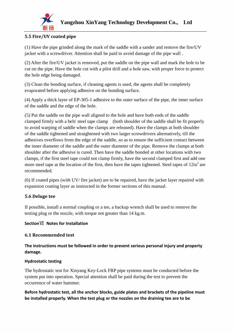
5.2 Repair of severely damaged pipeline
If the diameter of the damaged area of the pipe wall is larger than 2.5cm,
please have the pipe repaired with the following methods.
1: If the pipeline is partially damaged (less than 25mm along the length
and greater than 5 mm around the circumference), check if the pipe
system could be bent or moved, as two FRP coupling and a nipple might be needed for repair.

Yangzhou XinYang Technology Development Co., Ltd
2: Cut off the damaged pipe segment, have the rich resin layer within 125mm of both side of
left pipe end grinded off and prefabricated with a portable grinder or sandpaper of 40 grit or
less (according to pipe size, either taper grinding machine or electric shaver shall be chosen),
then install two hoops and one short pipe segment to repair the damaged area.
Note: This method is for pipelines with sufficient freedom to be raised or moved at
both sides, so as to have the spigot and bell connected.
3: If both side of left pipe end cannot be fully moved and the repair coupling or nipple could
not be installed, the electric/manual shaver shall be used to taper the pipe end and have the pipe
connected with flange.
4: If the pipe end cannot be grinded on the pipe rack, a nipple could be connected by hand
lay-up method.
1) Enough space shall be available at both sides and under the pipe to facilitate the operation.
Cut off the damaged pipe segment and measure the distance between left pipe ends. Cut a new
pipe segment with 3mm spacing between the new segment and both side of left pipe end.
2) Grind off the rich resin layer at both side of left pipe ends. Fix the new pipe segment
between the left pipe ends and maintain straightness with the original pipeline. The pipe
segments must be firmly fixed to avoid movement during pipe wrapping. Paste one 25X50
glass cloth with adhesives at the quarters around the pipeline circumference for positioning.
(See the wrapping method in 4.3)
5.3 Repair of cracked joint and minor pipe damage
Wrapping - if the joint leaks at one location due to improper installation or the diameter of the
damaged area is smaller than 50mm, the damages could be repaired by wrapping of resin and
glass woven roving. The working environment temperature shall be of 24℃ -32℃, and
wrapping in the sunlight is prohibited.
1: Repair with 7-10 oz PPG woven roving or equivalent and the room temperature curing
EP-305-2 repair adhesive.
2: Have the slope between the fitting shoulders to the pipe made level with thicken paste. The
paste layer shall be as thin as possible because of its lower pressure loading capacity.
Note: the pipeline shall be empty with fluid and pressure when the above method is applied
to repair the pipeline.
3: Have the surface re-polished and cleaned after the paste is cured.
4: Have the adhesive and curing agents sufficiently mixed with a wooden spatula till it appears
uniform color and could flow smoothly from the spatula.
5: Apply the mixed adhesive to the polished surface with a clean brush.
6: The glass woven roving shall be cut with gradually increased length, with the short segment
wrapping the inner layer and the longer segment wrapping the outer layers. The woven roving
shall be overlapped at least 50mm during wrapping.

Yangzhou XinYang Technology Development Co., Ltd
7: Lay a piece of woven roving at the middle of the joint and press the cloth till it is completely
saturated with adhesive, then press out the air bubble wrapped in the lamination. During
wrapping the joint, ensure the end edge of each piece of woven roving exceeding the initial
edge, and air bubbles free in the lamination. As the wrapping operation, the wrapped woven
roving will gradually lose their luster, which means that they are wet out by resin.
8: To avoid uneven thickness of the wrapped layer, the second piece of woven roving shall be
wrapped starting from the end of the first piece.
9: To reduce the curing heat release of the wrapped layer, never have the woven roving
wrapped continuously, have the first wrapped layers cured and cooled with a fan at first. Have
the wrapped surface polished and cleaned with a grinding machine or sandpaper before
wrapping of other layers.
10: Attention shall be paid to the bottom of the joint to avoid sagging.
11: When the ambient temperature exceeds 32℃, wrapping in the sunlight is prohibited.
Table 9. Amount of wrapping resin for repair
Pipe size
(mm)
Wrapping layers Glass cloth width
(mm)
Resin amount
(kits)
350
400
450
500
600
14
16
18
20
22
200
200
300
300
350
6.5
8.0
9.5
11.0
13.0
5.4 Saddle and reducing tee
1: saddle – have the saddle placed on the pipe and marked around it.
(1) Have the resin layer of the bonding surface of pipe grinded off with a file, or a portable
grinder or sandpaper (40 grit) (grinding with flexible grinding wheel is more favorable for
large diameter pipes). The surface could be grinded either along the circumference or with
random sequence.
Yangzhou XinYang Technology Development Co., Ltd
5.5 Fire/UV coated pipe
(1) Have the pipe grinded along the mark of the saddle with a sander and remove the fire/UV
jacket with a screwdriver. Attention shall be paid to avoid damage of the pipe wall .
(2) After the fire/UV jacket is removed, put the saddle on the pipe wall and mark the hole to be
cut on the pipe. Have the hole cut with a pilot drill and a hole saw, with proper force to protect
the hole edge being damaged.
(3) Clean the bonding surface, if cleaning agents is used, the agents shall be completely
evaporated before applying adhesive on the bonding surface.
(4) Apply a thick layer of EP-305-1 adhesive to the outer surface of the pipe, the inner surface
of the saddle and the edge of the hole.
(5) Put the saddle on the pipe wall aligned to the hole and have both ends of the saddle
clamped firmly with a belt/ steel tape clamp (both shoulder of the saddle shall be fit properly
to avoid warping of saddle when the clamps are released). Have the clamps at both shoulder
of the saddle tightened and straightened with two larger screwdrivers alternatively, till the
adhesives overflows from the edge of the saddle, so as to ensure the sufficient contact between
the inner diameter of the saddle and the outer diameter of the pipe. Remove the clamps at both
shoulder after the adhesive is cured. Then have the saddle bonded at other locations with two
clamps, if the first steel tape could not clamp firmly, have the second clamped first and add one
more steel tape at the location of the first, then have the tapes tightened. Steel tapes of 12in2
are
recommended.
(6) If coated pipes (with UV/ fire jacket) are to be repaired, have the jacket layer repaired with
expansion coating layer as instructed in the former sections of this manual.
5.6 Deluge tee
If possible, install a normal coupling or a tee, a backup wrench shall be used to remove the
testing plug or the nozzle, with torque not greater than 14 kg.m.
SectionⅥ Notes for Installation
6.1 Recommended test
The instructions must be followed in order to prevent serious personal injury and property
damage.
Hydrostatic testing
The hydrostatic test for Xinyang Key-Lock FRP pipe systems must be conducted before the
system put into operation. Special attention shall be paid during the test to prevent the
occurrence of water hammer.
Before hydrostatic test, all the anchor blocks, guide plates and brackets of the pipeline must
be installed properly. When the test plug or the nozzles on the draining tee are to be
Yangzhou XinYang Technology Development Co., Ltd
installed, stainless steel nuts shall be equipped as required with a torque of not more than
14 kg. M. The following rules must be observed during the hydrostatic test.
The water for hydro test is usually introduced into the pipeline by a DN25 pipe(or a larger size
of pipe according to the size of pipeline)to eliminate air in piping system completely. The water
inlet shall be at the lowest point of the pipeline with the exhaust valve or flange at the highest
point. Close the valve slowly to raise the system pressure gradually. The test pressure shall not
exceed 1.25 times of the lowest pressure rating of the fittings among the piping system. After
the test, open the drain valve and get the water drained when the system pressure drops to
atmospheric pressure again, so as to avoid vacuum collapse due to rapid water drainage of the
piping system.
Notes: 1 Make sure the air within the system is thoroughly exhausted before the test. 2:
Warning: pressure test with air or other gas is not recommended. 3: it is strongly
recommended to conduct pressure test after installation of each segment of pipeline. 4:
Safety precautions: appropriate protective measures shall be taken for any system pressure
test, so as to avoid risks of personal injury and property loss.
6.2 Startup and running of the system
For any pressure piping system, the initial startup must be carried out gradually to prevent
damage to the pipeline or performance degradation due to overload or pressure fluctuations.
One approach is to reduce the start speed of the pump and the opening speed of the exhaust
valve, and an alternative is to start the centrifugal water pump against to a closed adjusting
valve and then open the valve slowly.
6.3 Preventing of water hammer
Water hammer is a term used to describe the serious movement of pipeline when the pressure
fluctuates, which is often caused by sudden shutoff of the valve, power off or other abnormal
running factors. The pressure fluctuations will cause pipeline damages of different forms.
For FRP pipes installed above ground, water hammer usually occurs at the fittings due to the
restraint of excessive pipeline movement because of the anchor block, guide plate and pipe
supports. To solve this issue, installation of a retarder valve, a bypass pipe or a pressure
fluctuation suppressor is proposed.
Gas in the pipeline system can also cause water hammer, so the air in the pipe system must be
completely exhausted when the pipeline runs with full load. Sudden movement of the pipeline
system will cause tremendous noise and instable running of the pipe system will result in water
hammer.
6.4 FRP flange for the Key-Lock piping system
The Xinyang FRP flange complies with the 150 pounds 1"-24" steel flange requirements in the
ANSI B16 standard, in the aspects of diameter, bolt hole number, bolt hole size and distribution.
The size of the bolts shall be determined according to the requirement. The flat gasket shall be
3mm thick with the Shore hardness of 60-70.
Yangzhou XinYang Technology Development Co., Ltd
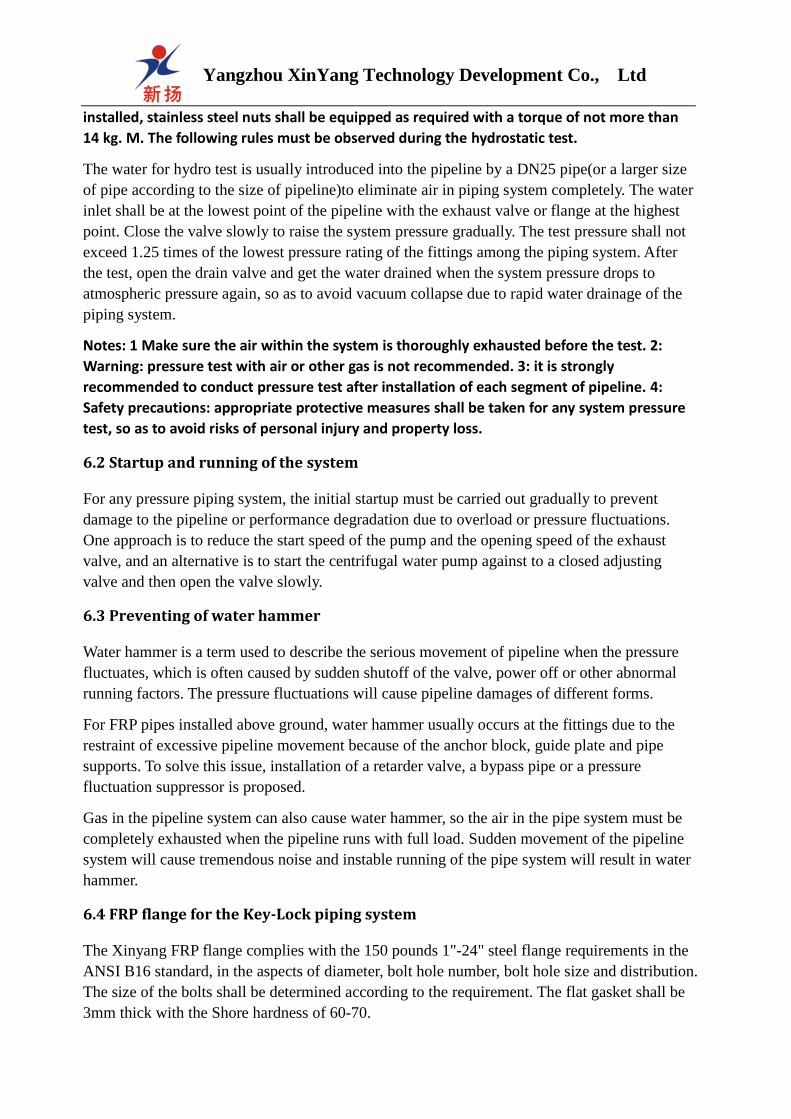
Recommended bolt tightening sequence
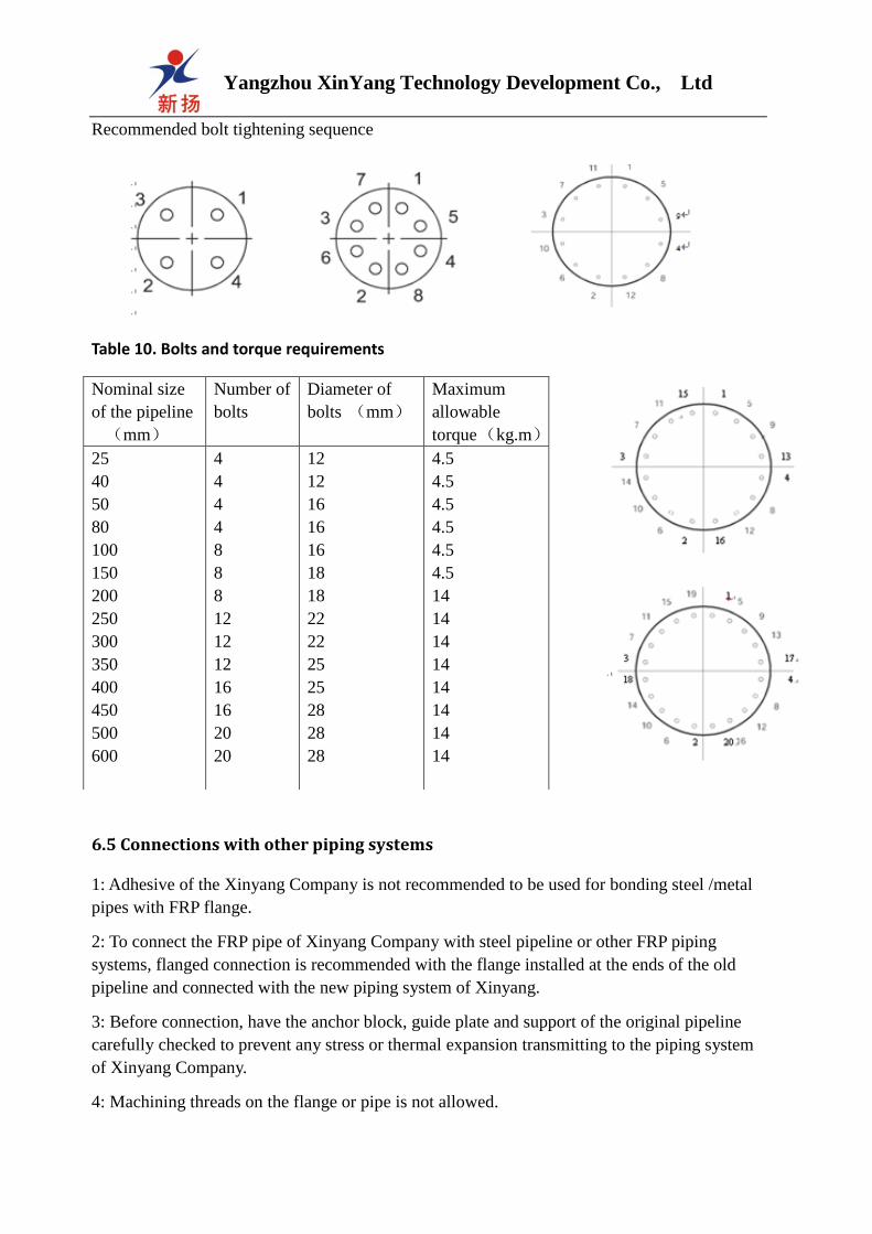
Table 10. Bolts and torque requirements
6.5 Connections with other piping systems
1: Adhesive of the Xinyang Company is not recommended to be used for bonding steel /metal
pipes with FRP flange.
2: To connect the FRP pipe of Xinyang Company with steel pipeline or other FRP piping
systems, flanged connection is recommended with the flange installed at the ends of the old
pipeline and connected with the new piping system of Xinyang.
3: Before connection, have the anchor block, guide plate and support of the original pipeline
carefully checked to prevent any stress or thermal expansion transmitting to the piping system
of Xinyang Company.
4: Machining threads on the flange or pipe is not allowed.
Nominal size
of the pipeline
(mm)
Number of
bolts
Diameter of
bolts (mm)
Maximum
allowable
torque (kg.m)
25
40
50
80
100
150
200
250
300
350
400
450
500
600
4
4
4
4
8
8
8
12
12
12
16
16
20
20
12
12
16
16
16
18
18
22
22
25
25
28
28
28
4.5
4.5
4.5
4.5
4.5
4.5
14
14
14
14
14
14
14
14

Yangzhou XinYang Technology Development Co., Ltd
6.6 Connecting to lug and wafer valve
The sealing type of flat face are commonly used for lined valves of piping system. The
parameters of sealing face of unlined valves could be found in the same valve manual.
Sometimes, the groove at the valve sealing surface edge is too close to the pipeline inner
diameter and does not match the sealing surface of the Xinyang FRP flange. When the Xinyang
FRP pipeline is to be connected with non-flat face flange, the following recommended methods
shall be followed.
1: For unlined, non-integrated sealed lug and wafer valve, gaskets 8.5mm thick and with Shore
hardness of 60-70 shall be applied.
2: For integrated sealed or unlined lug and wafer valve, 0.6mm thick steel spacer with ID equal
to Schedule 40 steel or conforming to the valve
manufacturer’s requirement, shall be used. Gaskets shall be
installed between the steel spacer and FRP flange.
6.7 Connecting to pumps and other equipment
When the Xinyang FRP fire (Key-Bonding series) piping
system are to be connected with pumps or moving
equipment with vibration or shock load, flexible
connections shall be applied with the flexible connectors for
absorbing the shock and eliminating pipe and fitting
deformation generated via stress. Rubber bellows type expansion joints are recommended to
use.
6.8 Pipeline painting
Before painting, the pipe wall shall be clean and dry. The painted surface shall be completely
polished by use of sandpaper or abrasive blasting (the fire or UV jacket is not allowed to be
damaged). The Xinyang FRP pipe wall could be painted with all kinds of high quality epoxy
paint, polyester paint, polyurethane paint, alkyd, or A, B components epoxy paint.
Section Ⅶ Installation of the Key-Bonding and Key-lock Buried Pipelines
7.1 Construction of trench
1. Trench size
Appropriate trench size shall be determined to provide a proper space for the pipeline
installation, with the depth calculated in accordance with the bedding thickness of trench, the
pipe height and backfill thickness. The trench shall be wide enough to accommodate the
operator and the application of tools, pipe bedding at both sides and backfill. The trench width
listed in Table 6.1 could ensure the pipeline installation.
2. Trench structure
Partition
Filament wound flange
Gasket
Flange
Yangzhou XinYang Technology Development Co., Ltd
1) Rocky condition
In case of trench preparation in rocky area, the width and depth of the trench must be ensured
and a soil layer of at least 150mm thick shall be available between the pipe bottom and trench
bedding.
2) Granular or loose soil
This kind soil is loose and easy to collapse under load. For trenches of this kind soil, wood
board or diagonal support is commonly used to prevent collapse; otherwise, the trench shall be
excavated with enough width to fill a large amount of bedding material at the pipe bottom or
sides, to prevent excessive deformation of the pipe in lateral direction. Under some cases, the
trench shall be deeper to allow more bedding material.
3) Unstable soil
In case of unstable soil condition, special measures shall be taken to provide stable
environment for the FRP pipeline. Figure 6.1 is the recommended excavation process for areas
with unstable soil.
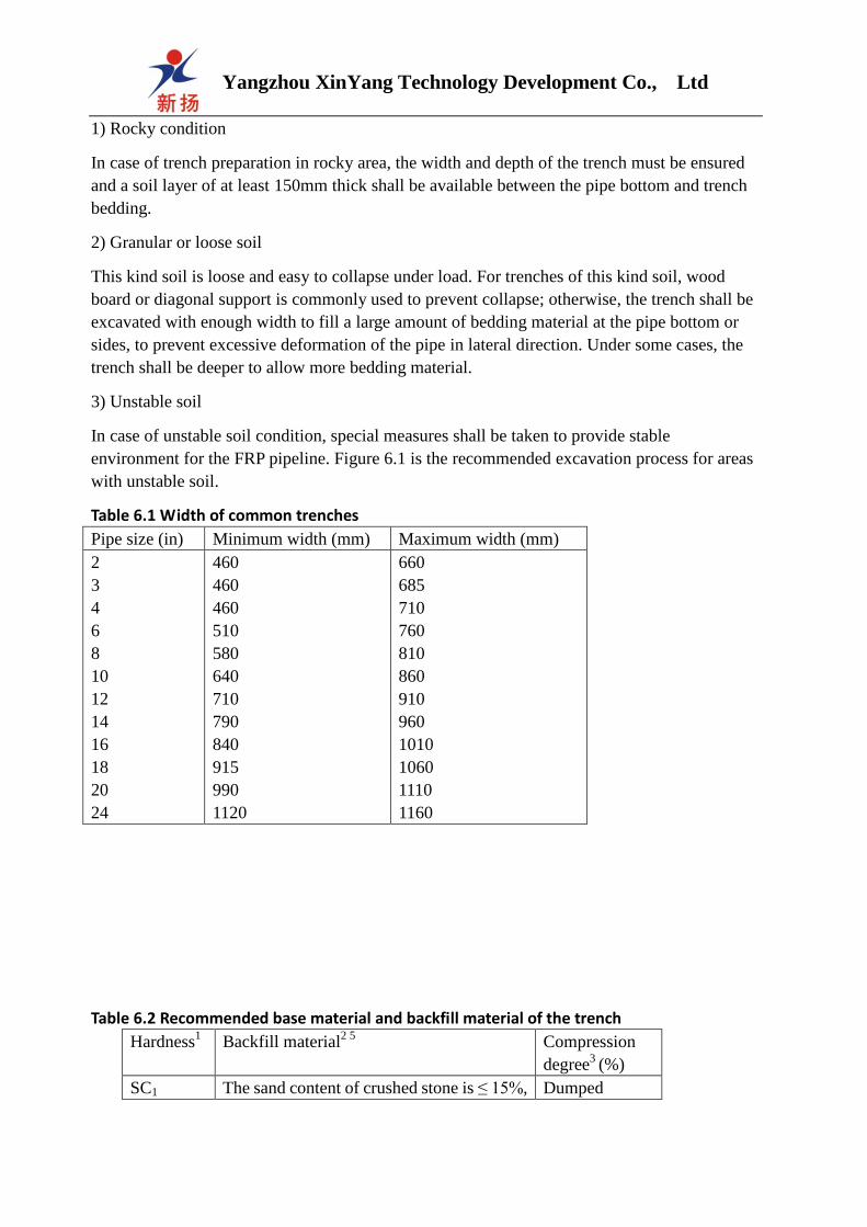
Table 6.1 Width of common trenches
Pipe size (in) Minimum width (mm) Maximum width (mm)
2
3
4
6
8
10
12
14
16
18
20
24
460
460
460
510
580
640
710
790
840
915
990
1120
660
685
710
760
810
860
910
960
1010
1060
1110
1160
Table 6.2 Recommended base material and backfill material of the trench
Hardness1 Backfill material
2 5 Compression
degree3
(%)
SC1 The sand content of crushed stone is ≤ 15%, Dumped

Yangzhou XinYang Technology Development Co., Ltd
SC2
SC3
SC3
SC4
the maximum amount through the 9.5mm
mesh is 25%, maximum content of fine
sand is 5%
Coarse grained soil with sand content ≤12%
Coarse grained soil with sand content ≥12%
Fine grained soil with sand content ≤12%
Fine grained soil with sand content ≥12%
without
compression
75-85
85-95
85-95
>95
1) AWWA M45 stiffness type
2) Maximum through-mesh rate of all soil is 25%
3) 1000psi stiffness after compressed
4) Small gravels can be used as a substitute
5) If abundant groundwater flow is foreseen, permanent trench shall be built.
压缩的自然回填土
图 6.1
150mm 渗透性织物
SC1回填土
150mm
沟底垫层(如果需要)
Figure 6.1 Pipe trench in area with soft unstable soil
3. Maximum buried depth
The maximum buried depth of trench is commonly not affected by the surface load, but is
determined by the backfill soil modulus. When stable soil of 1000psi modulus is used as
backfill, the largest backfill depth shall be usually 3660mm-6100mm, and the maximum
allowable backfill depth for soil of 700psi modulus is 5200mm. The data above is the typical
buried depth and Xinyang Company can provide design for buried depth according to practical
application of the customer.
4. Crossing highway
In case of crossing highway, protection measures shall be taken to avoid impact to the FRP
pipeline by passing vehicles and the road load. The buried depth of pipeline under stable road
foundation shall be determined as per AWWA M45. For construction under instable road
foundation or with small buried depth, concrete casing or steel casing shall be equipped to
protect the pipeline, as shown in Figure 6.2.
Compressed natural backfill
Permeable fabrics
Trench bottom cusion(if required)
Figure 6.1
SC1 backfill

Yangzhou XinYang Technology Development Co., Ltd
Figure 6.2 Typical highway crossing
7.2 Bedding and backfill
1). Trench bottom
The trench bottom is the foundation supporting the
piping system and appropriate bedding material
must be equipped for flexible FRP pipeline. The
bedding shall have a thickness of 1/4 of the pipe
diameter and in full contacting with the pipe to
provide continuous support. The proper/improper
bedding structure is shown in figure 6.3 and 6.4.
2). Backfill material
To fill the bedding material at both sides of the pipeline, the thickness of each layer shall be
150mm and then compacted to required density, and the bedding under the pipe bottom shall be
at least 150mm thick. The compaction of backfill material depends on the characteristics of
material. Soil of high percent moisture or even with water flow is not recommended as the
bedding. Xinyang Company recommends sand, gravel or crushed stone as the bedding material
for FRP pipeline. If the native soil is among the recommended backfill material listed in Table
4.0, it may be used for bedding and backfill material, unless it has a high content of humus or
frozen soil.
3) The top layer of the backfill
The top layer of the backfill shall be at least 150mm thick. The native soil can be used as the
top layer of backfill, SC5 unstable soil excluded (soil containing humus, organic material,
frozen soil and ice, etc.). The top layer backfill material shall be compacted until it reaches the
1000psi modulus specified in Table 6.0. If the dump height of a scraper bucket is greater than
460mm, the thickness of each layer dumped backfill soil shall be controlled within 300mm.
Have the backfill soil compacted layer by layer to the specified modulus, the thickness of each
layer backfill material shall not exceed the capacity of compaction equipment. Before the pipe
trench is backfilled and compacted, heavy equipment is not allowed to traverse across the
trench.
Concrete casing or steel casing
Anti-wear pad between FRP pipe and casing
Figure 6.3 Proper Figure 6.4 Improper
bedding structure bedding structure

Yangzhou XinYang Technology Development Co., Ltd
7.3. Pipe connection and place-into trench
Xinyang Key-Bonding and Key-Lock FRP pipe can be connected one by one before placed
into the trench. The elbows, tees and other FRP fittings shall be connected in the trench. To
place the pipe into trench, hanging belt and lifting hook shall be used with the pipe bending
degree not greater than the minimum bending radius of pipe. Complex underground piping
system requires hydrostatic pressure test segment by segment. The piping system with
hydrostatic pressure test qualified can be backfilled step by step as required above.
Appendix: Unit conversion and terminology
Metric unit British unit(U.S)
Length 1mm…………………………..0.03937in
1cm……………………………0.3937in
1m…………………………….39.37in
1km……………………………1093.61 yard
Area 1mm2………………………….0.00155in
2
1cm2…………………………..0.155in
2
1m2…………………………..10.764 in
2
1km2………………………….0.3861 miles2
Volume 1mm3…………………………0.000061in3
1cm3…………………………0.061in3
1L……………………………61.025in3
1m3………………………….36.314 ft
3
Capacity(fluid)1mm3…………………0.0338 ounces
1L……………………………….2.1134 pints
1L………………………………1.0567 quarts
1L……………………………….0.2642 gallons
Weight 1g……………………………….0.03527 ounces
1kg……………………………..2.2046 pints
Pressure 1kg/m………………………7.233 pound.ft
1MPa……………………………145.04 psi
1N/mm2…………………………10 bar
U.S unit system metric unit
Length 1in…………………………………25.4mm
1 ft……………………………..0.3048m
1 yard……………………………….0.9144m
1 mile……………………………..1.6093km
Area 1in2………………………………..645.16mm
2
1 yard2………………………………0.8361m
2
1 mile2……………………………2.59km
2
Volume 1 in3…………………………..16,387.2mm
3
1 ft
3……………………………0.02832m
3
1 yard3………………………………0.7646 m
3
Capacity 1 ounce………………………………29.573mm3
Terminology
Adapter: special fitting used to
connect pipe segments or fittings
which with different type of joint.
Adhesive: Corrosion resistant
material with high bonding
strength and specified component
ration.
Spigot/Socket joint: Joints with
taper longitudinal section.
Sleeve: fitting with reduced
diameter at the female end, with
threaded or bonding joint.
Compression: a pair of relative
force on the material, the circular
compression will easily collapse
the pipeline. The circular
compression of FRP pipe comes
from the end load generated from
thermal expansion.
Molding: The molding technique
of putting the prepreg into a
closed mold cavity with specific
configuration to form required
product by adding pressure and
heat curing.
Concentric reducer: The fitting
to connect two pipe segments with
different diameters and keep
coaxial of the pipes.
Contact molding: FRP fitting
molding technique of placing the
reinforcing material in the mold to
make it saturated with resin and
cured.

Yangzhou XinYang Technology Development Co., Ltd
Coupling: thick-walled fitting with bell at both ends to
connect pipes of the same diameter, the bell could be
tapered, threaded or mechanical connected.
Curing: The process to make the thermosetting resin
hardened via chemical reaction by heating.
Curing stage: the three curing stages of thermosetting
resin, namely, A stage –flowing- B stage – gelling -C
stage - fully cured.
Curing time: The time required for the thermosetting resin to be hardened by chemical
reaction till maximum intensity is achieved,
depending on the temperature and the nature of the material.
Curing agent: The chemical agent mixed with thermosetting resin to make the resin molecular
chain interconnected with each other.
Epoxy resin: Thermosetting resin containing epoxy group in the molecular structure.
Scarfed fitting: have the cut pipe segments with required configuration and have the joints
reinforced via hand lay-up or filament wound to form a fitting, which is called Scarfed
fitting .
Filament wound: The manufacture process for FRP pipe and fitting which is winding the glass
roving on mandrel to form the product according to the specified winding pattern . The glass
content and pattern could be precisely controlled.
Filler: the dispersant, pigment, inert additives, quartz sand, etc.
Fitting type: the fitting types classified according to the manufacture process, such as the
molded fitting, scarfed fitting , winding fitting and hand lay-up fitting, etc.
Gel time: the time required from the resin begins to react till it shows the rubber elastic state.
Pipe guide: The device allowing the free movement of pipe along the axial direction, with the
constraint lagging behind the movement of pipeline.
Hardener: the joint name for accelerator, catalyst and curing agent, used to accelerate the
reaction and final hardening of the resin.
Heating blanket: the electrical device wrapping around the pipe and fitting to provide heat and
shorten the curing time.
Hydrostatic test: the test with water at required pressure for the pipeline upon the completion
of installation, leakage shall be checked at the joints and pipe body.
Impact resistance: the capacity of absorbing the impact energy without damages to the pipe.
1 pint………………………………1.47317L
1 quart………………………………0.94633L
1 gallon………………………………3.78533L
Weight 1 grain……………………………….0648g
1 ounce………………………………28.35g
1 pound…………………………………0.4536kg
Pressure 1 in. pound……………………….0.13826kg/m
1psi…………………………………0.006894MPa

Yangzhou XinYang Technology Development Co., Ltd
Connection: the measures of connecting two pipe segments, including spigot/socket , threaded
coupling or mechanical connections of different ways.
Joint: the connecting section of fixed-length pipe, in the form of spigot/socket bonding joint,
threaded joint or coupling joint etc.
Liner: the resin-rich layer of 0.5mm-1.5mm thick in the pipe inner wall, the reinforcing
material is usually polyester veil or glass mat. The liner could realize super chemical resistance
and cracking resistance of the pipe.
Locking: having the fitting surface between spigot and socket contacted tightly to avoid
rotation.
Matrix: the material bonding the reinforced material or filler together, it could be either
thermoplastic resin or thermosetting resin.
Mechanical power: the power imposed to make the spigot/socket joint tightly fitted during
pipe installation.
Polyester resin: the thermosetting resins with styrene as the coupling agent, of which the vinyl
resin is a special polyester resin. The polyester resin is usually divided of o-benzene type and
m-benzene type, with application depending on the performance requirement of the pipes.
Pot life: the period suitable for operation after the thermosetting resins or adhesives are mixed
with curing agent.
Pressure rating: the maximum long-term work pressure of the pipeline specified by the
manufacturers, refer to the working pressure, pressure rating, and design pressure.
Reinforcement: the fiberglass, carbon fiber and synthetic fiber, etc., that enhances the strength
and hardness of the composite. The performance of fiber plays a leading role in affecting the
mechanical properties of composite. The fiber reinforcement mainly include:
1: Chopped fiber: 3-5mm long short fibers that are cut from continuous fiberglass.
2: Chop strand mat: the sheet material composed of short fiberglass (or other fiber) arranged
randomly and bonded by the adhesives.
3: Surface mat: the porous sheet material made of fiberglass or synthetic fiber and used for the
liners of pipes or fittings.
4: Yarn: the fiber product made of one strand or strands of fibers and used for filament winding
process.
5: Yield: the yardage of per pound of fiber.
Saddle: the fitting bonding to the pipe wall to form branch.
Shelf life: the material storage time till failure.
Straight spigot/socket joint: a type of joint of which the spigot end is taper-free and the socket
is designed with a stop edge.

Yangzhou XinYang Technology Development Co., Ltd
Partition: the wood placed between pipe layers of the pipe stack, to avoid point load to the
pipe.
Stress: the force acted on the unit cross section area of the material, with the unit of psi or MPa,
which is different from the hydrostatic pressure unit psig.
Support span: the recommended maximum distance between two adjacent pipe supports.
Surge pressure: instantaneous pressure fluctuations which are usually caused by water
hammer.
Thermal conductivity: heat transfer from the high-temperature surface to the low-temperature
surface within the pipe.
Thermal expansion: the material (pipe) size change caused by temperature rise, and material
(pipe) contraction will be led by temperature dropping.
Thermosetting resin: the insoluble and infusible resin system that is formed and cured
through heating the resin or adding chemicals to the resin. The typical thermosetting resins are
vinyl resin, epoxy resin, phenolic resin and unsaturated polyester resin, etc.
Impact : the force generated via the flow direction changing of the liquid column within the
pipeline, as well as the axial end load generated at the fitting and valve due to static pressure.
Torque: the rotation torque forcing the pipe to rotate, equaling to the force multiplying the
distance from the force origin to the rotation axis.