Embed Size (px)
Citation preview

INSTALLATIONMANUAL
ModelsFWT02AATNMV1FWT03AATNMV1FWT04AATNMV1FWT05AATNMV1FWT06AATNMV1
EnglishInstallation manualChilled Water Fan Coil Units


1
En
gli
s h
OUTLINE AND DIMENSIONS
Indoor Unit
Dimension A B C D E F G H I J K L M N O
FWT02AATNMV1 799 260 198 379 246 185 124 8 56 50 350 379 50 128 132
(31,5) (10,2) (7,8) (15,0) (9,7) (7,3) (4,9) (0,3) (2,2) (2,0) (13,8) (15,0) (2,0) (5,1) (5,2)
FWT03AATNMV1 / 899 260 198 590 246 185 124 8 56 50 435 495 50 128 132
FWT04AATNMV1 (35,4) (10,2) (7,8) (23,2) (9,7) (7,3) (4,9) (0,3) (2,2) (2,0) (17,1) (19,5) (2,0) (5,1) (5,2)
A
TOP VIEW
FRONT VIEW SIDE VIEW
B
I I
C
MJ
INSTALLATION PLATE
SEE DETAIL A
WATER OUTLET
WATER INLET
K DETAIL AL
F D G
ON
EH

2
Indoor Unit
A
TOP VIEW
FRONT VIEW SIDE VIEW
BI I
C
MJ
INSTALLATION PLATE
INSTALLATION PLATESEE DETAIL A
WATER OUTLET
WATER INLET
K
DETAIL A
L
F D G
ON
EH
A
CENTER LINE
B
Dimension A B C D E F G H I J K L M N O
FWT05AATNMV1 / 1060 310 220 912 294 99 51 8 48 43 369 453 160 138 160
FWT06AATNMV1 (41,7) (12,2) (8,6) (35,9) (11,6) (3,9) (2,0) (0,3) (1,9) (1,7) (14,5) (17,8) (6,3) (5,4) (6,3)
3
En
gli
s h
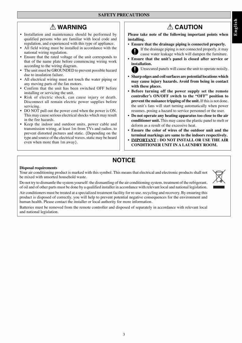
SAFETY PRECAUTIONS
NOTICEDisposal requirementsYour air conditioning product is marked with this symbol. This means that electrical and electronic products shall notbe mixed with unsorted household waste.Do not try to dismantle the system yourself: the dismantling of the air conditioning system, treatment of the refrigerant,of oil and of other parts must be done by a qualified installer in accordance with relevant local and national legislation.Air conditioners must be treated at a specialized treatment facility for re-use, recycling and recovery. By ensuring thisproduct is disposed of correctly, you will help to prevent potential negative consequences for the environment andhuman health. Please contact the installer or local authority for more information.Batteries must be removed from the remote controller and disposed of separately in accordance with relevant localand national legislation.
! CAUTIONPlease take note of the following important points wheninstalling.• Ensure that the drainage piping is connected properly.
If the drainage piping is not connected properly, it maycause water leakage which will dampen the furniture.
• Ensure that the unit’s panel is closed after service orinstallation.
Unsecured panels will cause the unit to operate noisily.
• Sharp edges and coil surfaces are potential locations whichmay cause injury hazards. Avoid from being in contactwith these places.
• Before turning off the power supply set the remotecontroller’s ON/OFF switch to the “OFF” position toprevent the nuisance tripping of the unit. If this is not done,the unit’s fans will start turning automatically when powerresumes, posing a hazard to service personnel or the user.
• Do not operate any heating apparatus too close to the airconditioner unit. This may cause the plastic panel to melt ordeform as a result of the excessive heat.
• Ensure the color of wires of the outdoor unit and theterminal markings are same to the indoors respectively.
• IMPORTANT : DO NOT INSTALL OR USE THE AIRCONDITIONER UNIT IN A LAUNDRY ROOM.
! WARNING• Installation and maintenance should be performed by
qualified persons who are familiar with local code andregulation, and experienced with this type of appliance.
• All field wiring must be installed in accordance with thenational wiring regulation.
• Ensure that the rated voltage of the unit corresponds tothat of the name plate before commencing wiring workaccording to the wiring diagram.
• The unit must be GROUNDED to prevent possible hazarddue to insulation failure.
• All electrical wiring must not touch the water piping orany moving parts of the fan motors.
• Confirm that the unit has been switched OFF beforeinstalling or servicing the unit.
• Risk of electric shock, can cause injury or death.Disconnect all remain electric power supplies beforeservicing.
• DO NOT pull out the power cord when the power is ON.This may cause serious electrical shocks which may resultin the fire hazards.
• Keep the indoor and outdoor units, power cable andtransmission wiring, at least 1m from TVs and radios, toprevent distorted pictures and static. {Depending on thetype and source of the electrical waves, static may be heardeven when more than 1m away}.

4
Water Drainage PipingThe indoor drain pipe must be in a downward gradient forsmooth drainage. Avoid situations that are likely to cause waterto leak.
Correct
EndDippedInto Water
WaterLeaking
WaterLeaking
WaterLeaking
Wrong Wrong Wrong
Drain
Water Drainage
WaterRetention
Water Piping ConnectionThe indoor unit is equipped with water outlet and inlet threaded connection. There is an air-vent for air purging that is fitted at theoutlet water header.3 ways valve is required for cycling off or bypass the chilled water.Black steel pipe, polyuthrene pipe, PVC pipe and copper tube are recommended in field installation.All types of piping and connection must be insulated by polyurethane (ARMAFLEX type or equivalent) to avoid condensation.Do not use contaminated or damaged pipe and fitting for installation.Some main fitting components are needed in the system to enhance the capacity and ease of service, such as gate valve, balancingvalve, 2 ways or 3 ways valve, filter, strainer, etc.
Gate Valve Three Way Valve Gate Valve Two Way Valve Gate Valve
Chiller Gate Valve
Good Controlling Bad Controlling
Gate Valve
FCUFCUFCU
Worst Controlling
Gate Valve
The indoor unit must be installed in such a way so as to preventshort circuit of the cool discharged air with the hot return air.Please follow the installation clearance shown in the figure.Do not place the indoor unit where there could be direct sunlightshining on it. Also, this location must be suitable for pipingand drainage, and be away from doors or windows.
Screw position in the wall
72.0
Centre Line
Ø 65.0 mm Hole in the wall
Screw position in the wall
Ø 65.0 mm Hole in the wall
Maintenance &Servicing Space
Air FlowDirection
Hig
her T
han
Eye
Leve
l
50.0 mm 50.0 mm
50.0
mm
INSTALLATION OF THE INDOOR UNIT
Mount The Unit Onto The Installation PlateHook the indoor unit onto the upper portion of theinstallation plate (Engage the two hooks at the rear top of theindoor unit with the upper edge of the installation plate). Ensurethat the hooks are properly seated on the installation plate bymoving it to the left and right.
1. Hook the unit onto the installation plate.
Hole With Cone Drill
Indoor Side Outdoor Side

5
En
gli
s h
• All wires must be firmly connected.• All wires must not touch the water piping, or any moving parts
of the fan motor.• The connecting wires to the indoor unit must be clamped on
the wire clamps as shown in the figure.• The power supply cord must be equivalent to H05VV-F (60227
IEC 52 or 60227 IEC 53) which is the minimum requirement,and to be used in protective tube.
Wire Clamp
InterconnectionCable
Power SupplyCable
FWT02~06AATNMV1
FCU 3
VALVE N2 N1 L
FCU 2
VALVE N2 N1 L
FCU 1
VALVE N2 N1 L
NTSR
3WV 3WV3WV
x1 x2 x3
3WV
x1, x2, x3
Chiller
ELECTRICAL WIRING CONNECTION
IMPORTANT : The figures shown in the table are for information purpose only. They should be checked and selectedto comply with the local/national codes of regulations. This is also subject to the type of installationand conductors used.A main switch or other means for disconnection, having a contact separation in all poles, must beincorporated in the fixed wiring in accordance with relevant local and national legislation.
Model FWT02AATNMV1 / FWT05AATNMV1 /FWT03AATNMV1 / FWT06AATNMV1FWT04AATNMV1
Voltage range 220V – 240V/1Ph / 50Hz +
Power supply cable size mm2 1.5 1.5Number of wire 3 3
Recommended fuse A 2 2
3 way valve
Relay (220-240V, 10A)

6
MODEL: FWT05AATNMV1 / FWT06AATNMV1
MODEL: FWT02AATNMV1 / FWT03AATNMV1 / FWT04AATNMV1
Note: Unit comes in standard heatpump and for valve application.
ORANGE (LO)
BROWN (MED)
BLACK (HI)
VALVE N2 N1 L
TO 3 WAY VALVE
220~240V AC1 PHASE 50Hz
AS
FM
YELLOW/GREEN
INDOOR COIL THERMISTOR
ROOM THERMISTOR
IR BOARD
SLEEP COOL/HEAT TIMER ION
DISPLAY BOARD
BLUE BLUE
FAN MOTORCAPACITORRED
BLUE
RED
BLUEPURPLE
- WITH JUMPER FOR HEAT PUMP- WITHOUT JUMPER FOR COOLING ONLY- WITH JUMPER FOR VALVE APPLICATION- WITHOUT JUMPER FOR VALVELESS APPLICATION
PART NO: 08 02 4 091934
CAUTION !
FM : FAN MOTORAS : AIR SWING MOTOR
ORANGE (LO)
BROWN (MED)
BLACK (HI) ASFM
BLUE
INDOOR COIL THERMISTOR
ROOM THERMISTORSLEEP COOL/HEAT TIMER ION
DISPLAY BOARD
FAN MOTORCAPACITORRED
VALVE N2 N1 L
LNE
YELLOW/GREEN
SWITCH BOARD
IR BOARD
TO 3 WAY VALVE- WITH JUMPER FOR HEAT PUMP- WITHOUT JUMPER FOR VALVE APPLICATION
- WITH JUMPER FOR VALVE APPLICATION- WITHOUT JUMPER FOR VALVELESS APPLICATION
PART NO: 08 02 4 091938
CAUTION !
FM : FAN MOTORAS : AIR SWING MOTOR
LNE
220~240V AC1 PHASE 50Hz
WIREDCONTROLLER
WIREDCONTROLLER
FIELD INSTALLATION
FIELD INSTALLATION

7
En
gli
s h
AIR CONDITIONER UNIT OPERATION
Dry Mode• When the air humidity is high, the unit can operate in dry
mode. Press <MODE> button and choose <DRY>.• If the room temperature is 2°C/35.6°F higher than the set
temperature, the air conditioner will operate under coolingmode until it reaches within the 2°C/35.6°F range ofdifference compared to the set temperature before itconverts to dry mode.
• If the room temperature is within the 2°C/35.6°F range ofdifference compared to the set temperature, it willdirectly operate under dry mode.
• The unit will operate at LOW speed under dry mode.
Horizontal Air Flow Control• For more effective air circulation, you can manually adjust
the air discharge grille to the left or right.• During cool mode operation and dry mode operation, do
not direct the air discharge louver downwards for too long.If operating continues in this way, condensation may occuron the louver, thus resulting in drippings.
Horizontal
Coo
ling
Dry
25˚C / 77˚F
Fan Speed And Rated Cooling Capacity• The rated cooling capacity is provided at the maximum fan
speed.• The cooling capacity is lower when the unit is operating at
MEDIUM and LOW fan speed.
IR Signal Receiver
When an infrared remote control operating signal has beentransmitted, the signal receiver on the indoor unit will makea <beep> sound to confirm acceptance of the signaltransmission.
Cooling Unit / Heat Pump Unit
The table shows the LED indicator lights for the air conditionerunit under normal operation and fault conditions.The LED indicator lights are located at the middle of the airconditioner unit.
INDICATOR LIGHTS
LED Indicator Lights For Cooling/ Heat Pump Unit
LED indicator lights
IR Receiver
Sleep Mode Cool Timer Ionizer
LED Indicator Lights : Normal Operation And Fault Conditions For Cooling / Heat Pump Unit
Normal Operation / Fault Indication Action
Cool mode –
Heat mode –
Timer on –
Sleep mode on –
Ionizer on –
Fan mode on –
Dry mode on –
Room air sensor contactLoose / Short
Call your dealer
Indoor coil sensor contactCall your dealerLoose/Short
Pipe water temperature poor Call your dealer
Pipe water temperature bad Call your dealer
COOL/HEAT(GREEN/RED)
Red
3 times
1 time
ON ON or OFF Blinking
2 times
Green
1 time
Note: Ionizer is optional depending on availability.

8
! CAUTION1. The electrostatic air purifying and deodorizing filter
should be replaced once every 6 months or when thefilter changes color to brownish, whichever is sooner.
2. Used dusty filters should be disposed and shouldn't be reused,even if it has been cleaned and washed.
3. The filter is a consumable part which you can purchasefrom your air conditioner dealer.
4. Use the new filter immediately once it has been takenout from its sealed packing. Do not unpack the newfilter too early before it is actually used as this maydecrease its deodorizing effect.
AUTO RANDOM RE-START FUNCTION
If there is a power cut when the unit is operating, it will automatically resume the same operating mode when the power is restored.(Applicable only to units with this feature.)
OPERATING RANGE
Operating Limits:Thermal carrier : WaterWater temperature : 5 ~50°CMaximum water pressure : 16 barAir temperature : (as below)
Cooling ModeTemperature Ts °C/°F Th °C/°F
Minimum indoor16.0 / 60.8 11.0 / 51.8temperature
Maximum indoor32.0 / 89.6 23.0 / 73.4temperature
Minimum outdoor16.0 / 60.8 -temperature
Maximum outdoor46.0 / 114.8 -temperature
Heating Mode
Ts: Dry bulb temperature. Th: Wet bulb temperature.
Temperature Ts °C/°F Th °C/°F
Minimum indoor16.0 / 60.8 -temperature
Maximum indoor30.0 / 86.0 -temperature
Minimum outdoor-5.0 / 23.0 -6.0 / 21.2temperature
Maximum outdoor24.0 / 75.2 18.0 / 64.4temperature
SERVICE AND MAINTENANCE
Maintenance Procedures
1. Remove any dust adhering to the filter by using a vacuum cleaner or wash inlukewarm water (below 40°C/104°F ) with a neutral cleaning detergent.
2. Rinse the filter well and dry before placing it back onto the unit.
3. Do not use gasoline, volatile substances or chemicals to clean the filter.
1. Clean any dirt or dust on the grille or panel by wiping it off with a soft clothsoaked in lukewarm water (below 40°C/104°F) and a neutraldetergent solution.
2. Do not use gasoline, volatile substances or chemicals to clean theindoor unit.
Period
At least once every 2weeks.
More frequently ifnecessary.
At least once every 2weeks.
More frequently ifnecessary.
Service Parts
Indoor air filter
Indoor unit

9
En
gli
s h
1 Off the unit.
2 Unscrew the air discharge housing.
3 Flip open the air discharge housing.
4 Clean the blower.
5 Close the air discharge housing and tighten it with screw.
! CAUTION• Do not operate any heating apparatus too close to the air conditioner unit. This may cause the plastic panel to melt or deform as a result
of the excessive heat.
WHEN THE UNIT IS NOT USED FOR AN EXTENDED PERIOD OF TIME
Operate the unit for 2 hourswith the following setting.
Operating mode : coolTemperature : 30°C/86°F
Remove the power plug.If you are using an independentelectric circuit for your unit,cut off the circuit.Remove the batteries in theremote control.

10
If any malfunction of the air conditioner unit is noted, immediately switch off the power supply to the unit. Checkthe following fault conditions and causes for some simple troubleshooting tips.
TROUBLESHOOTING
Fault
1. The compressor does not start opearate after 3 minutes from start-ing the air conditioner unit.
2. The air conditioner unit does not operate.
3. The air flow is too low.
4. The remote control display is dim.
5. Discharge air flow has bad odor.
6. Condensation on the front air grille of the indoor unit.
7. Water flowing out from the air conditioner unit.
If the fault persists, please call your local dealer/serviceman.
Causes
- Protection against frequent starting. Wait for 3 to 4 minutes forthe compressor to start operate.
- Power failure, or the fuse need to be replaced.
- The power plug is disconnected.
- It is possible that your delay timer has been set incorrectly.
- If the fault persist after all these verifications, please contact theair conditioner unit installer.
- The air filter is dirty.
- The doors or windows are open.
- The air suction and discharge are clogged.
- The regulated temperature is not high enough.
- Battery flat.
- The batteries are placed incorrectly.
- Odors may be caused by cigarettes, smoke particles, perfume etc.which might have adhered onto the coil.
- This is caused by air humidity after an extended long period ofoperation.
- The set temperature is too low, increase the temperature settingand operate the unit at high fan speed.
- Check the condensate evacuation.

MEMO


Head office: Zandvoordestraat 300, B-8400 Oostende, BelgiumUmeda Center Bldg., 2-4-12, Nakazaki-Nishi,Kita-ku, Osaka, 530-8323 Japan
Tokyo office:JR Shinagawa East Bldg., 2-18-1, Konan,Minato-ku, Tokyo, 108-0075 Japanhttp://www.daikin.com/global/
Part No.: R08019029236