Embed Size (px)
Citation preview

Installation Manual
(For undertile heating element)
Please read the ENTIRE Installation Manual before attempting to do the installation. Incorrect installation could damage the cable and therefore make your warranty invalid

Page • Floor Preparation – Step 1 11 • Mark the floor for element position –
Steps 2 & 3 12
• Lay out heating element and secure with fixing tape- Steps 4 & 5
13
• Cover with screed and test the heating element – Steps 6 & 7
16
• Connection and testing of the continuity alarm – Step 8
17
• Tiling – Step 9 18 • Controller connection – Step 10 19
Your Warmtech Undertile Heater has
been designed so that installation is
quick and straight forward, but as with
all electrical systems, certain
procedures must be strictly followed.
Kit contents
Warmtech Undertile Heating element
including element continuity alarm
Adhesive spray
Adhesive tape
Thermal screed
Controller
Manual
Warmtech Heating Systems accepts no liability,
expressed or implied for any loss or consequential
damage suffered as a result of installations which in
any way contravene the instructions that follow.
If these instructions are followed, you should have no problems. However if you do require help at any stage, please call our Free helpline:
Warmtech helpline: 1300 138 126 You can also find a copy of this manual, wiring instructions, a list of frequently asked questions and more helpful information on our website: www.warmtech.com.au.
3
4
6
7
8
11
20
22
Contents
2
5
10
9
Do’s & Don’ts
Simple steps to luxurious warmth
Do not damage the heating element.
Sizing Guide
Configuration Notes
Prewiring of Electrical Installation
Technical Notes
Calculate the actual spacing of the
heating element.
Installation Steps 1-10
Tiler Instructions
Product Warranty

Do and don’ts
DO carefully read this installation manual before commencing installation.
DO ensure the floor surface is clean and dry before proceeding.
DO plan the wire layout and stick to recommended wire spacing and perimeters.
DO Space the element evenly over the floor.
DO Plan post-tiling drilling (eg for fixing sanitary ware, door stops) so as not to damage the wiring.
DO maintain a gap between heating wire runs of at least 50mm at all times.
DO make sure that ALL the element wire is positioned under the tiles in the installation.
DO Protect the element with cardboard or hardboard between installation and tiling.
DO use tile adhesives and grouts suitable for use with underfloor heating. (Check with Warmtech)
DO check that the heater is working immediately before commencing tiling.
DO take particular care when tiling not to dislodge or damage the heater element.
DO Ensure that each tile is solidly bedded in the adhesive, with no gaps or voids.
DO If in doubt about the suitability of the sub-floor to be heated, check with your local tile shop,
tiler or call the Warmtech technical helpline.
DON’T cut or attempt to shorten the element wire at any time.
DON’T commence installation on a concrete floor that has not fully cured.
DON’T allow traffic over the installed heater before tiling.
DON’T remove the heating element from the spool other than during installation.
DON’T allow the heating wires to cross over or touch each other at any point.
DON’T store tiles, sharp or heavy objects on any of the wiring whilst tiling.
DON’T commence tiling before testing the Warmtech Heating System using the cable alarm.
DON’T switch on the installed heating system until tile adhesive has fully dried – 7 days minimum.
DON’T install the heating wire on stairways or up the walls.
Warning Once the heating wire has been installed avoid all traffic over the wire until the floor has been covered by sand and cement. Do not install the heating wire until the floor is ready to be tiled. Immediately prior to tiling, test the heating wires as specified on page 13 to check it has not been damaged.
If you are in any doubt, call the Warmtech helpline on 1300 138 126.
3

Simple Steps to Luxurious Warmth
4

DO NOT DAMAGE THE HEATING ELEMENT
Please check the sizing guide to ensure that you have the correct heater(s) for the
area you wish to heat.
Your Warmtech Undertile heating element is one continuous resistance wire with
electrical conducting wires connected to each end. It must not be cut, shortened or
lengthened. Once the heater has been installed, avoid all traffic over the heating
element until the floor has been tiled. If the floor is not being tiled immediately, a
sheet of cardboard or hardboard should be laid over the heater as interim protection.
Immediately prior to tiling Test the Heater to check that it is working (specified on
Page 16 ).
IF THE HEATER IS NOT WORKING DO NOT COMMENCE TILING,
CALL WARMTECH : 1300 138 126.
5

Element Total Ohms (@ 20°C)
Cable Length
Coverage in sqm (at wire centers of
…(mm) ± 10%
60 85 100
Power Density (watts per sqm)
± 5%
60 85 100
UT200 264 ohms 16.5m 0.90 1.22 1.42 222 163 140
UT300 176 ohms 25.0m 1.29 1.79 2.09 232 167 144
UT400 132 ohms 33.5m 1.76 2.45 2.86 227 163 140
UT500 105 ohms 41.5m 2.18 3.06 3.57 229 164 140
UT650 82 ohms 54.0m 2.91 4.07 4.76 223 159 136
UT800 66 ohms 66.5m 3.60 5.06 5.91 223 159 136
UT1000 52 ohms 83.5m 4.56 6.41 7.50 219 156 133
UT1250 42 ohms 105.0m 5.82 8.18 9.58 216 154 132
UT1500 33 ohms 125.0m 6.96 9.79 11.47 215 153 131
UT2000 25 ohms 166.5m 9.37 13.19 15.46 211 150 128
UT2500 21 ohms 208.5m 11.85 16.69 19.56 214 152 129
UT3000 16 ohms 250.0m 14.31 20.14 23.61 210 149 127
Sizing Guide
For larger or different area sizing – please contact the Warmtech technical helpline on
1300 138 126.
Notes:
These are nominal specifications only.
Coverage table is by calculation only – actual wire layout on the floor may have an
effect on the actual coverage obtained. The table shows the area in sqm that any cable
will cover at various wire centres eg if a UT1000 is laid up with the runs 85mm apart, a
total heated area of 6.41sqm should be achieved.
The power density table shows the watts per sqm of the heated area – the higher the
power density the greater the temperature rise on the tiled surface.
6

Configuration Notes
Whilst the installation instructions only make provision for the heating elements to be
installed in a set configuration, there are many instances where departure from this
configuration may be desirable. Below are a few drawings illustrating such instances:
In each of the above examples, the floor space is heated using different wire configurations to
suit the particular layout of the room. Most layouts will differ with every job.
7

Pre-wiring of Electrical Installation – Wall mounted thermostat
8

Technical Notes
To fully utilize the long-term durability of your tiles, whether heated or not, it is
important that the design and construction of the sub floor is carried out correctly.
The sub floor must be sufficiently rigid to support the ultimate weight that it will have
to bear without movement or deflection. Wherever a timber sub floor is to be heated
and tiled it is strongly recommended that a fibre cement sheet is installed prior to
heating and tiling.
Waterproofing (if required) or movement control joints should be done prior to the
installation.
The installation should comply with the following Codes of Practice:
Electrical Codes of Practice AS/NZS 3000:2000
The choice of products for sub floor preparation and tile fixing will vary depending on
the existing sub floor, preferred tiling system and choice of tile.
If in doubt please consult with your tiler, tile supplier or adhesive supplier.
9

1. Work out the actual sqm to be heated (see grey shaded area) i.e. 3.53sqm.
2. Divide this figure by the length of the wire to be used per the sizing guide
3.53m2 ÷ 41.5m = 0.085.
3. Multiply this figure by 1000. 0.085 x 1000 = 85mm apart is your wire spacing.
Summary: 3.53m2
41.5m of wire
= 0.085 x 1000 = 85mm apart
Calculate the actual spacing of the heating element on the floor
Helpful Hints:
The element is a continuous wire that must not be shortened or lengthened. Even
spacing of the wire will ensure an even temperature of your tiles.
The adhesive spray ensures that the adhesive tape holds in place. Allow 10
minutes for curing before attempting to adhere tape.
All the elements are marked with a halfway marker for an indication of how your
installation is progressing.
For a successful long installation life, your floor should be clean, dry and stable
(wooden floors) or fully cured (concrete floors).
10
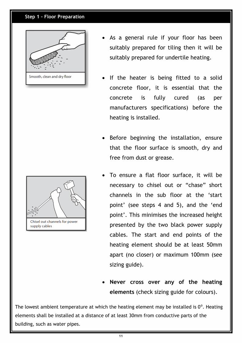
Step 1 – Floor Preparation
As a general rule if your floor has been
suitably prepared for tiling then it will be
suitably prepared for undertile heating.
If the heater is being fitted to a solid
concrete floor, it is essential that the
concrete is fully cured (as per
manufacturers specifications) before the
heating is installed.
Before beginning the installation, ensure
that the floor surface is smooth, dry and
free from dust or grease.
To ensure a flat floor surface, it will be
necessary to chisel out or “chase” short
channels in the sub floor at the ‘start
point’ (see steps 4 and 5), and the ‘end
point’. This minimises the increased height
presented by the two black power supply
cables. The start and end points of the
heating element should be at least 50mm
apart (no closer) or maximum 100mm (see
sizing guide).
Never cross over any of the heating
elements (check sizing guide for colours).
11
The lowest ambient temperature at which the heating element may be installed is 0⁰. Heating
elements shall be installed at a distance of at least 30mm from conductive parts of the
building, such as water pipes.

Steps 2 and 3 – Mark the floor for element position
Calculate in square metres the actual size
of the area to be heated. Then, using the
sizing/calculation guide on pages 6 and 10,
establish the actual element spacings.
Using a fibre tipped pen mark a start point
no further than 1.50m from the power
supply. The start point should be positioned
as close as possible to the power supply.
Mark all the outer corners of the heated
area observing the perimeter distances and
join the corners up to form a marked out
perimeter.
Mark up the spacing intervals for the
element wire following the sizing guide plus
your actual calculation. The spacing
interval between the element wires must
be at least 50mm apart. The maximum
spacing interval that is recommended is
100mm.
Spray the floor with the adhesive spray
along areas where the cable loops around,
or where the element will require taping in
place. The spray adhesive acts as a primer
for the tape and should only be used where
the element is to be taped to the floor.
Allow to cure for approximately 10 minutes.
12

Installation Step 4 and 5 – Lay out heating element and secure with fixing tape.
Gently unroll the power supply cable from the
spool. After 3 metres of black cable has been
removed, you will reach the point at which the
power supply cable joins the heating element
wire (which is of a different colour).
The join of the power supply cable and the
heating cable should be taped to the floor at
the start point (which is the first of the
chiselled channels).
Following the perimeter markings on the floor,
lay out the heating element wire, taping down
at each corner. The element wire should run
from the start point in a U shape to the
furthest corner from the start point.
Once the element wire has been laid out
around the perimeter, start laying out the
heater wire in parallel lines back and forth
across the main body of the area to be heated.
Using the spacing markings, tape down the
element to the floor with strips of the
adhesive tape (which has been supplied) over
the pre sprayed areas. The tape strips should
be about 25mm (1 inch) long.
You will also note a ½ way marker indicating
that you have used up ½ the length of the
heating element. Check the coverage of the
floor already completed to gauge your end
result.
Once the floor has been marked up, the element wire can be laid out.
13

When you have completed about 90% of the
element layout, gently unroll the remaining
wire and the second power supply cable
(black) from the spool. At the end point where
the power supply cable meets the heating
element you will find another join. Tape this
join to the end point (which is the second
chiselled channel), at least 50mm apart from
the start point join that you taped down
previously.
You will be left with a coil of unsecured
element. This unsecured element should be
laid out in reverse order i.e. starting from the
end point and working backwards to the last
point at which the element was taped down.
In order to achieve even coverage of the
balance of the area to be heated, you may at
this stage need to adjust some of the element
spacing that you previously secured.
This can be achieved by untaping a few of the
previous runs of element that you taped down,
and re-fixing them at wider or narrower
intervals. You may wish to alter the element
layout to fit your particular requirements.
Where there are irregularities of shape you
can lay out the element to provide warmth
around toilets, etc.
14

This is quite acceptable provided that:
a. The element is spaced at least 50mm
apart at all times. Not closer.
b. The element should never cross over.
c. Never allow the heating element to be
within the wall cavity, the black ‘power
supply leads’ only.
Once the laying of the element is complete
meaning the black leads are both back to the
starting point, these will need to be
carefully pulled up within the wall cavity
using the draw wire.
If the standard controller has been
upgraded to include a floor sensing probe,
the floor sensing probe must be installed
at this stage.
The floor probe (temperature sensor) is to
be laid as far into the centre of the floor as
possible (positioned exactly between 2
runs of heating elements – this is very
important for accuracy of temperature
control), still ensuring that the floor probe
lead (3 metres in length) can reach the
controller position up the wall.
15

Installation Step 6 – Cover the heating element with thermal screed
Installation Step 7 – Testing of the heater (Prior to and during tiling/tiling procedures)
Fit the power supply cables into the channels
and secure with fixing tape. Remove all
debris and chippings from the floor.
Check the subfloor, as certain floor may
require priming prior to the levelling screed
being laid.
Mix and apply the screed as per the
manufacturer’s instructions.
Depending on your tiler’s requirements, they
may wish to apply a self levelling screed over
the heating elements for ease of tiling.
Allow 24-48 hours before commencing tiling.
Check the resistance on the heater, using a
multi meter and confirm the reading against
factory specifications (label on the cardboard
spool).
Test the heating element using an insulation
tester (min. Voltage 500V)
Connect the continuity tester (supplied with
each heating element). Follow the connection
instructions.
If the alarm sounds during the tiling
procedure, stop all work and call Warmtech
on 1300 138 126.
After the tiling and grouting procedure has
been completed, the checks 1 and 2 need to
be repeated.
Your Warmtech Undertile heater has been comprehensively tested prior to
sale. You should retest the heater by using the following method.
16

Installation Step 8 – Connection and testing of the Continuity alarm
Ensure that the batteries are correctly
installed.
Test by turning the switch to the ON position
and ensure that the audible alarm sounds. If
the alarm sound cannot be heard, please call
1300 138 126 for technical assistance.
Turn to the OFF position during connection to
the heating element, and then turn it ON.
Note: When the heating element is connected to
the tester and turned ON, there should be no
alarm sound audible.
17

Installation Step 9 - Tiling
The tile adhesive and grout should be suitable
for use with underfloor heating. For further
information refer to the Technical Notes
section on Page 9.
Where possible when tiling, gently comb the
adhesive in straight lines in the same direction
as the runs of the heating element. If possible
use a plastic trowel. Where possible, combing
the adhesive at right angles to the element
should be avoided.
Use sufficient adhesive to ensure that there
are no voids or hollows under the tile.
If a tile has been positioned incorrectly, care
should be taken not to damage the heating
element when lifting the tile.
Do not store or cut tiles on top of the heater.
Do not allow chippings or dust to contaminate
the floor during tiling. Care must be taken not
to damage the heating element during the
tiling process.
Use a piece of carpet or cardboard as a ‘crawl
board’ to prevent the heater being damaged
by your feet or knees during the tiling process.
If possible, periodically test the heater during
tiling. If the heater is not working, DO NOT
CONTINUE, call Warmtech Technical Support
on 1300 138 126.
The thickness of covering materials shall be at least 5mm.
The maximum thermal resistance between the heating unit and the room is
0.333per sqm K/W.
18

Installation Step 10 – Controller Connection
Grout the floor as soon as possible as per the
adhesive manufacturer’s instructions (Extra
care should be taken when cleaning
between the tiles prior to grouting).
Do not switch on the heater until the tile
adhesive has fully cured (7-10 days).
Once the heater and controller have been installed and the tile adhesive has
cured, all electrical circuit wiring and connection of this appliance must be
undertaken in accordance with current electrical standards and practices.
Note:
Your Warmtech heating element has been classified as an electrical
appliance.
You are therefore not required to be an electrician to install (lay out) the
element. All electrical connections including the connection of the
controller must be undertaken by a licensed electrician.
Means shall be provided to ensure all-pole disconnection from supply.
Ensure all electrical supply circuits to the heating elements are protected
via a RCD (Residual Current Device) protected circuit.
If you have upgraded your controller, then please refer directly to that
controller for wiring details.
Operation
Once the heater and controller have been installed and the tile adhesive has
cured, the heater can be switched on. Initial heat up time will vary depending
upon the age of the floor, floor type (concrete or timber), time of year,
thermal characteristics and insulation of your sub floor. These heat up times
will improve with increased usage.
Ensure your Electrician reads through the instructions as supplied with the
thermostat before connecting the thermostat.
19

Tiler Instructions
This floor has been fitted with a Warmtech undertile heater. Please read the
following tips to ensure safe tiling and prevent accidental damage to the
heater.
(The heating element is a double insulated multi-stranded element and is
designed to withstand normal tiling practices. We do ask that you take special
care to ensure its integrity. Additional care should be taken after tiling
when cleaning out between the tiles prior to grouting. This is when you are
most likely to cause damage to the heating element).
The element is adhered to the floor with a combination of adhesive tape and
concentrated latex (SBR type) adhesive. The floor must not be walked over
until the adhesive has dried clear (24 hours depending upon the ambient
room temperature).
With care you can tile directly over the element. We have found that using a
thin bed application method with a 10mm-12mm notched trowel works best.
It is recommended that all elements are covered with a leveling screed or
diluted mix of the tile adhesive to be used – to ease tile installation and
further reduce the chance of accidental damage. Either way a flexible
adhesive must be used. Latex modified (acrylic, PVA, SBR) cement based
grout should be used with at least a 10% “by weight of solids based” content
of latex.
If waterproofing is required but has not been installed prior to the heating
installation, it may be possible to waterproof over the heating elements.
Confirmation regarding its acceptability to be installed over the heating
should be obtained from the waterproofing supplier.
20

Common practices that will cause heater damage and should be avoided at all
cost are:
Cutting tiles over the heating or within the area to be heated.
Dropping tools on the heating elements.
Wearing inappropriate footwear (soft soled shoes or socks are ideal).
Lifting of misplaced or damaged tiles.
Removing excess adhesive from between tiles (by scraping between
them).
Removing plastic spacers.
Twisting and turning excessively over the heating elements.
Excessive foot traffic.
Other trades working over the installed heating elements before tiling.
21

PRODUCT WARRANTY UNDERTILE HEATING ELEMENTS
We warrant you that the new Warmtech heating equipment with this warranty is free from any manufacturing defects. This warranty applies to Warmtech Undertile Heating elements for a period of two (2) years from the date of purchase. Warmtech reserves the right to repair or offer a full refund (money back) to the value of the heating kit only, in the event of malfunctioning of the heating within the two (2) year warranty period as a result of a manufacturing defect. Warmtech or it’s Distributors reserve the right to charge for any repairs/faults tracing caused by installation damage which is not the fault of warmtech Heating Systems. All procedures as detailed in the installation manual need to be followed for this warranty to be valid. Any deviation from these may result in the warranty being null and void. Attach your proof of purchase and keep in a safe place with this warranty form.
Warmtech Pty Ltd
Freephone 1300 138 126 Website www.warmtech.com.au
22