Embed Size (px)
Citation preview
Für d
en F
all, d
ass I
hnen
ein
Sond
erm
odell
dies
es P
rodu
ktes
vorli
egt,
wend
en S
ie sic
hbi
tte b
zgl. t
echn
. Dat
en an
Ihre
n Pr
ojek
teur
.
Sich
erhe
itshi
nwei
se u
nd A
nsch
luss
sche
ma
entn
ehm
en S
ie bi
tte d
er vo
rlieg
ende
n In
stall
atio
nsan
leitu
ng
DE EN
Rega
rdin
g te
chni
cal d
ata f
or sp
ecia
lly d
esig
ned
prod
ucts
we k
indl
y ask
you
to co
ntac
t you
r pr
ojec
t eng
inee
r.
Safe
ty in
stru
ctio
ns an
d co
nnec
tions
are s
hown
in
the i
nsta
llatio
n m
anua
l.
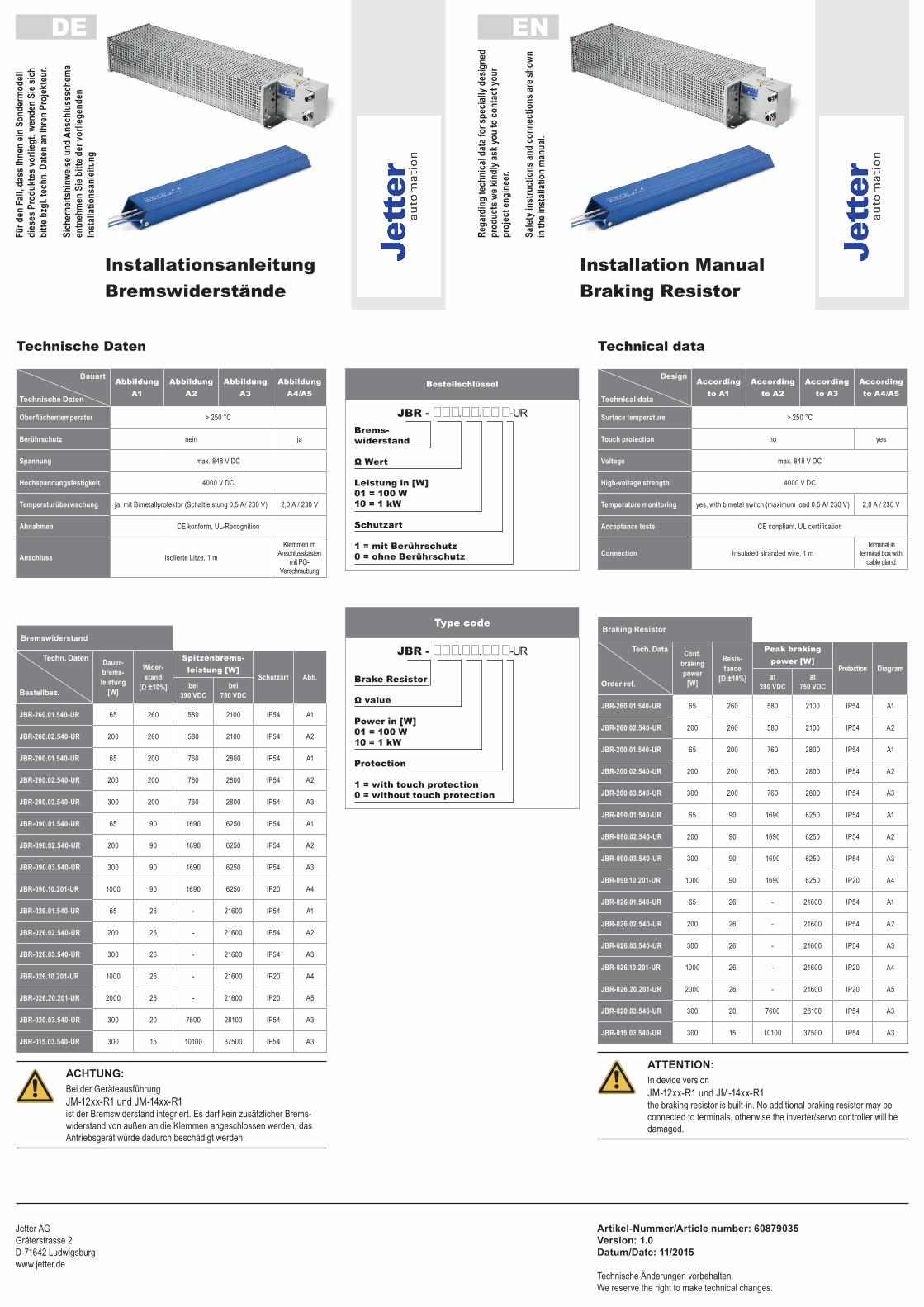
InstallationsanleitungBremswiderstände
Installation ManualBraking Resistor
Bauart
Technische Daten
AbbildungA1
AbbildungA2
AbbildungA3
AbbildungA4/A5
Oberflächentemperatur > 250 °C
Berührschutz nein ja
Spannung max. 848 V DC
Hochspannungsfestigkeit 4000 V DC
Temperaturüberwachung ja, mit Bimetallprotektor (Schaltleistung 0,5 A/ 230 V) 2,0 A / 230 V
Abnahmen CE konform, UL-Recognition
Anschluss Isolierte Litze, 1 mKlemmen im
Anschlusskasten mit PG-
Verschraubung
Bremswiderstand
Techn. Daten
Bestellbez.
Dauer-brems-leistung
[W]
Wider-stand
[Ω ±10%]
Spitzenbrems- leistung [W]
Schutzart Abb.bei
390 VDCbei
750 VDC
JBR-260.01.540-UR 65 260 580 2100 IP54 A1
JBR-260.02.540-UR 200 260 580 2100 IP54 A2
JBR-200.01.540-UR 65 200 760 2800 IP54 A1
JBR-200.02.540-UR 200 200 760 2800 IP54 A2
JBR-200.03.540-UR 300 200 760 2800 IP54 A3
JBR-090.01.540-UR 65 90 1690 6250 IP54 A1
JBR-090.02.540-UR 200 90 1690 6250 IP54 A2
JBR-090.03.540-UR 300 90 1690 6250 IP54 A3
JBR-090.10.201-UR 1000 90 1690 6250 IP20 A4
JBR-026.01.540-UR 65 26 - 21600 IP54 A1
JBR-026.02.540-UR 200 26 - 21600 IP54 A2
JBR-026.03.540-UR 300 26 - 21600 IP54 A3
JBR-026.10.201-UR 1000 26 - 21600 IP20 A4
JBR-026.20.201-UR 2000 26 - 21600 IP20 A5
JBR-020.03.540-UR 300 20 7600 28100 IP54 A3
JBR-015.03.540-UR 300 15 10100 37500 IP54 A3
AchTung:Bei der GeräteausführungJM-12xx-R1 und JM-14xx-R1ist der Bremswiderstand integriert. Es darf kein zusätzlicher Brems-widerstand von außen an die Klemmen angeschlossen werden, das Antriebsgerät würde dadurch beschädigt werden.
Design
Technical data
Accordingto A1
Accordingto A2
Accordingto A3
Accordingto A4/A5
Surface temperature > 250 °C
Touch protection no yes
Voltage max. 848 V DC
High-voltage strength 4000 V DC
Temperature monitoring yes, with bimetal switch (maximum load 0.5 A/ 230 V) 2,0 A / 230 V
Acceptance tests CE conpliant, UL certification
Connection Insulated stranded wire, 1 mTerminal in
terminal box with cable gland
Braking Resistor
Tech. Data
Order ref.
Cont.brakingpower
[W]
Resis-tance
[Ω ±10%]
Peak brakingpower [W]
Protection Diagramat
390 VDCat
750 VDC
JBR-260.01.540-UR 65 260 580 2100 IP54 A1
JBR-260.02.540-UR 200 260 580 2100 IP54 A2
JBR-200.01.540-UR 65 200 760 2800 IP54 A1
JBR-200.02.540-UR 200 200 760 2800 IP54 A2
JBR-200.03.540-UR 300 200 760 2800 IP54 A3
JBR-090.01.540-UR 65 90 1690 6250 IP54 A1
JBR-090.02.540-UR 200 90 1690 6250 IP54 A2
JBR-090.03.540-UR 300 90 1690 6250 IP54 A3
JBR-090.10.201-UR 1000 90 1690 6250 IP20 A4
JBR-026.01.540-UR 65 26 - 21600 IP54 A1
JBR-026.02.540-UR 200 26 - 21600 IP54 A2
JBR-026.03.540-UR 300 26 - 21600 IP54 A3
JBR-026.10.201-UR 1000 26 - 21600 IP20 A4
JBR-026.20.201-UR 2000 26 - 21600 IP20 A5
JBR-020.03.540-UR 300 20 7600 28100 IP54 A3
JBR-015.03.540-UR 300 15 10100 37500 IP54 A3
ATTenTiOn:In device versionJM-12xx-R1 und JM-14xx-R1the braking resistor is built-in. No additional braking resistor may be connected to terminals, otherwise the inverter/servo controller will be damaged.
Technische Daten Technical data
Bestellschlüssel
Type code
JBR - ..-URBrems- widerstand
Ω Wert
Leistung in [W]01 = 100 W10 = 1 kW
Schutzart
1 = mit Berührschutz0 = ohne Berührschutz
JBR - ..-UR
Brake Resistor
Ω value
Power in [W]01 = 100 W10 = 1 kW
Protection
1 = with touch protection0 = without touch protection
Jetter AGGräterstrasse 2 D-71642 Ludwigsburg www.jetter.de
Artikel-nummer/Article number: 60879035 Version: 1.0 Datum/Date: 11/2015
Technische Änderungen vorbehalten.We reserve the right to make technical changes.
Lesen Sie zuerst die Installationsanleitung!• Sicherheitshinweise beachten!
Von elektrischen Antrieben gehen grundsätzlich Gefahren aus: • elektrische Spannungen > 230 V/460 V: Auch 10 min. nach Netz-Aus
können noch gefährlich hohe Spannungen anliegen.
• heiße Oberflächen
Ihre Qualifikation:• Zur Vermeidung von Personen- und Sachschäden darf nur qualifiziertes Personal
mit elektrotechnischer Ausbildung an dem Gerät arbeiten.
• Kenntnis der nationalen Unfallverhütungsvorschriften
Beachten Sie bei der Installation:• Anschlussbedingungen und technische Daten unbedingt einhalten.
• Normen zur elektrischen Installation beachten, z. B. Leitungsquerschnitt, Schutzleiter- und Erdungsanschluss.
1.First read the installation manual!• Follow the safety instructions!
Electric drives present a fundamental safety risk:• Electrical voltages > 230 V/460 V: Dangerously high tension may still be present
even 10 minutes after the power has been cut.
• Hot surfaces
Qualifications:• To avoid personal injury or damage to property, only qualified personnel with training
in electrical engineering may be permitted to work on the device.
• Knowledge of national accident prevention regulations.
During installation:• Always observe connection conditions and technical specifications.
• Comply with electrical installation standards, e.g. conductor cross-section, PE conductor and grounding connections.
1.
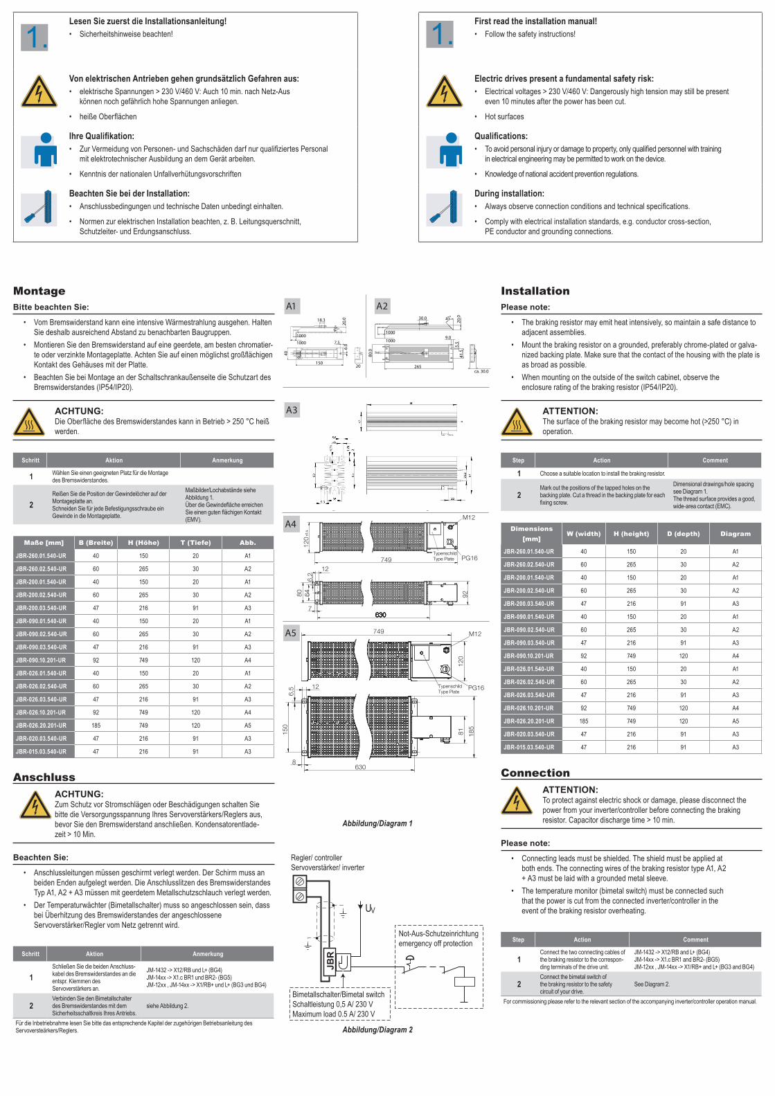
MontageBitte beachten Sie:
• Vom Bremswiderstand kann eine intensive Wärmestrahlung ausgehen. Halten Sie deshalb ausreichend Abstand zu benachbarten Baugruppen.
• Montieren Sie den Bremswiderstand auf eine geerdete, am besten chromatier-te oder verzinkte Montageplatte. Achten Sie auf einen möglichst großflächigen Kontakt des Gehäuses mit der Platte.
• Beachten Sie bei Montage an der Schaltschrankaußenseite die Schutzart des Bremswiderstandes (IP54/IP20).
AchTung:Die Oberfläche des Bremswiderstandes kann in Betrieb > 250 °C heiß werden.
Schritt Aktion Anmerkung
1 Wählen Sie einen geeigneten Platz für die Montage des Bremswiderstandes.
2Reißen Sie die Position der Gewindelöcher auf der Montageplatte an. Schneiden Sie für jede Befestigungsschraube ein Gewinde in die Montageplatte.
Maßbilder/Lochabstände siehe Abbildung 1. Über die Gewindefläche erreichen Sie einen guten flächigen Kontakt (EMV).
Maße [mm] B (Breite) H (Höhe) T (Tiefe) Abb.
JBR-260.01.540-UR 40 150 20 A1
JBR-260.02.540-UR 60 265 30 A2
JBR-200.01.540-UR 40 150 20 A1
JBR-200.02.540-UR 60 265 30 A2
JBR-200.03.540-UR 47 216 91 A3
JBR-090.01.540-UR 40 150 20 A1
JBR-090.02.540-UR 60 265 30 A2
JBR-090.03.540-UR 47 216 91 A3
JBR-090.10.201-UR 92 749 120 A4
JBR-026.01.540-UR 40 150 20 A1
JBR-026.02.540-UR 60 265 30 A2
JBR-026.03.540-UR 47 216 91 A3
JBR-026.10.201-UR 92 749 120 A4
JBR-026.20.201-UR 185 749 120 A5
JBR-020.03.540-UR 47 216 91 A3
JBR-015.03.540-UR 47 216 91 A3
AnschlussAchTung:Zum Schutz vor Stromschlägen oder Beschädigungen schalten Sie bitte die Versorgungsspannung Ihres Servoverstärkers/Reglers aus, bevor Sie den Bremswiderstand anschließen. Kondensatorentlade-zeit > 10 Min.
Beachten Sie:
• Anschlussleitungen müssen geschirmt verlegt werden. Der Schirm muss an beiden Enden aufgelegt werden. Die Anschlusslitzen des Bremswiderstandes Typ A1, A2 + A3 müssen mit geerdetem Metallschutzschlauch verlegt werden.
• Der Temperaturwächter (Bimetallschalter) muss so angeschlossen sein, dass bei Überhitzung des Bremswiderstandes der angeschlossene Servoverstärker/Regler vom Netz getrennt wird.
Schritt Aktion Anmerkung
1Schließen Sie die beiden Anschluss-kabel des Bremswiderstandes an die entspr. Klemmen des Servoverstärkers an.
JM-1432 -> X12/RB und L+ (BG4) JM-14xx -> X1.c BR1 und BR2- (BG5) JM-12xx , JM-14xx -> X1/RB+ und L+ (BG3 und BG4)
2Verbinden Sie den Bimetallschalter des Bremswiderstandes mit dem Sicherheitsschaltkreis Ihres Antriebs.
siehe Abbildung 2.
Für die Inbetriebnahme lesen Sie bitte das entsprechende Kapitel der zugehörigen Betriebsanleitung des Servoversteärkers/Reglers.
InstallationPlease note:
• The braking resistor may emit heat intensively, so maintain a safe distance to adjacent assemblies.
• Mount the braking resistor on a grounded, preferably chrome-plated or galva-nized backing plate. Make sure that the contact of the housing with the plate is as broad as possible.
• When mounting on the outside of the switch cabinet, observe the enclosure rating of the braking resistor (IP54/IP20).
ATTenTiOn:The surface of the braking resistor may become hot (>250 °C) in operation.
Step Action Comment
1 Choose a suitable location to install the braking resistor.
2Mark out the positions of the tapped holes on the backing plate. Cut a thread in the backing plate for each fixing screw.
Dimensional drawings/hole spacing see Diagram 1. The thread surface provides a good, wide-area contact (EMC).
Dimensions [mm]
W (width) H (height) D (depth) Diagram
JBR-260.01.540-UR 40 150 20 A1
JBR-260.02.540-UR 60 265 30 A2
JBR-200.01.540-UR 40 150 20 A1
JBR-200.02.540-UR 60 265 30 A2
JBR-200.03.540-UR 47 216 91 A3
JBR-090.01.540-UR 40 150 20 A1
JBR-090.02.540-UR 60 265 30 A2
JBR-090.03.540-UR 47 216 91 A3
JBR-090.10.201-UR 92 749 120 A4
JBR-026.01.540-UR 40 150 20 A1
JBR-026.02.540-UR 60 265 30 A2
JBR-026.03.540-UR 47 216 91 A3
JBR-026.10.201-UR 92 749 120 A4
JBR-026.20.201-UR 185 749 120 A5
JBR-020.03.540-UR 47 216 91 A3
JBR-015.03.540-UR 47 216 91 A3
ConnectionATTenTiOn:To protect against electric shock or damage, please disconnect the power from your inverter/controller before connecting the braking resistor. Capacitor discharge time > 10 min.
Please note:
• Connecting leads must be shielded. The shield must be applied at both ends. The connecting wires of the braking resistor type A1, A2 + A3 must be laid with a grounded metal sleeve.
• The temperature monitor (bimetal switch) must be connected such that the power is cut from the connected inverter/controller in the event of the braking resistor overheating.
Step Action Comment
1Connect the two connecting cables of the braking resistor to the correspon-ding terminals of the drive unit.
JM-1432 -> X12/RB and L+ (BG4) JM-14xx -> X1.c BR1 and BR2- (BG5) JM-12xx , JM-14xx -> X1/RB+ and L+ (BG3 and BG4)
2Connect the bimetal switch of the braking resistor to the safety circuit of your drive.
See Diagram 2.
For commissioning please refer to the relevant section of the accompanying inverter/controller operation manual.
A118.3
6.01000 7.5
150
45°
1000
40
6
20.0
20
A2
265ca. 30.0
45°
1000
80.0
20.030.0
41.5
5.5
9.01000
A3
5
61.
5
6
310
285320
417
18
115 70
40 6
Ø 10
500
58 32
105
8
107.5 48 6.2
6 90
6 60
6.2
34 6.2
R6
6
60
9
75
80
110 ca.114
11
767 865
640.0
90
A4
A5
58 32
105
8
200 ca. 204
767 865
5107,5 48 640,534
119
6
R 6
6060
6 6,2
6
180
180
6,2
6,2
42
JBR
Not-Aus-Schutzeinrichtungemergency off protection
Bimetallschalter/Bimetal switchSchaltleistung 0,5 A/ 230 V Maximum load 0.5 A/ 230 V
UV
Regler/ controllerServoverstärker/ inverter
Abbildung/Diagram 1
Abbildung/Diagram 2
80
630630
A1
A2
A3
5
61.
5
6
310
285320
417
18
115 70
40 6
Ø 10
500
A4
A5
Temperaturschalter /temperature switch
Temperaturschalter /temperature switch
TypenschildType Plate749
120
630
9280 646,
2
12
7
749
630630630630630
308
320 26
8010
4,5
60
4,5
26
8010
148
160
6015
6308
12
81 185
6,5
150
120
M12
PG16
TypenschildType Plate
M12
PG16