Embed Size (px)
Citation preview

INSTALLATION MANUAL
AIR CONDITIONERINDOOR UNITWall Mounted Type
Contents
1. SAFETY PRECAUTIONS ............................................. 21.1. IMPORTANT! Please read before starting ............. 21.2. SPECIAL PRECAUTIONS ..................................... 2
2. ABOUT THE UNIT ........................................................ 32.1. Precautions for using R410A refrigerant ..................32.2. Special tools for R410A ............................................32.3. For authorized service personnel only. .................. 32.4. Accessories ........................................................... 42.5. Optional parts ...........................................................4
3. GENERAL ..................................................................... 43.1. Type of copper pipe and insulation material .......... 43.2. Additional materials required for installation .......... 43.3. Operating range..................................................... 5
4. ELECTRICAL REQUIREMENT .................................... 55. SELECTING THE MOUNTING POSITION ................... 56. INSTALLATION WORK ................................................ 5
6.1. Installation dimensions .......................................... 56.2. Indoor unit piping direction .................................... 56.3. Cutting the hole in the wall for the connecting piping .... 66.4. Installing the wall hook bracket ............................. 66.5. Forming the drain hose and pipe ........................... 66.6. Flare connection (Pipe connection) ....................... 7
7. ELECTRICAL WIRING ................................................. 87.1. Wiring system diagram .......................................... 87.2. How to the install the indoor unit wire harness ...... 97.3. How to connect wiring to the terminals .................. 9
8. FINISHING .................................................................. 109. FRONT PANEL REMOVAL AND INSTALLATION ..... 10
9.1. Intake grille removal ............................................ 109.2. Intake grille installation ........................................ 109.3. Front panel removal............................................. 109.4. Front panel installation ........................................ 10
10. TEST RUN .................................................................. 1111. REMOTE CONTROLLER INSTALLATION ................ 11
11.1. Remote controller holder installation ................. 11
12. OPTIONAL KIT INSTALLATION(OPTION) ................ 1212.1. Before install optional remote controller ............ 1212.2. Remote controller cable modifi cation ................ 1212.3. External input / output Wire modifi cation........... 1212.4. Front panel, control box cover and display
case removal ..................................................... 1212.5. Connecting cable to control board connector ....... 1312.6. Front panel, control box cover and display
case installation ................................................. 13
13. FUNCTION SETTING ................................................. 1414. ERROR CODES ......................................................... 1615. CUSTOMER GUIDANCE ........................................... 17
PART NO. 9318739022
For authorized service personnel only.
9318739022_IM.indb 19318739022_IM.indb 1 2010-11-2 15:24:332010-11-2 15:24:33

En-2
1. SAFETY PRECAUTIONS1
1.1. IMPORTANT! Please read before starting
This air conditioning system meets strict safety and operating standards.As the installer or service person, it is an important part of your job to install or service the system so it operates safely and effi ciently.
For safe installation and trouble-free operation, you must:• Carefully read this instruction booklet before beginning.• Follow each installation or repair step exactly as shown.• Observe all local, state, and national electrical codes.• Pay close attention to all danger, warning, and caution
notices given in this manual.
WARNING: This symbol refers to a hazard or unsafe practice which can result in severe personal injury or death.
CAUTION: This symbol refers to a hazard or unsafe practice which can result in personal injury and the potential for product or property damage.
• Hazard alerting symbols
Electrical
Safety/alert
If Necessary, Get HelpThese instructions are all you need for most installation sites and maintenance conditions. If you require help for a special problem, contact our sales/service outlet or your certified dealer for additional instructions.
In Case of Improper InstallationThe manufacturer shall in no way be responsible for improper installation or maintenance service, including failure to follow the instructions in this document.
1.2. SPECIAL PRECAUTIONS
When WiringELECTRICAL SHOCK CAN CAUSE SEVERE PERSONAL INJURY OR DEATH. ONLY A QUALIFIED, EXPERIENCED ELECTRICIAN SHOULD ATTEMPT TO WIRE THIS SYSTEM.• Do not supply power to the unit until all wiring and tubing
are completed or reconnected and checked.• Highly dangerous electrical voltages are used in this sys-
tem. Carefully refer to the wiring diagram and these instruc-tions when wiring. Improper connections and inadequate grounding can cause accidental injury or death.
• Ground the unit following local electrical codes.• Connect all wiring tightly. Loose wiring may cause overheat-
ing at connection points and a possible fi re hazard.
When TransportingBe careful when picking up and moving the indoor and outdoor units. Get a partner to help, and bend your knees when lifting to reduce strain on your back. Sharp edges or thin aluminum fi ns on the air conditioner can cut your fi ngers.
When Installing......In a Ceiling or WallMake sure the ceiling/wall is strong enough to hold the unit’s weight. It may be necessary to construct a strong wood or metal frame to provide added support.
...In a RoomProperly insulate any tubing run inside a room to prevent “sweating” that can cause dripping and water damage to walls and fl oors.
...In Moist or Uneven LocationsUse a raised concrete pad or concrete blocks to provide a solid, level foundation for the outdoor unit. This prevents water damage and abnormal vibration.
...In an Area with High WindsSecurely anchor the outdoor unit down with bolts and a metal frame. Provide a suitable air baffl e.
...In a Snowy Area (for Heat Pump-type Systems)Install the outdoor unit on a raised platform that is higher than drifting snow.
When Connecting Refrigerant Tubing• Keep all tubing runs as short as possible.• Use the fl are method for connecting tubing.• Apply refrigerant lubricant to the matching surfaces of the fl are and union tubes before connecting them, then tighten the nut with a torque wrench for a leak-free connection.
• Check carefully for leaks before opening the refrigerant valves.
When Servicing• Turn the power OFF at the main circuit breaker panel
before opening the unit to check or repair electrical parts and wiring.
• Keep your fingers and clothing away from any moving parts.
• Clean up the site after you finish, remembering to check that no metal scraps or bits of wiring have been left inside the unit being serviced.
• After installation, explain correct operation to the customer, using the operating manual.
DANGERNever touch electrical components immediately af-ter the power supply has been turned off. Electrical shock may occur. After turning off the power, always wait 5 minutes or more before touching electrical components.
9318739022_IM.indb Sec1:29318739022_IM.indb Sec1:2 2010-11-2 15:24:372010-11-2 15:24:37
En-3
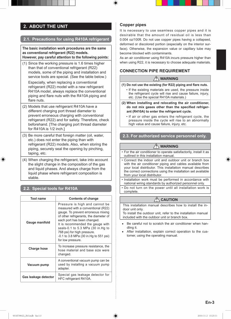
2. ABOUT THE UNIT1
2.1. Precautions for using R410A refrigerant
The basic installation work procedures are the same as conventional refrigerant (R22) models.However, pay careful attention to the following points:(1) Since the working pressure is 1.6 times higher
than that of conventional refrigerant (R22) models, some of the piping and installation and service tools are special. (See the table below.)
Especially, when replacing a conventional refrigerant (R22) model with a new refrigerant R410A model, always replace the conventional piping and fl are nuts with the R410A piping and fl are nuts.
(2) Models that use refrigerant R410A have a different charging port thread diameter to prevent erroneous charging with conventional refrigerant (R22) and for safety. Therefore, check beforehand. [The charging port thread diameter for R410A is 1/2 inch.]
(3) Be more careful that foreign matter (oil, water, etc.) does not enter the piping than with refrigerant (R22) models. Also, when storing the piping, securely seal the opening by pinching, taping, etc.
(4) When charging the refrigerant, take into account the slight change in the composition of the gas and liquid phases. And always charge from the liquid phase where refrigerant composition is stable.
1
2.2. Special tools for R410A
Tool name Contents of change
Gauge manifold
Pressure is high and cannot be measured with a conventional (R22) gauge. To prevent erroneous mixing of other refrigerants, the diameter of each port has been changed.It is recommended the gauge with seals-0.1 to 5.3 MPa (30 in.Hg to 768 psi) for high pressure.-0.1 to 3.8 MPa (30 in.Hg to 551 psi) for low pressure.
Charge hose To increase pressure resistance, the hose material and base size were changed.
Vacuum pumpA conventional vacuum pump can be used by installing a vacuum pump adapter.
Gas leakage detector Special gas leakage detector for HFC refrigerant R410A.
Copper pipesIt is necessary to use seamless copper pipes and it is desirable that the amount of residual oi l is less than 0.004 oz/100ft. Do not use copper pipes having a collapsed, deformed or discolored portion (especially on the interior sur-face). Otherwise, the expansion value or capillary tube may become blocked with contaminants.As an air conditioner using R410A incurs pressure higher than when using R22, it is necessary to choose adequate materials.
CONNECTION PIPE REQUIREMENT
WARNING(1) Do not use the existing (for R22) piping and fl are nuts.
• If the existing materials are used, the pressure inside the refrigerant cycle will rise and cause failure, injury, etc. (Use the special R410A materials.)
(2) When installing and relocating the air conditioner, do not mix gases other than the specifi ed refriger-ant (R410A) to enter the refrigerant cycle.• If air or other gas enters the refrigerant cycle, the
pressure inside the cycle will rise to an abnormally high value and cause failure, injury, etc.
2.3. For authorized service personnel only.
WARNING• For the air conditioner to operate satisfactorily, install it as
outlined in this installation manual.• Connect the indoor unit and outdoor unit or branch box
with the air conditioner piping and cables available from your local distributor. This installation manual describes the correct connections using the installation set available from your local distributor.
• Installation work must be performed in accordance with national wiring standards by authorized personnel only.
• Do not turn on the power until all installation work is complete.
CAUTIONThis installation manual describes how to install the in-door unit only.To install the outdoor unit, refer to the installation manual included with the outdoor unit or branch box.
• Be careful not to scratch the air conditioner when han-dling it.
• After installation, explain correct operation to the cus-tomer, using the operating manual.
9318739022_IM.indb Sec1:39318739022_IM.indb Sec1:3 2010-11-2 15:25:112010-11-2 15:25:11

En-4
2.4. AccessoriesThe following installation accessories are supplied. Use them as required.
Name and Shape Q’ty Name and Shape Q’tyOperating Manual
1
Drain hose insulation
1
Installation Manual(This manual)
1
Cloth tape
1
Wall hook bracket
1
Tapping screw (big)
8
Remote controller
1
Tapping screw (small)
2
Battery
2
Air cleaning filter
2
Remote controller holder 1
Air cleaning filter frame
2
The following items are necessary to install this air condi-tioner. (The items are not included with the air conditioner and must be purchased separately.)
Name Q’tyConnection pipe assembly 1Connection cable (4-conductor) 1Wall pipe 1Decorative tape 1Vinyl tape 1Wall cap 1Saddle 1 setDrain hose 1Tapping screws 1 setSealant 1M10 bolt, nut 4 set
1
2.5. Optional parts
3. GENERALThis INSTALLATION MANUAL briefly outlines where and how to install the air conditioning system. Please read over the entire set of instructions for the indoor and outdoor units and make sure all ac-cessory parts listed are with the system before beginning. ]1
3.1. Type of copper pipe and insulation material
CAUTIONRefer to the installation manual for the outdoor unit for description of allowable pipe length and height difference.
3.1.1. SINGLE TYPE INSTALLATION
MODELDiameter
Liquid pipe Gas pipe18,000BTU/h model 9.52mm (3/8in.)* 15.88mm (5/8in.)*24,000BTU/h model 9.52mm (3/8in.)* 15.88mm (5/8in.)
* When single type installation, the ADAPTER included outdoor unit is necessary to connect the indoor unit to the outdoor unit.
3.1.2. MULTI TYPE INSTALLATION
MODELDiameter
Liquid pipe Gas pipe18,000BTU/h model 6.35mm (1/4in.) 12.70mm (1/2in.)24,000BTU/h model 6.35mm (1/4in.) 15.88mm (5/8in.)
CAUTIONInstall heat insulation around both the gas and liquid pipes.Failure to do so may cause water leaks.Use heat insulation with heat resistance above 248 °F. Reverse cycle model onlyIn addition, if the humidity level at the installation location of the refrigerant piping is expected to exceed 70%, install heat insulation around the refrigerant piping. If the expected humidity level is 70-80%, use heat insulation that is 15 mm (19/32 in.) or thicker and if the expected humidity exceeds 80%, use heat insulation that is 20 mm (25/32 in.) or thicker.If heat insulation is used that is not as thick as specifi ed, condensation may form on the surface of the insulation. In addition, use heat insulation with heat conductivity of 0.045 W/(m•K) or less (at 68 °F).
]1
3.2. Additional materials required for installationA. Refrigeration (armored) tapeB. Insu lated s tap les or c lamps for connect ing wi re
(See your local electrical codes.)C. PuttyD. Refrigeration lubricantE. Clamps or saddles to secure refrigerant piping
Model No.Parts name Application
Wired Remote Controller
UTY-RNNUM
For air conditioner operation
Wireless Remote Controller
UTY-LNHUM
For air conditioner operation
For air conditioner operation
Simple Remote Controller
UTY-RSNUM
For control input/output port
External connect kit
UTY-XWZX
Refer to each installation manual for the method of installing optional parts.
9318739022_IM.indb Sec1:49318739022_IM.indb Sec1:4 2010-11-2 15:25:112010-11-2 15:25:11

En-5
]1
3.3. Operating range
Cooling/ Dry Mode Heating ModeTemperature About 64 to 90 °F About 60 to 88 °F
Humidity About 80% or less ─
4. ELECTRICAL REQUIREMENTThe indoor unit is powered from the outdoor unit or branch box. Do not power indoor unit from separate power source.
WARNINGRefer to local codes for acceptable cable type.
Cable Cable size RemarksConnection cable 14AWG 3 cable + Ground, 1 Ø 208/230V
Max. Cable Length: Limit voltage drop to less than 2%. Increase cable gauge if voltage drop is 2% or more.
5. SELECTING THE MOUNTING POSITIONDecide the mounting position with the customer as follows:(1) Install the indoor unit level on a strong wall which is not
subject to vibration.(2) The inlet and outlet ports should not be obstructed : the air
should be able to blow all over the room.(3) Install the unit a dedicated electrical branch circuit.(4) Do not install the unit where it will be exposed to direct sunlight.(5) Install the unit where connection to the outdoor unit or
branch box is easy.(6) Install the unit where the drain pipe can be easily installed.(7) Take servicing, etc. into consideration and leave the
spaces shown in [6.1. Installation dimensions]. Also install the unit where the filter can be removed.
Correct initial installation location is important because it is diffi cult to move unit after it is installed.
WARNING• Select installation locations that can properly support the
weight of the indoor. Install the units securely so that they do not topple or fall.
CAUTION• Do not install the unit in the following areas:
• Area with high salt content, such as at the seaside.It will deteriorate metal parts, causing the parts to fail or the unit to leak water.
• Area fi lled with mineral oil or containing a large amount of splashed oil or steam, such as a kitchen.It will deteriorate plastic parts, causing the parts to fail or the unit to leak water.
• Area that generates substances that adversely affect the equipment, such as sulfuric gas, chlorine gas, acid, or alkali.It will cause the copper pipes and brazed joints to corrode, which can cause refrigerant leakage.
• Area that can cause combustible gas to leak, contains suspended carbon fi bers or fl ammable dust, or volatile infl ammables such as paint thinner or gasoline.If gas leaks and settles around the unit, it can cause a fi re.
• Area where animals may urinate on the unit or ammonia may be generated.
• Do not use the unit for special purposes, such as storing food, raising animals, growing plants, or preserving precision devices or art objects.It can degrade the quality of the preserved or stored objects.
• Do not install where there is the danger of combustible gas leakage.
• Do not install the unit near a source of heat, steam, or fl ammable gas.
• Install the unit where drainage does not cause any trouble.
• Install the indoor unit, outdoor unit, branch box , power supply cable, transmission cable, and remote controller cable at least 40 in. (1 m) away from a television or radio receivers. The purpose of this is to prevent TV reception interference or radio noise. (Even if they are installed more than 40 in. (1 m) apart, you could still receive noise under some signal conditions.)
• If children under 10 years old may approach the unit, take preventive measures so that they cannot reach the unit.
• Install the indoor unit on the wall where the height from the fl oors more than 1800 mm (70 in.).
6. INSTALLATION WORK]1
6.1. Installation dimensions
Remote controller Remote controller holder
Tapping screw (small)
(Wall cap)
1500 mm (59-1/16 in.) or over
80 mm (3-5/32 in.) or over
80 mm (3-5/32 in.) or over
Wall hook bracket
120 mm (4-23/32 in.) or over
1800 mm (70 in.) or over
*
**
* Space from wall hook bracket .]1
6.2. Indoor unit piping direction
The piping can be connected in the 7 directions in the fi gure. When the piping is connected in direction 2, 3, 4 or 5, cut along the piping groove in the side of the front panel with a hacksaw.
1 Rear outlet
2 Right outlet
3 Bottom outlet
4 Left bottom outlet
5 Left outlet
(Rear)
6 Center outlet
7 Left rear outlet
9318739022_IM.indb Sec1:59318739022_IM.indb Sec1:5 2010-11-2 15:25:122010-11-2 15:25:12

En-6
6.3. Cutting the hole in the wall for the connecting piping(1) Cut a 80 mm (3-5/32 in.) diameter hole in the wall at the
position shown in the fi gure.(2) When cutting the wall hole at the inside of the wall hook
bracket, cut the hole to a point of intersection of center marks. When cutting the wall hole at the outside of the wall hook
bracket, cut the hole at a point of 10 mm (13/32 in.) below.(3) Cut the hole so that the outside end is lower (5 to 10 mm
(3/16 to 13/32 in.)) than the inside end.(4) Always align the center of the wall hole. If misaligned, wa-
ter leakage will occur.(5) Cut the wall pipe to match the wall thickness, stick it into
the wall cap, fasten the cap with vinyl tape, and stick the pipe through the hole.
(6) For left piping and right piping, cut the hole a little lower so that drain water will fl ow freely.
80 mm (3-5/32 in.) hole
Centering marksWall hook bracket
10 mm (13/32 in.)or more lower
10 mm (13/32 in.)or more lower
Fasten with vinyl tape
Wall cap*Wall pipe*
(Inside) Wall (Outside)*Field supplied
5 to 10 mm (3/16 to 13/32 in.)
WARNINGIf the wall pipe is not used, the cable interconnecting the indoor unit(s) and outdoor unit or branch box may touch metal and cause electric discharge.
]1
6.4. Installing the wall hook bracket(1) Install the wall hook bracket so that it is correctly posi-
tioned horizontally and vertically. If the wall hook bracket is tiled, water will drip to the fl oor.
(2) Install the wall hook bracket so that it is strong enough to support the weight of the unit.
● Fasten the wall hook bracket to the wall with 6 or more screws through the holes near the outer edge of the bracket.
● Check that there is no rattle at the wall hook bracket.
Wall hook bracket Tapping screw (size: large; quantity: 8)
CAUTIONInstall the wall hook bracket level, both horizontally and vertically.
6.5. Forming the drain hose and pipe
[Rear piping, Right piping, Bottom piping]• Install the indoor unit piping in the direction of the wall hole
and bind the drain hose and pipe together with vinyl tape. • Install the piping so that the drain hose is at the bottom.• Wrap the pipes of the indoor unit that are visible from the
outside with decorative tape.[For Left rear piping, Left piping]Interchange the drain cap and the drain hose.
CAUTION• Insert drain hose and drain cap securely. Drain
should slope down to avoid water leakage.• When inserting, be sure not to attach any material
besides water. If any other material is attached, it will cause deterioration and water leakage.
• After removing drain hose, be sure not to forget mounting drain cap.
• Be sure to fi x the drain hose with tape to the bottom of piping.• Prevent drain water freezing under low temperature
environment.When installing indoor unit’s drain hose outdoors, neces-sary measure for frost protection should be taken to pre-vent drain water freezing. Under low temperature environment (when outdoor tem-perature under 32 °F), after cooling operation is executed, water in the drain hose could be frozen. Once drain water is frozen, the drain hose will be blocked and water leakage may result at the indoor unit.
Right pipingBind with vinyl tape
Indoor unit drain hose (bottom)
Pipe (top)Rear piping
Bottom piping
Drain capIndoor unit drain hose
Remove the drain cap by pulling at the projection at the end of the cap with pliers, etc.
For left outlet piping, cut off the piping outlet cutting groove with a hacksaw.
CAUTION
Insert the drain hose and drain cap into the drain port, making sure that it comes in contact with the back of the drain port, and then mount it. If the drain hose is not connected properly, leaking will occur.
• Attach the Drain hose insulation to the drain hose.
Drain hose insulation
Drain hose
9318739022_IM.indb Sec1:69318739022_IM.indb Sec1:6 2010-11-2 15:25:132010-11-2 15:25:13

En-7
• For left piping and left rear piping, align the marks on the wall hook bracket and shape the connection pipe.
• Bend the connection piping at the bend radius of 100 mm (3-30/32 in.) or more and install no more than 35 mm (1-3/8 in.) from the wall.
• After passing the indoor piping and drain hose through the wall hole, hang the indoor unit on the hooks at the top and bottom of the wall hook bracket.
[Installing the indoor unit]• Hang the indoor unit from the hooks at the top of the wall
hook bracket.• Insert the spacer, etc. between the indoor unit and the wall
hook bracket and separate the bottom of the indoor unit from the wall.
Indoor unit
Wall hook bracket
(Spacer)
Wall hook bracket
Alignment marks
Connection piping Large piping
Top hooks
Indoor unit
(Fitting) Bottom hooks
Wall hook bracket
Small piping
After hooking the indoor unit to the top hook, hook the fi ttings of the indoor unit to the 2 bottom hooks while lowering the unit and pushing it against the wall.
6.6. Flare connection (Pipe connection)
WARNING• Tighten the flare nuts with a torque wrench using the
specifi ed tightening method. Otherwise, the fl are nuts could break after a prolonged period, causing refrigerant to leak and generate hazardous gas if the refrigerant comes into contact with a fl ame.
6.6.1. Flaring• Use special pipe cutter and fl are tool exclusive for R410A.(1) Cut the connection pipe to the necessary length with a pipe cutter.(2) Hold the pipe downward so that cuttings will not enter the
pipe and remove any burrs.(3) Insert the fl are nut (always use the fl are nut attached to the
indoor unit(s) and outdoor unit or branch box respectively) onto the pipe and perform the fl are processing with a fl are tool. Use the special R410A fl are tool, or the conventional flare tool. Leakage of refrigerant may result if other flare nuts are used.
(4) Protect the pipes by pinching them or with tape to prevent dust, dirt, or water from entering the pipes.
Pipe
Check if [L] is flared uniformly and is not cracked or scratched.
Die
L
Pipe outside diameter [mm (in.)]
Dimension A [mm (in.)] Dimension B-
00.4
[mm (in.)]Flare tool for R410A, clutch type
6.35 (1/4)
0 to 0.5 (0 to 0.020)
9.1 (11/32)9.52 (3/8) 13.2 (17/32)
12.70 (1/2) 16.6 (21/32)15.88 (5/8) 19.7 (25/32)19.05 (3/4) 24.0 (15/16)
When using conventional fl are tools to fl are R410A pipes, the dimension A should be approximately 0.5mm (0.020 in.) more than indicated in the table (for fl aring with R410A fl are tools) to achieve the specifi ed fl aring. Use a thickness gauge to measure the dimension A.
Width across flatsflats
Pipe outsidediameter [mm (in.)]
Width across flatsof Flare nut [mm (in.)]
6.35 (1/4) 17 (21/32)9.52 (3/8) 22 (7/8)
12.70 (1/2) 26 (1-1/32)15.88 (5/8) 29 (1-5/32)19.05 (3/4) 36 (1-13/32)
6.6.2. Bending pipes• If pipes are shaped by hand, be careful not to collapse
them.• Do not bend the pipes in an angle more than 90°.• When pipes are repeatedly bend or stretched, the material
will harden, making it diffi cult to bend or stretch them any more.
• Do not bend or stretch the pipes more than 3 times.
CAUTION• To prevent breaking of the pipe, avoid sharp bends.
• If the pipe is bent repeatedly at the same place, it will break.
6.6.3. Pipe connection
CAUTION• Be sure to Install the pipe against the port on the indoor unit
correctly. If the centering is improper, the flare nut cannot tighten smoothly. If the fl are nut is forced to turn, the threads will be damaged.
• Do not remove the fl are nut from the indoor unit pipe until immediately before connecting the connection pipe.
• Hold the torque wrench at its grip, keeping it at a right angle with the pipe, in order to tighten the fl are nut correctly.
• Tighten the flare nuts with a torque wrench using the specifi ed tightening method. Otherwise, the fl are nuts could break after a prolonged period, causing refrigerant to leak and generate hazardous gas if the refrigerant comes into contact with a fl ame.
9318739022_IM.indb Sec1:79318739022_IM.indb Sec1:7 2010-11-2 15:25:142010-11-2 15:25:14

En-8
7. ELECTRICAL WIRING]1
7.1. Wiring system diagramINDOOR UNIT SIDE
INDOOR UNIT
TERMINAL
DISCONNECT SWITCH (FIELD SUPPLY)
208/230 V208/230 V208/230 V
Grounding line
14AWG (Inter-unit) Power lines
OUTDOOR UNIT or BRANCH BOX
Please connect it to the specifi ed terminal.
Disconnect switch - fi eld supplied if required by local code. Select the correct capacity of disconnect switch according to the load.
• To connect the indoor unit wires to the terminal correctly, refer to the fi gure for proper length.
14AWG
Earth wire
175 mm (6-7/8 in.)
190 mm (7-15/32 in.)
25 mm (31/32 in.) 25 mm
(31/32 in.)
Conduit holder
Conduit connector
CAUTIONEvery wire must be connected fi rmly.No wire should be allowed to touch refrigerant tubing, the compressor or any moving part.Loose wiring may cause the terminal to overheat or result in unit malfunction. A fi re hazard may also exist. Therefore, be sure all wiring is tightly connected.Connect wires to the matching numbers of terminals.
CAUTION
• Connect the piping so that the control box cover can easily be removed for servicing when necessary.
• In order to prevent water from leaking into the control box, make sure that the piping is well insulated.
• When single type installation, the ADAPTER included out-door unit is necessary to connect the indoor unit to the out-door unit.
SINGLE TYPE INSTALLATION
MODELADAPTER
Liquid pipe Gas pipe18,000BTU/h model Use Use24,000BTU/h model Use No use
MULTI TYPE INSTALLATION
MODELADAPTER
Liquid pipe Gas pipe18,000BTU/h model No use No use24,000BTU/h model No use No use
When the fl are nut is tightened properly by your hand, hold the body side coupling with a wrench, then tighten with a torque wrench. (See the table below for the fl are nut tightening torques and adapter tightening torque.)
Torque wrench
Connection pipe
Flare nut
Holding wrench
Tighten with two wrenches.
Indoor unit pipe (Body side)
Flare nut tightening torque
Flare nut [mm (in.)] Tightening torque [N·m (lbf·ft)]6.35 (1/4) dia. 16 to 18 (11.8 to 13.3)9.52 (3/8) dia. 32 to 42 (23.6 to 31.0)
12.70 (1/2) dia. 49 to 61 (36.1 to 45.0)15.88 (5/8) dia. 63 to 75 (46.5 to 55.3)19.05 (3/4) dia. 90 to 110 (66.4 to 81.1)
Adapter tightening torqueAdapter type Tightening torque [N·m (lbf·ft.)]
φ6.35mm (1/4in.)→φ9.52mm (3/8in.) 16 to 18 (11.8 to 13.3)
φ12.7mm(1/2in.)→φ15.88mm(5/8in.) 49 to 61 (36.1 to 45.0)
* When using the ADAPTER, be careful not to overtighten the nut, or the smaller pipe may be damaged.
Adapter
Indoor unit pipe
Connection pipeFlare nut
Earth screw
Disconnect switch
Indoor unit terminal block
Outdoor unit or Branch box
Please connect it to the specifi ed terminal.
9318739022_IM.indb Sec1:89318739022_IM.indb Sec1:8 2010-11-2 15:25:152010-11-2 15:25:15

En-9
]1
7.2. How to the install the indoor unit wire harness1. Remove the screws, then remove the conduit holder.2. Fasten the indoor unit wire harness to the conduit holder
using the lock nut.IMPORTANT: Refer to fi gure of indoor unit wire length about the length of indoor unit wire harness.
3. Use the screws to install the conduit holder provide with the indoor unit.
4. Remove the screws, then remove the cable clamp.5. Connect indoor unit wire harness to the terminal.
Refer to the wiring diagram.6. Use the screws to install the cable clamp.
]1
7.3. How to connect wiring to the terminalsCaution when wiring cable
• When stripping off the insulation of a lead wire, always use a special tool such as a wire stripper. If there is no special tool available, carefully strip the insulation with a knife etc.
(1) Use crimp-type terminals with insulating sleeves as shown in the fi gure below to connect to the terminal block.
(2) Securely clamp the crimp-type terminals to the wires using an appropriate tool so that the wires do not come loose.
(3) Use the specifi ed wires, connect them securely, and fasten them so that there is no stress placed on the terminals.
(4) Use an appropriate screwdriver to tighten the terminal screws. Do not use a screwdriver that is too small, other-wise, the screw heads may be damaged and prevent the screws from being properly tightened.
(5) Do not tighten the terminal screws too much, otherwise, the screws may break.
(6) See the table below for the terminal screw tightening torques.
Tightening torque [N·m (lbf·in)]M4 screw 1.2 to 1.8 (11 to 16)
CAUTION• Match the terminal block numbers and connection cable
colors with those of the outdoor unit or branch box. Erroneous wiring may cause burning of the electric parts.
• Connect the connection cables firmly to the terminal block. Imperfect installation may cause a fi re.
• Always fasten the outside covering of the connection cable with the cable clamp. (If the insulator is chafed, electric discharge may occur.)
• Always connect the ground wire.
• Do not use the ground screw of the indoor unit for the connection other than a specifi ed outdoor unit or branch box.
lock nutCONDUIT HOLDER
SCREW CONDUIT CONNECTOR
Connection cableScrew
Cable clamp
Connection cable
Cable clamp
Screw Square hole
Insert the tab into the square hole of the indoor unit and fas-ten with a screw.
Tab
Strip : 10 mm (13/32 in.)
Screw with special washer Screw with special washer
Crimp-type terminal
Terminal blocks
Crimp-type terminal
Wire
Wire
Sleeve
Crimp-type terminal
9318739022_IM.indb Sec1:99318739022_IM.indb Sec1:9 2010-11-2 15:25:162010-11-2 15:25:16

En-10
]1]1
8. FINISHING(1) Insulate between pipes.● Insulate suction and discharge pipes separately.● For rear, right, and bottom piping, overlap the connection
pipe heat insulation and indoor unit pipe heat insulation and bind them with vinyl tape so that there is no gap.
● For left and left rear piping, butt the connection pipe heat insulation and indoor unit pipe heat insulation together and bind them with and vinyl tape so that there is no gap.
● For left and left rear piping, wrap the area which accommodates the rear piping housing section with cloth tape.
● For left and left rear piping, bind the connection cable to the top of the pipe with vinyl tape.
● For left and left rear piping, bundle the piping and drain hose together by wrapping them with cloth tape over the range within which they fi t into the rear piping housing section.
(2) Temporarily fasten the connection cable along the connection pipe with vinyl tape. (Wrap to about 1/3 the width of the tape from the bottom of the pipe so that water does not enter.)
(3) Fasten the connection pipe to the outside wall with saddles, etc.
(4) Fill the gap between the outside wall pipe hole and the pipe with sealer so that rain water and wind cannot blow in.
(5) Fasten the drain hose to the outside wall, etc.
Pipe
Saddle*Outside wall cap*
Sealer putty*
(Outdoors)
*Field suppliedWall
Overlap the insulation
Bind the pipes together so that there is no gap.
Connection pipe (heat insulation)
Vinyl tape
Indoor unit pipe(heat insulation)
Wrap with cloth tape
Pipe
Drain hose Cloth tape
Left pipingConnection cable
Pipe Drain hose
For connection from the left rearConnection cableWall pipe
Connection pipe
Drain hose
Check the following:
GOOD
Lifted up
Saddle
Wave End in water
NO GOOD NO GOOD NO GOOD
Drain hose
]1
9. FRONT PANEL REMOVAL AND INSTALLATION
9.1. Intake grille removal(1) Open the intake grille.(2) Pull down the knob.(3) Lift the intake grille upward, until the axle at the top of the
intake grille is removed.1
9.2. Intake grille installation(1) The fi xing axle of the intake grille is installed on the Panel.(2) Lay down the intake grille.
1
9.3. Front panel removal
(1) Remove intake grille (Reference the intake grille removal.)(2) Remove 6 screws.(3) The thumb is hung on the lower part as shown in the fi gure,
and it pulls to the front, pushing [▲] mark , and bottom hooks (2 position) is removed from wall hook bracket.
(4) The front panel is pulled to the front, raising the upper surface, and a front panel is removed.
9.4. Front panel installation
(1) First, fi t the lower part of the front panel, and insert top and bottom hooks. (3 top sides)
(2) Attach the 6 screws.(3) Attach the intake grille.
Top holes (two sides)
Top hole (center)Top hook (center)
Front panel
Indoor unit Top hooks(2 sides)
Wall hook bracket
Front panel
Push[▲] mark
Screws (6 position)
Push
Front panel
Front panelBearingMounting shaft
Intake grille Intake grille
Knob
CAUTIONInstall the front panel and INTAKE GRILLE securely. If installation is imperfect, the front panel or INTAKE GRILLE may fall off and cause injury.
9318739022_IM.indb Sec1:109318739022_IM.indb Sec1:10 2010-11-2 15:25:162010-11-2 15:25:16

En-11
10. TEST RUN
WARNINGDo not turn on the power until all installation work is complete.
CAUTIONWhen restarting after a long period of disuse in the winter, turn the power switch on at least 12 hours before starting the unit.
Check items(1) Is operation of each button on the remote controller nor-
mal?(2) Does each lamp light normally?(3) Do air fl ow direction louvers operate normally?(4) Is the drain normal?(5) Do not have an abnormal noise and vibration during op-
eration?● Do not operate the air conditioner in test run for a long
time.
[Operation method]● For the operation method, refer to the operating manual.● The outdoor unit may not operate depending on the room
temperature.In this case, press the test run button on the remote controller while the air conditioner is running. (Point the transmitter section of the remote controller toward the air conditioner and press the test run button with the tip of a ballpoint pen, etc.)
● To end test operation, press the remote controller START/STOP button.(When the air conditioner is running by pressing the test run button, the OPERATION Lamp and TIMER Lamp will simultaneously fl ash slowly.)
[Using the wired remote controller] (Option)● For the operation method, refer to the operating manual.
(1) Stop the air conditioner operation.(2) Press the master control button and the fan control button
simultaneously for 2 seconds or more to start the test run.
(3) Press the start/stop button to stop the test run.
Transmitter section
Test run button
Test run display
11. REMOTE CONTROLLER INSTALLATION1
CAUTION
• Check that the indoor unit correctly receives the signal from the remote controller, then install the remote controller holder.
• Select the remote controller holder selection site by paying careful attention to the following:
Avoid places in direct sunlight. Select a place that will not be affected by the heat
from a stove, etc.
11.1. Remote controller holder installation
• Install the remote controller a maximum distance of 7 m (23 ft) from the remote control receiver. However, when installing the remote controller, check that it operates cor-rectly.
• Install the remote controller holder to a wall, pillar, etc. with the tapping screw.
Remote controller holder fixing Remote controller mounting
Remote controller holder
Tapping screw (small) Remote
controller
(2) Push
(1) Set
9318739022_IM.indb Sec1:119318739022_IM.indb Sec1:11 2010-11-2 15:25:182010-11-2 15:25:18

En-12
12.3. External input / output Wire modifi cation
(1) Remove insulation from wire attached to wire kit connector. Remove insulation from field supplied cable. Use crimp type insulated butt connector to join fi eld cable and wire kit wire.
(2) Connect the wire and Field supply wire. (supplied with external connect kit)
Important: Be sure to solder wires to connect. Be sure to insulate the connection between the wires.
Option partsExternal input/output wire
Insulated connection
Cable (Field supply)
]1
12.4. Front panel, control box cover and display case removal
(1) Refer to “FRONT PANEL REMOVAL AND INSTALLATION” to remove the front panel.
(2) Remove the screw then remove the control box cover.(3) Remove the display case and connector.
control box cover
screw
display case
connector
12. OPTIONAL KIT INSTALLATION(OPTION)This air conditioner can be connected with the following op-tional kits. Refer to each installation manual for the method of installing optional parts.• Wired remote controller• Simple remote controller• External connect kit
]1
12.1. Before install optional remote controller• When you use optional remote controller, some functions
may not be used.• Please use the recommended optional remote controller.
CAUTION• Before installing, be sure to disconnect all power supply.
• Don’t touch the heat exchanger.
• During installing or removing operation, be sure not to have wire caught by parts or pull it hard.
• Avoid place in direct sunlight.
• Select placing that will not be affected by the heat from a stove, etc.
• Before setting up the optional kit, please confirm whether air-conditioner can receive the signal.
• Do not connect the optional remote controller to the terminal for power supply.
• When connecting the optional remote controller with the indoor unit, please use the connecting cable packaged up with the optional remote controller.
• Recommended cable length of optional remote controller is 10 m (33 ft). Make sure to do insulate of connecting part when extending the cable.
]1
12.2. Remote controller cable modifi cation
(1) Use a tool to cut off the terminal on the end of the remote controller cable,and then remove the insulation from the cut end of the cable.
(2) Connect the remote controller cable and connecting cable. (supplied with wired remote controller)
Important: Be sure to solder wires to connect. Be sure to insulate the connection between the wires.
Connecting cable
WhiteRed
WhiteRed
Black
Black
InsulatedconnectionRemote
controller cable
Remotecontroller cable
20 m
m
(13/
16 in
.)
9318739022_IM.indb Sec1:129318739022_IM.indb Sec1:12 2010-11-2 15:25:182010-11-2 15:25:18

En-13
]1
12.5. Connecting cable to control board connector
(1) Pass the cable from the hole in the back of indoor unit.(2) Connect the cable to the control board connector.(3) Hook the cable to the rib.
Option type Connector NoWired remote controller
Simple remote contoroller CN6
External input CN14External output CN16
(4) Use cable clamper and screw to fasten the cable of wired remote controller.
(5) Fix the binder clamp with the screw and bind the wire of external kit with the binder.
]1
12.6. Front panel, control box cover and display case installation
Install front panel, control box cover and display case by the reverse procedures as stated in 12.4 Front panel, control box cover and display case removal.
external connect wire
conduit holder
screw
binder clamp
original wire of control box
external connect wire
binder clamp
screw
binder
screw
cable clamper
cable of wired remote controller
original wire of control unit
conduit holder
cable clamper
screw
connect the cable
rib
CN6
CN16CN14
PCB
hole
9318739022_IM.indb Sec1:139318739022_IM.indb Sec1:13 2010-11-2 15:25:192010-11-2 15:25:19

En-14
The air conditioner signal code is set to A prior to ship-ment. Contact your retailer to change the signal code.
The remote controller resets to signal code A when the batteries in the remote controller are replaced. If you use a signal code other than signal code A, reset the signal code after replacing the batteries.If you do not know the air conditioner signal code setting, try each of the signal codes ( ) until you fi nd the code which operates the air conditioner.
STEP 2
Selecting the Function Number and Setting Value
1 Press the SET TEMP. ( ) ( ) buttons to select the function number. (Press the MODE button to switch between the left and right digits.)
2 Press the FAN button to proceed to setting the value. (Press the FAN button again to return to the function number
selection.)
3 Press the SET TEMP. ( ) ( ) buttons to select the setting value. (Press the MODE button to switch between the left and
right digits.)
4 Press the TIMER MODE button, and START/STOP button, in the order listed to confi rm the settings.
5 Press the RESET button to cancel the function setting mode.
6 After completing the FUNCTION SETTING, be sure to turn off the power and turn it on again.
CAUTIONAfter turning off the power, wait 10 seconds or more before turning on it again.The Function Setting does not become active unless the power is turned off then on again.
Filter Sign• The indoor unit has a sign to inform the user that it is time to
clean the fi lter. Select the time setting for the fi lter sign dis-play interval in the table below according to the amount of dust or debris in the room. If you do not wish the fi lter sign to be displayed, select the setting value for “No indication”.
(♦... Factory setting)
Setting Description Function Number
Setting Value
Standard (400 hours)
11
00
Long interval (1,000 hours) 01
Short interval (200 hours) 02
No indication 03
13. FUNCTION SETTING• Perform the “FUNCTION SETTING” according to the
installation conditions using the remote controller.
CAUTION
• Confi rm whether the wiring work for Outdoor unit or Branch box has been fi nished.
• Confirm that the cover for the electrical enclosure on the outdoor unit is in place.
• This procedure changes to the function settings used to control the indoor unit according to the installation conditions. Incorrect settings can cause the indoor unit to malfunction.
• After the power is turned on, perform the “FUNCTION SETTING” according to the installation conditions using the remote controller.
• The settings may be selected between the following two: Function Number or Setting Value.
• Settings will not be changed if invalid numbers or setting values are selected.
• Refer to the installation manual enclosed with the remote controller when the wired remote controller (option) is used.
Entering the Function Setting Mode
• While pressing the FAN button and SET TEMP. ( ) simultaneously, press the RESET button to enter the function setting mode.
STEP 1
Selecting the Remote Controller Signal Code
Use the following steps to select the signal code of the remote controller. (Note that the air condi-tioner cannot receive a signal code if the air conditioner has not been set for the signal code.) The signal codes that are set through this process are applicable only to the signals in the FUNCTION SETTING. For details on how to set the signal codes through the normal process, refer to Remote controller signal code.
1 Press SET TEMP. ( ) ( ) button to change the signal code between
. Match the code on the display to the air conditioner signal code. (initially set to ) (If the signal code does not need to be selected, press the MODE button and proceed to STEP 2.)
2 Press the TIMER MODE button and check that the indoor unit can receive signals at the displayed signal code.
3 Press the MODE button to accept the signal code, and proceed to STEP 2.
♦
Function number
Setting value
9318739022_IM.indb Sec1:149318739022_IM.indb Sec1:14 2010-11-2 15:25:212010-11-2 15:25:21

En-15
Cooling Room Temperature Correction• Depending on the installed environment, the room tempera-
ture sensor may require a correction.The settings may be selected as shown in the table below.
(♦... Factory setting)
Setting Description Function Number
Setting Value
Standard
30
00
Slightly lower control 01
Lower control 02
Warmer control 03
Heating Room Temperature Correction• Depending on the installed environment, the room tempera-
ture sensor may require a correction. The settings may be changed as shown in the table below.
(♦... Factory setting)
Setting Description Function Number
Setting Value
Standard
31
00
Lower control 01
Slightly warmer control 02
Warmer control 03
Auto Restart• Enable or disable automatic system restart after a power
outage.(♦... Factory setting)
Setting Description Function Number
Setting Value
Yes40
00
No 01
* Auto restart is an emergency function such as for power failure etc. Do not start and stop the indoor unit by this function in normal operation. Be sure to oper-ate by the control unit, or external input device.
Indoor room temperature sensor switching function(Only for wired remote controller)• The following settings are needed when using the wired
remote controller temperature sensor.(♦... Factory setting)
Setting Description Function Number
Setting Value
No42
00
Yes 01
* If setting value is “00” : Room temperature is controlled by the indoor unit tempera-ture sensor.
* If setting value is “01” : Room temperature is controlled by either indoor unit tem-perature sensor or remote controller unit sensor.
♦
♦
♦
♦
Remote controller signal code• Change the indoor unit Signal Code, depending on the
remote controllers.(♦... Factory setting)
Setting Description Function Number
Setting Value
A
44
00
B 01
C 02
D 03
External input control• “Operation/Stop” mode or “Forced stop” mode can be elected.
(♦... Factory setting)
Setting Description Function Number
Setting Value
Operation/Stop mode
46
00
(Setting forbidden) 01
Forced stop mode 02
Setting record• Record any changes to the settings in the following table.
Setting Description Setting ValueFilter sign
Cooler room temperature correction
Heater room temperature correction
Auto restart
Indoor room temperature sensor switching function
Remote controller signal code
External input control
After completing the FUNCTION SETTING, be sure to turn off the power and turn it on again.
♦
♦
9318739022_IM.indb Sec1:159318739022_IM.indb Sec1:15 2010-11-2 15:25:222010-11-2 15:25:22

En-16
14. ERROR CODESIf you use a wired type remote controller, error codes will appear on the remote controller display. If you use a wireless remote controller, the lamp on the photodetector unit will output error codes by way of blinking patterns. See the lamp blinking patterns and error codes in the table below. An error display is displayed only during operation.
Error display WiredremotecontrollerError code
Mode DESCRIPTION RemarkOPERATIONlamp
(green)
TIMERlamp
(orange)
ECONOMYlamp
(green) (1) (1) Communication Serial communication error • When the indoor unit cannot receive the signal from the branch unit
• When the branch unit cannot receive the signal from the indoor unit
(1) (2) Communication Remote controller communication error •Wired remote controller communication error
(1) (5) Communication Scan error •Check operation incompletion error (normally, operation disabled)
(2) (1) Function setting Initial setting error •Wiring mistake
(2) (2) Function setting Indoor unit capacity error •Indoor unit capacity error
(2) (3) Function setting Connection disabled (series error) •Combination error
(2) (4) Function setting Connection unit number error •Connection unit number error (indoor unit)•Connection unit number error (branch unit)
(3) (2) Indoor unit Indoor unit main PCB error •Indoor unit PCB Model information error
(3) (5) Indoor unit Manual auto switch error •Manual auto switch error
(4) (1) Indoor unit Room error •Inlet thermistor error
(4) (2) Indoor unit Indoor unit Heat Ex. sensor error •Indoor unit Heat Ex. Middle thermistor error
(5) (1) Indoor unit Indoor unit fan motor error •Main fan motor lock error •Main fan motor revolution speed error
(5) (3) Indoor unit Water Drain error •Drain pump error
(5) (15) Indoor unit Indoor unit error •Indoor unit error
(6) (2) Outdoor unit Outdoor unit main PCB error •Outdoor unit PCB Model information error•Outdoor unit PCB microcomputer communication error
(6) (3) Outdoor unit Inverter PCB error •Inverter error
(6) (4) Outdoor unit Active fi lter error, PFC circuit error
•Voltage error stoppage permanently •Voltage error (can restore) •Over current protected operation stoppage permanently•PFC hardware error
(6) (5) Outdoor unit IPM error •Trip terminal L error
(6) (10) Outdoor unit Display panel error •Microcomputers communication error
(7) (1) Outdoor unit Discharge thermistor error •Discharge thermistor 1 error
(7) (2) Outdoor unit Compressor thermistor error •Compressor thermistor 1 error
(7) (3) Outdoor unit Outdoor unit Heat Ex. Sensor error •Outdoor unit Heat Ex. liquid thermistor error
(7) (4) Outdoor unit Outdoor thermistor error •Outdoor thermistor error
(7) (5) Outdoor unit Suction Gas thermistor error •Suction Gas thermistor error
(7) (7) Outdoor unit Heat sink thermistor error •Heat sink thermistor error
(8) (2) Outdoor unit Sub-cool Heat Ex. gas thermistor error
•Sub-cool Heat Ex. gas inlet thermistor error•Sub-cool Heat Ex. gas outlet thermistor error
(8) (3) Outdoor unit Liquid pipe thermistor error •Liquid pipe thermistor 1 error
(8) (4) Outdoor unit Current sensor error •Current sensor 1 error (stoppage permanently)
(8) (6) Outdoor unit Pressure sensor error•Discharge pressure sensor error•Suction pressure sensor error•High pressure switch 1 error
(9) (4) Outdoor unit Trip detection •Trip detection
(9) (5) Outdoor unit compressor motor control error •Rotor position detection error (stoppage permanently)
(9) (7) Outdoor unit Outdoor unit fan motor 1 error •Duty error
(9) (9) Outdoor unit 4-way valve error •4-way valve error
(10) (1) Refrigerant system Discharge temperature 1 error •Discharge temperature 1 error
(10) (3) Refrigerant system Compressor temperature error •Compressor 1 temperature error
(10) (5) Refrigerant system Pressure error 2 •Low pressure error
(13) (2) Branch box Unit fl ow divider error
•EEPROM access error•Equipment type information error•Serial communication error to outdoor unit •Branch units serial communication error•Serial communication error to indoor unit •Liquid pipe thermistor error •Gas pipe thermistor error •Expansion valve full closure operation error •Remote controller communication error•Branch unit error
•Display mode : 0.5s ON / 0.5s OFF, ( ) : Number of fl ashing, : 0.1s ON / 0.1s OFF
9318739022_IM.indb Sec1:169318739022_IM.indb Sec1:16 2010-11-2 15:25:232010-11-2 15:25:23

En-17
Wired Remote Controller Display (Option)
Error code
15. CUSTOMER GUIDANCEExplain the following to the customer in accordance with the operating manual:(1) Starting and stopping method, operation switching,
temperature adjustment, timer, air fl ow switching, and other remote controller operations.
(2) Air fi lter removal and cleaning, and how to use the air louvers.
(3) Give the operating manual to the customer.
9318739022_IM.indb Sec1:179318739022_IM.indb Sec1:17 2010-11-2 15:25:282010-11-2 15:25:28

9318739022_IM.indb Sec1:189318739022_IM.indb Sec1:18 2010-11-2 15:25:282010-11-2 15:25:28