Embed Size (px)
Citation preview
Installation ManualANTENNA EXTENSION KIT
EXTANT-US-40-IA-en-12 | Version 1.2ENGLISH

Legal ProvisionsNo part of this document may be reproduced, stored in a retrieval system, or transmitted, in any form or by any means,be it electronic, mechanical, photographic, magnetic or otherwise, without the prior written permission of SMA SolarTechnology America LLC.Neither SMA Solar Technology America LLC nor SMA Solar Technology Canada Inc. makes representations, expressor implied, with respect to this documentation or any of the equipment and/or software it may describe, including (withno limitation) any implied warranties of utility, merchantability, or fitness for any particular purpose. All such warrantiesare expressly disclaimed. Neither SMA Solar Technology America LLC nor its distributors or dealers nor SMA SolarTechnology Canada Inc. nor its distributors or dealers shall be liable for any indirect, incidental, or consequentialdamages under any circumstances.(The exclusion of implied warranties may not apply in all cases under some statutes, and thus the above exclusion maynot apply.)Specifications are subject to change without notice. Every attempt has been made to make this document complete,accurate and up-to-date. Readers are cautioned, however, that product improvements and field usage experience maycause SMA Solar Technology America LLC and/or SMA Solar Technology Canada Inc. to make changes to thesespecifications without advance notice, or per contract provisions in those cases where a supply agreement requiresadvance notice. SMA shall not be responsible for any damages, including indirect, incidental or consequentialdamages, caused by reliance on the material presented, including, but not limited to, omissions, typographical errors,arithmetical errors or listing errors in the content material.
Software licensesThe licenses for the used software modules can be called up on the user interface of the product.
TrademarksAll trademarks are recognized, even if not explicitly identified as such. Missing designations do not mean that aproduct or brand is not a registered trademark.Modbus® is a registered trademark of Schneider Electric and is licensed by the Modbus Organization, Inc.QR Code is a registered trademark of DENSO WAVE INCORPORATED.Phillips® and Pozidriv® are registered trademarks of Phillips Screw Company.Torx® is a registered trademark of Acument Global Technologies, Inc.
SMA Solar Technology America LLC6020 West Oaks Blvd.
Suite 300 Rocklin, CA 95765 U.S.A.SMA Solar Technology Canada Inc.
2425 Matheson Blvd. E7th Floor
Mississauga, ON L4W 5K4Canada
Status: 2/6/2017Copyright © 2017 SMA Solar Technology America LLC. All rights reserved.
Legal Provisions SMA Solar Technology America LLC
Installation ManualEXTANT-US-40-IA-en-122

Important Safety Instructions
SAVE THESE INSTRUCTIONSThis manual contains important instructions for the following products:
• EXTANT-US-40 (Antenna Extension Kit)This manual must be followed when using this product.
The product is designed and tested in accordance with international safety requirements, but as with all electrical andelectronic equipment, certain precautions must be observed when installing and/or operating the product. To reducethe risk of personal injury and to ensure the safe installation and operation of the product, you must carefully read andfollow all instructions, cautions and warnings in this manual.
Warnings in this DocumentA warning describes a hazard to equipment or personnel. It calls attention to a procedure or practice, which, if notcorrectly performed or adhered to, could result in damage to or destruction of part or all of the SMA equipment and/or other equipment connected to the SMA equipment or personal injury.
Symbol Description
DANGER indicates a hazardous situation which, if not avoided, will result in death or seriousinjury.
WARNING indicates a hazardous situation which, if not avoided, could result in death or se-rious injury.
CAUTION indicates a hazardous situation which, if not avoided, could result in minor ormoderate injury.
NOTICE is used to address practices not related to personal injury.
Important Safety InstructionsSMA Solar Technology America LLC
Installation Manual 3EXTANT-US-40-IA-en-12
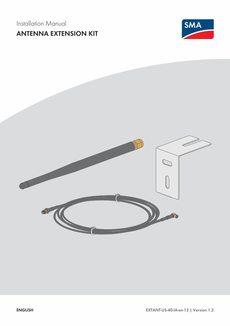
General Warnings
All electrical installations must be carried out in accordance with the local electrical standards and the NationalElectrical Code® ANSI/NFPA 70 or the Canadian Electrical Code® CSA C22.1. This document does not replaceand is not intended to replace any local, state, provincial, federal or national laws, regulations or codes applicableto the installation and use of the product, including without limitation applicable electrical safety codes. Allinstallations must conform with the laws, regulations, codes and standards applicable in the jurisdiction ofinstallation. SMA assumes no responsibility for the compliance or non-compliance with such laws or codes inconnection with the installation of the product. The product contains no user-serviceable parts. For all repair and maintenance, always return the unit to an authorized SMA Service Center. Before installing or using the product, read all of the instructions, cautions, and warnings in this manual. Wiring of the product must be made by qualified personnel only.
General Warnings SMA Solar Technology America LLC
Installation ManualEXTANT-US-40-IA-en-124

Table of Contents1 Information on this Document..................................................................................................... 6
1.1 Validity ............................................................................................................................................................. 61.2 Target group .................................................................................................................................................... 61.3 Symbols............................................................................................................................................................ 61.4 Typographies ................................................................................................................................................... 61.5 Nomenclature .................................................................................................................................................. 7
2 Safety ............................................................................................................................................ 82.1 Intended Use.................................................................................................................................................... 82.2 Safety Information ........................................................................................................................................... 8
3 Scope of Delivery ......................................................................................................................... 10
4 Mounting....................................................................................................................................... 114.1 Mounting position............................................................................................................................................ 114.2 Mounting the Antenna .................................................................................................................................... 12
5 Troubleshooting............................................................................................................................ 16
6 Decommissioning ......................................................................................................................... 176.1 Removing the Antenna .................................................................................................................................... 176.2 Disposing of the Product ................................................................................................................................. 17
7 Contact .......................................................................................................................................... 18
Table of ContentsSMA Solar Technology America LLC
Installation Manual 5EXTANT-US-40-IA-en-12

1 Information on this Document
1.1 ValidityThis document is valid for the Antenna Extension Kit (Product "EXTANT-US-40").You can find the latest version of this document at www.SMA-Solar.com.
1.2 Target groupThe tasks described in this document must only be performed by qualified persons. Qualified persons must have thefollowing skills:
• Training in how to deal with the dangers and risks associated with installing and using electrical devices andinstallations
• Training in the installation and commissioning of electrical devices and installations• Knowledge of how an inverter works and is operated• Knowledge of the applicable standards and directives• Knowledge of and compliance with this document and all safety information
1.3 SymbolsSymbol Explanation
Information that is important for a specific topic or goal, but is not safety-relevant
Indicates a requirement for meeting a specific goal
Desired result
A problem that might occur
1.4 TypographiesTypography Use Example
bold • Display texts• Elements on a user interface• Terminals• Elements to be selected• Elements to be entered
• The value can be found in the fieldEnergy.
• Select Settings.• Enter 10 in the field Minutes.
> • Connects several elements to beselected
• Select Settings > Date.
[Button][Key]
• Button or key to be selected or pressed • Select [Next].
1 Information on this Document SMA Solar Technology America LLC
Installation ManualEXTANT-US-40-IA-en-126
1.5 NomenclatureComplete designation Designation in this document
SMA Solar Technology America LLC SMA
SMA Solar Technology Canada Inc.
Antenna Extension Kit Antenna, product
PV system PV system
1 Information on this DocumentSMA Solar Technology America LLC
Installation Manual 7EXTANT-US-40-IA-en-12

2 Safety
2.1 Intended UseThe Antenna Extension Kit is an accessory set for SMA inverters: By installing the Antenna Extension Kit in an SMAinverter with WLAN interface, the inverter's radio range can be optimized within the WLAN network.The Antenna Extension Kit must only be installed in the following SMA inverters:
• SB3.0-1SP-US-40 (Sunny Boy 3.0-US)• SB3.8-1SP-US-40 (Sunny Boy 3.8-US)• SB5.0-1SP-US-40 (Sunny Boy 5.0-US)• SB6.0-1SP-US-40 (Sunny Boy 6.0-US)• SB7.0-1SP-US-40 (Sunny Boy 7.0-US)• SB7.7-1SP-US-40 (Sunny Boy 7.7-US)• STP 50-US-40 (Sunny Tripower CORE1-US)
The inverter still complies with the standard after the product has been installed.The product is approved for the US and Canadian market and must only be used in these markets.The product is suitable for indoor and outdoor use.Use this product only in accordance with the information provided in the enclosed documentation and with the locallyapplicable standards and directives. Any other application may cause personal injury or property damage.Alterations to the product, e.g. changes or modifications, are only permitted with the express written permission ofSMA. Unauthorized alterations will void guarantee and warranty claims and in most cases terminate the operatinglicense. SMA shall not be held liable for any damage caused by such changes.Any use of the product other than that described in the Intended Use section does not qualify as appropriate.The enclosed documentation is an integral part of this product. Keep the documentation in a convenient place forfuture reference and observe all instructions contained therein.
2.2 Safety InformationThis section contains safety information that must be observed at all times when working on or with the product.To prevent personal injury and property damage and to ensure long-term operation of the product, read this sectioncarefully and observe all safety information at all times.
Danger to life due to high voltages of the PV arrayWhen exposed to sunlight, the PV array generates dangerous DC voltage, which is present in the DC conductorsand the live components of the inverter. Touching the DC conductors or the live components can lead to lethalelectric shocks.
• Prior to performing any work on the inverter, always disconnect the inverter from voltage sources on the AC andDC sides as described in the inverter manual. When doing so, note that even if the DC load-break is switchedoff, there will be dangerous direct voltage present in the DC conductors of the inverter.
Danger to life due to electric shock from touching an ungrounded productTouching an ungrounded product can cause a lethal electric shock.
• Ensure that the product is integrated in the existing overvoltage protection.
2 Safety SMA Solar Technology America LLC
Installation ManualEXTANT-US-40-IA-en-128

Increased electromagnetic radiation through the antennaDuring operation, the antenna produces an electromagnetic field and can interfere with other devices (e.g.,pacemakers) due to electromagnetic interference.
• Persons must not remain closer than 20 cm (8 in) to the antenna for long periods of time.
Damage to the inverter or product due to electrostatic dischargeTouching electronic components can cause damage to or destroy the inverter or the product through electrostaticdischarge.
• Ground yourself before touching any component.
Damage to the inverter due to moisture ingress during electrical installation• Never open the inverter when it is raining or snowing, or the humidity is over 95%.• For attaching the conduits to the enclosure, only use UL-listed rain-tight conduit fittings or UL-listed conduit fittings
for wet locations complying with UL514B.• Seal all unused openings tightly.
Electrical installationsAll electrical installations must be carried out in accordance with the local standards and the National ElectricalCode® ANSI/NFPA 70 or the Canadian Electrical Code® CSA C22.1.
• Before connecting the inverter to the utility grid, contact your local grid operator. The electrical connection ofthe inverter must be carried out by qualified persons only.
• Ensure that no cables used for electrical connection are damaged.
2 SafetySMA Solar Technology America LLC
Installation Manual 9EXTANT-US-40-IA-en-12

3 Scope of DeliveryCheck the scope of delivery for completeness and any externally visible damage. Contact your distributor if the scopeof delivery is incomplete or damaged.
Figure 1: Components included in the scope of delivery
Position Quantity Designation
A 1 Antenna
B 1 Antenna bracket
C 1 Antenna cable (3 m (9.8 ft))
D 1 Cable gland with multi-hole seal
E 2 Bolt
F 2 Screw anchors
G 1 Quick reference guide for commissioning
3 Scope of Delivery SMA Solar Technology America LLC
Installation ManualEXTANT-US-40-IA-en-1210
4 Mounting
4.1 Mounting position
BAT
Max. 30V DC
USB
MFR
A
B
X1
X2
ANT.
FCC ID: SVF-KP20
IC: 9440A-KP20
A B
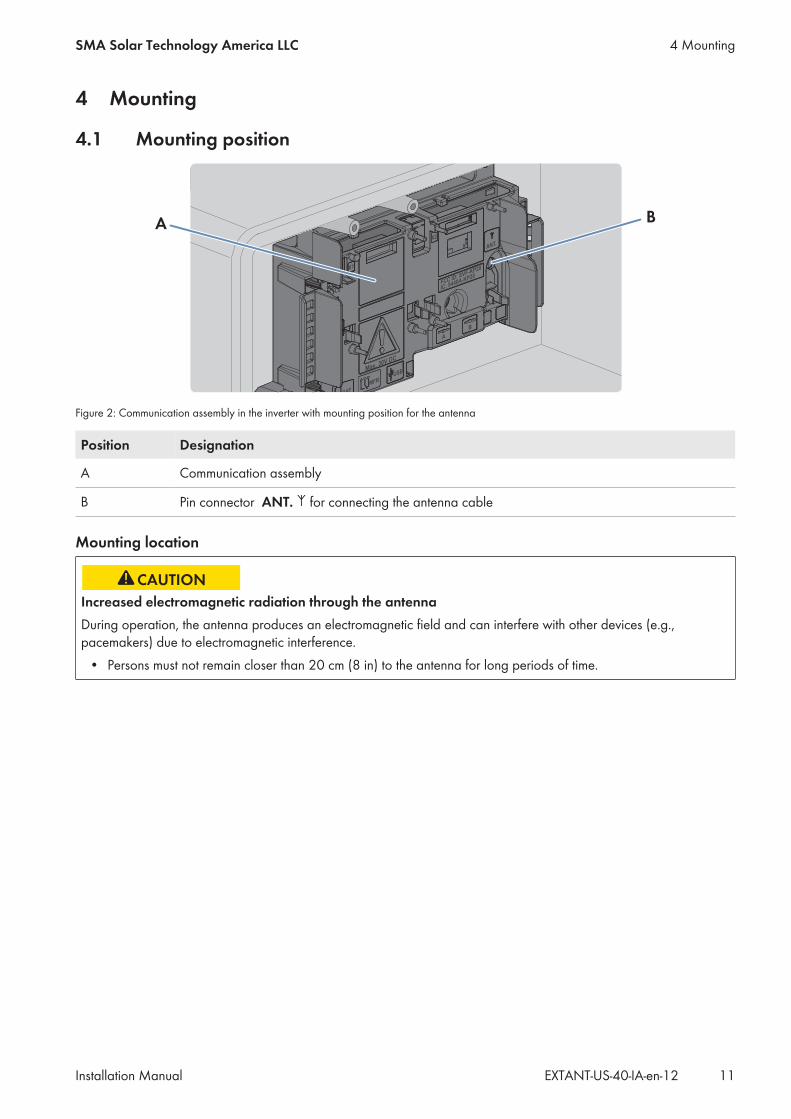
Figure 2: Communication assembly in the inverter with mounting position for the antenna
Position Designation
A Communication assembly
B Pin connector ANT. for connecting the antenna cable
Mounting location
Increased electromagnetic radiation through the antennaDuring operation, the antenna produces an electromagnetic field and can interfere with other devices (e.g.,pacemakers) due to electromagnetic interference.
• Persons must not remain closer than 20 cm (8 in) to the antenna for long periods of time.
4 MountingSMA Solar Technology America LLC
Installation Manual 11EXTANT-US-40-IA-en-12
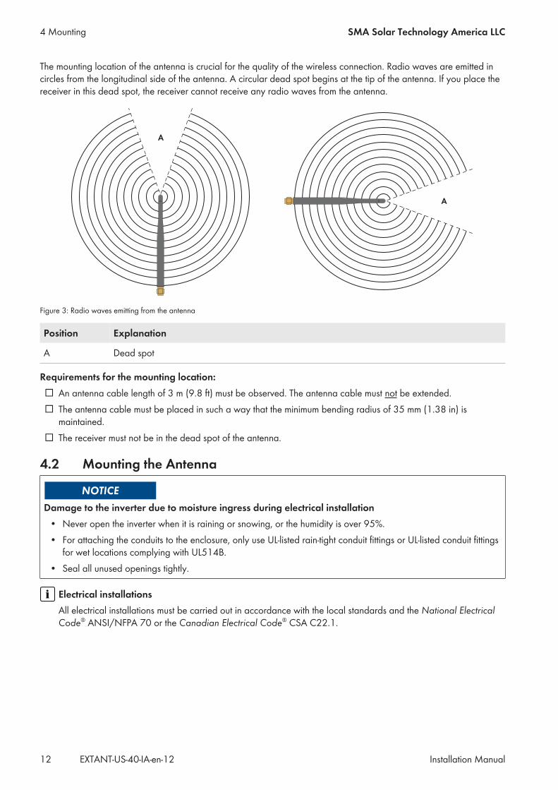
The mounting location of the antenna is crucial for the quality of the wireless connection. Radio waves are emitted incircles from the longitudinal side of the antenna. A circular dead spot begins at the tip of the antenna. If you place thereceiver in this dead spot, the receiver cannot receive any radio waves from the antenna.
Figure 3: Radio waves emitting from the antenna
Position Explanation
A Dead spot
Requirements for the mounting location:☐ An antenna cable length of 3 m (9.8 ft) must be observed. The antenna cable must not be extended.☐ The antenna cable must be placed in such a way that the minimum bending radius of 35 mm (1.38 in) is
maintained.☐ The receiver must not be in the dead spot of the antenna.
4.2 Mounting the Antenna
Damage to the inverter due to moisture ingress during electrical installation• Never open the inverter when it is raining or snowing, or the humidity is over 95%.• For attaching the conduits to the enclosure, only use UL-listed rain-tight conduit fittings or UL-listed conduit fittings
for wet locations complying with UL514B.• Seal all unused openings tightly.
Electrical installationsAll electrical installations must be carried out in accordance with the local standards and the National ElectricalCode® ANSI/NFPA 70 or the Canadian Electrical Code® CSA C22.1.
4 Mounting SMA Solar Technology America LLC
Installation ManualEXTANT-US-40-IA-en-1212

Procedure:
1.
Danger to life due to high voltages of the PV arrayWhen exposed to sunlight, the PV array generates dangerous DC voltage, which is present in the DC conductorsand the live components of the inverter. Touching the DC conductors or the live components can lead to lethalelectric shocks.
• Prior to performing any work on the inverter, always disconnect the inverter from voltage sources on the ACand DC sides as described in the inverter manual. When doing so, note that even if the DC load-break isswitched off, there will be dangerous direct voltage present in the DC conductors of the inverter.
2. If necessary, attach the cable gland to the inverter:• Push the sealing plug from the inside out of the enclosure
opening and retain it for later decommissioning.
• Unscrew the counter nut from the supplied cable gland.• Tighten the cable gland with the counter nut on the
inverter enclosure opening. 1
2
1
3. Connecting the antenna cable plug:• Unscrew the swivel nut from the cable gland.
1
2
4 MountingSMA Solar Technology America LLC
Installation Manual 13EXTANT-US-40-IA-en-12
• Remove the two-hole cable support sleeve from the cablegland.
• Route the antenna cable with the cable end with the plugthrough the swivel nut and the desired hole of the two-hole cable support sleeve.
• Push the two-cable support sleeve along with the antenna cable back into the cable gland. Ensure that anyunused openings of the two-hole cable support sleeve are sealed with sealing plugs.
• Screw the swivel nut of the cable gland on loosely.• Remove the protective cover of pin connector ANT. on the communication assembly (if present).• Insert the plug of the antenna cable into the pin connector
ANT. on the communication assembly until it snaps intoplace. Observe the prescribed cable route (seeSection 4.1, page 11).
BAT
Max. 30V DC
USB
MFR
A
B
X1
X2
ANT.
FCC ID: SVF-KP20
IC: 9440A-KP20
SPS
A
B
D-IN
ANT.
• Fasten the swivel nut on the cable gland hand-tight. This will secure the antenna cable.4. Installing the antenna bracket:
• Considering the dead spot of the antenna, move the antenna bracket to the desired position on the wall andhold it firmly.
• Mark positions of drill holes if necessary and drill two holes with 6 mm (0.24 in) diameter each at themarked points and insert screw anchors.
• Attach the antenna bracket to the wall with the screws.5. Attaching the antenna cable and the antenna to the antenna bracket:
4 Mounting SMA Solar Technology America LLC
Installation ManualEXTANT-US-40-IA-en-1214
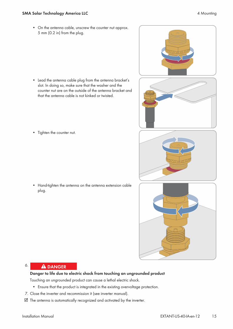
• On the antenna cable, unscrew the counter nut approx.5 mm (0.2 in) from the plug.
• Lead the antenna cable plug from the antenna bracket’sslot. In doing so, make sure that the washer and thecounter nut are on the outside of the antenna bracket andthat the antenna cable is not kinked or twisted.
• Tighten the counter nut.
• Hand-tighten the antenna on the antenna extension cableplug.
6.
Danger to life due to electric shock from touching an ungrounded productTouching an ungrounded product can cause a lethal electric shock.
• Ensure that the product is integrated in the existing overvoltage protection.7. Close the inverter and recommission it (see inverter manual).☑ The antenna is automatically recognized and activated by the inverter.
4 MountingSMA Solar Technology America LLC
Installation Manual 15EXTANT-US-40-IA-en-12

5 TroubleshootingProblem Cause and corrective measures
The radio range has not im-proved despite the antenna.
The problem can be caused by one of the following:• The inverter has not recognized the antenna automatically.• The antenna is not installed correctly or an unapproved antenna has been
used.• The receiver is placed in the dead spot.
Corrective measures:• Ensure that the antenna has been recognized by the inverter:
– Log in to the user interface of the inverter as Installer (see the invertermanual).
– Instantaneous values > Plant communication > WLAN.– Check whether the parameter Antenna Typeis set on External
Antenna.If the value External Antenna is not set, set the antenna type (seeinverter manual).
• Ensure that the antenna of type “EXTANT-US-40” is installed correctly andthat only the supplied antenna cable was used.
• Ensure that the receiver is not placed in the dead spot .
5 Troubleshooting SMA Solar Technology America LLC
Installation ManualEXTANT-US-40-IA-en-1216

6 Decommissioning
6.1 Removing the AntennaRequired tools:☐ Long-nosed pliers
Procedure:
1.
Danger to life due to high voltages of the PV arrayWhen exposed to sunlight, the PV array generates dangerous DC voltage, which is present in the DC conductorsand the live components of the inverter. Touching the DC conductors or the live components can lead to lethalelectric shocks.
• Prior to performing any work on the inverter, always disconnect the inverter from voltage sources on the ACand DC sides as described in the inverter manual. When doing so, note that even if the DC load-break isswitched off, there will be dangerous direct voltage present in the DC conductors of the inverter.
2. Pull the antenna cable plug out of pin connector ANT. of thecommunication assembly using long-nosed pliers. Ensure thatthe antenna cable is pulled out at 90° to the communicationassembly so that the plug does not get caught.
3. Unscrew the swivel nut from the cable gland.4. Unscrew and remove the counter nut of the cable gland.5. If necessary, remove the cable gland and antenna cable from the inverter.6. If necessary, seal the enclosure opening of the inverter with the corresponding sealing plug.7. Close the inverter and recommission it (see inverter manual).8. At the antenna bracket, unscrew the antenna from the antenna cable plug.9. Unscrew the counter nut from the plug of the antenna cable.
10. Remove the antenna cable from the antenna bracket.11. Remove the screws of the antenna bracket.12. Unscrew and remove the antenna bracket.
6.2 Disposing of the Product• Dispose of the product in accordance with the locally applicable disposal regulations for electronic waste.
6 DecommissioningSMA Solar Technology America LLC
Installation Manual 17EXTANT-US-40-IA-en-12
7 ContactIf you have technical problems with our products, please contact the SMA Service Line. We require the followinginformation in order to provide you with the necessary assistance:
• Inverters:– Serial number– Firmware version– Special country-specific settings (if applicable)
• Detailed description of the problem
United States/Estados Unidos
SMA Solar TechnologyAmerica LLCRocklin, CA
Toll free for USA, Canada and Puerto Rico / Llamada gratuita en EE.UU., Canadá y Puerto Rico:+1 877-MY-SMATech (+1 877-697-6283)International / Internacional: +1 916 625-0870
Canada/Canadá
SMA Solar TechnologyCanada Inc.Mississauga
Toll free for Canada / gratuit pour le Canada:+1 877-MY-SMATech (+1 877-697-6283)
7 Contact SMA Solar Technology America LLC
Installation ManualEXTANT-US-40-IA-en-1218


www.SMA-Solar.com

![Design of Ionofree Micro Strip Quad Helix Antenna for ... · antenna, bifilar helices antenna, microstrip antenna, quadrafilar helix antenna. ... Helical antenna [1],[2] is broadband](https://img.pdfslide.us/doc/110x75/5b9506e809d3f2ea5c8b5a04/design-of-ionofree-micro-strip-quad-helix-antenna-for-antenna-bifilar-helices.jpg)