Embed Size (px)
Citation preview

Installation Data
Installation Manual
All Button and OneTouchTM Control Systems
WARNINGFOR YOUR SAFETY - This product must be installed and serviced by a professional pool/spa service technician. The procedures in this manual must be followed exactly. Failure to follow warning notices and instructions may result in property damage, serious injury, or death.
Pool/Spa Combination Systems and Pool/Spa Only Systems
She
et #
6594
, Rev
. K

Page �
Table of ContentsSection 1. Important Safety Instructions ........... 4
Section 2. System Overview ............................. 6
2.1 Package Contents ........................... 62.2 SystemComponentSpecifications
and Dimensions ............................... 72.3 Basic Plumbing ............................... 8
Section 3. Installation ........................................ 10
3.1 Power Center Mounting .................. 103.2 High Voltage Wiring ....................... 103.3 Low Voltage Wiring ........................ 143.4 Heater Connection .......................... 153.5 Temperature Sensors ....................... 183.6 Jandy Valve Actuators ..................... 183.7 Auxiliary Power Centers ................. 183.8 All Button Control Panel Installation .. 193.9 OneTouch Control Panel Installation ..203.10 Wireless OneTouch Control Panel
Installation ...................................... 22
Section 4. System Startup ................................. 24
4.1 All Button Programming ............... 244.2 All Button Reset and Display
Messages ........................................ 264.3 OneTouch Programming ................ 264.4 OneTouch Reset and Display
Messages ......................................... 274.5 All Button and OneTouch System
Defaults and General Modes .......... 284.6 All Button Menu Flow Chart .......... 304.7 OneTouch Menu Flow Chart .......... 31
Section 5. Troubleshooting ................................ 32
5.1 All Button and OneTouch Quick Troubleshooting Guide ................... 32
5.2 Wireless OneTouch Quick Troubleshooting Guide ................... 33
Section 6. Power Center Wiring Diagram ......... 35
Section 7. Power Center PCB DIP Switch Settings ............................................. 36
7.1 DIP Switch Functions ..................... 367.2 DIP Switch Settings for Pool and Spa
Combination ................................... 377.3 DIP Switch Settings for Pool or
Spa Only ......................................... 38Section 8. General, Water Feature and Light
Aux Labels ....................................... 39
Warranty .......................................................... 40
DATE OF INSTAllATION
INSTAllER INFORMATION
INITIAl PRESSURE GAUGE READING (WITh ClEAN FIlTER)
PUMP MODEl hORSEPOWER
FIlTER MODEl SERIAl NUMBER
CONTROl PANEl MODEl SERIAl NUMBER
NOTES:
EqUIPMENT INFORMATION RECORD
Page 4
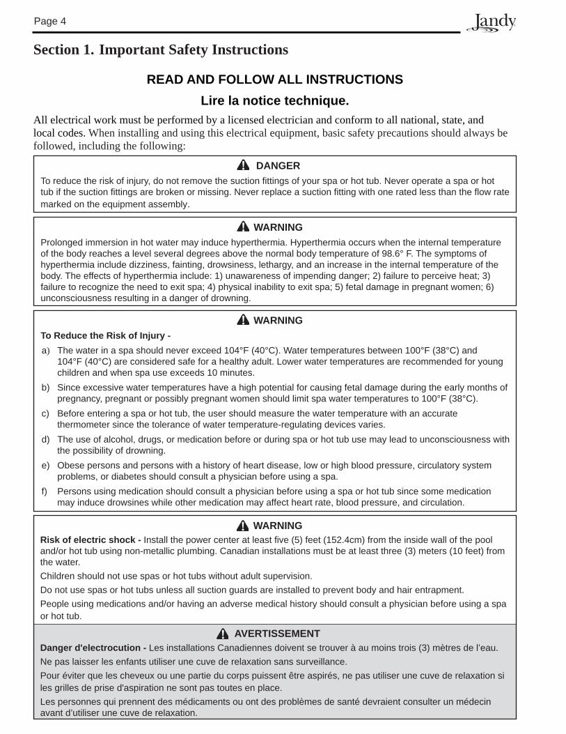
Section 1. Important Safety Instructions
READ AND FOllOW All INSTRUCTIONSlire la notice technique.
All electrical work must be performed by a licensed electrician and conform to all national, state, and local codes. When installing and using this electrical equipment, basic safety precautions should always be followed, including the following:
WARNINGProlonged immersion in hot water may induce hyperthermia. Hyperthermia occurs when the internal temperature of the body reaches a level several degrees above the normal body temperature of 98.6° F. The symptoms of hyperthermia include dizziness, fainting, drowsiness, lethargy, and an increase in the internal temperature of the body. The effects of hyperthermia include: 1) unawareness of impending danger; 2) failure to perceive heat; �) failure to recognize the need to exit spa; 4) physical inability to exit spa; 5) fetal damage in pregnant women; 6) unconsciousness resulting in a danger of drowning.
DANGERTo reduce the risk of injury, do not remove the suction fittings of your spa or hot tub. Never operate a spa or hot tub if the suction fittings are broken or missing. Never replace a suction fitting with one rated less than the flow rate marked on the equipment assembly.
WARNINGTo Reduce the Risk of Injury -a) The water in a spa should never exceed 104°F (40°C). Water temperatures between 100°F (�8°C) and
104°F (40°C) are considered safe for a healthy adult. Lower water temperatures are recommended for young children and when spa use exceeds 10 minutes.
b) Since excessive water temperatures have a high potential for causing fetal damage during the early months of pregnancy, pregnant or possibly pregnant women should limit spa water temperatures to 100°F (�8°C).
c) Before entering a spa or hot tub, the user should measure the water temperature with an accurate thermometer since the tolerance of water temperature-regulating devices varies.
d) The use of alcohol, drugs, or medication before or during spa or hot tub use may lead to unconsciousness with the possibility of drowning.
e) Obese persons and persons with a history of heart disease, low or high blood pressure, circulatory system problems, or diabetes should consult a physician before using a spa.
f) Persons using medication should consult a physician before using a spa or hot tub since some medication may induce drowsines while other medication may affect heart rate, blood pressure, and circulation.
WARNINGRisk of electric shock - Install the power center at least five (5) feet (152.4cm) from the inside wall of the pool and/or hot tub using non-metallic plumbing. Canadian installations must be at least three (�) meters (10 feet) from the water. Children should not use spas or hot tubs without adult supervision.Do not use spas or hot tubs unless all suction guards are installed to prevent body and hair entrapment.People using medications and/or having an adverse medical history should consult a physician before using a spa or hot tub.
AVERTISSEMENTDanger d'electrocution - Les installations Canadiennes doivent se trouver à au moins trois (�) mètres de l’eau.Ne pas laisser les enfants utiliser une cuve de relaxation sans surveillance.Pour éviter que les cheveux ou une partie du corps puissent être aspirés, ne pas utiliser une cuve de relaxation si les grilles de prise d'aspiration ne sont pas toutes en place.Les personnes qui prennent des médicaments ou ont des problèmes de santé devraient consulter un médecin avant d’utiliser une cuve de relaxation.
Page 5
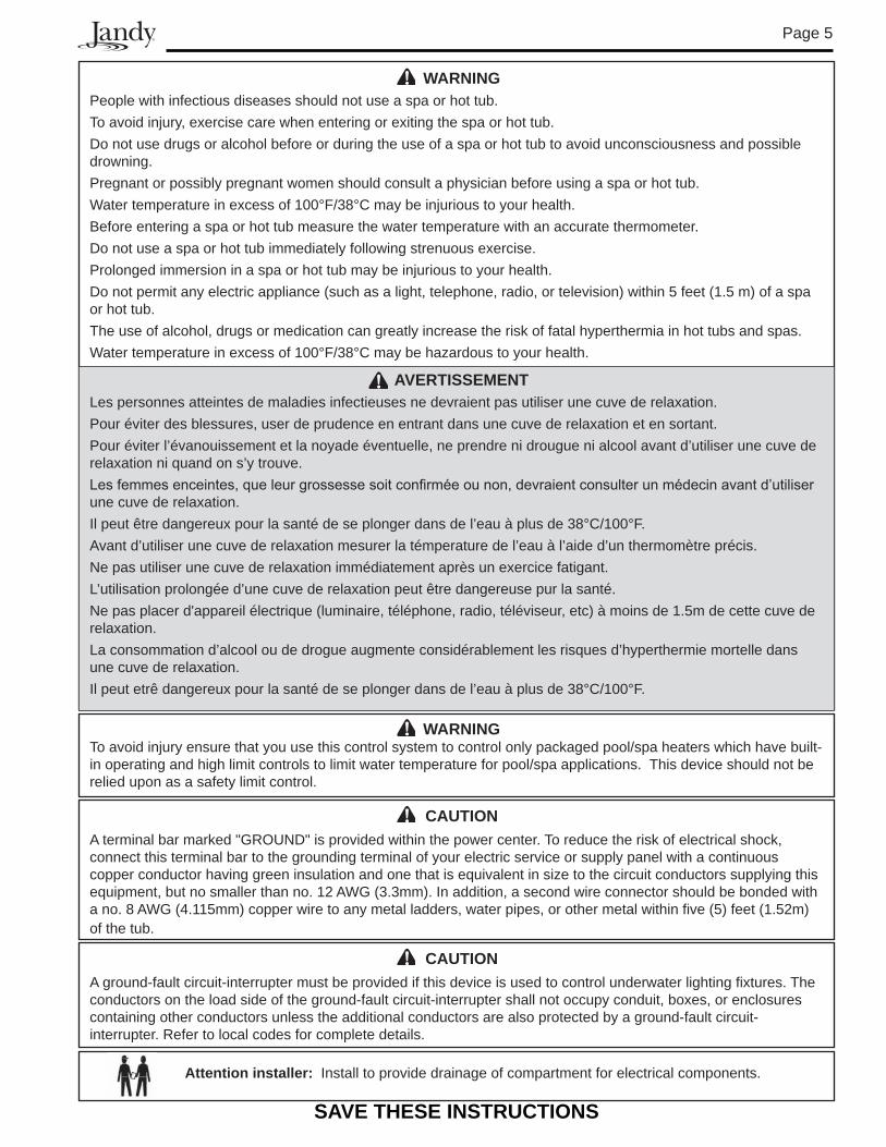
CAUTIONA ground-fault circuit-interrupter must be provided if this device is used to control underwater lighting fixtures. The conductors on the load side of the ground-fault circuit-interrupter shall not occupy conduit, boxes, or enclosures containing other conductors unless the additional conductors are also protected by a ground-fault circuit-interrupter. Refer to local codes for complete details.
CAUTIONA terminal bar marked "GROUND" is provided within the power center. To reduce the risk of electrical shock, connect this terminal bar to the grounding terminal of your electric service or supply panel with a continuous copper conductor having green insulation and one that is equivalent in size to the circuit conductors supplying this equipment, but no smaller than no. 12 AWG (�.�mm). In addition, a second wire connector should be bonded with a no. 8 AWG (4.115mm) copper wire to any metal ladders, water pipes, or other metal within five (5) feet (1.52m) of the tub.
SAVE ThESE INSTRUCTIONS
WARNINGPeople with infectious diseases should not use a spa or hot tub.To avoid injury, exercise care when entering or exiting the spa or hot tub.Do not use drugs or alcohol before or during the use of a spa or hot tub to avoid unconsciousness and possible drowning.Pregnant or possibly pregnant women should consult a physician before using a spa or hot tub. Water temperature in excess of 100°F/�8°C may be injurious to your health. Before entering a spa or hot tub measure the water temperature with an accurate thermometer. Do not use a spa or hot tub immediately following strenuous exercise.Prolonged immersion in a spa or hot tub may be injurious to your health.Do not permit any electric appliance (such as a light, telephone, radio, or television) within 5 feet (1.5 m) of a spa or hot tub.The use of alcohol, drugs or medication can greatly increase the risk of fatal hyperthermia in hot tubs and spas.Water temperature in excess of 100°F/�8°C may be hazardous to your health.
AVERTISSEMENTLes personnes atteintes de maladies infectieuses ne devraient pas utiliser une cuve de relaxation.Pour éviter des blessures, user de prudence en entrant dans une cuve de relaxation et en sortant.Pour éviter l’évanouissement et la noyade éventuelle, ne prendre ni drougue ni alcool avant d’utiliser une cuve de relaxation ni quand on s’y trouve.Les femmes enceintes, que leur grossesse soit confirmée ou non, devraient consulter un médecin avant d’utiliser une cuve de relaxation.Il peut être dangereux pour la santé de se plonger dans de l’eau à plus de �8°C/100°F.Avant d’utiliser une cuve de relaxation mesurer la témperature de l’eau à l’aide d’un thermomètre précis.Ne pas utiliser une cuve de relaxation immédiatement après un exercice fatigant.L’utilisation prolongée d’une cuve de relaxation peut être dangereuse pur la santé.Ne pas placer d'appareil électrique (luminaire, téléphone, radio, téléviseur, etc) à moins de 1.5m de cette cuve de relaxation.La consommation d’alcool ou de drogue augmente considérablement les risques d’hyperthermie mortelle dans une cuve de relaxation.Il peut etrê dangereux pour la santé de se plonger dans de l’eau à plus de �8°C/100°F.
Attention installer: Install to provide drainage of compartment for electrical components.
WARNINGTo avoid injury ensure that you use this control system to control only packaged pool/spa heaters which have built-in operating and high limit controls to limit water temperature for pool/spa applications. This device should not be relied upon as a safety limit control.
Page 6
Section 2. System Overview
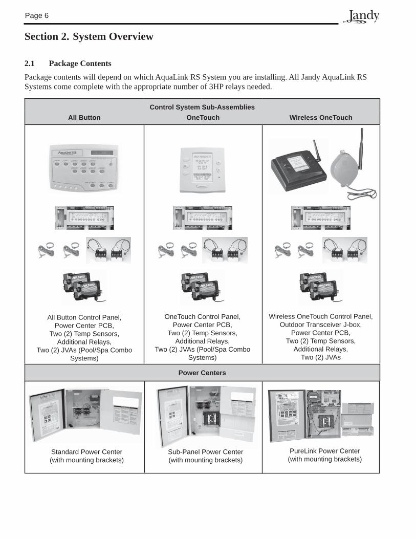
2.1 Package Contents
Package contents will depend on which AquaLink RS System you are installing. All Jandy AquaLink RS Systems come complete with the appropriate number of 3HP relays needed.
Control System Sub-AssembliesAll Button OneTouch Wireless OneTouch
Power Centers
OneTouch Control Panel,Power Center PCB,
Two (2) Temp Sensors,Additional Relays,
Two (2) JVAs (Pool/Spa Combo Systems)
All Button Control Panel,Power Center PCB,
Two (2) Temp Sensors,Additional Relays,
Two (2) JVAs (Pool/Spa Combo Systems)
Wireless OneTouch Control Panel, Outdoor Transceiver J-box,
Power Center PCB,Two (2) Temp Sensors,
Additional Relays, Two (2) JVAs
Standard Power Center(with mounting brackets)
Sub-Panel Power Center(with mounting brackets)
PureLink Power Center(with mounting brackets)
Page �
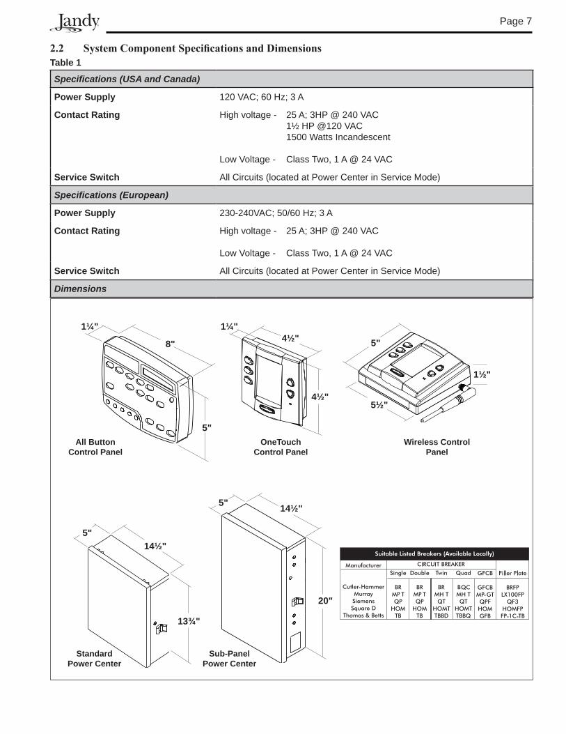
2.2 SystemComponentSpecificationsandDimensionsTable 1
Specifications (USA and Canada)
Power Supply 120 VAC; 60 Hz; � A
Contact Rating High voltage - 25 A; �HP @ 240 VAC 1½ HP @120 VAC 1500 Watts Incandescent
Low Voltage - Class Two, 1 A @ 24 VAC
Service Switch All Circuits (located at Power Center in Service Mode)
Specifications (European)
Power Supply 2�0-240VAC; 50/60 Hz; � A
Contact Rating High voltage - 25 A; �HP @ 240 VAC
Low Voltage - Class Two, 1 A @ 24 VAC
Service Switch All Circuits (located at Power Center in Service Mode)
Dimensions
8"
5"
1¼"
5½"
1½"
5"4½"
4½"
1¼"
All Button Control Panel
OneTouchControl Panel
Wireless Control Panel
Standard Power Center
5"14½"
13¾"
Sub-PanelPower Center
20"
14½"5"
Page 8
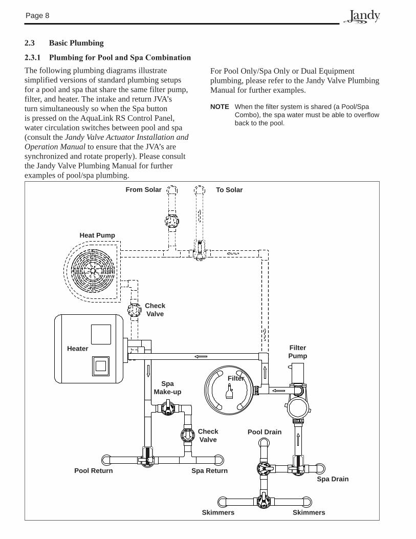
2.3 Basic Plumbing
2.3.1 PlumbingforPoolandSpaCombinationThe following plumbing diagrams illustrate simplified versions of standard plumbing setups for a pool and spa that share the same filter pump, filter, and heater. The intake and return JVA’s turn simultaneously so when the Spa button is pressed on the AquaLink RS Control Panel, water circulation switches between pool and spa (consult the Jandy Valve Actuator Installation and Operation Manual to ensure that the JVA’s are synchronized and rotate properly). Please consult the Jandy Valve Plumbing Manual for further examples of pool/spa plumbing.
heater
Filter
FilterPump
Pool Drain
Spa DrainSpa ReturnPool Return
CheckValve
SpaMake-up
CheckValve
heat Pump
SkimmersSkimmers
From Solar To Solar
For Pool Only/Spa Only or Dual Equipment plumbing, please refer to the Jandy Valve Plumbing Manual for further examples.
NOTE When the filter system is shared (a Pool/Spa Combo), the spa water must be able to overflow back to the pool.
Page 9
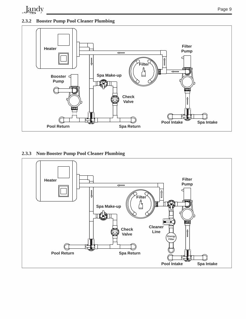
2.3.2 Booster Pump Pool Cleaner Plumbing
heater
Filter
FilterPump
Pool Intake Spa IntakeSpa ReturnPool Return
CheckValve
Spa Make-upBoosterPump
2.3.3 Non-Booster Pump Pool Cleaner Plumbing
heater
Filter
FilterPump
Pool Intake Spa Intake
Spa ReturnPool Return
CheckValve
Spa Make-up
EnergyFilter
Cleanerline
Page 10
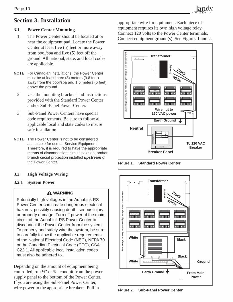
3.1 Power Center Mounting1. The Power Center should be located at or
near the equipment pad. Locate the Power Center at least five (5) feet or more away from pool/spa and five (5) feet off the ground. All national, state, and local codes are applicable.
NOTE For Canadian installations, the Power Center must be at least three (�) meters (9.8 feet) away from the pool/spa and 1.5 meters (5 feet) above the ground.
2. Use the mounting brackets and instructions provided with the Standard Power Center and/or Sub-Panel Power Center.
3. Sub-Panel Power Centers have special code requirements. Be sure to follow all applicable local and state codes to insure safe installation.
NOTE The Power Center is not to be considered as suitable for use as Service Equipment. Therefore, it is required to have the appropriate means of disconnection, circuit isolation, and/or branch circuit protection installed upstream of the Power Center.
3.2 High Voltage Wiring
3.2.1 System Power
Figure 2. Sub-Panel Power Center
Transformer
Earth Ground
Black White
Prim
ary
low
vol
tage
race
way
, do
not r
un h
igh
volta
ge in
this
com
part
men
t
From Main Power
Ground
White
WhiteBlack
Black
Transformer
Earth Ground
Breaker Panel
To 120 VAC Breaker
Neutral
Black White
Wire nut to120 VAC power
low
vol
tage
race
way
, do
not r
un h
igh
volta
ge in
this
com
part
men
t
Prim
ary
Figure 1. Standard Power Center
Section 3. Installation
WARNINGPotentially high voltages in the AquaLink RS Power Center can create dangerous electrical hazards, possibly causing death, serious injury or property damage. Turn off power at the main circuit of the AquaLink RS Power Center to disconnect the Power Center from the system. To properly and safely wire the system, be sure to carefully follow the applicable requirements of the National Electrical Code (NEC), NFPA �0 or the Canadian Electrical Code (CEC), CSA C22.1. All applicable local installation codes must also be adhered to.
Depending on the amount of equipment being controlled, run ½" or ¾" conduit from the power supply panel to the bottom of the Power Center. If you are using the Sub-Panel Power Center, wire power to the appropriate breakers. Pull in
appropriate wire for equipment. Each piece of equipment requires its own high voltage relay. Connect 120 volts to the Power Center terminals. Connect equipment ground(s). See Figures 1 and 2.
Page 11
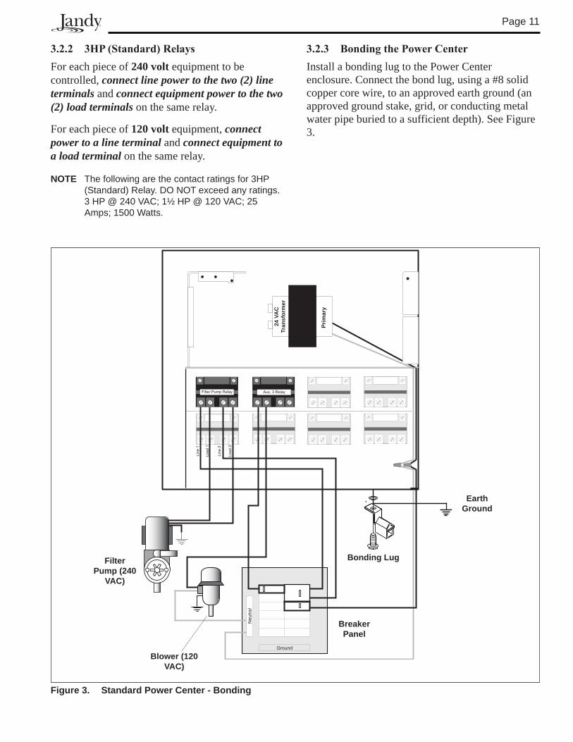
3.2.3 BondingthePowerCenterInstall a bonding lug to the Power Center enclosure. Connect the bond lug, using a #8 solid copper core wire, to an approved earth ground (an approved ground stake, grid, or conducting metal water pipe buried to a sufficient depth). See Figure 3.
3.2.2 3HP(Standard)RelaysFor each piece of 240 volt equipment to be controlled, connect line power to the two (2) line terminals and connect equipment power to the two (2) load terminals on the same relay.
For each piece of 120 volt equipment, connect power to a line terminal and connect equipment to a load terminal on the same relay.
NOTE The following are the contact ratings for �HP (Standard) Relay. DO NOT exceed any ratings. � HP @ 240 VAC; 1½ HP @ 120 VAC; 25 Amps; 1500 Watts.
Figure 3. Standard Power Center - Bonding
Bonding lug
Earth Ground
Breaker Panel
Blower (120 VAC)
Filter Pump (240
VAC)
Prim
ary
24 V
AC
Tr
ansf
orm
er
Page 12
3.2.4 UnderwaterLightingGFCIWiring
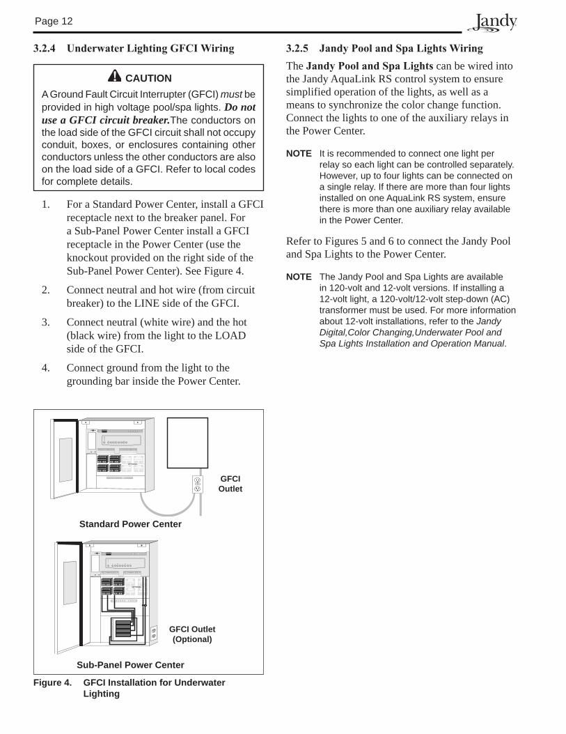
Figure 4. GFCI Installation for Underwater lighting
GFCI Outlet
OPTIONAL
Standard Power Center
GFCI Outlet(Optional)
OPTIONAL
Sub-Panel Power Center
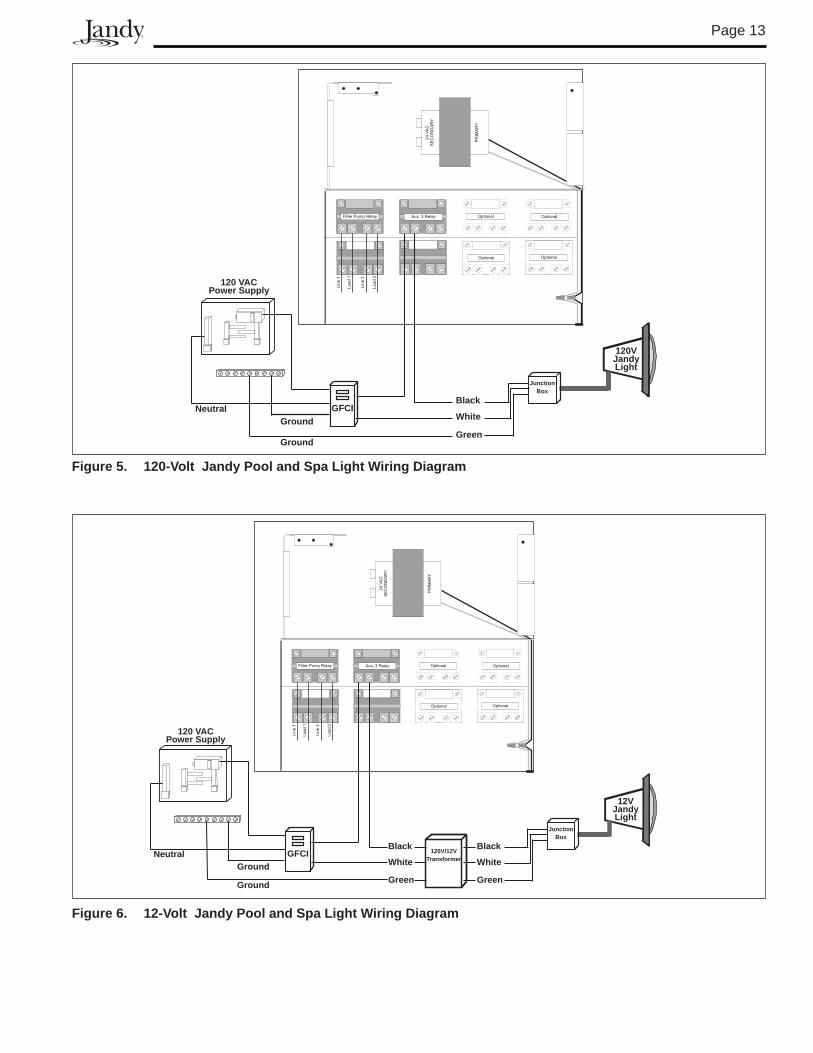
3.2.5 JandyPoolandSpaLightsWiringThe JandyPoolandSpaLights can be wired into the Jandy AquaLink RS control system to ensure simplified operation of the lights, as well as a means to synchronize the color change function. Connect the lights to one of the auxiliary relays in the Power Center.
NOTE It is recommended to connect one light per relay so each light can be controlled separately. However, up to four lights can be connected on a single relay. If there are more than four lights installed on one AquaLink RS system, ensure there is more than one auxiliary relay available in the Power Center.
Refer to Figures 5 and 6 to connect the Jandy Pool and Spa Lights to the Power Center.
NOTE The Jandy Pool and Spa Lights are available in 120-volt and 12-volt versions. If installing a 12-volt light, a 120-volt/12-volt step-down (AC) transformer must be used. For more information about 12-volt installations, refer to the Jandy Digital,Color Changing,Underwater Pool and Spa Lights Installation and Operation Manual.
CAUTIONA Ground Fault Circuit Interrupter (GFCI) must be provided in high voltage pool/spa lights. Do not use a GFCI circuit breaker.The conductors on the load side of the GFCI circuit shall not occupy conduit, boxes, or enclosures containing other conductors unless the other conductors are also on the load side of a GFCI. Refer to local codes for complete details.
1. For a Standard Power Center, install a GFCI receptacle next to the breaker panel. For a Sub-Panel Power Center install a GFCI receptacle in the Power Center (use the knockout provided on the right side of the Sub-Panel Power Center). See Figure 4.
2. Connect neutral and hot wire (from circuit breaker) to the LINE side of the GFCI.
3. Connect neutral (white wire) and the hot (black wire) from the light to the LOAD side of the GFCI.
4. Connect ground from the light to the grounding bar inside the Power Center.
Page 1�
GFCIBlack
White
Green
120VJandyLight
Ground
GroundNeutral
120 VACPower Supply
JunctionBox
Figure 5. 120-Volt Jandy Pool and Spa light Wiring Diagram
Figure 6. 12-Volt Jandy Pool and Spa light Wiring Diagram
GFCI
Ground
GroundNeutral
Black
White
Green
12VJandyLight
Black
White
Green
120V/12VTransformer
120 VACPower Supply
JunctionBox
Page 14
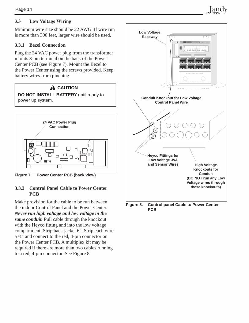
Figure 8. Control panel Cable to Power Center PCB
Conduit Knockout for low Voltage Control Panel Wire
heyco Fittings for low Voltage JVA and Sensor Wires
low Voltage Raceway
high Voltage Knockouts for
Conduit (DO NOT run any low Voltage wires through
these knockouts)
3.3 LowVoltageWiring
Minimum wire size should be 22 AWG. If wire run is more than 300 feet, larger wire should be used.
3.3.1 Bezel ConnectionPlug the 24 VAC power plug from the transformer into its 3-pin terminal on the back of the Power Center PCB (see Figure 7). Mount the Bezel to the Power Center using the screws provided. Keep battery wires from pinching.
CAUTIONDO NOT INSTAll BATTERY until ready to power up system.
3.3.2 Control Panel Cable to Power Center PCB
Make provision for the cable to be run between the indoor Control Panel and the Power Center. Never run high voltage and low voltage in the same conduit. Pull cable through the knockout with the Heyco fitting and into the low voltage compartment. Strip back jacket 6". Strip each wire a ¼" and connect to the red, 4-pin connector on the Power Center PCB. A multiplex kit may be required if there are more than two cables running to a red, 4-pin connector. See Figure 8.
Figure 7. Power Center PCB (back view)
24 VAC Power Plug Connection
Page 15
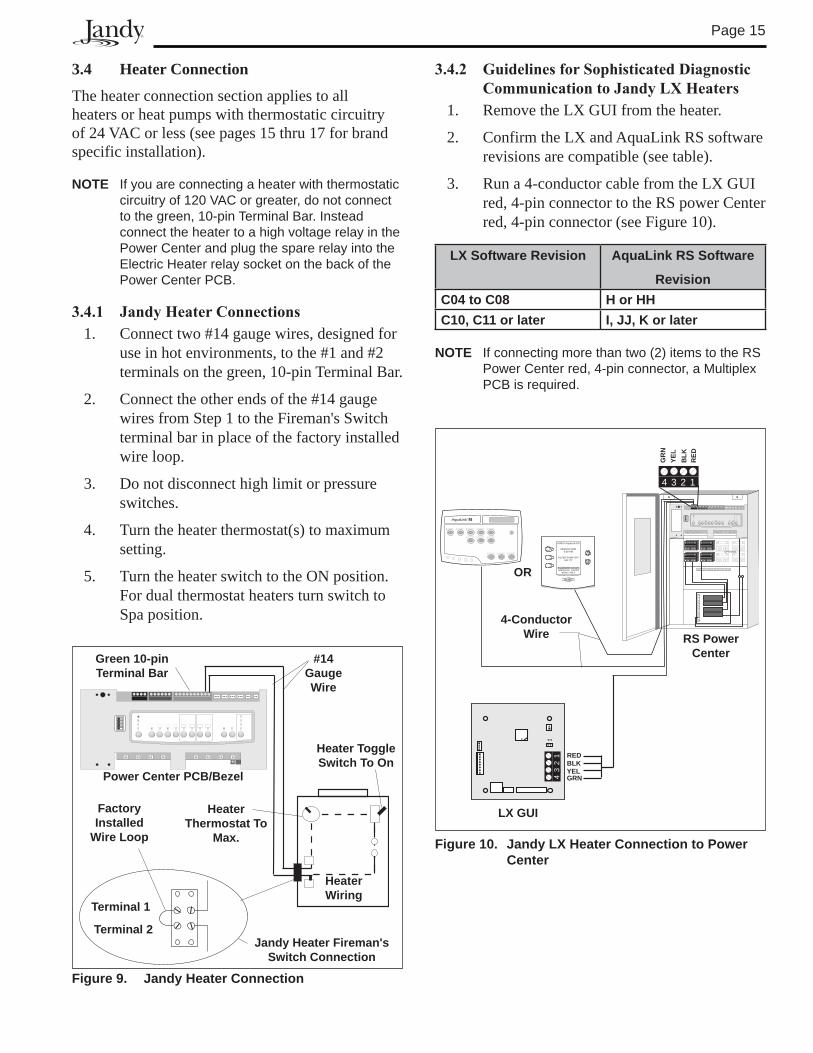
3.4 Heater Connection
The heater connection section applies to all heaters or heat pumps with thermostatic circuitry of 24 VAC or less (see pages 15 thru 17 for brand specific installation).
NOTE If you are connecting a heater with thermostatic circuitry of 120 VAC or greater, do not connect to the green, 10-pin Terminal Bar. Instead connect the heater to a high voltage relay in the Power Center and plug the spare relay into the Electric Heater relay socket on the back of the Power Center PCB.
3.4.1 JandyHeaterConnections1. Connect two #14 gauge wires, designed for
use in hot environments, to the #1 and #2 terminals on the green, 10-pin Terminal Bar.
2. Connect the other ends of the #14 gauge wires from Step 1 to the Fireman's Switch terminal bar in place of the factory installed wire loop.
3. Do not disconnect high limit or pressure switches.
4. Turn the heater thermostat(s) to maximum setting.
5. Turn the heater switch to the ON position. For dual thermostat heaters turn switch to Spa position.
Figure 9. Jandy heater Connection
Power Center PCB/Bezel
heater Wiring
#14 Gauge Wire
Green 10-pin Terminal Bar
heater Thermostat To
Max.
heater Toggle Switch To On
Terminal 1
Terminal 2Jandy heater Fireman's
Switch Connection
Factory Installed
Wire loop
3.4.2 GuidelinesforSophisticatedDiagnosticCommunicationtoJandyLXHeaters
1. Remove the LX GUI from the heater.
2. Confirm the LX and AquaLink RS software revisions are compatible (see table).
3. Run a 4-conductor cable from the LX GUI red, 4-pin connector to the RS power Center red, 4-pin connector (see Figure 10).
lX Software Revision Aqualink RS Software
RevisionC04 to C08 h or hhC10, C11 or later I, JJ, K or later
NOTE If connecting more than two (2) items to the RS Power Center red, 4-pin connector, a Multiplex PCB is required.
OPTIONAL
4 3 2 1
43
21 RED
BLKYELGRN
RE
DB
LK
YE
L
GR
N
®
JANDY AquaLink RS
FILTER PUMP OFFAIR 79°
06/26/04 MON6:00 PM
EQUIPMENT ON/OFFONETOUCH ON/OFF
MENU / HELP
4-Conductor Wire
lX GUI
OR
RS Power Center
Figure 10. Jandy lX heater Connection to Power Center
Page 16
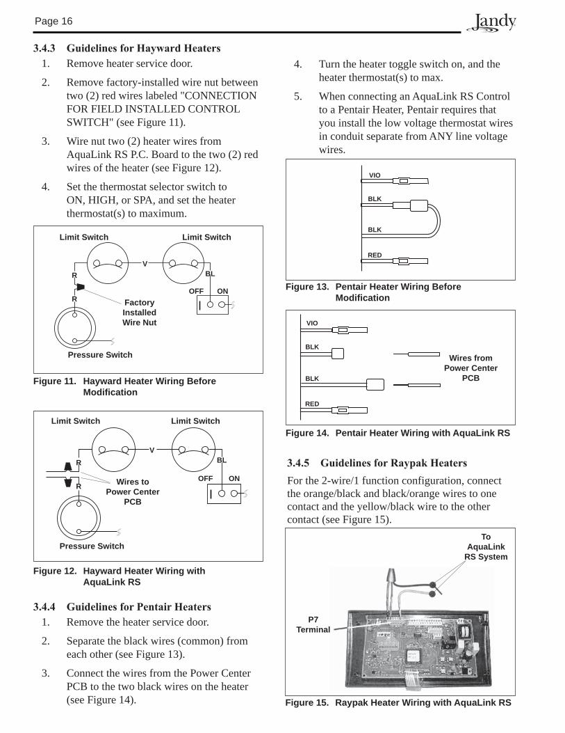
3.4.3 GuidelinesforHaywardHeaters1. Remove heater service door.
2. Remove factory-installed wire nut between two (2) red wires labeled "CONNECTION FOR FIELD INSTALLED CONTROL SWITCH" (see Figure 11).
3. Wire nut two (2) heater wires from AquaLink RS P.C. Board to the two (2) red wires of the heater (see Figure 12).
4. Set the thermostat selector switch to ON, HIGH, or SPA, and set the heater thermostat(s) to maximum.
3.4.4 GuidelinesforPentairHeaters1. Remove the heater service door.
2. Separate the black wires (common) from each other (see Figure 13).
3. Connect the wires from the Power Center PCB to the two black wires on the heater (see Figure 14).
3.4.5 GuidelinesforRaypakHeatersFor the 2-wire/1 function configuration, connect the orange/black and black/orange wires to one contact and the yellow/black wire to the other contact (see Figure 15).
limit Switch
Factory Installed Wire Nut
R
limit Switch
R
V
OFF ON
Bl
Pressure Switch
Figure 11. hayward heater Wiring Before Modification
ON
Bl
limit Switch limit Switch
R
R
V
OFF
Pressure Switch
Wires to Power Center
PCB
Figure 12. hayward heater Wiring with Aqualink RS
Figure 13. Pentair heater Wiring Before Modification
VIO
BlK
BlK
RED
Figure 14. Pentair heater Wiring with Aqualink RS
Wires from Power Center
PCB
VIO
BlK
BlK
RED
Figure 15. Raypak heater Wiring with Aqualink RS
P7Terminal
ToAqualink
RS System
4. Turn the heater toggle switch on, and the heater thermostat(s) to max.
5. When connecting an AquaLink RS Control to a Pentair Heater, Pentair requires that you install the low voltage thermostat wires in conduit separate from ANY line voltage wires.
Page 1�
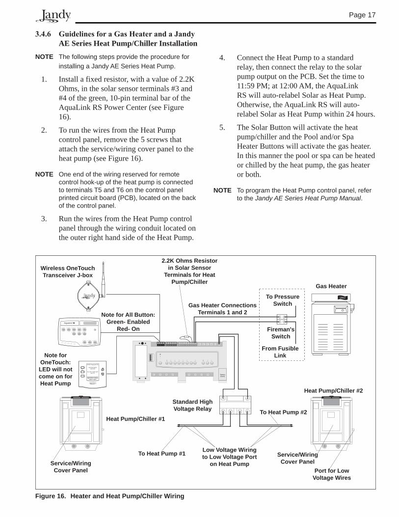
3.4.6 GuidelinesforaGasHeaterandaJandyAE Series Heat Pump/Chiller Installation
NOTE The following steps provide the procedure for installing a Jandy AE Series Heat Pump.
1. Install a fixed resistor, with a value of 2.2K Ohms, in the solar sensor terminals #3 and #4 of the green, 10-pin terminal bar of the AquaLink RS Power Center (see Figure 16).
2. To run the wires from the Heat Pump control panel, remove the 5 screws that attach the service/wiring cover panel to the heat pump (see Figure 16).
NOTE One end of the wiring reserved for remote control hook-up of the heat pump is connected to terminals T5 and T6 on the control panel printed circuit board (PCB), located on the back of the control panel.
3. Run the wires from the Heat Pump control panel through the wiring conduit located on the outer right hand side of the Heat Pump.
4. Connect the Heat Pump to a standard relay, then connect the relay to the solar pump output on the PCB. Set the time to 11:59 PM; at 12:00 AM, the AquaLink RS will auto-relabel Solar as Heat Pump. Otherwise, the AquaLink RS will auto-relabel Solar as Heat Pump within 24 hours.
5. The Solar Button will activate the heat pump/chiller and the Pool and/or Spa Heater Buttons will activate the gas heater. In this manner the pool or spa can be heated or chilled by the heat pump, the gas heater or both.
NOTE To program the Heat Pump control panel, refer to the Jandy AE Series Heat Pump Manual.
4 3 2 1 6 5 4 3 2 1 10 9 8 7 6 5 4 3 2 1
Battery(9Volt)
®
JANDY AquaLink RS
FILTER PUMP OFFAIR 79°
06/26/04 MON6:00 PM
EQUIPMENT ON/OFFONETOUCH ON/OFF
MENU / HELP
Gas heater
heat Pump/Chiller #1
Note for All Button: Green- Enabled
Red- On
Gas heater Connections Terminals 1 and 2
Fireman's Switch
From Fusible link
To Pressure Switch
Note for OneTouch: lED will not come on for heat Pump
2.2K Ohms Resistor in Solar Sensor
Terminals for heat Pump/Chiller
heat Pump/Chiller #2
Figure 16. heater and heat Pump/Chiller Wiring
Service/WiringCover Panel
Service/WiringCover Panel
Port for low Voltage Wires
Standard high Voltage Relay
low Voltage Wiring to low Voltage Port
on heat Pump
To heat Pump #1
To heat Pump #2
Wireless OneTouch Transceiver J-box
Page 18
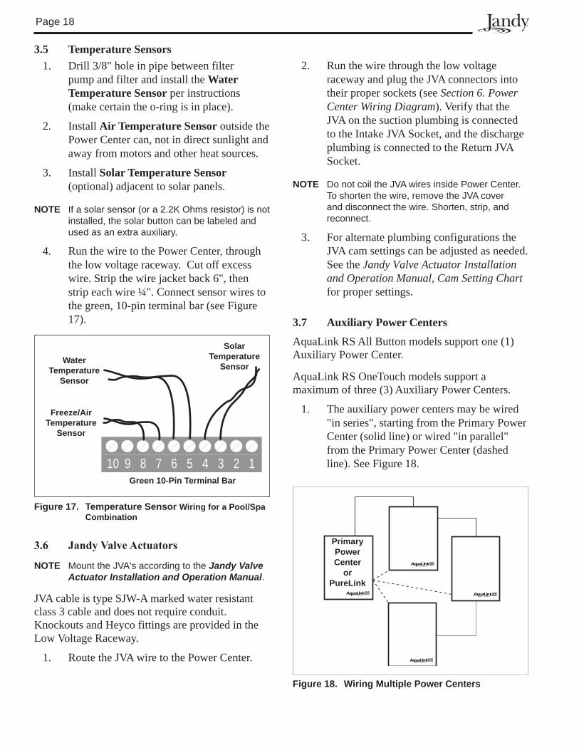
3.5 Temperature Sensors1. Drill 3/8" hole in pipe between filter
pump and filter and install the Water Temperature Sensor per instructions (make certain the o-ring is in place).
2. Install Air Temperature Sensor outside the Power Center can, not in direct sunlight and away from motors and other heat sources.
3. Install Solar Temperature Sensor (optional) adjacent to solar panels.
NOTE If a solar sensor (or a 2.2K Ohms resistor) is not installed, the solar button can be labeled and used as an extra auxiliary.
4. Run the wire to the Power Center, through the low voltage raceway. Cut off excess wire. Strip the wire jacket back 6", then strip each wire ¼". Connect sensor wires to the green, 10-pin terminal bar (see Figure 17).
3.6 JandyValveActuators
NOTE Mount the JVA's according to the Jandy Valve Actuator Installation and Operation Manual.
JVA cable is type SJW-A marked water resistant class 3 cable and does not require conduit. Knockouts and Heyco fittings are provided in the Low Voltage Raceway.
1. Route the JVA wire to the Power Center.
Figure 17. Temperature Sensor Wiring for a Pool/Spa Combination
Water Temperature
Sensor
Freeze/Air Temperature
Sensor
Solar Temperature
Sensor
Green 10-Pin Terminal Bar
10 9 8 7 6 5 4 3 2 1
2. Run the wire through the low voltage raceway and plug the JVA connectors into their proper sockets (see Section 6. Power Center Wiring Diagram). Verify that the JVA on the suction plumbing is connected to the Intake JVA Socket, and the discharge plumbing is connected to the Return JVA Socket.
NOTE Do not coil the JVA wires inside Power Center. To shorten the wire, remove the JVA cover and disconnect the wire. Shorten, strip, and reconnect.
3. For alternate plumbing configurations the JVA cam settings can be adjusted as needed. See the Jandy Valve Actuator Installation and Operation Manual, Cam Setting Chart for proper settings.
3.7 Auxiliary Power Centers
AquaLink RS All Button models support one (1) Auxiliary Power Center.
AquaLink RS OneTouch models support a maximum of three (3) Auxiliary Power Centers.
1. The auxiliary power centers may be wired "in series", starting from the Primary Power Center (solid line) or wired "in parallel" from the Primary Power Center (dashed line). See Figure 18.
PrimaryPower Center
orPurelink
Figure 18. Wiring Multiple Power Centers
Page 19
2. Run four conductor, 22 AWG or larger cable between the red, 4-pin terminal bars in each Power Center.
NOTE • All temperature sensors, heater connections
and the main filter pump must be wired to the Primary Power Center.
• Never put more than two (2) wires into each of the pins of the red, 4-pin terminal bar (use a Jandy Multiplex Board).
• If more than one Auxiliary Power Center is installed, set the jumpers as shown in Figure 19.
Figure 19. Setting Jumpers for Multiple Auxiliary Power Centers
Aux. PC #1(AUX B1 to B8 for RS12, 16,
2/10, 2/14)
W1W2
Aux. PC #2(AUX C1 to
C8 for RS24, 2/22)
Aux. PC #3(AUX D1 to D8 for
RS32, 2/30)
W1 W2
W1W2
(No Jumpers on the Primary Power Center PCB)
3.8 All Button Control Panel Installation
3.8.1 SingleIndoorControlPanel1. With the aid of the homeowner, find the
best location for the Control Panel.
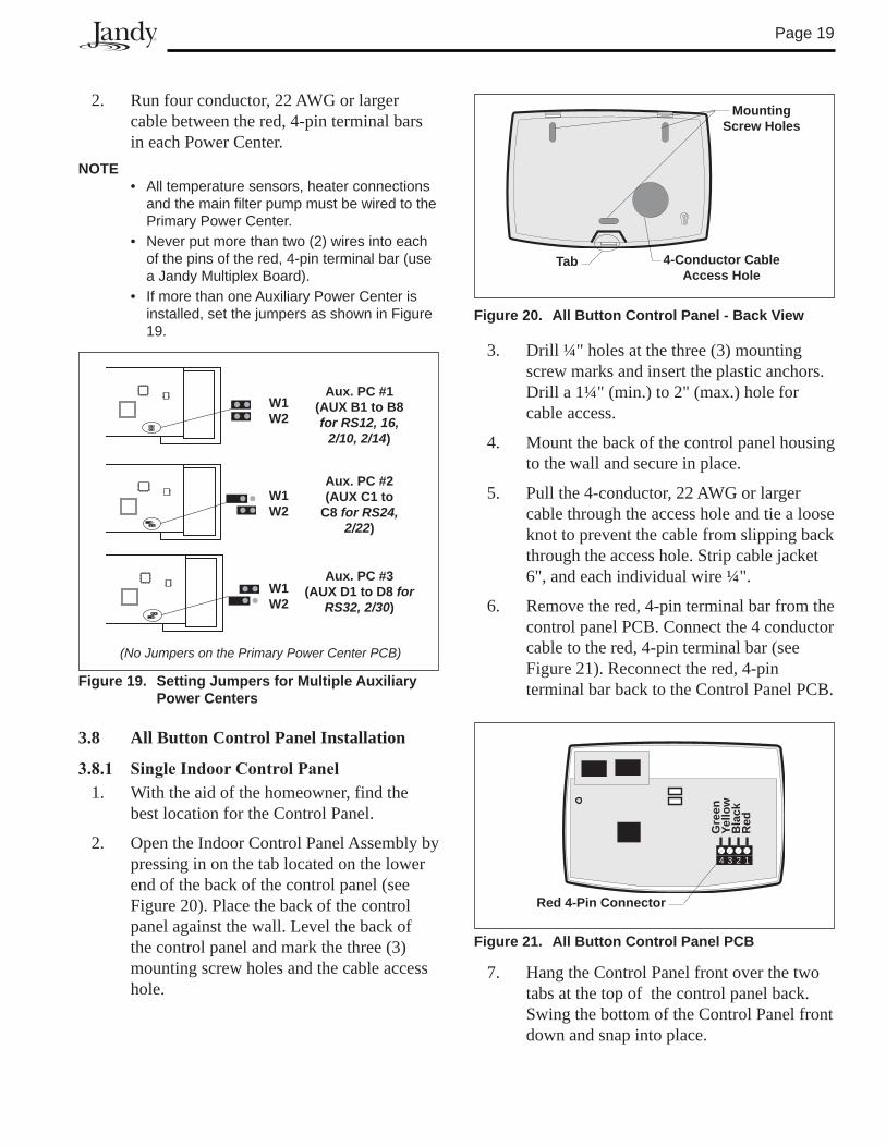
2. Open the Indoor Control Panel Assembly by pressing in on the tab located on the lower end of the back of the control panel (see Figure 20). Place the back of the control panel against the wall. Level the back of the control panel and mark the three (3) mounting screw holes and the cable access hole.
3. Drill ¼" holes at the three (3) mounting screw marks and insert the plastic anchors. Drill a 1¼" (min.) to 2" (max.) hole for cable access.
4. Mount the back of the control panel housing to the wall and secure in place.
5. Pull the 4-conductor, 22 AWG or larger cable through the access hole and tie a loose knot to prevent the cable from slipping back through the access hole. Strip cable jacket 6", and each individual wire ¼".
6. Remove the red, 4-pin terminal bar from the control panel PCB. Connect the 4 conductor cable to the red, 4-pin terminal bar (see Figure 21). Reconnect the red, 4-pin terminal bar back to the Control Panel PCB.
Mounting Screw holes
4-Conductor Cable Access hole
Tab
Figure 20. All Button Control Panel - Back View
Figure 21. All Button Control Panel PCB
4 3 2 1
Red 4-Pin Connector
Gre
enYe
llow
Bla
ckR
ed
7. Hang the Control Panel front over the two tabs at the top of the control panel back. Swing the bottom of the Control Panel front down and snap into place.
Page 20
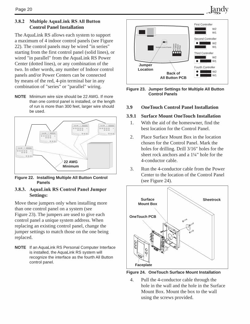
3.8.2 MultipleAquaLinkRSAllButtonControl Panel Installation
The AquaLink RS allows each system to support a maximum of 4 indoor control panels (see Figure 22). The control panels may be wired "in series" starting from the first control panel (solid lines), or wired "in parallel" from the AquaLink RS Power Center (dotted lines), or any combination of the two. In other words, any number of Indoor control panels and/or Power Centers can be connected by means of the red, 4-pin terminal bar in any combination of "series" or "parallel" wiring.
NOTE Minimum wire size should be 22 AWG. If more than one control panel is installed, or the length of run is more than �00 feet, larger wire should be used.
3.8.3. AquaLinkRSControlPanelJumperSettings:
Move these jumpers only when installing more than one control panel on a system (see Figure 23). The jumpers are used to give each control panel a unique system address. When replacing an existing control panel, change the jumper settings to match those on the one being replaced.
NOTE If an AquaLink RS Personal Computer Interface is installed, the AquaLink RS system will recognize the interface as the fourth All Button control panel.
3.9 OneTouch Control Panel Installation
3.9.1 Surface Mount OneTouch Installation 1. With the aid of the homeowner, find the
best location for the Control Panel.
2. Place Surface Mount Box in the location chosen for the Control Panel. Mark the holes for drilling. Drill 3/16" holes for the sheet rock anchors and a 1¼" hole for the 4-conductor cable.
3. Run the 4-conductor cable from the Power Center to the location of the Control Panel (see Figure 24).
W2W1
First Controller
Third Controller
W2W1
Second Controller
W2W1
Fourth Controller
W2W1
Yello
wG
reen
Bla
ckR
ed
W2W1
Multiple Control Panels
Jumper location
Back of All Button PCB
Figure 23. Jumper Settings for Multiple All Button Control Panels
4. Pull the 4-conductor cable through the hole in the wall and the hole in the Surface Mount Box. Mount the box to the wall using the screws provided.
Surface Mount Box
OneTouch PCB
Faceplate
Sheetrock
Figure 24. OneTouch Surface Mount Installation
RS TM
RS TM
RS TM RS TM
Figure 22. Installing Multiple All Button Control Panels
22 AWGMinimum
Page 21
W2W1
4321
GreenYellowBlackRed
Figure 25. OneTouch PCB - Back View
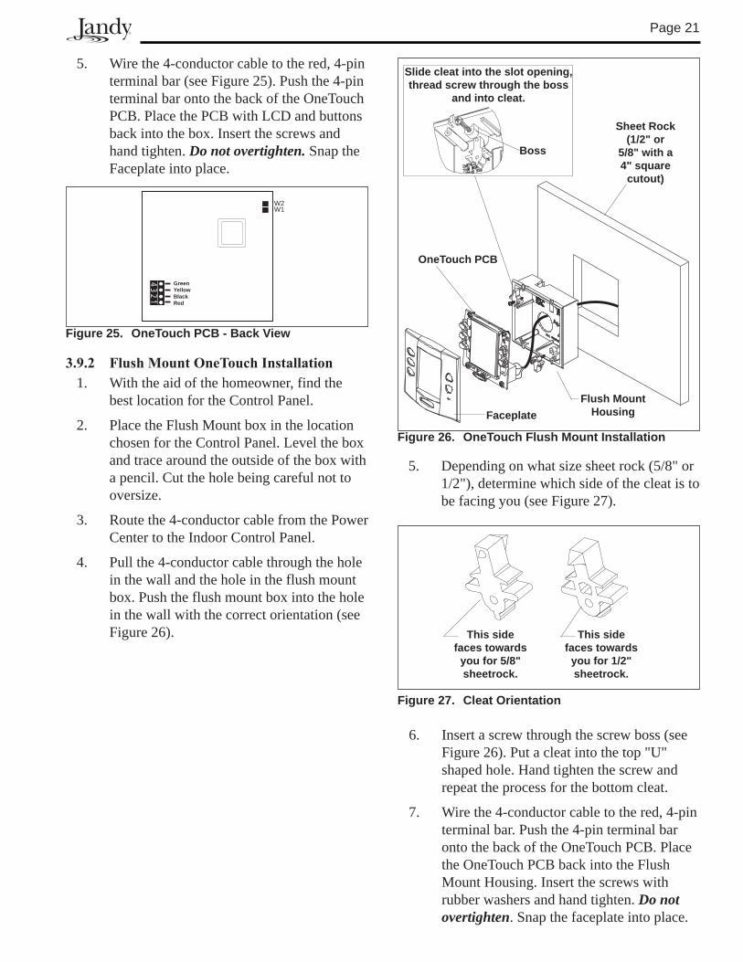
3.9.2 FlushMountOneTouchInstallation1. With the aid of the homeowner, find the
best location for the Control Panel.
2. Place the Flush Mount box in the location chosen for the Control Panel. Level the box and trace around the outside of the box with a pencil. Cut the hole being careful not to oversize.
3. Route the 4-conductor cable from the Power Center to the Indoor Control Panel.
4. Pull the 4-conductor cable through the hole in the wall and the hole in the flush mount box. Push the flush mount box into the hole in the wall with the correct orientation (see Figure 26).
5. Depending on what size sheet rock (5/8" or 1/2"), determine which side of the cleat is to be facing you (see Figure 27).
Figure 27. Cleat Orientation
This side faces towards
you for 5/8" sheetrock.
This side faces towards
you for 1/2" sheetrock.
6. Insert a screw through the screw boss (see Figure 26). Put a cleat into the top "U" shaped hole. Hand tighten the screw and repeat the process for the bottom cleat.
7. Wire the 4-conductor cable to the red, 4-pin terminal bar. Push the 4-pin terminal bar onto the back of the OneTouch PCB. Place the OneTouch PCB back into the Flush Mount Housing. Insert the screws with rubber washers and hand tighten. Do not overtighten. Snap the faceplate into place.
5. Wire the 4-conductor cable to the red, 4-pin terminal bar (see Figure 25). Push the 4-pin terminal bar onto the back of the OneTouch PCB. Place the PCB with LCD and buttons back into the box. Insert the screws and hand tighten. Do not overtighten. Snap the Faceplate into place.
Sheet Rock (1/2" or
5/8" with a 4" square
cutout)
Flush Mount housingFaceplate
OneTouch PCB
Slide cleat into the slot opening, thread screw through the boss
and into cleat.
Boss
Figure 26. OneTouch Flush Mount Installation
Page 22
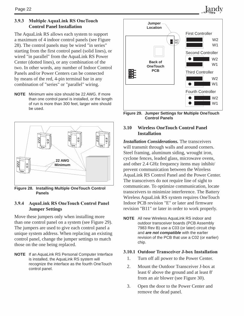
3.9.3 MultipleAquaLinkRSOneTouchControl Panel Installation
The AquaLink RS allows each system to support a maximum of 4 indoor control panels (see Figure 28). The control panels may be wired "in series" starting from the first control panel (solid lines), or wired "in parallel" from the AquaLink RS Power Center (dotted lines), or any combination of the two. In other words, any number of Indoor Control Panels and/or Power Centers can be connected by means of the red, 4-pin terminal bar in any combination of "series" or "parallel" wiring.
NOTE Minimum wire size should be 22 AWG. If more than one control panel is installed, or the length of run is more than �00 feet, larger wire should be used.
3.9.4 AquaLinkRSOneTouchControlPanelJumper Settings
Move these jumpers only when installing more than one control panel on a system (see Figure 29). The jumpers are used to give each control panel a unique system address. When replacing an existing control panel, change the jumper settings to match those on the one being replaced.
NOTE If an AquaLink RS Personal Computer Interface is installed, the AquaLink RS system will recognize the interface as the fourth OneTouch control panel.
3.10 Wireless OneTouch Control Panel Installation
Installation Considerations. The transceivers will transmit through walls and around corners. Steel framing, aluminum siding, wrought iron, cyclone fences, leaded glass, microwave ovens, and other 2.4 GHz frequency items may inhibit/prevent communication between the Wireless AquaLink RS Control Panel and the Power Center. The transceivers do not require line of sight to communicate. To optimize communication, locate transceivers to minimize interference. The Battery Wireless AquaLink RS system requires OneTouch Indoor PCB revision "E" or later and firmware revision "B11" or later in order to work properly.
NOTE All new Wireless AquaLink RS indoor and outdoor transceiver boards (PCB Assembly �98� Rev B) use a C0� (or later) circuit chip and are not compatible with the earlier revision of the PCB that use a C02 (or earlier) chip.
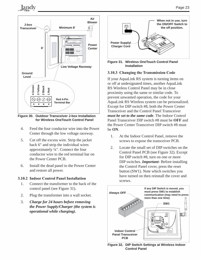
3.10.1 OutdoorTransceiverJ-boxInstallation1. Turn off all power to the Power Center.
2. Mount the Outdoor Transceiver J-box at least 6' above the ground and at least 8' from an air blower (see Figure 30).
3. Open the door to the Power Center and remove the dead panel.
Back of OneTouch
PCB
Figure 29. Jumper Settings for Multiple OneTouch Control Panels
Jumper location
W2W1
4321
W2W1
First Controller
Third Controller
W2W1
Second Controller
W2W1
Fourth Controller
W2W1
Figure 28. Installing Multiple OneTouch Control Panels
22 AWGMinimum
Page 2�
4. Feed the four conductor wire into the Power Center through the low voltage raceway.
5. Cut off the excess wire. Strip the jacket back 6" and strip the individual wires approximately ¼". Connect the four conductor wire to the red terminal bar on the Power Center PCB.
6. Install the dead panel to the Power Center and restore all power.
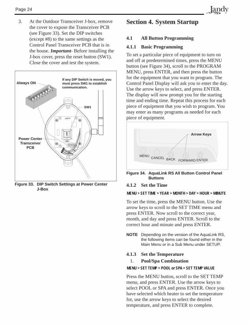
3.10.2 IndoorControlPanelInstallation1. Connect the transformer to the back of the
control panel (see Figure 31).
2. Plug the transformer into a wall socket.
3. Charge for 24 hours before removing the Power Supply/Charger (the system is operational while charging).
J-box Transceiver
6'
low Voltage Raceway
Minimum 8'
Air Blower
Power Center
Ground level
3 Ye
llow
1 R
ed
2 B
lack
4 G
reen
Red 4-Pin Terminal Bar
Figure 30. Outdoor Transceiver J-box Installation for Wireless OneTouch Control Panel
When not in use, turn the ON/OFF Switch to
the off position.
Power Supply/Charger Cord
Figure 31. Wireless OneTouch Control Panel Installation
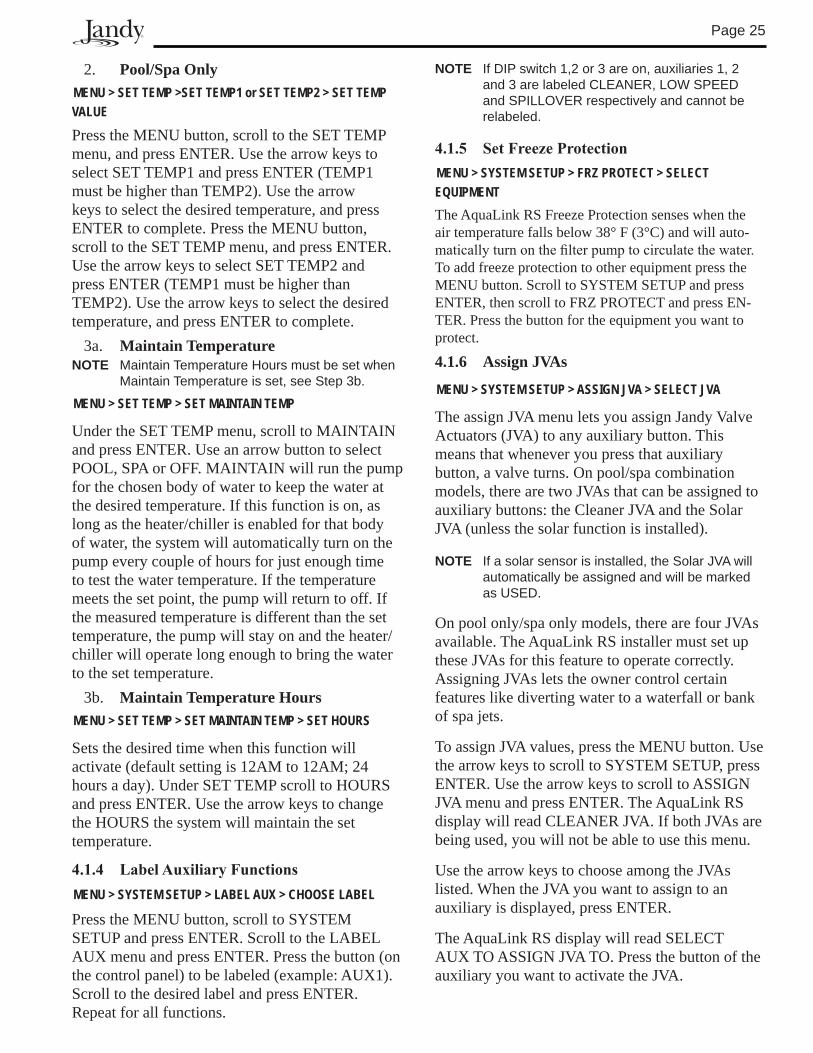
3.10.3 ChangingtheTransmissionCodeIf your AquaLink RS system is turning items on or off at undesignated times, another AquaLink RS Wireless Control Panel may be in close proximity using the same or similar code. To prevent unwanted operation, the code for your AquaLink RS Wireless system can be personalized. Except for DIP switch #8, both the Power Center Transceiver and the Control Panel Transceiver must be set to the same code. The Indoor Control Panel Transceiver DIP switch #8 must be OFF and the Power Center Transceiver DIP switch #8 must be ON.
1. At the Indoor Control Panel, remove the screws to expose the transceiver PCB.
2. Locate the small set of DIP switches on the Control Panel PCB (see Figure 32). Except for DIP switch #8, turn on one or more DIP switches. Important- Before installing the Control Panel cover, press the reset button (SW1). Note which switches you have turned on then reinstall the cover and screws.
ON
12
34
56
78
Always OFFIf any DIP Switch is moved, you must press SW1 to establish communication (may need to press more than one time).
SW1
Indoor Control Panel Transceiver
PCB
Figure 32. DIP Switch Settings at Wireless Indoor Control Panel
Page 24
3. At the Outdoor Transceiver J-box, remove the cover to expose the Transceiver PCB (see Figure 33). Set the DIP switches (except #8) to the same settings as the Control Panel Transceiver PCB that is in the house. Important- Before installing the J-box cover, press the reset button (SW1). Close the cover and test the system.
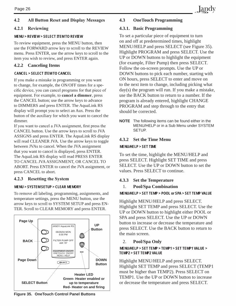
Section 4. System Startup
4.1 All Button Programming
4.1.1 Basic ProgrammingTo set a particular piece of equipment to turn on and off at predetermined times, press the MENU button (see Figure 34), scroll to the PROGRAM MENU, press ENTER, and then press the button for the equipment that you want to program. The Control Panel Display will ask you to enter the day. Use the arrow keys to select, and press ENTER. The display will now prompt you for the starting time and ending time. Repeat this process for each piece of equipment that you wish to program. You may enter as many programs as needed for each piece of equipment.
4.1.2 Set the TimeMENU > SET TIME > YEAR > MONTH > DAY > HOUR > MINUTE
To set the time, press the MENU button. Use the arrow keys to scroll to the SET TIME menu and press ENTER. Now scroll to the correct year, month, and day and press ENTER. Scroll to the correct hour and minute and press ENTER.
NOTE Depending on the version of the AquaLink RS, the following items can be found either in the Main Menu or in a Sub Menu under SETUP.
4.1.3 Set the Temperature 1. Pool/Spa Combination
MENU > SET TEMP > POOL or SPA > SET TEMP VALUE
Press the MENU button, scroll to the SET TEMP menu, and press ENTER. Use the arrow keys to select POOL or SPA and press ENTER. Once you have selected which heater to set the temperature for, use the arrow keys to select the desired temperature, and press ENTER to complete.
Figure 33. DIP Switch Settings at Power Center J-Box
ON
12
34
56
78
Always ONIf any DIP Switch is moved, you must press SW1 to establish communication.
SW1
Power CenterTransceiver
PCB
Figure 34. Aqualink RS All Button Control Panel Buttons
MENUCANCEL BACK FORWARD ENTER
Arrow Keys
Page 25
2. Pool/Spa OnlyMENU > SET TEMP >SET TEMP1 or SET TEMP2 > SET TEMP VALUE
Press the MENU button, scroll to the SET TEMP menu, and press ENTER. Use the arrow keys to select SET TEMP1 and press ENTER (TEMP1 must be higher than TEMP2). Use the arrow keys to select the desired temperature, and press ENTER to complete. Press the MENU button, scroll to the SET TEMP menu, and press ENTER. Use the arrow keys to select SET TEMP2 and press ENTER (TEMP1 must be higher than TEMP2). Use the arrow keys to select the desired temperature, and press ENTER to complete.
3a. Maintain TemperatureNOTE Maintain Temperature Hours must be set when
Maintain Temperature is set, see Step �b.
MENU > SET TEMP > SET MAINTAIN TEMP
Under the SET TEMP menu, scroll to MAINTAIN and press ENTER. Use an arrow button to select POOL, SPA or OFF. MAINTAIN will run the pump for the chosen body of water to keep the water at the desired temperature. If this function is on, as long as the heater/chiller is enabled for that body of water, the system will automatically turn on the pump every couple of hours for just enough time to test the water temperature. If the temperature meets the set point, the pump will return to off. If the measured temperature is different than the set temperature, the pump will stay on and the heater/chiller will operate long enough to bring the water to the set temperature.
3b. Maintain Temperature HoursMENU > SET TEMP > SET MAINTAIN TEMP > SET HOURS
Sets the desired time when this function will activate (default setting is 12AM to 12AM; 24 hours a day). Under SET TEMP scroll to HOURS and press ENTER. Use the arrow keys to change the HOURS the system will maintain the set temperature.
4.1.4 LabelAuxiliaryFunctionsMENU > SYSTEM SETUP > LABEL AUX > CHOOSE LABEL
Press the MENU button, scroll to SYSTEM SETUP and press ENTER. Scroll to the LABEL AUX menu and press ENTER. Press the button (on the control panel) to be labeled (example: AUX1). Scroll to the desired label and press ENTER. Repeat for all functions.
NOTE If DIP switch 1,2 or � are on, auxiliaries 1, 2 and � are labeled CLEANER, LOW SPEED and SPILLOVER respectively and cannot be relabeled.
4.1.5 SetFreezeProtectionMENU > SYSTEM SETUP > FRZ PROTECT > SELECT EQUIPMENTThe AquaLink RS Freeze Protection senses when the air temperature falls below 38° F (3°C) and will auto-maticallyturnonthefilterpumptocirculatethewater.To add freeze protection to other equipment press the MENU button. Scroll to SYSTEM SETUP and press ENTER, then scroll to FRZ PROTECT and press EN-TER. Press the button for the equipment you want to protect.
4.1.6 Assign JVAs
MENU > SYSTEM SETUP > ASSIGN JVA > SELECT JVA
The assign JVA menu lets you assign Jandy Valve Actuators (JVA) to any auxiliary button. This means that whenever you press that auxiliary button, a valve turns. On pool/spa combination models, there are two JVAs that can be assigned to auxiliary buttons: the Cleaner JVA and the Solar JVA (unless the solar function is installed).
NOTE If a solar sensor is installed, the Solar JVA will automatically be assigned and will be marked as USED.
On pool only/spa only models, there are four JVAs available. The AquaLink RS installer must set up these JVAs for this feature to operate correctly. Assigning JVAs lets the owner control certain features like diverting water to a waterfall or bank of spa jets.
To assign JVA values, press the MENU button. Use the arrow keys to scroll to SYSTEM SETUP, press ENTER. Use the arrow keys to scroll to ASSIGN JVA menu and press ENTER. The AquaLink RS display will read CLEANER JVA. If both JVAs are being used, you will not be able to use this menu.
Use the arrow keys to choose among the JVAs listed. When the JVA you want to assign to an auxiliary is displayed, press ENTER.
The AquaLink RS display will read SELECT AUX TO ASSIGN JVA TO. Press the button of the auxiliary you want to activate the JVA.
Page 26
4.2 AllButtonResetandDisplayMessages
4.2.1 Reviewing
MENU > REVIEW > SELECT ITEM TO REVIEWTo review equipment, press the MENU button, then use the FORWARD arrow key to scroll to the REVIEW menu. Press ENTER, use the arrow keys to scroll to the item you wish to review, and press ENTER again.
4.2.2 Canceling Items
CANCEL > SELECT ITEM TO CANCEL If you make a mistake in programming or you want to change, for example, the ON/OFF times for a spe-cificdevice,youcancancelprogramsforthatpieceofequipment. For example, to canceladimmer, press the CANCEL button; use the arrow keys to advance to DIMMERS and press ENTER. The AquaLink RS display will prompt you to select an Aux. Press the button of the auxiliary for which you want to cancel the dimmer.IfyouwanttocancelaJVAassignment,firstpresstheCANCEL button. Use the arrow keys to scroll to JVA ASSIGNS and press ENTER. The AquaLink RS display will read CLEANER JVA. Use the arrow keys to toggle between JVAs to cancel. When the JVA assignment that you want to cancel is displayed, press ENTER. The AquaLink RS display will read PRESS ENTER TO CANCEL JVA ASSIGNMENT, OR CANCEL TO ABORT. Press ENTER to cancel the JVA assignment, or press CANCEL to abort.
4.2.3 ResettingtheSystem
MENU > SYSTEM SETUP > CLEAR MEMORYTo remove all labeling, programming, assignments, and temperature settings, press the MENU button, use the arrow keys to scroll to SYSTEM SETUP and press EN-TER. Scroll to CLEAR MEMORY and press ENTER.
4.3 OneTouch Programming
4.3.1. Basic ProgrammingTo set a particular piece of equipment to turn on and off at predetermined times, highlight MENU/HELP and press SELECT (see Figure 35). Highlight PROGRAM and press SELECT. Use the UP or DOWN buttons to highlight the equipment (for example, Filter Pump) then press SELECT. Follow the on-screen prompts. Use the UP or DOWN buttons to pick each number, starting with ON hours, press SELECT to enter and move on to the next item to change, including picking what day(s) the program will run. If you make a mistake, use the BACK button to return to a number. If the program is already entered, highlight CHANGE PROGRAM and step through to the entry that should be corrected.
NOTE The following items can be found either in the MENU/HELP or in a Sub Menu under SYSTEM SETUP.
4.3.2 Set the Time MenuMENU/HELP > SET TIME
To set the time, highlight the MENU/HELP and press SELECT. Highlight SET TIME and press SELECT. Use the UP or DOWN button to set the values. Press SELECT to continue.
4.3.3 Set the Temperature 1. Pool/Spa Combination
MENU/HELP > SET TEMP > POOL or SPA > SET TEMP VALUE
Highlight MENU/HELP and press SELECT. Highlight SET TEMP and press SELECT. Use the UP or DOWN button to highlight either POOL or SPA and press SELECT. Use the UP or DOWN button to increase or decrease the temperature and press SELECT. Use the BACK button to return to the main screen.
2. Pool/Spa OnlyMENU/HELP > SET TEMP > TEMP1 > SET TEMP1 VALUE > TEMP2 > SET TEMP2 VALUE
Highlight MENU/HELP and press SELECT. Highlight SET TEMP and press SELECT (TEMP1 must be higher than TEMP2). Press SELECT on TEMP1. Use the UP or DOWN button to increase or decrease the temperature and press SELECT.
JANDY AquaLink RS
FILTER PUMP OFFAIR 79°
06/26/04 MON6:00 PM
EQUIPMENT ON/OFFONETOUCH ON/OFF
MENU / HELP
UP Button
DOWN Button
SElECT Button
Page Up
BACK
Page Down
heater lEDGreen- heater enabled or
up to temperatureRed- heater on and firing
Figure 35. OneTouch Control Panel Buttons
Page 2�
NOTE The Auxiliary labels AIR BLOWER and FILL LINE have an automatic �0 minute runtime. To change this setting, refer to the DEVICE RUNTIME feature. If DIP switch 1,2 or � are on, auxiliaries 1, 2 and � are labeled CLEANER, LOW SPEED and SPILLOVER respectively and cannot be relabeled.
4.3.5 SetFreezeProtectionMENU/HELP > SYSTEM SETUP > FREEZE PROTECT > SET TEMP VALUE > SELECT FREEZE PROTECT DEVICE
Highlight MENU/HELP and press SELECT. Highlight SYSTEM SETUP and press SELECT. Highlight FREEZE PROTECT and press SELECT. Use the UP or DOWN button to change the temperature. Once the temperature is set press the SELECT button to move to the next screen to assign freeze protection to a selected piece of equipment. Highlight a device and press SELECT. "X" means the device has been assigned.
NOTE The filter pump is always assigned to freeze protection.
4.3.6 Assign JVAsMENU/HELP > SYSTEM SETUP > ASSIGN JVAs > SELECT JVAHighlight MENU/HELP and press SELECT. Highlight SYSTEM SETUP and press SELECT. Highlight AS-SIGN JVA and press SELECT. Highlight the JVA you wish to assign and press SELECT. NOTE If a solar sensor is installed, the Solar JVA will
automatically be assigned and will be marked as USED.
4.4 OneTouchResetandDisplayMessages
4.4.1 RestartingtheSystemMENU/HELP > SYSTEM SETUP > CLEAR MEMORY > CONTINUE > FINAL WARNING > CONTINUETo remove all labeling, programming, assignments and temperature settings, highlight MENU/HELP and press SELECT. Highlight SYSTEM SETUP and press SELECT. Highlight CLEAR MEMORY and press SELECT. Highlight CONTINUE and press SELECT. Use the UP or DOWN button to highlight YES or NO and press SELECT. There will be about a 15 second delay before you see the FINISHED screen. Highlight CONTINUE and press SELECT to return to the SYSTEM SETUP.
Highlight TEMP2 and press SELECT (TEMP1 must be higher than TEMP2). Use the UP or DOWN button to increase or decrease the temperature and press SELECT. Use the BACK button to return to the main screen.
3. Maintain Temperature MENU/HELP > SET TEMP >MAINTAIN
In the SET TEMP menu, highlighting MAINTAIN and pressing SELECT will turn on (or off) the MAINTAIN function. MAINTAIN will run the pump for the chosen body of water to keep the water at the desired temperature. If this function is on, as long as the heater/chiller is enabled for that body of water, the system will automatically turn on the pump every couple of hours for just enough time to test the water temperature. If the temperature meets the set point, the pump will return to off. If the measured temperature is different than the set temperature, the pump will stay on and the heater/chiller will operate long enough to bring the water to the set temperature.
4. Maintain Temperature HoursMENU/HELP > SET TEMP >HOURS
Sets the desired time when this function will activate (default setting is 12AM to 12AM; 24 hours a day). Highlight HOURS and press SELECT. Use the UP or DOWN buttons to change the HOURS the system will maintain the set temperature.
4.3.4 LabelAuxiliaryFunctionsMENU/HELP > SYSTEM SETUP > LABEL AUX > AUX 1-X > CHOOSE LABEL TYPE > CHOOSE LABEL
Highlight MENU/HELP and press SELECT. Highlight SYSTEM SETUP and press SELECT. Highlight LABEL AUX and press SELECT. Highlight the AUX you want to label and press SELECT. Highlight GENERAL, LIGHT, WATERFALL or CUSTOM LABEL and press SELECT. Choose a name within these categories by using the UP or DOWN button or the PAGE UP or PAGE DOWN button, press SELECT when you find the correct name. Choose CUSTOM to type in your own names.
Page 28
4.5 AllButtonandOneTouchSystemDefaultsandGeneralModes
CAUTIONIn service mode, the safety interlocks for equipment protection are overridden.
Default Temperature (Pool/Spa Combination) Default Pool Temp = 80° FDefault Spa Temp = 102° F
Default Temperature (Pool/Spa Only) Default TEMP1 = 80° FDefault TEMP2 = 60° F
Default Spa Side Switch Settings Button 1 = Spa (Filter Pump for pool/spa only models)Button 2 = Spa Heater (Temp1 for pool/spa only models)Button � = AUX1Button 4 = AUX2
Default Freeze Protection Settings FILTER PUMP: freeze protection ON. ALL OTHER EQUIPMENT, freeze protection OFF.
NOTE If you select SPA to be freeze protected, water circulation will switch between pool and spa every �0 minutes during freezing conditions once freeze mode is active.
4.5.1 Power Center Service Switch
AUTOMode(automatic)1. The control panel has complete control of all
functions. 2. All programmed settings will operate. 3. All safety delays and equipment protection
interlocks are operational.
SERVICEMode1. The power center has complete control of all
functions. 2. Service mode must be turned on/off at the
power center. 3. No programmed settings will work.
TIMEOUTMode1. The power center has complete control for
three (3) hours. 2. After three (3) hours the system will return to
AUTO mode. 3. Programmed on/off times will be overridden
during the three (3) hours.4. After the three (3) hour "time out", the system
will resume any programmed items that were overridden.
4.5.2 ChangingtheChlorineProductionSettings at the Equipment
The AquaPure and AquaLink RS now have two-way communication. The AquaLink RS Power Center will read settings or modifications made from the AquaPure Service Panel. This feature is available with AquaPure front PCB firmware version 11230A05 or later. Your firmware revision number can be found on the back of the front AquaPure PCB.
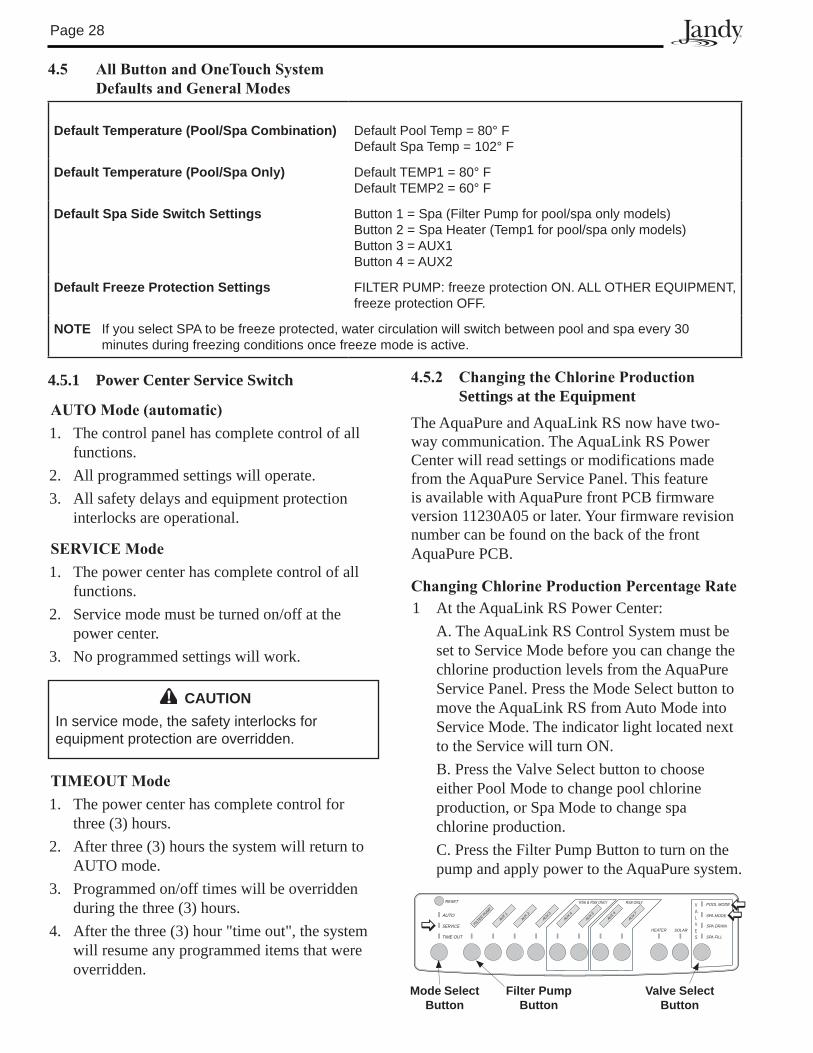
ChangingChlorineProductionPercentageRate1 At the AquaLink RS Power Center: A. The AquaLink RS Control System must be
set to Service Mode before you can change the chlorine production levels from the AquaPure Service Panel. Press the Mode Select button to move the AquaLink RS from Auto Mode into Service Mode. The indicator light located next to the Service will turn ON.
B. Press the Valve Select button to choose either Pool Mode to change pool chlorine production, or Spa Mode to change spa chlorine production.
C. Press the Filter Pump Button to turn on the pump and apply power to the AquaPure system.
Mode Select Button
Valve Select Button
Filter Pump Button
RESET
AUTO
SERVICE
TIME OUT
FILTER PUMP
AUX 1AUX 2
AUX 3AUX 4
AUX 5AUX 6
AUX 7
RS6 & RS8 ONLY RS8 ONLY
HEATER SOLAR
POOL MODE
SPA MODE
SPA DRAIN
SPA FILL
Page 29
ATTENTIONSpecial Note to Startup Person: The AquaLink RS allows two (2) options for operating the pool equipment on the first day of operation:Option #1 - Once all programming of equipment is completed, the AquaLink RS will automatically review all programs and turn on any equipment which is programmed to be on. Option #2 - To operate the filter pump or cleaner continually for the first day, leave the power center service button in AUTO mode. At the indoor control panel, press the filter pump or cleaner buttons for the equipment you want to run. The equipment that is activated will run continuously, ignoring the first programmed off time, and will turn off at the programmed off time for the next day (only if a program has been entered).
4.5.3 Battery Backup
A nine-volt battery is located at the power center. The battery keeps the clock running during a power outage so the time and date will be correct when power is restored. Programming will not be lost even if the battery is dead. Do not install the battery in the power center until the system is ready to operate. Battery will drain if power is left off. Review DIAGNOSTICS in the SYSTEM SETUP section of the menu. The DIAGNOSTICS will indicate when the battery needs replacement.
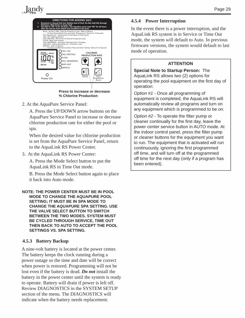
1. Broadcast or Spread Salt into Shallow End of Pool. Do Not Add Salt throughSkimmers, Main Drain or Surge Tank.
2. Set Unit to "00" % for 24 Hours. The AquaPure must read "00" for 24 hours after the salt has been added and circulated in the pool.
Boost - 24 Hour 100% Chlorine Production Cycle - Refer to Manual- - - - To Enter Boost Mode Press and Hold "Temperature" Button for 10 SecondsPool Temperature - Temperature of Pool Water at Flow SensorCELL ON - Making ChlorineCELL RESTING - Off Portion of Chlorine Production CycleFLOW - Water Flow PresentCELL REVERSING - Automatic Cleaning Cycle in ProgressADD SALT - Salinity Should be 3.0 - 3.5 Grams / LiterSERVICE - Refer to Manual -- - - - To Silence Audible Service Alarm Press and Hold "Salinity" Button for 5 Seconds
DIRECTIONS FOR ADDING SALT
Power On
CELL ON
CELL RESTING
FLOW
CELL REVERSING
ADD SALT
SERVICE
CHLORINEPRODUCTION RATE
C D
A B
? ?Salinity Pool
Temperature- Boost -
Press to increase or decrease % Chlorine Production
2. At the AquaPure Service Panel: A. Press the UP/DOWN arrow buttons on the
AquaPure Service Panel to increase or decrease chlorine production rate for either the pool or spa.
When the desired value for chlorine production is set from the AquaPure Service Panel, return to the AquaLink RS Power Center.
3. At the AquaLink RS Power Center: A. Press the Mode Select button to put the
AquaLink RS in Time Out mode. B. Press the Mode Select button again to place
it back into Auto mode.
NOTE: ThE POWER CENTER MUST BE IN POOl MODE TO ChANGE ThE AqUAPURE POOl SETTING; IT MUST BE IN SPA MODE TO ChANGE ThE AqUAPURE SPA SETTING. USE ThE VAlVE SElECT BUTTON TO SWITCh BETWEEN ThE TWO MODES. SYSTEM MUST BE CYClED ThROUGh SERVICE, TIME OUT ThEN BACK TO AUTO TO ACCEPT ThE POOl SETTINGS VS. SPA SETTING.
4.5.4 Power InterruptionIn the event there is a power interruption, and the AquaLink RS system is in Service or Time Out mode, the system will default to Auto. In previous firmware versions, the system would default to last mode of operation.
Page �0
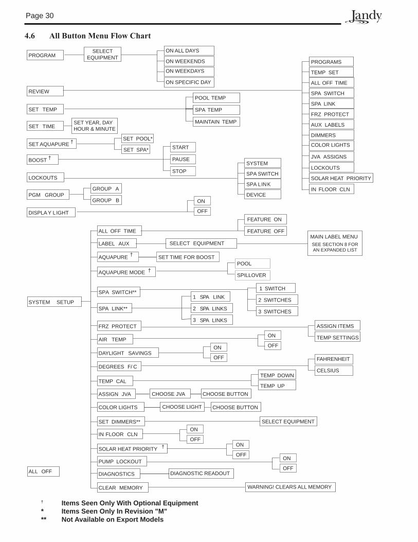
4.6 AllButtonMenuFlowChart
† Items Seen Only With Optional Equipment * Items Seen Only In Revision "M" ** Not Available on Export Models
REVIEW
PROGRAMSELECT
EQUIPMENTON ALL DAYS
SET TEMP
POOL TEMP
SPA TEMP
SET TIMESET YEAR, DAYHOUR & MINUTE
LOCKOUTS
SYSTEM
SPA SWITCH
SPA LINK
DEVICEPGM GROUPGROUP A
GROUP B
DISPLA Y LIGHT
PROGRAMS
TEMP SET
SPA SWITCH
SPA LINK
FRZ PROTECT
AUX LABELS
DIMMERS
JVA ASSIGNS
LOCKOUTS
ALL OFF TIME
SET POOL*
MAINTAIN TEMP
SYSTEM SETUP
ALL OFF TIME
ASSIGN JVA
TEMP CAL
DEGREES F/ C
AIR TEMP
FRZ PROTECT
SPA LINK**
SPA SWITCH**
MAIN LABEL MENUSEE SECTION 8 FORAN EXPANDED LIST
SET DIMMERS**
SELECT EQUIPMENT
ALL OFF
LABEL AUX
AQUAPURE †
DAYLIGHT SAVINGS
DIAGNOSTICS
IN FLOOR CLN
SOLAR HEAT PRIORITY
PUMP LOCKOUT
SET TIME FOR BOOST
FEATURE ON
FEATURE OFF
3 SWITCHES
2 SWITCHES
1 SWITCH
3 LINKS
2 LINKS
1 SPA LINK
TEMP SETTINGS
ASSIGN ITEMS
DIAGNOSTIC READOUT
CLEAR MEMORY WARNING! CLEARS ALL MEMORY
CHOOSE JVATEMP UP
TEMP DOWNCELSIUS
FAHRENHEIT
SELECT EQUIPMENT
OFF
ON
SOLAR HEAT PRIORITY
IN FLOOR CLN
COLOR LIGHTS
SET AQUAPURE † COLOR LIGHTS
AQUAPURE MODE †POOL
SPILLOVER
SPA
SPA
BOOST †
START
PAUSE
STOP
†OFF
ON
OFF
ON
OFF
ON OFF
ON
OFF
ON
CHOOSE LIGHT
CHOOSE BUTTON
CHOOSE BUTTON
ON WEEKENDS
ON WEEKDAYS
ON SPECIFIC DAY
SET SPA*
Page �1
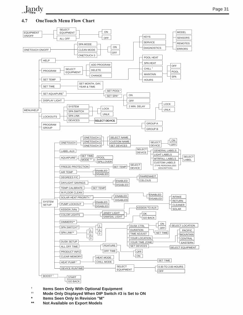
4.7 OneTouchMenuFlowChart
ONETOUCH ON/OFF
SPA MODE
CLEAN MODE
ONETOUCH 3
ON
OFF
MENU/HELP
PROGRAM
SET TEMP
POOL HEAT
SPA HEAT
SET TIMESET MONTH, DAY,YEAR & TIME
DISPLAY LIGHT
ON
OFF
2 MIN. DELAY
LOCKOUTS
SYSTEM
SPA SWITCH
SPA LINK
DEVICES
LOCK
UNLK
SELECT DEVICESELECT DEVICE
LOCK
UNLK
PROGRAMGROUP
GROUP A
GROUP B
SYSTEMSETUP
LABEL AUX
TEMP CALIBRATE
IN FLOOR CLEAN
SOLAR HEAT PRIORITY †
ASSIGN JVAs
DIMMERS**
SPA SWITCH**
SPA LINK**
PRODUCT INFO
CLEAR MEMORY
ONETOUCH
ONETOUCH 1ONETOUCH 2ONETOUCH 3
SELECT NAMECUSTOM NAMESET DEVICES
ONOFF
GENERAL LABELSLIGHT LABELSWTRFALL LABELS
(TYPE PERSONALIZEDDESCRIPTION)
INTAKERETURNCLEANERSOLAR
123
123
OKGO BACK
ENABLEDDISABLED
ENABLEDDISABLED
SET TEMP
FREEZE PROTECTION
AIR TEMP
DEGREES F/C
ENABLEDDISABLED
FAHRENHEITCELCIUS
SET TEMP
DAYLIGHT SAVINGSENABLEDDISABLED
PUMP LOCKOUTENABLEDDISABLED
DUSK SETUP
DUSK CTRLDURATIONTIME ADJUST
YOUR LOCATIONYOUR TIME ZONESET DEVICES
SELECT LOCATION
PACIFICMOUNTAINCENTRALEASTERN
SELECT EQUIPMENT
BOOST †
SET AQUAPURE†SET POOL*
AQUAPURE† SET TIME
MAINTAIN
HOURS
HELP
KEYS
SERVICE
DIAGNOSTICS
OFF
SPA
POOL
STARTGO BACK
ONOFF
SET TIME
ALL OFF TIME FEATURE
OFF TIME OFF
ON
SET TIME
EQUIPMENT ON/OFF
SELECT EQUIPMENT ON
OFFALL OFF
ADD PROGRAM
DELETE
CHANGE
CHILL †
MODEL
SENSORS
REMOTES
ERRORS
MODE ††POOL
SPILLOVER
COLOR LIGHTSJANDY LIGHTSAM/SAL LIGHT
ASSIGN TO AUX
DEVICE RUNTIMESELECTEQUIPMENT
0:30 TO 2:00 HOURS
OFF
HEAT PUMP †HEAT MODE
CHILL MODE
SELECT EQUIPMENT
SELECTDEVICE
SELECTDEVICE
SELECTDEVICE
SELECTLABEL
CUSTOM LABELS
SET SPA*
† Items Seen Only With Optional Equipment †† Mode Only Displayed When DIP Switch #3 is Set to ON * Items Seen Only In Revision "M" ** Not Available on Export Models
Page �2
Section 5. Troubleshooting
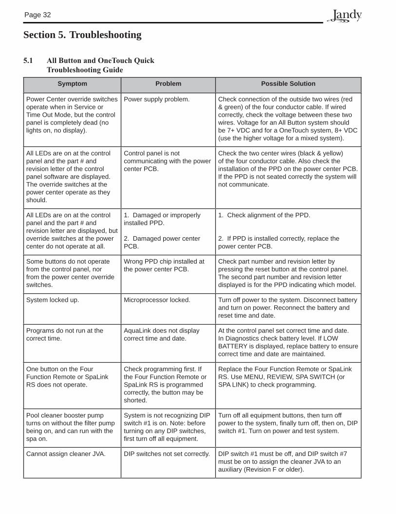
5.1 AllButtonandOneTouchQuick TroubleshootingGuide
Symptom Problem Possible Solution
Power Center override switches operate when in Service or Time Out Mode, but the control panel is completely dead (no lights on, no display).
Power supply problem. Check connection of the outside two wires (red & green) of the four conductor cable. If wired correctly, check the voltage between these two wires. Voltage for an All Button system should be �+ VDC and for a OneTouch system, 8+ VDC (use the higher voltage for a mixed system).
All LEDs are on at the control panel and the part # and revision letter of the control panel software are displayed. The override switches at the power center operate as they should.
Control panel is not communicating with the power center PCB.
Check the two center wires (black & yellow) of the four conductor cable. Also check the installation of the PPD on the power center PCB. If the PPD is not seated correctly the system will not communicate.
All LEDs are on at the control panel and the part # and revision letter are displayed, but override switches at the power center do not operate at all.
1. Damaged or improperly installed PPD.
2. Damaged power center PCB.
1. Check alignment of the PPD.
2. If PPD is installed correctly, replace the power center PCB.
Some buttons do not operate from the control panel, nor from the power center override switches.
Wrong PPD chip installed at the power center PCB.
Check part number and revision letter by pressing the reset button at the control panel. The second part number and revision letter displayed is for the PPD indicating which model.
System locked up. Microprocessor locked. Turn off power to the system. Disconnect battery and turn on power. Reconnect the battery and reset time and date.
Programs do not run at the correct time.
AquaLink does not display correct time and date.
At the control panel set correct time and date. In Diagnostics check battery level. If LOW BATTERY is displayed, replace battery to ensure correct time and date are maintained.
One button on the Four Function Remote or SpaLink RS does not operate.
Check programming first. If the Four Function Remote or SpaLink RS is programmed correctly, the button may be shorted.
Replace the Four Function Remote or SpaLink RS. Use MENU, REVIEW, SPA SWITCH (or SPA LINK) to check programming.
Pool cleaner booster pump turns on without the filter pump being on, and can run with the spa on.
System is not recognizing DIP switch #1 is on. Note: before turning on any DIP switches, first turn off all equipment.
Turn off all equipment buttons, then turn off power to the system, finally turn off, then on, DIP switch #1. Turn on power and test system.
Cannot assign cleaner JVA. DIP switches not set correctly. DIP switch #1 must be off, and DIP switch #� must be on to assign the cleaner JVA to an auxiliary (Revision F or older).
Page ��
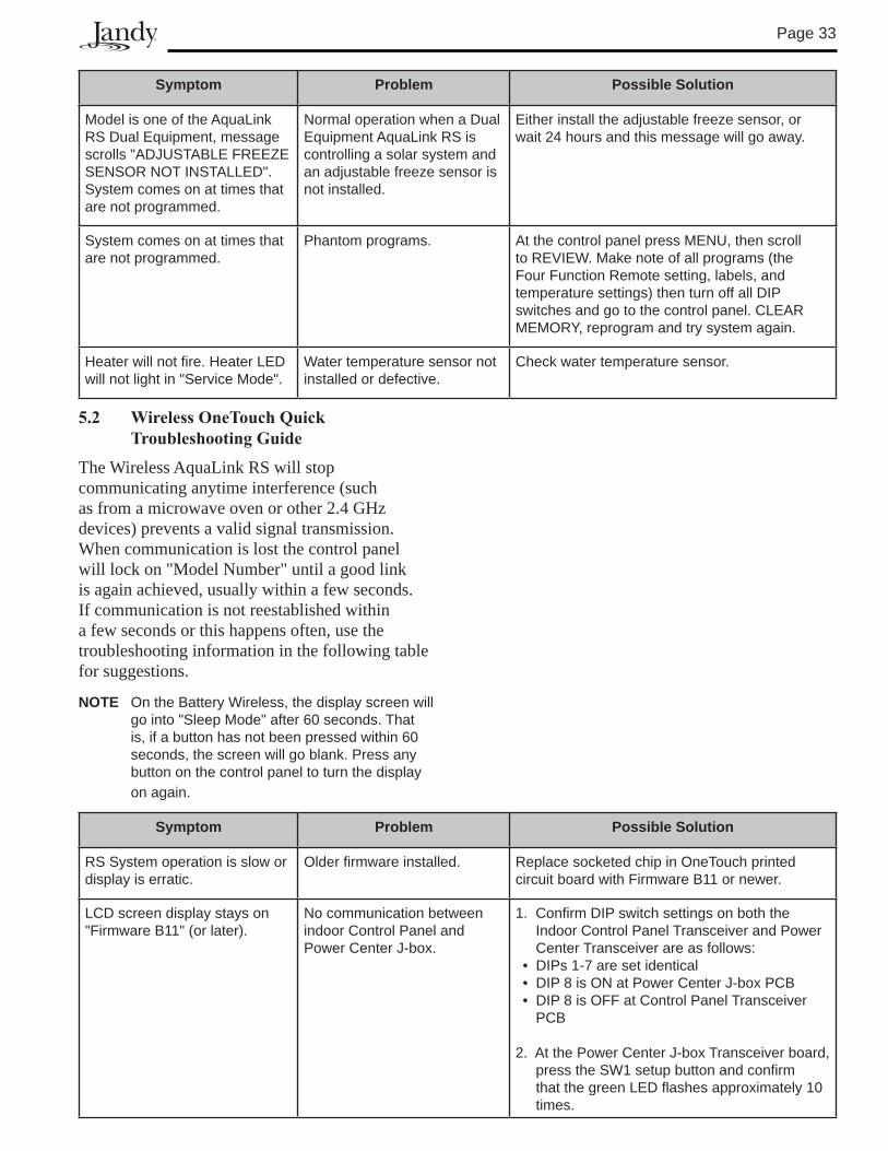
Symptom Problem Possible Solution
Model is one of the AquaLink RS Dual Equipment, message scrolls "ADJUSTABLE FREEZE SENSOR NOT INSTALLED".System comes on at times that are not programmed.
Normal operation when a Dual Equipment AquaLink RS is controlling a solar system and an adjustable freeze sensor is not installed.
Either install the adjustable freeze sensor, or wait 24 hours and this message will go away.
System comes on at times that are not programmed.
Phantom programs. At the control panel press MENU, then scroll to REVIEW. Make note of all programs (the Four Function Remote setting, labels, and temperature settings) then turn off all DIP switches and go to the control panel. CLEAR MEMORY, reprogram and try system again.
Heater will not fire. Heater LED will not light in "Service Mode".
Water temperature sensor not installed or defective.
Check water temperature sensor.
5.2 WirelessOneTouchQuickTroubleshootingGuide
The Wireless AquaLink RS will stop communicating anytime interference (such as from a microwave oven or other 2.4 GHz devices) prevents a valid signal transmission. When communication is lost the control panel will lock on "Model Number" until a good link is again achieved, usually within a few seconds. If communication is not reestablished within a few seconds or this happens often, use the troubleshooting information in the following table for suggestions.
NOTE On the Battery Wireless, the display screen will go into "Sleep Mode" after 60 seconds. That is, if a button has not been pressed within 60 seconds, the screen will go blank. Press any button on the control panel to turn the display on again.
Symptom Problem Possible Solution
RS System operation is slow or display is erratic.
Older firmware installed. Replace socketed chip in OneTouch printed circuit board with Firmware B11 or newer.
LCD screen display stays on "Firmware B11" (or later).
No communication between indoor Control Panel and Power Center J-box.
1. Confirm DIP switch settings on both the Indoor Control Panel Transceiver and Power Center Transceiver are as follows:
• DIPs 1-� are set identical• DIP 8 is ON at Power Center J-box PCB• DIP 8 is OFF at Control Panel Transceiver
PCB
2. At the Power Center J-box Transceiver board, press the SW1 setup button and confirm that the green LED flashes approximately 10 times.
Page �4
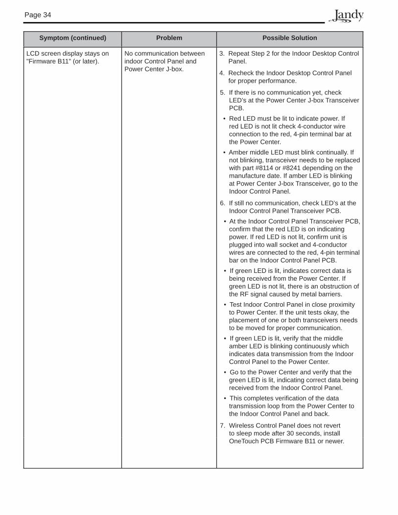
Symptom (continued) Problem Possible Solution
LCD screen display stays on "Firmware B11" (or later).
No communication between indoor Control Panel and Power Center J-box.
�. Repeat Step 2 for the Indoor Desktop Control Panel.
4. Recheck the Indoor Desktop Control Panel for proper performance.
5. If there is no communication yet, check LED’s at the Power Center J-box Transceiver PCB.
• Red LED must be lit to indicate power. If red LED is not lit check 4-conductor wire connection to the red, 4-pin terminal bar at the Power Center.
• Amber middle LED must blink continually. If not blinking, transceiver needs to be replaced with part #8114 or #8241 depending on the manufacture date. If amber LED is blinking at Power Center J-box Transceiver, go to the Indoor Control Panel.
6. If still no communication, check LED’s at the Indoor Control Panel Transceiver PCB.
• At the Indoor Control Panel Transceiver PCB, confirm that the red LED is on indicating power. If red LED is not lit, confirm unit is plugged into wall socket and 4-conductor wires are connected to the red, 4-pin terminal bar on the Indoor Control Panel PCB.
• If green LED is lit, indicates correct data is being received from the Power Center. If green LED is not lit, there is an obstruction of the RF signal caused by metal barriers.
• Test Indoor Control Panel in close proximity to Power Center. If the unit tests okay, the placement of one or both transceivers needs to be moved for proper communication.
• If green LED is lit, verify that the middle amber LED is blinking continuously which indicates data transmission from the Indoor Control Panel to the Power Center.
• Go to the Power Center and verify that the green LED is lit, indicating correct data being received from the Indoor Control Panel.
• This completes verification of the data transmission loop from the Power Center to the Indoor Control Panel and back.
�. Wireless Control Panel does not revert to sleep mode after �0 seconds, install OneTouch PCB Firmware B11 or newer.
Page �5
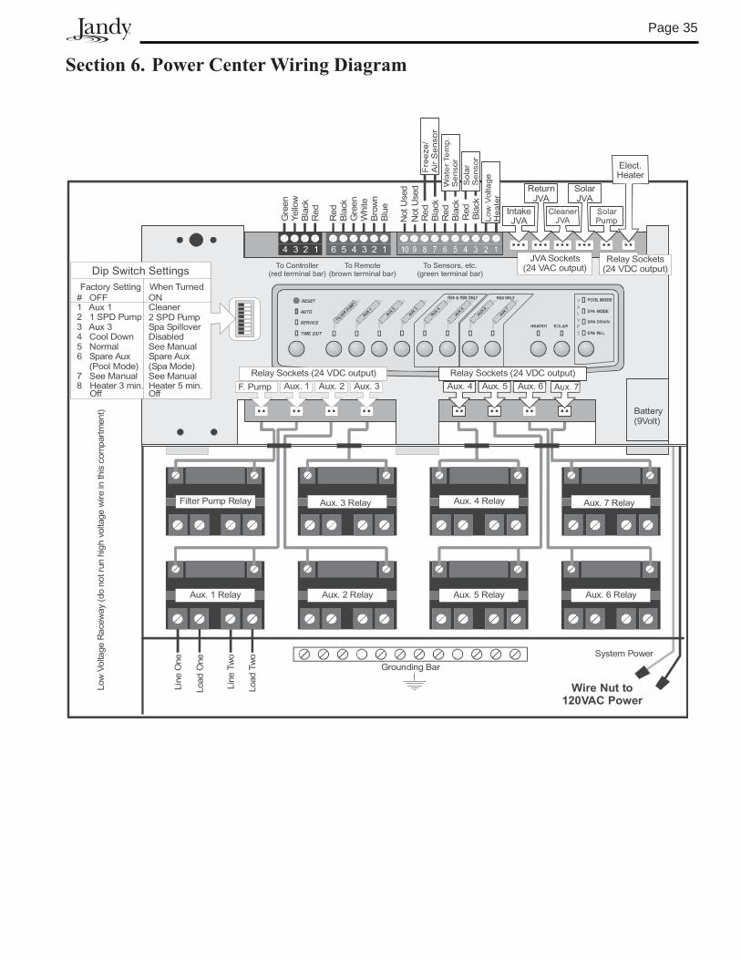
Section6.PowerCenterWiringDiagram
Aux. 4 Relay Aux. 7 Relay
Aux. 5 Relay Aux. 6 Relay
Filter Pump Relay Aux. 3 Relay
Aux. 1 Relay
Line
One
Low
Volta
geR
acew
ay(d
ono
trun
high
volta
gew
irein
this
com
part
men
t)
Line
Two
Load
One
Load
Two
Aux. 2 Relay
Grounding Bar
Wire Nut to120VAC Power
System Power
IntakeJVA
CleanerJVA
SolarPump
ReturnJVA
SolarJVA
Elect.Heater
Red
Bla
ckG
reen
Whi
te
Yello
wG
reen
Bla
ckR
ed
Bro
wn
To Remote(brown terminal bar)
To Sensors, etc.(green terminal bar)
To Controller(red terminal bar)
4 3 2 1 6 5 4 3 2 1
Blu
e
Red
Bla
ckR
edB
lack
F. Pump Aux. 2 Aux. 3 Aux. 6Aux. 5Aux. 4
Relay Sockets(24 VDC output)
JVA Sockets(24 VAC output)
# OFF1 Aux 12 1 SPD Pump3 Aux 34 Cool Down5 Normal6 Spare Aux
(Pool Mode)7 See Manual8 Heater 3 min.
Off
Battery(9Volt)
Dip Switch SettingsFactory Setting
ONCleaner2 SPD PumpSpa SpilloverDisabledSee ManualSpare Aux(Spa Mode)See Manual
Red
Bla
ck
Not
Use
dN
otU
sed
FILTER
PUMP
AUX1
AUX
2
AUX
3
AUX4
AUX
5
AUX6
AUX
7
Relay Sockets (24 VDC output) Relay Sockets (24 VDC output)
When Turned
Heater 5 min.Off
Aux 1.
Page �6
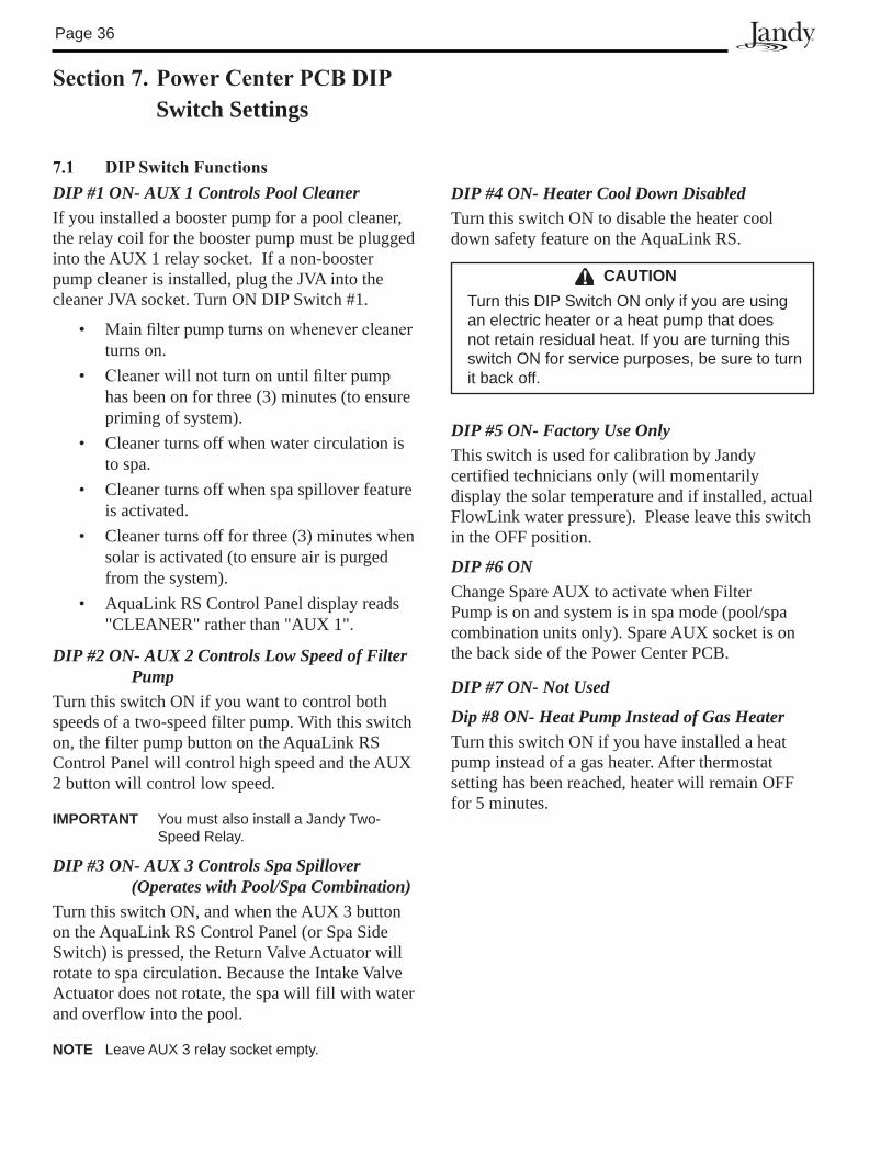
Section7.PowerCenterPCBDIPSwitch Settings
7.1 DIPSwitchFunctionsDIP #1 ON- AUX 1 Controls Pool CleanerIf you installed a booster pump for a pool cleaner, the relay coil for the booster pump must be plugged into the AUX 1 relay socket. If a non-booster pump cleaner is installed, plug the JVA into the cleaner JVA socket. Turn ON DIP Switch #1.
• Mainfilterpumpturnsonwhenevercleanerturns on.
• Cleanerwillnotturnonuntilfilterpumphas been on for three (3) minutes (to ensure priming of system).
• Cleaner turns off when water circulation is to spa.
• Cleaner turns off when spa spillover feature is activated.
• Cleaner turns off for three (3) minutes when solar is activated (to ensure air is purged from the system).
• AquaLink RS Control Panel display reads "CLEANER" rather than "AUX 1".
DIP #2 ON- AUX 2 Controls Low Speed of Filter Pump
Turn this switch ON if you want to control both speeds of a two-speed filter pump. With this switch on, the filter pump button on the AquaLink RS Control Panel will control high speed and the AUX 2 button will control low speed.
IMPORTANT You must also install a Jandy Two- Speed Relay.
DIP #3 ON- AUX 3 Controls Spa Spillover (Operates with Pool/Spa Combination)
Turn this switch ON, and when the AUX 3 button on the AquaLink RS Control Panel (or Spa Side Switch) is pressed, the Return Valve Actuator will rotate to spa circulation. Because the Intake Valve Actuator does not rotate, the spa will fill with water and overflow into the pool.
NOTE Leave AUX � relay socket empty.
CAUTIONTurn this DIP Switch ON only if you are using an electric heater or a heat pump that does not retain residual heat. If you are turning this switch ON for service purposes, be sure to turn it back off.
DIP #4 ON- Heater Cool Down DisabledTurn this switch ON to disable the heater cool down safety feature on the AquaLink RS.
DIP #5 ON- Factory Use OnlyThis switch is used for calibration by Jandy certified technicians only (will momentarily display the solar temperature and if installed, actual FlowLink water pressure). Please leave this switch in the OFF position.
DIP #6 ONChange Spare AUX to activate when Filter Pump is on and system is in spa mode (pool/spa combination units only). Spare AUX socket is on the back side of the Power Center PCB.
DIP #7 ON- Not Used
Dip #8 ON- Heat Pump Instead of Gas HeaterTurn this switch ON if you have installed a heat pump instead of a gas heater. After thermostat setting has been reached, heater will remain OFF for 5 minutes.
Page ��
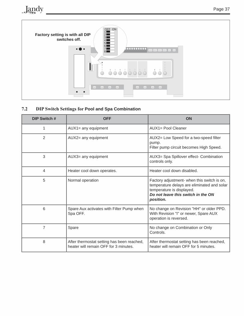
7.2 DIPSwitchSettingsforPool and Spa Combination
DIP Switch # OFF ON
1 AUX1= any equipment AUX1= Pool Cleaner
2 AUX2= any equipment AUX2= Low Speed for a two-speed filter pump.Filter pump circuit becomes High Speed.
� AUX�= any equipment AUX�= Spa Spillover effect- Combination controls only.
4 Heater cool down operates. Heater cool down disabled.
5 Normal operation Factory adjustment- when this switch is on, temperature delays are eliminated and solar temperature is displayed. Do not leave this switch in the ON position.
6 Spare Aux activates with Filter Pump when Spa OFF.
No change on Revision "HH" or older PPD. With Revision "I" or newer, Spare AUX operation is reversed.
� Spare No change on Combination or Only Controls.
8 After thermostat setting has been reached, heater will remain OFF for � minutes.
After thermostat setting has been reached, heater will remain OFF for 5 minutes.
Factory setting is with all DIP switches off.
1OFF ON
345678
2
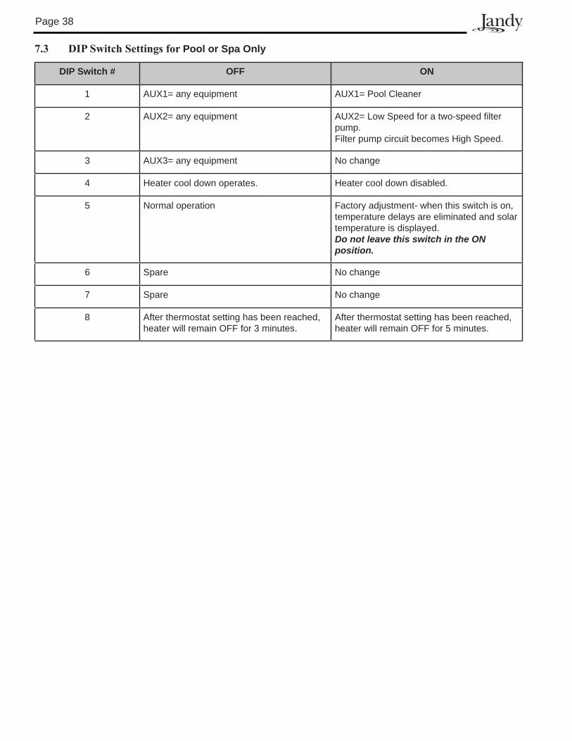
Page �8
7.3 DIPSwitchSettingsforPool or Spa Only
DIP Switch # OFF ON
1 AUX1= any equipment AUX1= Pool Cleaner
2 AUX2= any equipment AUX2= Low Speed for a two-speed filter pump.Filter pump circuit becomes High Speed.
� AUX�= any equipment No change
4 Heater cool down operates. Heater cool down disabled.
5 Normal operation Factory adjustment- when this switch is on, temperature delays are eliminated and solar temperature is displayed. Do not leave this switch in the ON position.
6 Spare No change
� Spare No change
8 After thermostat setting has been reached, heater will remain OFF for � minutes.
After thermostat setting has been reached, heater will remain OFF for 5 minutes.
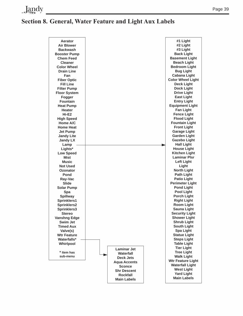
Page �9
Section8.General,WaterFeatureandLightAuxLabels
AeratorAir BlowerBackwash
Booster PumpChem Feed
CleanerColor WheelDrain line
FanFiber Optic
Fill lineFilter Pump
Floor SystemFogger
Fountainheat Pump
heater hi-E2
high Speedhome A/Chome heatJet PumpJandy liteJandy lX
lamplights*
low SpeedMist
MusicNot UsedOzonator
PondRay-Vac
SlideSolar Pump
SpaSpillway
Sprinklers1Sprinklers2Sprinklers3
StereoVanshng Edge
Swim JetTimed Aux
Valve(s)Wtr FeatureWaterfalls*Whirlpool
* Item hassub-menu
#1 light #2 light#3 light
Back lightBasement light
Beach lightBedroom light
Bug lightCabana light
Color Wheel lightDeck lightDock lightDrive lightEast lightEntry light
Equipment lightFan light
Fence lightFlood light
Fountain lightFront light
Garage lightGarden lightGazebo light
hall lighthouse light
Kitchen lightlaminar Plsr
left lightlight
North lightPath lightPatio light
Perimeter lightPond lightPool light
Porch lightRight lightRoom lightSauna light
Security lightShower lightShrub lightSouth lightSpa light
Statue lightSteps lightTable lightTier lightTree lightWalk light
Wtr Feature lightWaterfall light
West lightYard light
Main labels
laminar JetWaterfallDeck Jets
Aqua AccentsSconce
Shr DescentRockfall
Main labels

LIMITED WARRANTYThank you for purchasing Jandy® pool and spa products. Jandy Pool Products, Inc. warrants all parts to be freefrom manufacturing defects in materials and workmanship for a period of one year from the date of retail purchase, with the following exceptions:
• AquaLink® RS units installed with Jandy Surge Protection Kits will be covered for two years.• NeverLube® valves are warranted for the life of pool and/or spa on which they were originally installed.• AquaPureTM Electronic Chlorine Generator Electrolytic Cells carry a 5 year limited warranty on a prorated basis.
This warranty is limited to the first retail purchaser, is not transferable, and does not apply to products that have been moved from their original installation sites. The liability of Jandy Pool Products, Inc. shall not exceed the repair or replacement of defective parts and does not include any costs for labor to remove and reinstall the defective part, transportation to or from the factory, and any other materials required to make the repair. This warranty does not cover failures or malfunctions resulting from the following:
1. Failure to properly install, operate or maintain the product(s) in accordance with our published Installation,Operation and Maintenance Manuals provided with the product(s).
2. The workmanship of any installer of the product(s).3. Not maintaining a proper chemical balance in your pool and/or spa [pH level between 7.2 and 7.8, Total
Alkalinity (TA) between 80 to 120 ppm, Total Dissolved Solids (TDS) less than 2000 not including salt ppm].4. Abuse, alteration, accident, fire, flood, lightning, rodents, insects, negligence or acts of God.5. Scaling, freezing, or other conditions causing inadequate water circulation.6. Operating the product(s) at water flow rates outside the published minimum and maximum specifications.7. Use of non-factory authorized parts or accessories in conjunction with the product(s).8. Chemical contamination of combustion air or improper use of sanitizing chemicals, such as introducing
sanitizing chemicals upstream of the heater and cleaner hose or through the skimmer.9. Overheating; incorrect wire runs; improper electrical supply; collateral damage caused by failure of O-Rings,
DE grids, or cartridge elements; or damage caused by running the pump with insufficient quantities of water.
LIMITATION OF LIABILITY:This is the only warranty given by Jandy Pool Products, Inc. No one is authorized to make any other warranties on behalf of Jandy Pool Products, Inc. THIS WARRANTY IS IN LIEU OF ALL OTHER WARRANTIES, EXPRESSED OR IMPLIED, INCLUDING BUT NOT LIMITED TO ANY IMPLIED WARRANTIES OF FITNESS FOR A PARTICULAR PURPOSE AND MERCHANTABILITY. JANDY POOL PRODUCTS, INC. EXPRESSLY DISCLAIMS AND EXCLUDES ANY LIABILITY FOR CONSEQUENTIAL, INCIDENTAL, INDIRECT OR PUNITIVE DAMAGES FOR BREACH OF ANY EXPRESSED OR IMPLIED WARRANTY. This warranty gives you specific legal rights. You may also have other rights which vary by state or province.
WARRANTY CLAIMS:For prompt warranty consideration, contact your dealer and provide the following information: proof of purchase, model number, serial number and date of installation. The installer will contact the factory for instructions regarding the claim and to determine the location of the nearest designated service center. If the dealer is not available, you can locate a service center in your area by visiting www.jandy.com or by calling our technical support department at (707) 776-8200 extension 260. All returned parts must have a Returned Material Authorization number to be evaluated under the terms of this warranty.
6000 Condor Drive • Moorpark, CA USA 93021 • 707.776.8200 • Fax 707.763.7785Jandy Pool Products, Inc.
She
et #
6594
, Rev
. K
Litho in U.S.A. © 2006 Jandy Pool Products, Inc. 0601
For technical support call �0�-��6-8200, ext. 260


![Plain-paper digital Fax/Copier/Printer/Scanner ... · Overview of the Character Entry Screen [All Clear] button Press this to delete all characters. [Clear] button Press this to delete](https://img.pdfslide.us/doc/110x75/5fd5792535c0a455a51f07d4/plain-paper-digital-faxcopierprinterscanner-overview-of-the-character-entry.jpg)