Embed Size (px)
Citation preview
P/NO : MFL68019901
INSTALLATION MANUAL
AIR CONDITIONER • Please read this installation manual completely before installing the product.• Installation work must be performed in accordance with the national wiring standards by authorized personnel only.• Please retain this installation manual for future reference after reading it thoroughly.
TYPE : WALL MOUNTED
http://www.lghvac.comwww.lg.com
ENGLIS
HFRANÇAIS
ESPAÑOL

FLEX MULTI SPLIT INSTALLATION INSTRUCTIONS
Installation Manual 3
Multi Air Conditioner Installation Manual
TABLE OF CONTENTS
Installation Parts Provided ...................................................4
Product Introduction .............................................................4
Indoor Unit.........................................................................4
Outdoor Unit ......................................................................4
Safety Precautions ................................................................5
Installation of Indoor, Outdoor Unit .....................................8
Select the best location ....................................................8
Installation ..............................................................................9
Preparing work for Installation...........................................9
Sticking the installation guide map and fixing Indoor unit.....10
Drill a hole in the wall ......................................................10
Installation of Wired Remote Controller(Optional) ...........11
Flaring Work and Connection of Piping ............................13
Flaring work.....................................................................13
Connection of piping - Indoor ..........................................14
Connecting the Cable between Indoor Unit and
Outdoor Unit.........................................................................17
Connect the cable to the Indoor unit ...............................17
Checking the Drainage, Forming the Pipings and Long
Pipe Setting ..........................................................................20
Checking the drainage ....................................................20
Panel Front Assembly .........................................................21
o Level gaugeo Screw drivero Electric drillo Hole core drill (ø50mm)
o Flaring tool seto Specified torque wrenches
1.8kg.m, 4.2kg.m, 5.5kg.m, 6.6kg.m (different depending on model No.)
o Adjustable wrench
oA glass of watero Screw driver
o Hexagonal wrench(4mm)o Refrigerant Gas Leak Detectoro Vacuum pumpo Gauge manifold
o Owner's manualo Thermometero Remote Control Holder
Installation Requirements Required Tools
ENGLIS
H

4 Multi Air Conditioner
Installation Parts Provided
Product Introduction
Signal receiver
Front Panel
Air Discharge
Air Filter
ON/OFF button
Air outlet vents
Base plate
Connection pipeDrain hose
Connecting wire
Air intake vents
Indoor Unit
Outdoor Unit
h The figure can be changed according to model.
Installation Parts Provided
Type "A" screw and plastic anchor
Type "B" screw Remote control holder
Installation guide map
Installation Parts

Installation Manual 5
Safety Precautions ENGLIS
H
To prevent the injury of the user or other people and property damage, the following instructionsmust be followed.n Be sure to read before installing the air conditioner.n Be sure to observe the cautions specified here as they include important items related to safety.n Incorrect operation due to ignoring instruction will cause harm or damage. The seriousness is
classified by the following indications.
n The meanings of the symbols used in this manual are as shown below.
WARNING
CAUTION
This symbol indicates the possibility of death or serious injury.
This symbol indicates the possibility of injury or damage to properties only.
WARNINGn Installation
Be sure not to do.
Be sure to follow the instruction.
Safety Precautions
Always perform grounding.
• Otherwise, it may cause electri-cal shock.
Donʼt use a power cable, aplug or a loose socket whichis damaged.
• Otherwise, it may cause a fire orelectrical shock.
For installation of the product,always contact the service cen-ter or a professional installationagency.
• Otherwise, it may cause a fire,electrical shock, explosion or in-jury.
Securely attach the electricalpart cover to the indoor unitand the service panel to theoutdoor unit.
• If the electrical part cover of theindoor unit and the service panelof the outdoor unit are not at-tached securely, it could result ina fire or electric shock due todust, water, etc.
Always install an air leakagebreaker and a dedicatedswitching board.
• No installation may cause a fireand electrical shock.
Do not keep or use flammablegases or combustibles nearthe air conditioner.
• Otherwise, it may cause a fire orthe failure of product.
Ensure that an installation frame of the out-door unit is not damaged due to use for a longtime.
• It may cause injury or an accident.
Do not disassemble or repair the product ran-domly.
• It will cause a fire or electrical shock.
6 Multi Air Conditioner
Safety Precautions
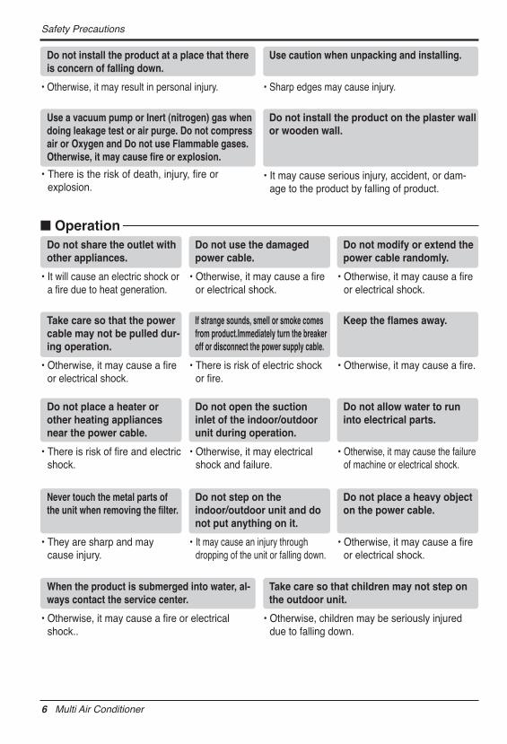
Do not install the product at a place that thereis concern of falling down.
• Otherwise, it may result in personal injury.
Use caution when unpacking and installing.
• Sharp edges may cause injury.
Use a vacuum pump or Inert (nitrogen) gas whendoing leakage test or air purge. Do not compressair or Oxygen and Do not use Flammable gases.Otherwise, it may cause fire or explosion.
• There is the risk of death, injury, fire orexplosion.
Do not install the product on the plaster wallor wooden wall.
• It may cause serious injury, accident, or dam-age to the product by falling of product.
Do not place a heater orother heating appliancesnear the power cable.
• There is risk of fire and electricshock.
Do not open the suctioninlet of the indoor/outdoorunit during operation.
• Otherwise, it may electricalshock and failure.
Do not allow water to runinto electrical parts.
• Otherwise, it may cause the failureof machine or electrical shock.
Never touch the metal parts ofthe unit when removing the filter.
• They are sharp and maycause injury.
Do not step on theindoor/outdoor unit and donot put anything on it.
• It may cause an injury throughdropping of the unit or falling down.
Do not place a heavy objecton the power cable.
• Otherwise, it may cause a fireor electrical shock.
When the product is submerged into water, al-ways contact the service center.
• Otherwise, it may cause a fire or electricalshock..
Take care so that children may not step onthe outdoor unit.
• Otherwise, children may be seriously injureddue to falling down.
Do not share the outlet withother appliances.
• It will cause an electric shock ora fire due to heat generation.
Do not use the damagedpower cable.
• Otherwise, it may cause a fireor electrical shock.
Do not modify or extend thepower cable randomly.
• Otherwise, it may cause a fireor electrical shock.
Take care so that the powercable may not be pulled dur-ing operation.
• Otherwise, it may cause a fireor electrical shock.
If strange sounds, smell or smoke comesfrom product.Immediately turn the breakeroff or disconnect the power supply cable.
• There is risk of electric shockor fire.
Keep the flames away.
• Otherwise, it may cause a fire.
n Operation

Installation Manual 7
Safety Precautions ENGLIS
H
CAUTIONn Installation
Install the drain hose to ensure that draincan be securely done.
• Otherwise, it may cause water leakage.
Install the product so that the noise or hotwind from the outdoor unit may not causeany damage to the neighbors.
• Otherwise, it may cause dispute with the neigh-bors.
Always inspect gas leakage after the instal-lation and repair of product.
• Otherwise, it may cause the failure of product.
Keep level parallel in installing the product.
• Otherwise, it may cause vibration or water leak-age.
Avoid excessive cooling and perform venti-lation sometimes.
• Otherwise, it may do harm to your health.
Use a soft cloth to clean. Do not use wax,thinner, or a strong detergent.
• The appearance of the air conditioner may de-teriorate, change color, or develop surfaceflaws.
Do not use an appliance for special purposessuch as preserving animals vegetables, preci-sion machine, or art articles.
• Otherwise, it may damage your properties.
Do not place obstacles around the flow inletor outlet.
• Otherwise, it may cause the failure of applianceor an accident.
n Operation
8 Multi Air Conditioner
Installation of Indoor, Outdoor Unit
Installation of Indoor, Outdoor UnitRead completely, then follow step by step.
Select the best location
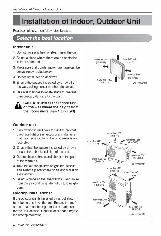
Indoor unit1. Do not have any heat or steam near the unit.
2. Select a place where there are no obstaclesin front of the unit.
3. Make sure that condensation drainage can beconveniently routed away.
4. Do not install near a doorway.
5. Ensure the spaces indicated by arrows fromthe wall, ceiling, fence or other obstacles.
6. Use a stud finder to locate studs to preventunnecessary damage to the wall.
Outdoor unit1. If an awning is built over the unit to prevent
direct sunlight or rain exposure, make surethat heat radiation from the condenser is notrestricted.
2. Ensure that the spaces indicated by arrowsaround front, back and side of the unit.
3. Do not place animals and plants in the pathof the warm air.
4. Take the air conditioner weight into accountand select a place where noise and vibrationare minimum.
5. Select a place so that the warm air and noisefrom the air conditioner do not disturb neigh-bors.
Rooftop Installations:If the outdoor unit is installed on a roof struc-ture, be sure to level the unit. Ensure the roofstructure and anchoring method are adequatefor the unit location. Consult local codes regard-ing rooftop mounting.
Unit : mm(inch)
more than 200 (7-7/8)
more than 500 (19-11/16)
more than 1500 (59-1/16)
more than 500 (19-11/16)
more than 700 (27-9/16)
more than 300 (11-13/16)
more than 300 (11-13/16)
more than 300 (11-13/16)more than 300
(11-13/16)
more than 600 (23-21/32)
more than 600 (23-21/32)
Unit : mm(inch)
Unit : mm(inch)
more than 600 (23-21/32)
more than 700 (27-9/16)
more than 600 (23-21/32)
CAUTION: Install the indoor uniton the wall where the height fromthe floors more than 1.5m(4.9ft).
Installation Manual 9
Installation ENGLIS
H
InstallationPreparing work for Installation
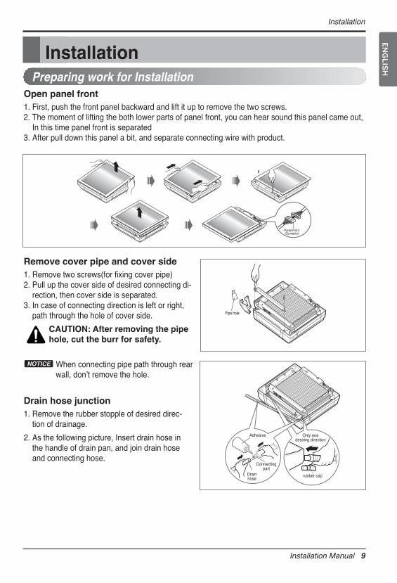
Open panel front1. First, push the front panel backward and lift it up to remove the two screws.2. The moment of lifting the both lower parts of panel front, you can hear sound this panel came out,
In this time panel front is separated3. After pull down this panel a bit, and separate connecting wire with product.
Remove cover pipe and cover side1. Remove two screws(for fixing cover pipe)2. Pull up the cover side of desired connecting di-
rection, then cover side is separated.3. In case of connecting direction is left or right,
path through the hole of cover side.
CAUTION: After removing the pipehole, cut the burr for safety.
When connecting pipe path through rearwall, donʼt remove the hole.
NOTICE
Drain hose junction1. Remove the rubber stopple of desired direc-
tion of drainage.
2. As the following picture, Insert drain hose inthe handle of drain pan, and join drain hoseand connecting hose.
Panel Front Connector
Pipe hole
rubber cap
Only onedesiring direction
Connectingpart
Adhesive
Drainhose
10 Multi Air Conditioner
Installation
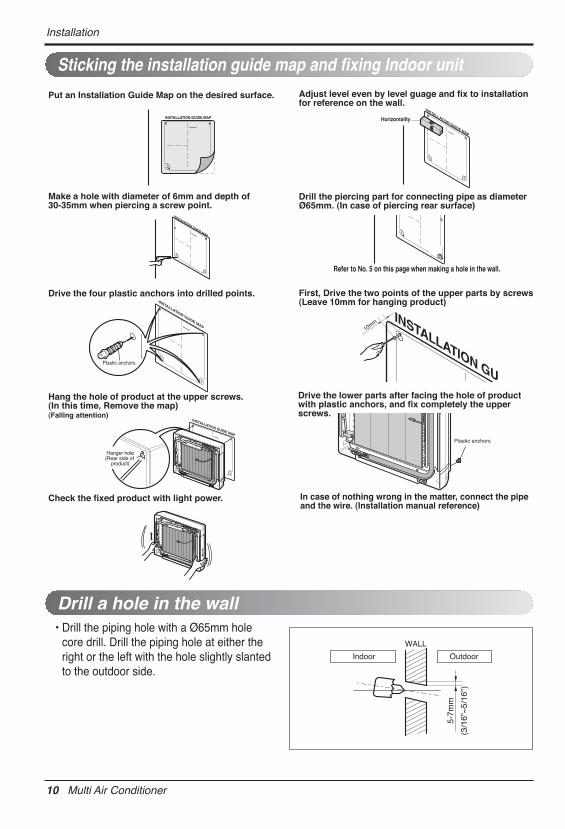
• Drill the piping hole with a Ø65mm holecore drill. Drill the piping hole at either theright or the left with the hole slightly slantedto the outdoor side.
Drill a hole in the wall
5-7m
m
(3/1
6"~
5/16
")
Indoor
WALL
Outdoor
Sticking the installation guide map and fixing Indoor unit
Plastic anchors
INSTALLATION GUIDE MAP
10mmINSTALLATION GU
INSTAIIATION GUIDE MAP
Put an Installation Guide Map on the desired surface.
Make a hole with diameter of 6mm and depth of 30-35mm when piercing a screw point.
Drive the four plastic anchors into drilled points.
Hang the hole of product at the upper screws. (In this time, Remove the map)(Falling attention)
Check the fixed product with light power.
Adjust level even by level guage and fix to installation for reference on the wall.
Drill the piercing part for connecting pipe as diameter Ø65mm. (In case of piercing rear surface)
Refer to No. 5 on this page when making a hole in the wall.
First, Drive the two points of the upper parts by screws(Leave 10mm for hanging product)
Drive the lower parts after facing the hole of product with plastic anchors, and fix completely the upper screws.
In case of nothing wrong in the matter, connect the pipe and the wire. (Installation manual reference)
Horizontality
INSTALLATION GUIDE MAP
Plastic anchors
INSTALLATION GUIDE MAP
INSTALLATION GUIDE MAP
Hanger hole(Rear side of
product)
Installation Manual 11
Installation ENGLIS
H
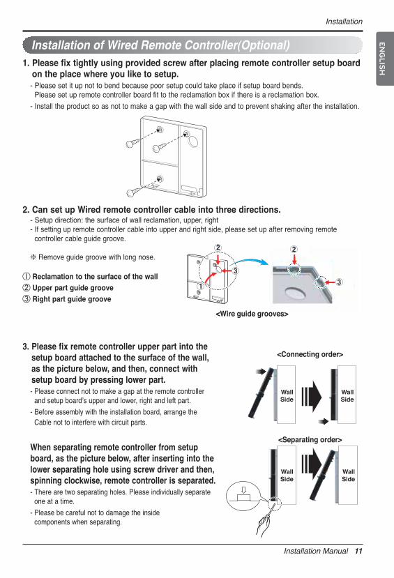
Installation of Wired Remote Controller(Optional)1. Please fix tightly using provided screw after placing remote controller setup board
on the place where you like to setup.- Please set it up not to bend because poor setup could take place if setup board bends.
Please set up remote controller board fit to the reclamation box if there is a reclamation box.
- Install the product so as not to make a gap with the wall side and to prevent shaking after the installation.
2. Can set up Wired remote controller cable into three directions. - Setup direction: the surface of wall reclamation, upper, right- If setting up remote controller cable into upper and right side, please set up after removing remote
controller cable guide groove.
h Remove guide groove with long nose.
① Reclamation to the surface of the wall② Upper part guide groove③ Right part guide groove
WallSide
WallSide
WallSide
WallSide
<Connecting order>
<Separating order>
3. Please fix remote controller upper part into thesetup board attached to the surface of the wall,as the picture below, and then, connect withsetup board by pressing lower part. - Please connect not to make a gap at the remote controller
and setup boardʼs upper and lower, right and left part.
- Before assembly with the installation board, arrange theCable not to interfere with circuit parts.
When separating remote controller from setupboard, as the picture below, after inserting into thelower separating hole using screw driver and then,spinning clockwise, remote controller is separated.- There are two separating holes. Please individually separate
one at a time.
- Please be careful not to damage the inside components when separating.
1
2
3
2
3
<Wire guide grooves>
12 Multi Air Conditioner
Installation
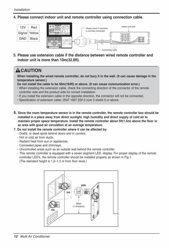
4. Please connect indoor unit and remote controller using connection cable.
5. Please use extension cable if the distance between wired remote controller andindoor unit is more than 10m(32.8ft).
Please check if connectoris normally connected.
Indoor Unit side
Connecting cable
When installing the wired remote controller, do not bury it in the wall. (It can cause damage in thetemperature sensor.) Do not install the cable to be 50m(164ft) or above. (It can cause communication error.)• When installing the extension cable, check the connecting direction of the connector of the remote
controller side and the product side for correct installation.• If you install the extension cable in the opposite direction, the connector will not be connected.• Specification of extension cable: 2547 1007 22# 2 core 3 shield 5 or above.
CAUTION
12V Red
Signal Yellow
GND Black
6. Since the room temperature sensor is in the remote controller, the remote controller box should beinstalled in a place away from direct sunlight, high humidity and direct supply of cold air tomaintain proper space temperature. Install the remote controller about 5ft(1.5m) above the floor inan area with good air circulation at an average temperature.
7. Do not install the remote controller where it can be affected by:- Drafts, or dead spots behind doors and in corners.- Hot or cold air from ducts.- Radiant heat from sun or appliances.- Concealed pipes and chimneys.- Uncontrolled areas such as an outside wall behind the remote controller.- This remote controller is equipped with a seven segment LED. display. For proper display of the remote
controller LED's, the remote controller should be installed properly as shown in Fig.1. (The standard height is 1.2~1.5 m from floor level.)
5feet(1.5meters)
no
no
no
yesOperation unit
ZONE 1 2 3 4
HumidifyJETAUTO
AUTO SWING OPERATION FAN SPEED
Program set
SUB FUNCTIONSET TEMPRoom Temp
HIMEDLO
HeaterDefrostFilter
Preheat
Out doorTime
TimerOnSet no. Time
Off01 03 05 07 09 11 13 15 17 19 21 23
Operation unit
ZONE
12
34
Humidify
JETAUTO
AUTO SWINGOPERATION
FAN SPEED
Program set
SUB FUNCTION
SET TEMP
Room Temp
HI
MED
LO
Heater
Defrost
Filter
Preheat
Out door
Time
Timer
On
Set no. TimeOff 0103
0507
0911
1315
1719
2123
Operation unit
ZONE 1 2 3 4
HumidifyJETAUTO
AUTO SWING OPERATION FAN SPEED
Program set
SUB FUNCTIONSET TEMPRoom Temp
HIMEDLO
HeaterDefrostFilter
Preheat
Out doorTime
TimerOnSet no. Time
Off01 03 05 07 09 11 13 15 17 19 21 23

Installation Manual 13
Flaring Work and Connection of Piping ENGLIS
H
Flaring Work and Connection of PipingFlaring work
Main cause of gas leakage is defect in flaringwork. Carry out correct flaring work in the followingprocedure.
1. Cut the pipes and the cable.• Use the accessory piping kit or the pipes pur-
chased locally.• Measure the distance between the indoor and
the outdoor unit.• Cut the pipes a little longer than measured
distance.• Cut the cable 1.5m(4.9ft) longer than the pipe
length.
2. Burrs removal• Completely remove all burrs from the cut
cross section of pipe/tube.• Put the end of the copper tube/pipe to down-
ward direction as you remove burrs in order toavoid to let burrs drop in the tubing.
3. Putting nut on• Remove flare nuts attached to indoor and out-
door units, than put them on pipe/tube havingcompleted burr removal.(Not possible to put them on after flaring work)
4. Flaring work• Carry out flaring work using flaring tool as
shown below.
Firmly hold copper tube in a bar(or die) as indi-cated dimension in the table above.
5. Check• Compare the flared work with figure.• If flare is noted to be defective, cut off the
flared section and do flaring work again.
Coppertube 90 Slanted Uneven Rough
Pipe
Reamer
Point down
Flare nut
Copper tube
Bar
Copper pipe
Clamp handleRed arrow mark
Cone
Yoke
Handle
Bar"A"
Inclined
Inside is shining without scratches.
Smooth all round
Even lengthall round
Surfacedamaged
Cracked Uneventhickness
= Improper flaring =
mm inch mm inch Ø6.35 1/4 1.1~1.3 0.04~0.05 Ø9.52 3/8 1.5~1.7 0.06~0.07 Ø12.7 1/2 1.6~1.8 0.06~0.07
Outside diameter A
14 Multi Air Conditioner
Flaring Work and Connection of Piping
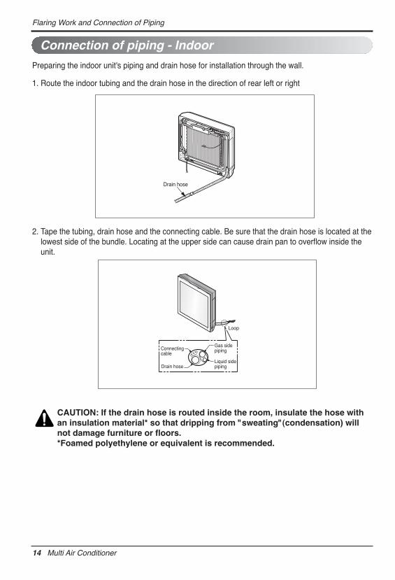
Preparing the indoor unit's piping and drain hose for installation through the wall.
1. Route the indoor tubing and the drain hose in the direction of rear left or right
2. Tape the tubing, drain hose and the connecting cable. Be sure that the drain hose is located at thelowest side of the bundle. Locating at the upper side can cause drain pan to overflow inside theunit.
Connection of piping - Indoor
Drain hose
Connectingcable
Gas sidepiping
Liquid sidepipingDrain hose
Loop
CAUTION: If the drain hose is routed inside the room, insulate the hose withan insulation material* so that dripping from "sweating"(condensation) willnot damage furniture or floors.*Foamed polyethylene or equivalent is recommended.
Installation Manual 15
Flaring Work and Connection of Piping ENGLIS
H
Wrap with vinyl tape
Drain hose
Pipe
Vinyl tape(wide)
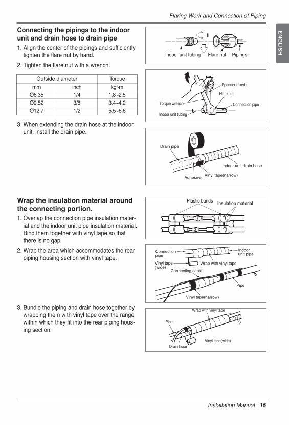
Wrap the insulation material aroundthe connecting portion.1. Overlap the connection pipe insulation mater-
ial and the indoor unit pipe insulation material.Bind them together with vinyl tape so thatthere is no gap.
2. Wrap the area which accommodates the rearpiping housing section with vinyl tape.
3. Bundle the piping and drain hose together bywrapping them with vinyl tape over the rangewithin which they fit into the rear piping hous-ing section.
Connecting the pipings to the indoorunit and drain hose to drain pipe1. Align the center of the pipings and sufficiently
tighten the flare nut by hand.
2. Tighten the flare nut with a wrench.
3. When extending the drain hose at the indoorunit, install the drain pipe.
Indoor unit tubing Flare nut Pipings
Torque wrench
Indoor unit tubing
Spanner (fixed)
Connection pipe
Flare nut mm inch kgf.m Ø6.35 1/4 1.8~2.5 Ø9.52 3/8 3.4~4.2 Ø12.7 1/2 5.5~6.6
Outside diameter Torque
Vinyl tape(narrow)Adhesive
Drain pipe
Indoor unit drain hose
Plastic bands Insulation material
Vinyl tape(narrow)
Connectionpipe
Connecting cable
Vinyl tape(wide)
Wrap with vinyl tape
Indoor unit pipe
Pipe
16 Multi Air Conditioner
Flaring Work and Connection of Piping
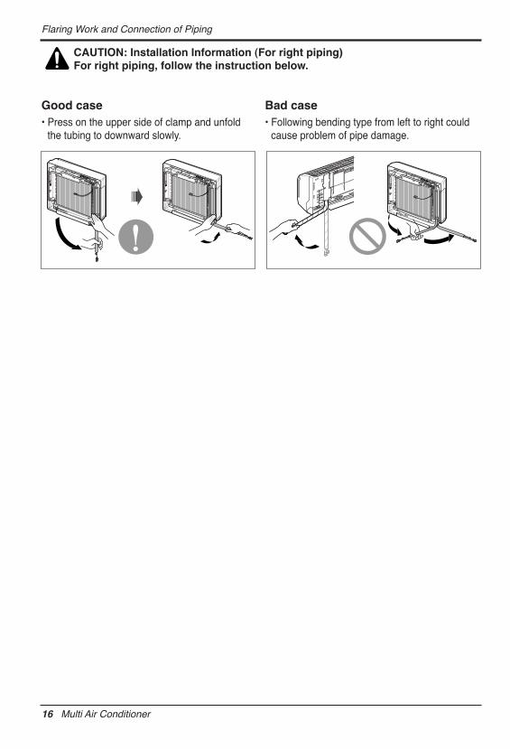
CAUTION: Installation Information (For right piping)For right piping, follow the instruction below.
Good case• Press on the upper side of clamp and unfold
the tubing to downward slowly.
Bad case• Following bending type from left to right could
cause problem of pipe damage.

Installation Manual 17
Connecting the Cable between Indoor Unit and Outdoor Unit ENGLIS
H
Connecting the Cable between Indoor Unit and Outdoor Unit
Connect the cable to the indoor unit by connecting the wires to the terminals on the controlboard individually according to the outdoor unit connection. (Ensure that the color of the wiresof the outdoor unit and the terminal No. are the same as those of the indoor unit.)The ground wire should be longer than the common wires.The circuit diagram is not subject to change without notice.When installing, refer to the electrical diagram behind the front panel of Indoor Unit. The wiring for the outdoor unit can be found on the inside of the Outdoor Unit control cover.
Connect the cable to the Indoor unit.
RECOMMENDATION:• The circuit diagram is subject to change without notice. • Be sure to connect wires according to the wiring diagram.• Connect the wires firmly, so that they can not be pulled out easily.• Connect the wires according to color codes by referring to the wiring diagram.
RECOMMENDATION: The power cord connected to the outdoor unit shouldcomply with the following specifications: NRTL Recognized(for example, UL orETL recognized and CSA certified).
GN/YL
20mm(25/32 inch)
RECOMMENDATION: When using separate wires as the power cord, please secureseparate wires in the control box panel using tie wraps to hold all wires in place.
n Connecting cable The power connecting cable between the outdoor andindoor units must comply with the following specifications:NRTL Recognized (for example, UL or ETL recognized andCSA certified). AWG 18 is the minimum recommended wire size, however, the selected conductors must comply with localcodes and be suitable for installation in wet locations.

18 Multi Air Conditioner
Connecting the Cable between Indoor Unit and Outdoor Unit
1. Remove the control cover from the unit byloosening the screw.Connect the wires to the terminals on the controlboard individually as the following.
2. Secure the cable onto the control board.
3. Re-attach the cover control to the original positionusing the screws.
:
1. Use connection cable NRTL(UL, ETL, CAS…) listed and stranded copper(4) THHN conductors,sunlight (UV) resistant ROHS compliant PVC jacket 600V direct burial listed, approved for wetconditions. Temperature rated for –20℃(-4℉) to 90℃(194℉). And this cable should be enclosedin conduit.
WARNING:
• Be sure to comply with local and national codes while running the wire from the indoor unit tothe outdoor unit(size of wire and wiring method, etc).
• Every wire must be connected firmly.• No wire should be allowed to touch refrigerant tubing, the compressor or any moving parts.• The communication wirings of air conditioner should be separate and isolated from external
deviceʼs electric wiring such as computers, elevator, radio & Television broadcasting facilities,as well as medical imaging offices.
NOTICE
1(L1) 2(L2) 3
Cover control
Lock nut(field supply)
Conduit(field supply)

Installation Manual 19
Connecting the Cable between Indoor Unit and Outdoor Unit ENGLIS
H
WARNING: Loose wiring may cause the terminal to overheat or result in unitmalfunction. A fire hazard may also exist. Therefore, be sure all wiring is tightlyconnected.
When connecting each power wire to the corresponding terminal, follow instructions "How to connectwiring to the terminals" and fasten the wire tightly with the fixing screw of the terminal plate.
How to connect wiring to the terminals◼ For strand wiring(1) Cut the wire end with a wire cutter or wire-
cutting pliers, then strip the insulation to exposethe strand wiring about 10 mm(3/8").
(2) Using a screwdriver, remove the terminalscrew(s) on the terminal plate.
(3) Using a round terminal fastener or pliers,securely clamp each stripped wire end with around terminal.
(4) Position the round terminal wire, and replaceand tighten the terminal screw using ascrewdriver.
Power supply cable
Connecting Cable
Str
ip 1
0 m
m(3
/8")
Roundterminal
Connecting cable
Loosening theterminal blockscrew
Fastening the wire tightly
Strand wire
20 Multi Air Conditioner
Checking the Drainage, Forming the Pipings and Long Pipe Setting
Checking the Drainage, Forming the Pipings and Long Pipe SettingChecking the drainage
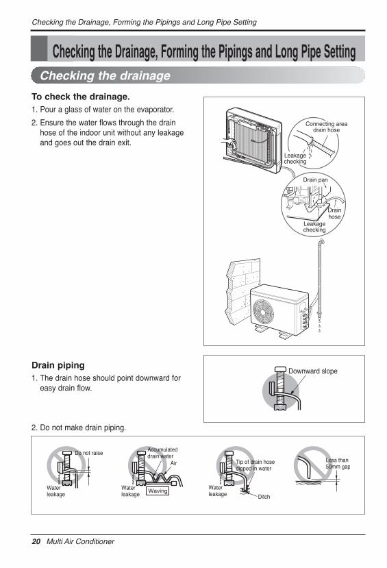
To check the drainage.1. Pour a glass of water on the evaporator.
2. Ensure the water flows through the drainhose of the indoor unit without any leakageand goes out the drain exit.
Drain piping1. The drain hose should point downward for
easy drain flow.
2. Do not make drain piping.
Drain pan
Drainhose
Leakagechecking
Connecting areadrain hose
Leakagechecking
Downward slope
Do not raiseAccumulateddrain water
Tip of drain hose dipped in water
Air
WavingWaterleakage
Waterleakage Ditch
Less than 50mm gap
Waterleakage

Installation Manual 21
Panel Front Assembly ENGLIS
H
Panel Front Assembly1. First, Check the side cover
assembly exactly, Fix power cordin the bottom groove of cover sideleft.
2. Assemble connecting lead wirewith controller and first fix theupper part of panel front, thenmatch the lower part of panel front
3. Suspend hook of front panel inthe groove after contract lower of2 screws.
Panel FrontConnector

22 Multi Air Conditioner

US1. Please call the installing contractor of your product, as warranty service will be provided by them.2. If you have service issues that have not been addressed by the contractor, please call 1-888-865-3026.
CANADA Service call Number # : (888) LG Canada, (888) 542-2623