Embed Size (px)
DESCRIPTION
….Suggestions on installation methods which help prolong refrigerator life and increase convenience in usage. ….For customers who require recommendation on refrigerator usage and maintenance can contact dealer from which the cabinet was bought for after-sales service.
Citation preview

INSTALLATION & MAINTENANCEMANUAL
Koldtech Refr igerator & Freezer
1

The following procedure should be followed for trouble free installation
2
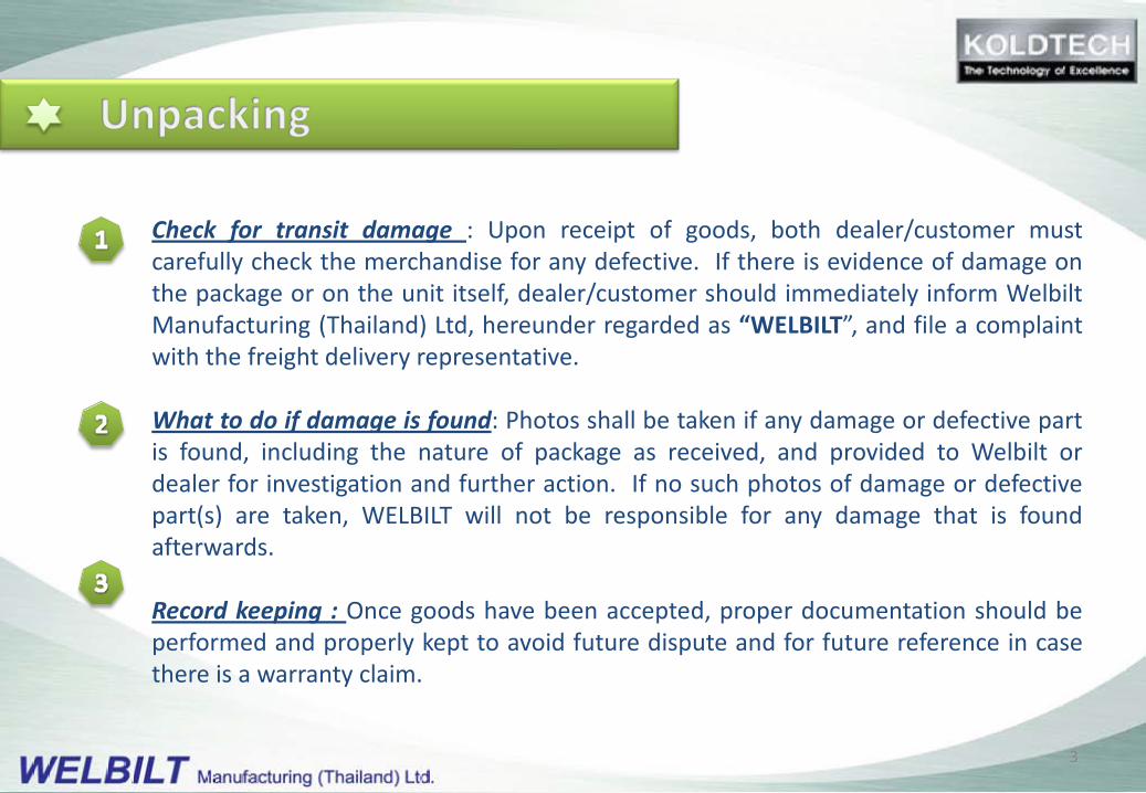
Check for transit damage : Upon receipt of goods, both dealer/customer mustcarefully check the merchandise for any defective. If there is evidence of damage onthe package or on the unit itself, dealer/customer should immediately inform WelbiltManufacturing (Thailand) Ltd, hereunder regarded as “WELBILT”, and file a complaintwith the freight delivery representative.
What to do if damage is found: Photos shall be taken if any damage or defective partis found, including the nature of package as received, and provided to Welbilt ordealer for investigation and further action. If no such photos of damage or defectivepart(s) are taken, WELBILT will not be responsible for any damage that is foundafterwards.
Record keeping : Once goods have been accepted, proper documentation should beperformed and properly kept to avoid future dispute and for future reference in casethere is a warranty claim.
3
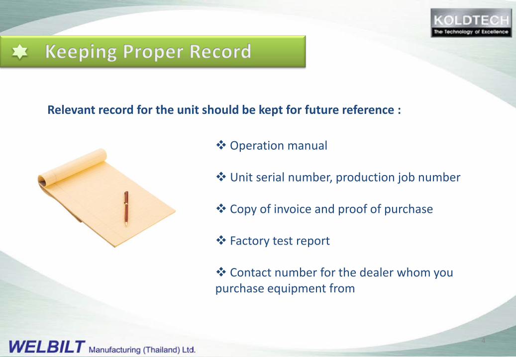
Operation manual
Unit serial number, production job number
Copy of invoice and proof of purchase
Factory test report
Contact number for the dealer whom you purchase equipment from
Relevant record for the unit should be kept for future reference :
4
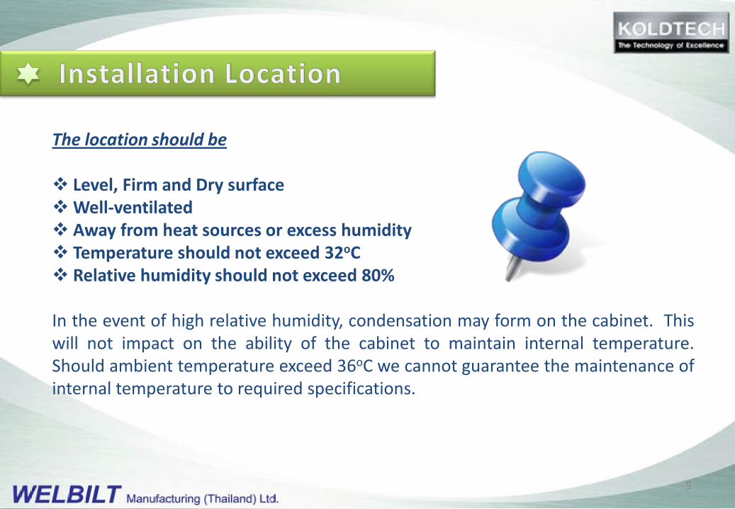
The location should be
Level, Firm and Dry surfaceWell-ventilated Away from heat sources or excess humidity Temperature should not exceed 32oC Relative humidity should not exceed 80%
In the event of high relative humidity, condensation may form on the cabinet. Thiswill not impact on the ability of the cabinet to maintain internal temperature.Should ambient temperature exceed 36oC we cannot guarantee the maintenance ofinternal temperature to required specifications.
5

300300100
TEMPERATURE POWER LAMP
Minimum clearance above the cabinet should be 300 mm.
Minimum clearance behind the cabinet should be 100 mm.
Minimum clearance on the side of the cabinet should be 50 mm.
6
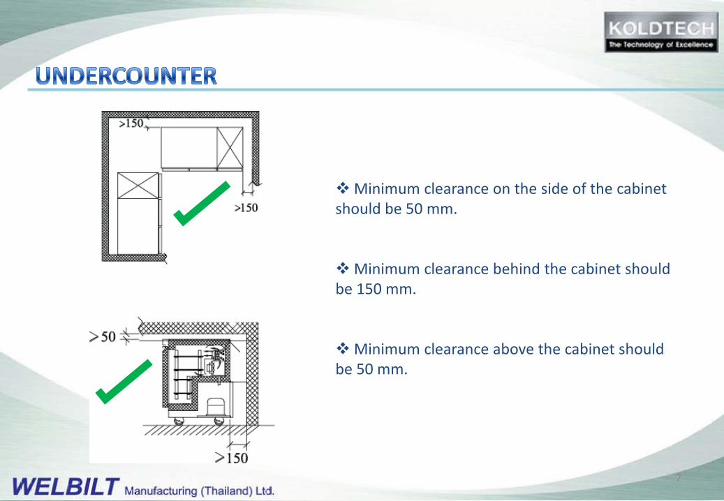
Minimum clearance on the side of the cabinet should be 50 mm.
Minimum clearance behind the cabinet should be 150 mm.
Minimum clearance above the cabinet should be 50 mm.
7
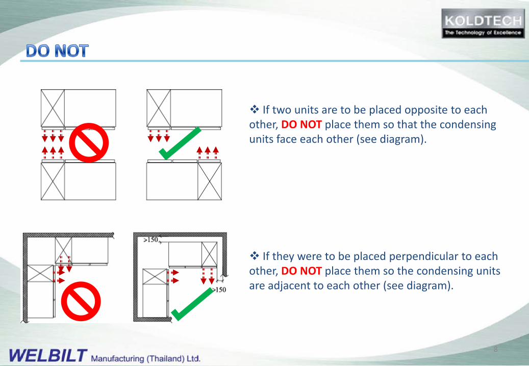
If two units are to be placed opposite to each other, DO NOT place them so that the condensing units face each other (see diagram).
If they were to be placed perpendicular to each other, DO NOT place them so the condensing units are adjacent to each other (see diagram).
8
TEMPERATURE POWER LAMP
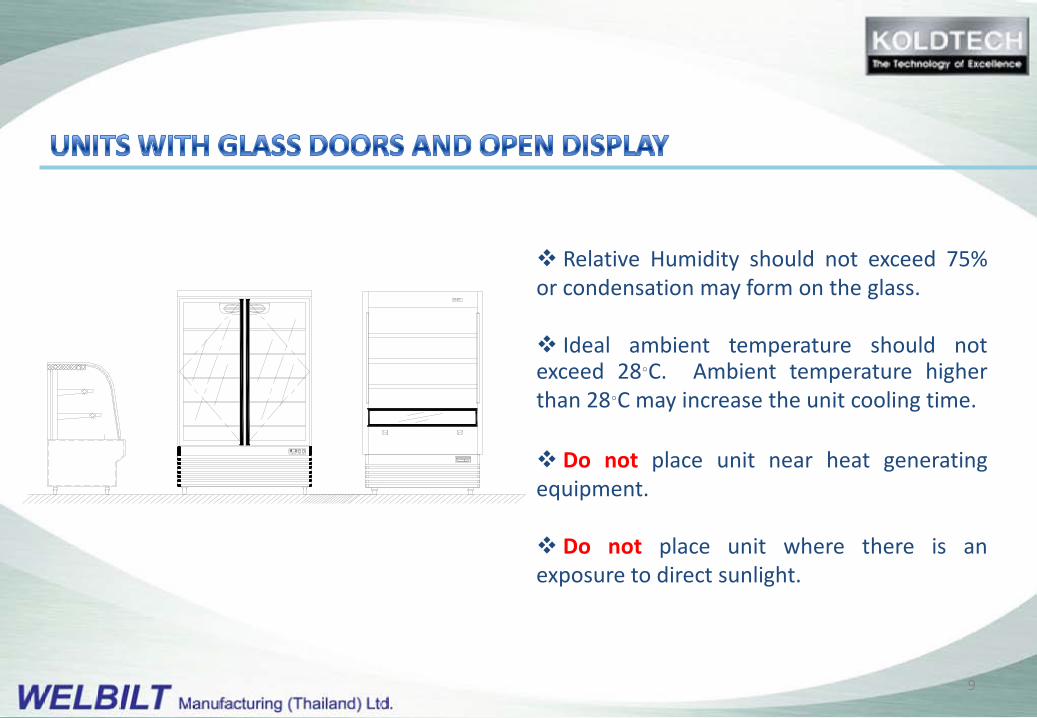
Relative Humidity should not exceed 75%or condensation may form on the glass.
Ideal ambient temperature should notexceed 28°C. Ambient temperature higherthan 28°C may increase the unit cooling time.
Do not place unit near heat generatingequipment.
Do not place unit where there is anexposure to direct sunlight.
9
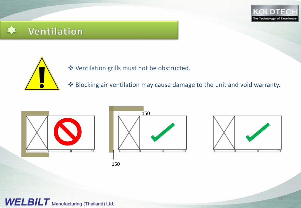
Ventilation grills must not be obstructed.
Blocking air ventilation may cause damage to the unit and void warranty.
150
150
10
Most of KOLDTECH models employ self evaporate drainage system, using recycled heatfrom the refrigeration system.
Some special models may require external drain line. Connect the external drain line ifrequired before you proceeding.
Precaution has been taken to ship the unit in an upright position. If the unitis tilted during transit lubricating oil may shift from the reservoir. Operatingthe unit may cause excessive wear or damage to the compressor’s movingparts.
It is recommended that the unit be left standing upright for 24 hoursbefore operation.
11

Earth Ground : For safety reasons, the equipment must beproperly earth grounded to prevent the possibility of electricalshock. Check and make sure that the outlet is properly grounded.If a grounded plug is not available, a separate earth ground must beinstalled to prevent any electrical hazard.
Proper rated or circuit breaker or fuse must be installed in theoutlet circuit.
Check for proper supply voltage before plugging in the unit.Please refer to voltage requirements on the nameplate of the unit.
Proper rated circuit breaker or fuse…….
12
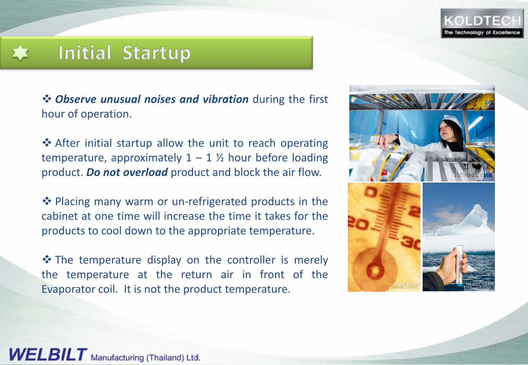
Observe unusual noises and vibration during the firsthour of operation.
After initial startup allow the unit to reach operatingtemperature, approximately 1 – 1 ½ hour before loadingproduct. Do not overload product and block the air flow.
Placing many warm or un-refrigerated products in thecabinet at one time will increase the time it takes for theproducts to cool down to the appropriate temperature.
The temperature display on the controller is merelythe temperature at the return air in front of theEvaporator coil. It is not the product temperature.
13
To prevent compressor damage, the unit is equipped with a Time Delay Circuit, which shall activate compressor in approximately 2 minutes after turning on the power or after restarting.
The controller is pre-set from the factory for optimum operation.
Any service performed by unauthorized service agent or unauthorized tampering with the unit may cause damage and will void the warranty.
Contact your dealer or an authorised service agent if there is any service required.
14
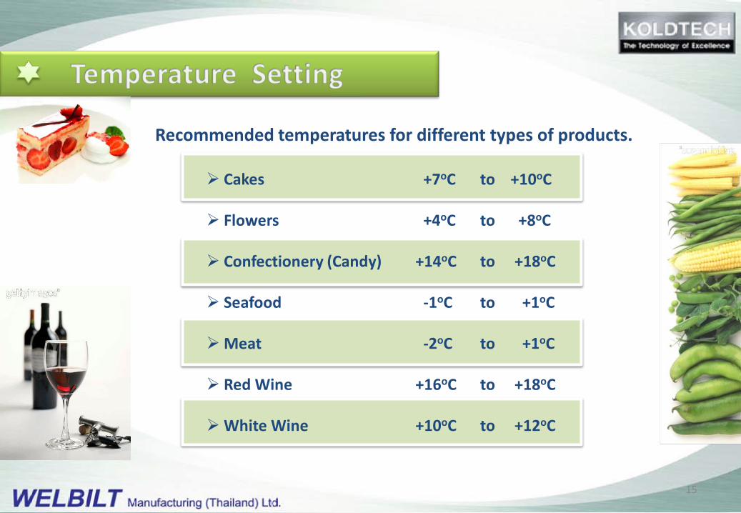
Recommended temperatures for different types of products.
Cakes +7oC to +10oC
Flowers +4oC to +8oC
Confectionery (Candy) +14oC to +18oC
Seafood -1oC to +1oC
Meat -2oC to +1oC
Red Wine +16oC to +18oC
White Wine +10oC to +12oC
15

(SET) To display target set pointIn programming mode, it selects a parameter or confirms an operation (like an Enter key on computer keyboard)
(DEF) To start a manual defrost
(UP) To see the maximum stored temperatureIn programming mode it browses the parameter codes or increases the displayed value.
(DOWN) To see the minimum stored temperatureIn programming mode it browses the parameter codes or decreases the displayed value.
To switch the equipment ON of OFF.
Lighting (Not enabled on some model)
16
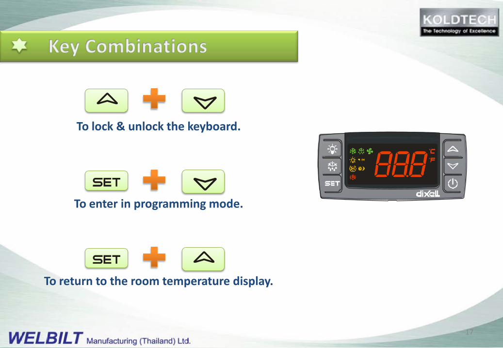
To lock & unlock the keyboard.
To enter in programming mode.
To return to the room temperature display.
17
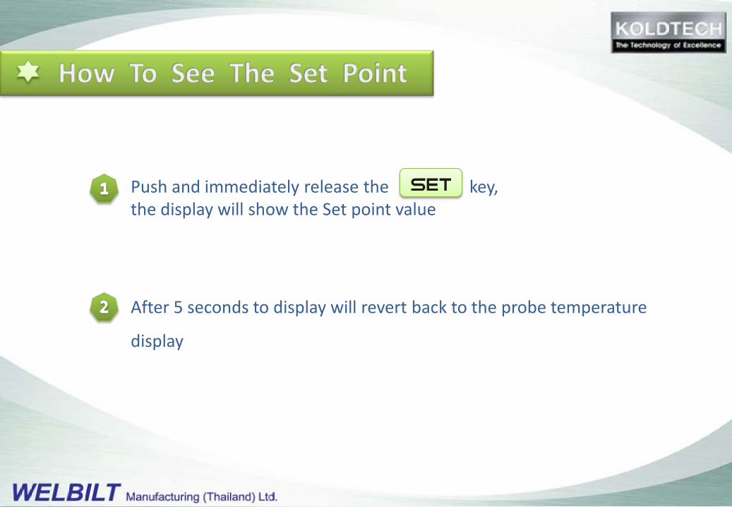
Push and immediately release the key,the display will show the Set point value
After 5 seconds to display will revert back to the probe temperature
display

Push the key for more than 2 seconds to change the Set point value
The value of the set point will be displayed and the °C or °F and LED starts blinking
To change the Set value push the or arrows within 10 seconds.
To store the new set point value, push the key again or wait 10 seconds.
19
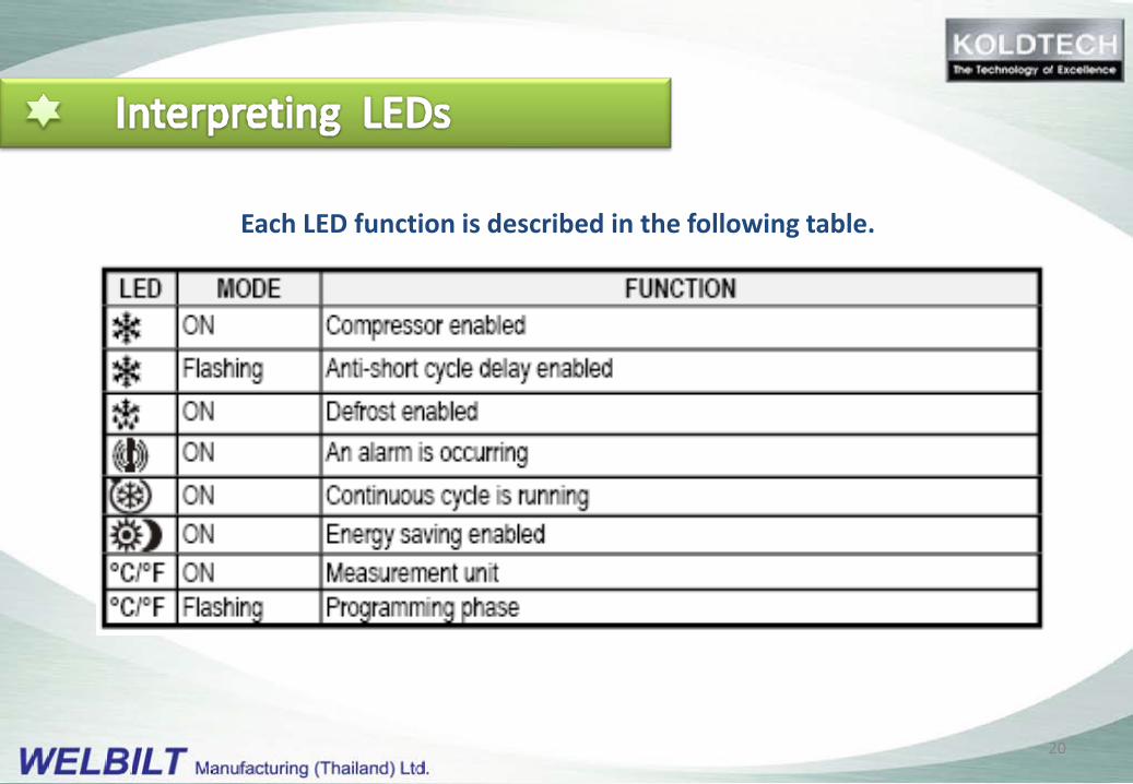
Each LED function is described in the following table.
20
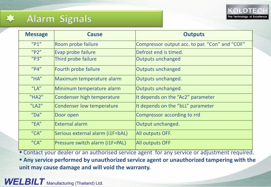
Message Cause Outputs“P1” Room probe failure Compressor output acc. to par. “Con” and “COF”“P2”“P3”
Evap probe failureThird probe failure
Defrost end is timed.Outputs unchanged
“P4” Fourth probe failure Outputs unchanged
“HA” Maximum temperature alarm Outputs unchanged.
“LA” Minimum temperature alarm Outputs unchanged."HA2" Condenser high temperature It depends on the “Ac2” parameter
"LA2" Condenser low temperature It depends on the “bLL” parameter
“Da” Door open Compressor according to rrd
“EA” External alarm Output unchanged.
“CA” Serious external alarm (i1F=bAL) All outputs OFF.
“CA” Pressure switch alarm (i1F=PAL) All outputs OFF
Contact your dealer or an authorised service agent for any service or adjustment required. Any service performed by unauthorized service agent or unauthorized tampering with the unit may cause damage and will void the warranty.
21
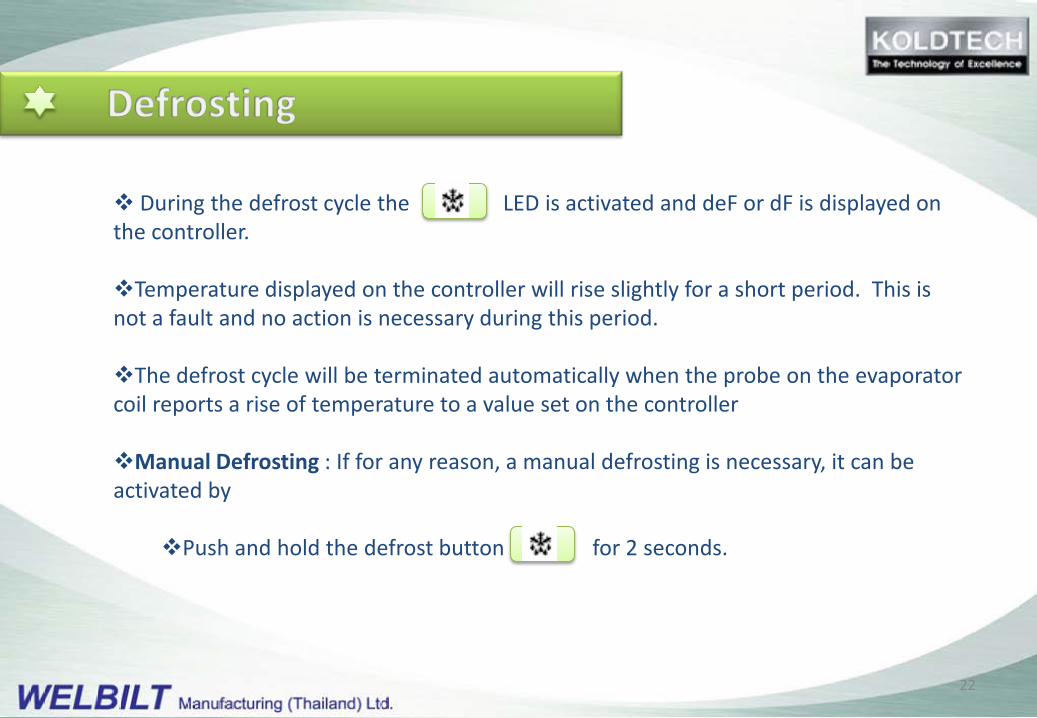
During the defrost cycle the LED is activated and deF or dF is displayed on the controller.
Temperature displayed on the controller will rise slightly for a short period. This is not a fault and no action is necessary during this period.
The defrost cycle will be terminated automatically when the probe on the evaporator coil reports a rise of temperature to a value set on the controller
Manual Defrosting : If for any reason, a manual defrosting is necessary, it can be activated by
Push and hold the defrost button for 2 seconds.
22
Probe alarms: In case one of the probes malfunctions, the controller shall report Probe alarms (P1, P2….)
The controller has been pre-programmed from the factory to operate on time sequence.
Customer should contact dealer and have the probe changed as soon as possible.
Controller malfunction: If there is malfunction in the controller, the unit will not be able to operate.
One of the main causes of controller failure is the frequent fluctuation of the supply power.
Take care to switch off and unplug the units while there is high fluctuation of the supply power to prevent damage to the unit.
Unit can resume operation when voltage stabilizes.
23
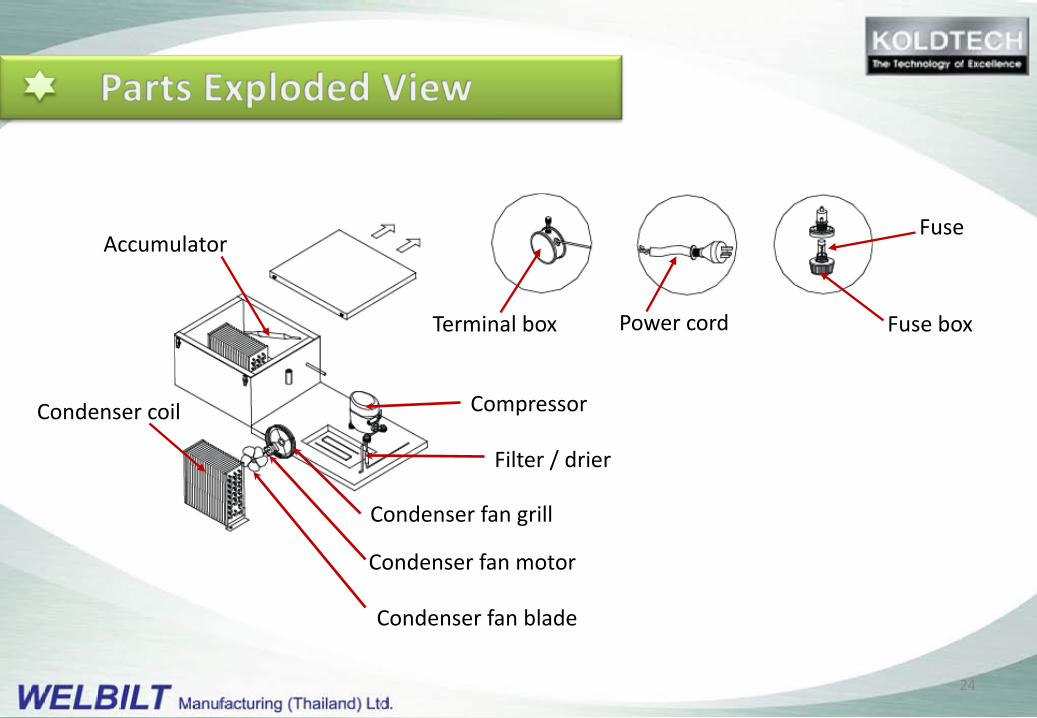
Accumulator
Condenser coil
Condenser fan motor
Condenser fan blade
Condenser fan grill
Filter / drier
Compressor
Terminal box Power cord
Fuse
Fuse box
24
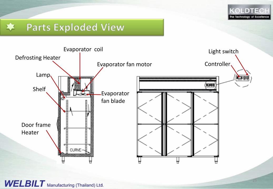
Controller
Light switchEvaporator coil
Evaporator fan motor
Evaporator fan blade
Defrosting Heater
Lamp
Shelf
Door frameHeater
25
KOLDTECH units feature Mono Block System
The whole refrigeration system is mounted on a Single Chassis
The complete system can be easily removed for service
A replacement system can be installed to minimize operation down time
26
The maintenance instructions below are for basic maintenance that should
be done on a regular basis by the owner/operator.
27
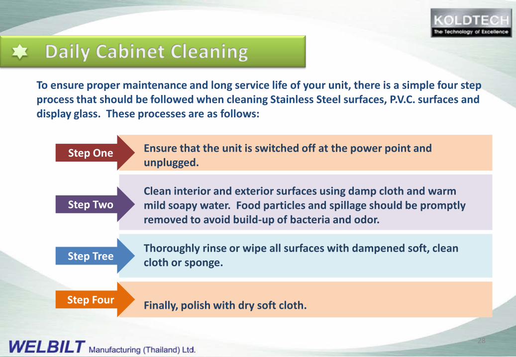
Ensure that the unit is switched off at the power point and unplugged.
Clean interior and exterior surfaces using damp cloth and warm mild soapy water. Food particles and spillage should be promptly removed to avoid build-up of bacteria and odor.
Thoroughly rinse or wipe all surfaces with dampened soft, clean cloth or sponge.
Finally, polish with dry soft cloth.
Step One
Step Two
Step Tree
Step Four
To ensure proper maintenance and long service life of your unit, there is a simple four step process that should be followed when cleaning Stainless Steel surfaces, P.V.C. surfaces and display glass. These processes are as follows:
28
Do not use aggressive cleaning agent or solventsfor cleaning. Avoid using cleaning agent withmixture of chlorine or detergent.
Do not use sharp instrument, wire brush, steelwool or grainy scouring pad.
In some areas, particularly in seaside locations, stainless steel can be subject tosurface discoloration or “tea staining”. This can be removed with an appropriatecleaning agent that contains 10% Sodium citrate. Ask your supplier of cleaningchemicals for a suitable brand. Be sure to clean and rinse off all surface well offerstain removal.
29
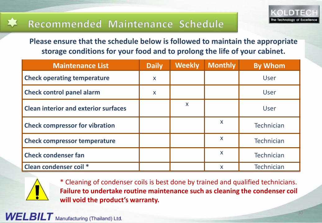
Maintenance List Daily Weekly Monthly By WhomCheck operating temperature x User
Check control panel alarm x User
Clean interior and exterior surfacesx
User
Check compressor for vibration x Technician
Check compressor temperature x Technician
Check condenser fan x Technician
Clean condenser coil * x Technician
* Cleaning of condenser coils is best done by trained and qualified technicians. Failure to undertake routine maintenance such as cleaning the condenser coil will void the product’s warranty.
Please ensure that the schedule below is followed to maintain the appropriate storage conditions for your food and to prolong the life of your cabinet.
30
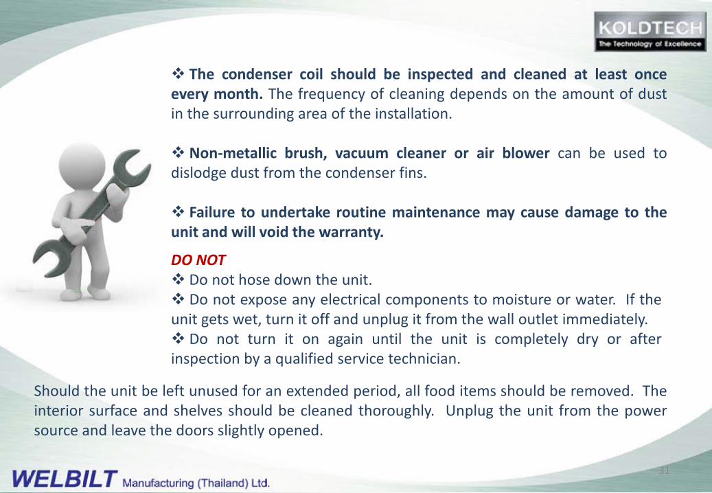
Should the unit be left unused for an extended period, all food items should be removed. Theinterior surface and shelves should be cleaned thoroughly. Unplug the unit from the powersource and leave the doors slightly opened.
The condenser coil should be inspected and cleaned at least onceevery month. The frequency of cleaning depends on the amount of dustin the surrounding area of the installation.
Non-metallic brush, vacuum cleaner or air blower can be used todislodge dust from the condenser fins.
Failure to undertake routine maintenance may cause damage to theunit and will void the warranty.
DO NOT Do not hose down the unit. Do not expose any electrical components to moisture or water. If theunit gets wet, turn it off and unplug it from the wall outlet immediately. Do not turn it on again until the unit is completely dry or afterinspection by a qualified service technician.
31
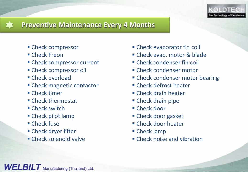
Preventive Maintenance Every 4 Months
Check compressor Check Freon Check compressor current Check compressor oil Check overload Check magnetic contactor Check timer Check thermostat Check switch Check pilot lamp Check fuse Check dryer filter Check solenoid valve
Check evaporator fin coil Check evap. motor & blade Check condenser fin coil Check condenser motor Check condenser motor bearing Check defrost heater Check drain heater Check drain pipe Check door Check door gasket Check door heater Check lamp Check noise and vibration
32

Whenever any problem arises, dealer should be contact to assist inidentifying the cause, whether it is caused by inappropriate operation,maintenance procedures, intrinsic problems or defective from factory.
In case the problem cannot be identified by dealer, relevant photos andinformation should be sent back to manufacturer (WELBILT) for furtherinvestigation.
In case the investigation indicates that the dealer has not doneproper testing and repairing base on the recommended procedure or thereis modification of the unit, WELBILT reserves the right to counter claim forrepairs work.
33

warrants equipment sold against defects inmaterial and workmanship for a period of twelve (12)months from the date of installation or fifteen (15)months from date of shipment (whichever comes first).Warranty is limited to replacement of defectivematerials or rectification of faulty workmanship.
Access to warranty is conditional on the equipmentbeing correctly installed, used under normal conditions,for the purpose that equipment is designed for, properlymaintained and cared for as per instruction in thismanual.
34

Any consequential loss, damages or expenses directly or indirectly arising from useof this unit.
If the unit has been subjected to misuse, neglect, alteration, incorrect installation,accident, use of inappropriate aggressive chemicals, flooding, fire or acts of God.
Damage caused during transportation.
Breakage of glass, bulbs, lamps, fluorescent tubes gasket, plastic components orany expendable items.
Penalty or additional labor costs for installation, removal or repair of the product.
Freight on spare parts.
35
The following procedure should be followed to obtain warranty service.
Make a copy of the WARRANTY CLAIM FORM. Fill in information using data from the QCReport Form.
Describe the nature of faults, with any related technical data and attach photographs ofthe components that have evidence of malfunction.
Send the completed WARRANTY CLAIM FORM, pictures and proof of purchase by e-mail orfax to the dealer that you purchased the unit from or KOLDTECH authorised representative.
Manufacturer and the authorized representative reserve the right to reject warranty claimwhere circumstances fail to meet the warranty conditions.
All warranty parts requested will be charged to the customer’s account unless a warrantyclaim is approved. Standard credit policies will be applied.
36
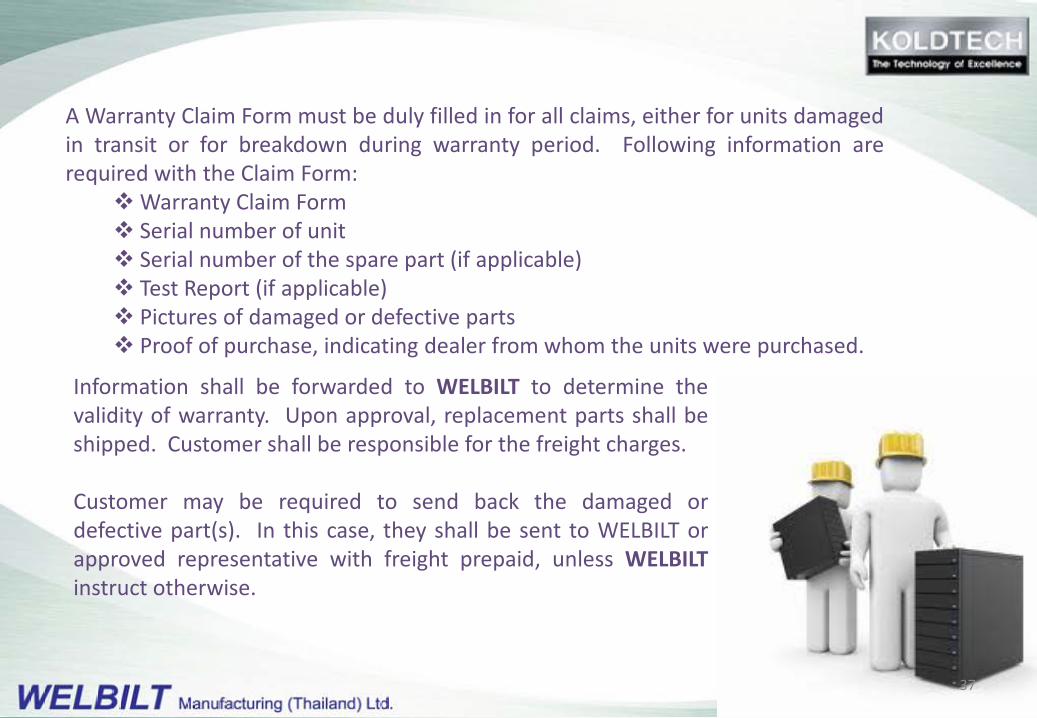
A Warranty Claim Form must be duly filled in for all claims, either for units damagedin transit or for breakdown during warranty period. Following information arerequired with the Claim Form:
Warranty Claim Form Serial number of unit Serial number of the spare part (if applicable) Test Report (if applicable) Pictures of damaged or defective parts Proof of purchase, indicating dealer from whom the units were purchased.
Information shall be forwarded to WELBILT to determine thevalidity of warranty. Upon approval, replacement parts shall beshipped. Customer shall be responsible for the freight charges.
Customer may be required to send back the damaged ordefective part(s). In this case, they shall be sent to WELBILT orapproved representative with freight prepaid, unless WELBILTinstruct otherwise.
37
Observe safe practice by disconnecting all electrical supply before performing any kind of maintenance.
The electrical and refrigeration components of this product should only be accessed by an authorizer service agent. Do not attempt to disassemble the unit in any way. Any unauthorized disassembly, modification, alterations will void your warranty.
Contact your dealer or authorized service agent for any service and repair. The contact number can be found in the Operation Manual.
38

39