Embed Size (px)
Citation preview

PV500-26 06/18
INSTALLATION & MAINTENANCE MANUAL
QuickDraw® BOILER WATER
PACKAGED WATER HEATER
with AquaPLEX® Storage and Semi-instantaneous Tank
Installation and service must be performed by a qualified service installer, service agency or qualified plumbing contractor. IMPORTANT: THIS MANUAL CONTAINS INFORMATION REQUIRED FOR INSTALLATION, OPERATION AND MAINTENANCE OF THIS EQUIPMENT. READ AND FOLLOW THE INFORMATION IN THIS MANUAL AND ALL OTHER PROVIDED INSTRUCTIONS, LABELS AND MARKINGS BEFORE INSTALLING, OPERATING OR SERVICING THIS UNIT.
TO THE INSTALLER: After installation, these instructions must be given to the equipment user or left near the appliance. SPECIAL INSTRUCTIONS TO THE OWNER: Retain this manual for future reference. These instructions contain important information that will help you in maintaining and operating this appliance.
PVI INDUSTRIES, LLC - Fort Worth, Texas 76111 - Web www.pvi.com - Phone 1-800-433-5654

QuickDraw® BOILER WATER
with AquaPLEX® Storage and Semi-instantaneous Tank
2 PV500-26 06/18
TABLE OF CONTENTS
1. Safety Considerations
2. Product Descriptions
3. Typical Piping Diagrams
4. Water Heater Installation
4.1 Checking Equipment Before You Install
4.2 Codes
4.3 Electrical
4.4 Location
4.5 Installation
4.6 Service Clearances and Clearance to Combustibles
5. General Guidelines
5.1 Water Inlet / Outlet Connections
5.2 Boiler Water Piping
5.3 Relief Valve Piping
5.4 Filling the Unit
6. Operating and Safety Controls
6.1 Operating Temperature Control
6.2 Thermostat Settings – for QuickDraw Semi-Instantaneous Heaters only
6.3 High Water Temperature Limit Control
6.4 Electronic Low Water Cut-Off (optional)
6.5 Sequence of Operation
7. TEMPTRAC Electronic Controller Panel
7.1 Principle of Operation
7.2 Upper LED Readout
7.3 Lower LED Readout
7.4 Control Buttons
7.5 Key Combinations
7.6 LED Icon Legend
7.7 To View the Setpoint
7.8 To Change the Setpoint
7.9 To Set the Current Time and Day (Military Time)
7.10 To Set the Energy Saving Time (Nighttime Setback)
7.11 To Set Modulation Parameters
7.12 To Change Other Parameters
7.13 LED Display Alarm Messages
7.14 Audible Alarm
7.15 Alarm Recovery
QuickDraw® BOILER WATER
with AquaPLEX® Storage and Semi-instantaneous Tank
3 PV500-26 06/18
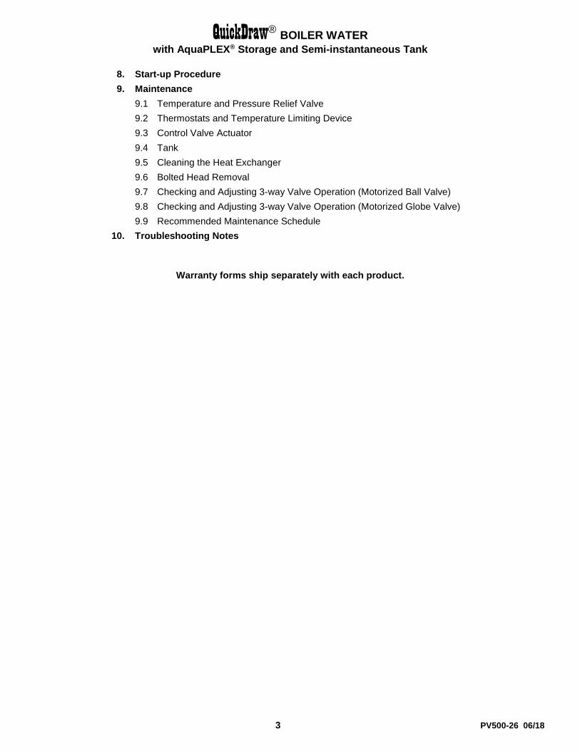
8. Start-up Procedure
9. Maintenance
9.1 Temperature and Pressure Relief Valve
9.2 Thermostats and Temperature Limiting Device
9.3 Control Valve Actuator
9.4 Tank
9.5 Cleaning the Heat Exchanger
9.6 Bolted Head Removal
9.7 Checking and Adjusting 3-way Valve Operation (Motorized Ball Valve)
9.8 Checking and Adjusting 3-way Valve Operation (Motorized Globe Valve)
9.9 Recommended Maintenance Schedule
10. Troubleshooting Notes
Warranty forms ship separately with each product.

QuickDraw® BOILER WATER
with AquaPLEX® Storage and Semi-instantaneous Tank
4 PV500-26 06/18
1 SAFETY CONSIDERATIONS
IMPORTANT SAFETY NOTE
It takes only 5 seconds of skin contact with 140°F water to cause a second degree burn! You must protect against high water temperatures at all
lavatories, tubs, showers and other points of hot water contact.
Accidental scalding from high water temperatures is a greater risk in some types of installations. Some examples are:
HOMES FOR THE MENTALLY HANDICAPPED HOMES FOR THE PHYSICALLY HANDICAPPED
HOSPITALS AND NURSING HOMES ELDER CARE FACILITIES AND REST HOMES ORPHANAGES AND CHILD CARE FACILITIES
OTHER INSTALLATIONS - WHERE RESPONSE TO CONTACT WITH HOT WATER
MAY BE SLOWER OR WHERE THE DANGER OF HOT WATER CONTACT IS GREATER
Thermostatically controlled mixing valves must be used in the design of the potable hot water system.
Potable hot water should be tempered to no more than 110°F
when used for bathing or other personal uses.
Good engineering practice mandates the use of thermostatically controlled mixing valves set at 120°F or less to keep the delivered water
temperature below scalding temperatures.
QuickDraw® BOILER WATER
with AquaPLEX® Storage and Semi-instantaneous Tank
5 PV500-26 06/18
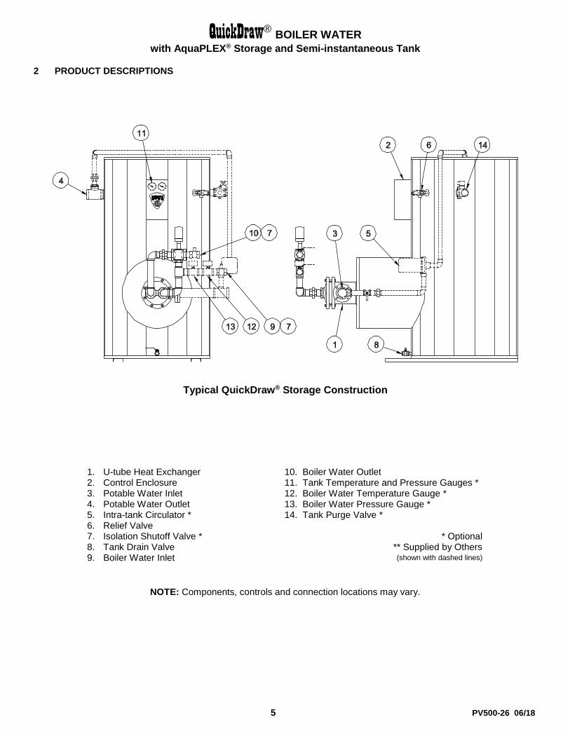
2 PRODUCT DESCRIPTIONS
Typical QuickDraw® Storage Construction
1. U-tube Heat Exchanger 10. Boiler Water Outlet 2. Control Enclosure 11. Tank Temperature and Pressure Gauges * 3. Potable Water Inlet 12. Boiler Water Temperature Gauge * 4. Potable Water Outlet 13. Boiler Water Pressure Gauge * 5. Intra-tank Circulator * 14. Tank Purge Valve * 6. Relief Valve 7. Isolation Shutoff Valve * * Optional 8. Tank Drain Valve ** Supplied by Others 9. Boiler Water Inlet (shown with dashed lines)
NOTE: Components, controls and connection locations may vary.

QuickDraw® BOILER WATER
with AquaPLEX® Storage and Semi-instantaneous Tank
6 PV500-26 06/18
Typical QuickDraw® Semi-Instantaneous Construction
1. U-tube Heat Exchanger 10. Boiler Water Outlet 2. Control Enclosure 11. Electronic Operating Control * 3. Potable Water Inlet 12. Boiler Water Temperature Gauge * 4. Potable Water Outlet 13. Boiler Water Pressure Gauge * 5. Intra-tank Circulator * 14. Tank Purge Valve * 6. Relief Valve 15. Tank Pressure Gauge * 7. Isolation Shutoff Valve * 8. Tank Drain Valve * Optional 9. Boiler Water Inlet ** Supplied by Others
(shown with dashed lines)
NOTE: Components, controls and connection locations may vary.
QuickDraw® BOILER WATER
with AquaPLEX® Storage and Semi-instantaneous Tank
7 PV500-26 06/18
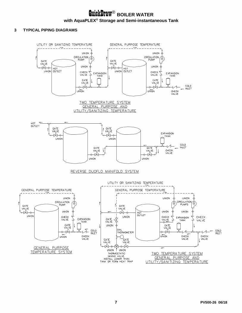
3 TYPICAL PIPING DIAGRAMS
QuickDraw® BOILER WATER
with AquaPLEX® Storage and Semi-instantaneous Tank
8 PV500-26 06/18
4 WATER HEATER INSTALLATION
4.1 Checking Equipment Before You Install
Inspect the unit completely upon receipt from the freight carrier before signing the bill of lading. Inspect the appliance and all accompanying parts for signs of impact or mishandling. Verify the total number of pieces shown on packing slips with those actually received. Contact the freight carrier immediately if any damage or shortage is detected.
4.2 Codes
The equipment shall be installed in accordance with the instructions in this manual, appliance markings and supplemental instructions and in compliance with those installation regulations in force in the local area where the installation is to be made. These shall be carefully followed in all cases. Authorities having jurisdiction shall be consulted before installation is made. All appliances conform to the latest edition of the ASME Boiler and Pressure Vessel Code, Section IV, Part HLW or Section VIII.
4.3 Electrical Requirements
The heater is wired for 120VAC/1ph/60Hz volts and must be electrically grounded in accordance with local codes, or in the absence of local codes, with the latest edition of the National Electrical Code NFPA-70. When unit is installed in Canada, it must conform to the Canadian Electrical Code (CEC), CSA C22.1, and/or local electrical codes.
1. Branch circuit protection and disconnecting means must be furnished by the installer. Refer to the wiring diagram provided with this unit when installing or troubleshooting the electrical components of this heater.
2. All wiring must be in accordance with all local, state, or federal codes.
3. Provide proper overload protection for the system’s circulating pump.
NOTE: Use only copper wire of proper sizing for incoming service. The warranty on this unit does not cover damage resulting from the use of aluminum wiring.
Utiliser du fil de cuivre de la taille appropriée pour le service électrique entrant. Les dommages résultant de l'utilisation de fil d'aluminium seront exclus du champ d'application de la garantie de cet appareil.
4.4 Location
1. Locate the unit in a clean and dry area as close as possible to the greatest hot water usage and as near to boiler water and/or electrical power as practical.
2. Install the unit on a firm, level foundation.
3. Locate the foundation on a pitched floor near a suitable drain, or make other provisions to prevent contact to areas of the building subject to water damage should a boiler water or a water connection leak. The drain must be sufficient to contain water in excess of 210°F.
4.5 Installation
WARNING: Use industry standard safe rigging methods, such as including the use straps and spreader bars and lifting from the water heater base skid assembly, when attempting to lift or move this product. Failure to follow industry safe rigging methods could result in property damage, serious injury or death.
1. Check the data decal on the heater. Be sure the electrical supply is adequate for the installation.
2. Carefully remove all shipping supports and bracing.
3. Do not attempt to move or lift heater by the plumbing connections or heat exchanger. Lift only by the skid using industry standard safe rigging methods.
4. Provide sufficient clearance in front of heat exchanger to facilitate maintenance and removal. See “Service Clearances” below.
5. Install shut-off valves and unions on the inlet and outlet water piping for servicing. Use caution when threading pipe nipples into tank connections to prevent cross threading, or over-tightening. Always use a back-up wrench on tank nipples when tightening unions, valves, etc.

QuickDraw® BOILER WATER
with AquaPLEX® Storage and Semi-instantaneous Tank
9 PV500-26 06/18
6. Use only non-ferrous water piping and fittings for potable water plumbing and connections. Do not use galvanized pipe or fittings. Use of ferrous or galvanized pipe or fittings can cause rust to form.
7. Insulate hot water and return circulation lines. Also, if subject to freezing during shutdown or during operation, insulate all water piping and take whatever steps are necessary to keep the appliance and all water containing pipes and components from freezing. IMPORTANT: Do not use the plumbing connected to the appliance as a ground for welding or any other purpose.
8. This appliance is equipped with a temperature and pressure relief valve(s) rated for the input. The relief valve must be pipe to and attached to a suitable open drain (Relief Valve Piping).
9. Pipe the drain valve to a suitable open drain.
10. Thermal Expansion Tank – If the water heater is installed in a closed water supply system, such as one having a back-flow preventer in the cold water line, provide thermal expansion control. Contact the water supplier or local plumbing inspector for additional information.
4.6 Service Clearances and Clearance to Combustibles
The appliance must not be installed on a combustible floor, or on a non-combustible floor covering combustible material. A minimum clearance of 6” must be provided from any combustible material. However, the recommended clearance is 24” at the top and front, 18” at left and right sides of the appliance. Optional equipment may increase the clearance requirements. Allow sufficient space for installing and servicing connections such as water, electrical, pump and other auxiliary equipment. Distance minimale aux matériaux combustibles est de 15 cm sur le dessus et les côtés et ne doit pas être installé sur un plancher combustible.

QuickDraw® BOILER WATER
with AquaPLEX® Storage and Semi-instantaneous Tank
10 PV500-26 06/18
5 GENERAL GUIDELINES
5.1 Water Inlet / Outlet Connections
1. Make inlet and outlet water connections directly to the threaded bolt-on bronze tank flanges. Over tightening connections to the flanges may cause damage to the flange or tank and are not covered by warranty.
2. For ease of service, install unions on inlet and outlet piping to the unit.
3. Piping and components connected to the water heater must be suitable for potable water, for the water temperatures they will experience and for their application.
4. After plumbing the unit and checking for leaks, the heat exchanger and boiler water and hot water piping should be insulated. Insulation will reduce wasteful heat loss and will help protect operators from contacting hot surfaces.
WARNING: Insulate or guard and hot water surfaces. Uninsulated or unguarded steam and hot water surfaces can cause burns instantly.

QuickDraw® BOILER WATER
with AquaPLEX® Storage and Semi-instantaneous Tank
11 PV500-26 06/18
5.2 Boiler Water Piping
WARNING: All system piping to the heat exchanger plumbing must be adequately supported. Failure to provide adequate support will result in excessive loads on the heat exchanger connections that can cause hot water or steam discharge resulting in property damage, scalding and personal injury or death. This appliance will perform in accordance with the boiler water and domestic water temperatures and flows to which it is connected. To obtain the desired performance, it must be installed to operate with the temperature and flow conditions specified when selecting the appliance. The boiler water piping must be appropriately sized and include a strainer, isolation valves, pressure gauges, drain valve, and over pressure protection where required. The domestic water piping must also be appropriately sized and include isolation valves, drain valve, temperature and pressure relief valve and expansion tank or other means of expansion control. Boiler water supply piping should be sized to deliver sufficient hot water to the appliance without excessive pressure drop. A heat trap of at least 3x pipe diameters must be used for the boiler water supply piping as depicted in the above typical piping arrangement. When larger sized boiler water supply and return piping is not furnished by PVI, the installation must comply with the typical piping installation diagram shown below. It is important that a minimum of 3x pipe diameters heat trap be installed on the boiler water supply line to achieve proper performance of the heat exchanger.
A system bypass from supply to return is required when using two-way valves to avoid “deadhead” operation of the boiler water loop. Flow through the bypass must be adjusted to provide sufficient flow to enable the water heater to operate at maximum capacity. When two or more heaters are piped in parallel it is important that the piping systems are balanced to assure the full combined capacity is realized. Reverse return piping is recommended for multiple unit installations.

QuickDraw® BOILER WATER
with AquaPLEX® Storage and Semi-instantaneous Tank
12 PV500-26 06/18
5.3 Relief Valve Piping
The water heater is supplied with a pressure and temperature relief valve, sized in accordance with ASME requirements. Each relief valve must be piped and secured to a suitable floor drain. No reducing coupling or other restriction can be installed in the discharge line. It is strongly recommended that this valve should be manually operated at least once a year. (See Maintenance.)
WARNING: Do not install a reducing coupling, valve or other restriction between the relief valve discharge and a suitable floor drain. Such restriction could prevent the valve from fully relieving if the pressure settings are exceeded, which could result in property damage, personal injury or death.
WARNING: The relief valve discharge must be piped to a suitable floor drain to avoid exposure to hot discharge water during relief valve operation. Exposure to hot discharge water can cause water damage and/or burns resulting in property damage, personal injury or death.
WARNING: Secure the relief valve pipe to a suitable floor drain such that very hot water does not openly splash during a significant relief valve discharge. If the relief valve pipe is not routed and secured to a suitable drain, hot water discharge can result in property damage, scalding and personal injury or death.
5.4 Filling the Unit
1. Fill the system with water. To be sure that the unit is not “air bound,” open the relief valve. Leave the valve open until a steady flow of water is observed. Close valve and complete filling the system.
2. In hard water areas, potable water treatment should be used to reduce introduction of minerals into the system. Minerals in the water can collect on the tubes and heat-exchanger surfaces reducing the life of the product. Heat exchanger failure due to scale accumulation is not covered by the product warranty.
3. Make sure there are no system leaks. DO NOT use petroleum based stop-leak products. All system leaks must be repaired.

QuickDraw® BOILER WATER
with AquaPLEX® Storage and Semi-instantaneous Tank
13 PV500-26 06/18
6 OPERATING AND SAFETY CONTROLS
WARNING: Turn off all electrical service to the appliance when accessing the remote connections located inside the control cabinet and close and fasten the control cabinet cover before restoring electrical service to the appliance. Terminals and components in the control cabinet are high voltage. If the electrical service is not turned off and these terminals or components are touched, a dangerous shock can result in property damage, personal injury or death. Coupez l'alimentation avant intervention sur l'appareil.
6.1 Operating Temperature Control
An adjustable digital operating control is located in the front control panel. The control is factory pre-set at approximately 120ºF. To adjust the setpoint to deliver the desired water temperature, press and release the Set key on the face of the control. When setpoint adjustment is enabled, use the arrow keys to adjust the set point to the desired system temperature. See TempTrac Electronic Controller Panel in this manual for more information.
Le thermostat est réglé à environ 49 degrés Celsius. Températures de l'eau supérieures à 52 degrés Celsius peut causer instantanément de graves brûlures ou la mort de brûlures. Suivez les instructions dans le manuel d'installation pour modifier la température de l'eau.
6.2 Thermostat Settings – For QuickDraw Semi-Instantaneous Heaters
The adjustable operating temperature control is located just above the front control panel cover. This control utilizes a temperature sensing thermistor located in the control flange on top of the tank. Follow the safety instructions and warnings included in this manual and with the product, when adjusting the set point of the operating temperature control to deliver the desired water temperature.
The setpoint (SET) determines the desired stored water temperature in the tank and is factory set at approximately 120°F. If the tank temperature decreases below the set point a call for heat sequence is activated. The heating sequence is turned off when the tank temperature again reaches the set point value.
Le thermostat est réglé à environ 49 degrés Celsius. Températures de l'eau supérieures à 52 degrés Celsius peut causer instantanément de graves brûlures ou la mort de brûlures. Suivez les instructions dans le manuel d'installation et de maintenance pour modifier la température de l'eau. To View the Setpoint
1. Press and quickly release the “SET” key. This will display the setpoint for 5 seconds.
To Change the Set Point
1. Press and hold the “SET” key for at least 2 seconds to enter the setpoint change mode.
2. The setpoint is displayed and the LEDs of the first and third digits blink.
3. To change the value, use the “UP” and “DOWN” keys.
4. The new value can be stored either by pressing the “SET” key (the control restores temperature display) or by waiting the exit time-out to expire (15 seconds).
Key Combinations
1. TO UNLOCK THE KEYBOARD: Press and hold the “UP” + “DOWN” keys for 3 seconds. When the “PON” flashing message is displayed, the keys are unlocked.
2. TO LOCK THE KEYBOARD: Press and hold the “UP”+ “DOWN” keys for 3 seconds. When the “POF” flashing message is displayed, the keys are locked.
3. TO RETURN TO TEMPERATURE DISPLAY: Press the “SET” +”UP” keys.

QuickDraw® BOILER WATER
with AquaPLEX® Storage and Semi-instantaneous Tank
14 PV500-26 06/18
6.3 High Water Temperature Limit Control
The appliance is equipped with an adjustable temperature limit control and a non-adjustable high temperature limit control. These controls are located inside the control cabinet and are accessed by removing the bottom cover.
The adjustable limit control is an auto reset type and should be adjusted at least 10 degrees above the set point of the Operating Thermostat.
The high limit is an auto reset type with a fixed set point, but is optionally available as a manual reset type. If the high limit is a manual reset type, it cannot be reset until the water temperature has dropped below its reset point.
6.4 Electronic Low Water Cut-Off (Optional)
When the water level is above the electrode position in the tank, the reset pushbutton will energize the control (LED will be lit). The control remains energized until the water level recedes below the electrode position (LED will not be lit). Unless otherwise specified, there is a three-second time delay on decreasing level. Water level must be below tank probe location for full three seconds before control de-energizes.
6.5 Sequence of Operation (Refer to figure below)
1. When power is supplied through the unit’s On-Off switch, if the stored water temperature is below the operating thermostat set point, the limit operating circuit closes creating a call-for-heat-demand, which energizes the actuator on the three-way mixing valve.
2. The three-way mixing valve returns circulating boiler water to the boiler supply loop through its bypass ports. On a call-for heat, the actuator motor runs and the actuator shaft moves causing the valve to divert the boiler water through the heat exchanger before it is returned to the boiler supply loop.
3. When the demand is satisfied, the limit operating circuit opens and the valve actuator is de-energized. The actuator motor stops running and the actuator shaft spring returns to the diverting position causing the boiler water to divert through the bypass ports and return to the boiler water supply loop.

QuickDraw® BOILER WATER
with AquaPLEX® Storage and Semi-instantaneous Tank
15 PV500-26 06/18
7 TEMPTRAC™ ELECTRONIC CONTROLLER PANEL
7.1 Principle of Operation
The water heater operates to satisfy the setpoint of the TempTrac digital control whose sensor is located near the energy source of the water heater tank. Demand (flow) will typically create a drop in temperature, thus activating the water heater to add heat to the stored water. This setpoint is the desired water temperature to maintain.
7.2 Upper LED Readout
The default display of the upper readout (Probe 2) is the water temperature near the hot water outlet.
This readout can display additional information by pushing the EXT button to cycle through the following items:
The modulation rate of the valve, if applicable, indicated by 0 to 100%.
The temperature difference between Probe 1 and Probe 2.
All of the display information described above is available for monitoring through the optional MODBUS RTU interface.
7.3 Lower LED Readout
The default display of the lower readout (Probe 1) is the water temperature sensed near the middle of the water heater tank. This sensing location serves as the primary control temperature for the TempTrac.
7.4 Control Buttons
SET Displays and modifies the temperature set points.
In programming mode, it selects a parameter or confirms an operation.
UP Displays and modifies the energy saving (Night Time setback) settings.
In programming mode, it browses the parameter codes or increases a displayed value.
DOWN Displays the working hours of the load relays.
In programming mode, it browses the parameter codes or decreases a displayed value.
CLOCK Changes lower display from the stored water temperature to current time and day.
EXT
Changes upper display from Probe 1 temperature to Probe 3 temperature, displays the temperature difference of the stored water temperature minus Probe 2 temperature and firing rate of the burner from 0 to 100%. In programming mode it sets the 4-20mA output (password is required).
ON/OFF Switches the control ON or OFF.
(See TempTrac User Manual PV500-41 for full description)

QuickDraw® BOILER WATER
with AquaPLEX® Storage and Semi-instantaneous Tank
16 PV500-26 06/18
7.5 Key Combinations
Use the UP + DOWN key to lock and unlock the keyboard.
Use the SET + DOWN arrow to enter the programming mode.
Use the SET + UP arrow to exit the programming mode.
7.6 LED Icon Legend
LED MODE Function
ON Temperatures are displayed in degrees Fahrenheit
ON Temperatures are displayed in degrees Celsius
Flashing Call for heat time delay or remote enable/disable is in standby (disabled)
ON Call for heat is on
Flashing Second stage time delay (On 2-stage units only)
ON Second stage on or the AL2 alarm output is enabled.
Flashing Output 3 time delay
ON Output 3 relay on
ON Modulation output signal is in manual control mode or forced to the i1S setting by digital input 1
ON Modulation output signal is automatically controlled by temperature probe 1
Flashing Modulation output time delay is activated.
Ext ON Probe 3 is displayed
FLASHING Digital input 2 (alarm) is activated
FLASHING Digital input 3 (alarm) is activated
ON Lower display is displaying the time
FLASHING Alarm signal
FLASHING Programmed working hours limit is exceeded
ON Working hours are displayed in Lower LED readout
ES ON The energy saving function is running
7.7 To View the Setpoint
Push and release the SET key to see the set point value.
To return to normal display, press SET + UP or wait 15 seconds without pressing any key.
7.8 To Change the Setpoint
Push the SET key. The upper display will show the “St1” parameter name, while the lower display will show its value.
Use the UP or DOWN key to cycle through the parameter names.
Push the SET key to modify a parameter value. The value starts flashing in the lower display.
To change it push the UP or DOWN keys. Push the SET key again to confirm the value and pass to the setting of next set point.
Repeat the operations described at points 3, 4, 5.
To Exit: press SET + UP or wait 15 seconds without pressing any key.
NOTE: Each point has a time out of 15 seconds. If any key is pushed within 15 seconds the controller exits the set points programming procedure.
NOTE: The set value is stored even when the procedure is exited by waiting the time-out to expire.

QuickDraw® BOILER WATER
with AquaPLEX® Storage and Semi-instantaneous Tank
17 PV500-26 06/18
7.9 To Set the Current Time and Day (Military Time)
Push and hold the CLOCK key for more than 3 seconds. The LED icon starts flashing and the “Hur” (hour) parameter name is displayed in the Upper LED readout, its value is displayed in the Lower LED readout.
Pushing the UP or DOWN key alternates the LED readouts between the following:
“Hur” (hour) in the Upper readout and its value in the lower readout
“Min” (minute) in the Upper readout, its value in the Lower readout
“dAY” (day) in the Upper readout, its value in the Lower readout
To adjust a value, press the SET key and the value in the Lower LED will start flashing. Change the value by pressing the UP or DOWN keys. When correct, press the SET key.
To exit push SET + UP keys or wait 15 seconds without pressing any keys.
NOTE: This device recognizes Sunday as the first day of the week and Saturday as the last.
7.10 To Set the Energy Saving Time (Nighttime Setback)
Push and hold the UP key for more than 3 seconds and the first parameter of the energy saving will be displayed.
Use the UP or DOWN keys to browse them.
To change a value, push the SET key followed by UP or DOWN and then the SET key again.
To exit from the menu, press SET and UP or wait for 30 seconds.
7.11 To Set Modulation Parameters
Push and hold the EXIT key for more than 3 seconds and the LED will switch ON and a passkey will be required to view and manually change the modulation % value. Passkey is “321”.
Upon entering the password, the modulation % value will be displayed in the lower display.
To manually adjust this value, push the SET key; the value will start flashing. Adjust it by using the UP or DOWN keys and then the SET key again.
To exit from the menu, press SET and UP keys together or wait for 30 seconds.
7.12 To Change Other Parameters
Push the SET and DOWN arrow simultaneously for 3 seconds.
Select the required parameter. The name of the parameter is on the upper display; its value is on the lower display.
Press the SET key: the value of the parameter will start blinking.
Use UP or DOWN to change the value.
Press SET to store the new value and move to the following parameter.
To Exit: Press SET + UP or wait 15s without pressing a key.

QuickDraw® BOILER WATER
with AquaPLEX® Storage and Semi-instantaneous Tank
18 PV500-26 06/18
7.13 LED Display Alarm Messages
Alarm messages are displayed in the upper LED readout and alternate with the default display. An alarm LED ICON is also illuminated. (See TempTrac User Manual PV500-41 for full description.)
ALARM
MESSAGE CAUSE RESULTS OF ALARM CONDITION
RECOMMENDED
ACTION
“P1” TP1 probe failure
Tank temperature sensor is not connected or is reading incorrectly. Call for heat and burner modulation output signal will revert to low fire.
Check wiring and sensor Terminals 14 & 17
“P2” TP2 probe failure Temperature sensor is not connected or is reading incorrectly.
Check wiring and sensor Terminals 15 & 17
“P3” TP3 probe failure Temperature sensor is not connected or is reading incorrectly or flue gas temperature protection is disabled (if used).
Check wiring and sensor Terminals 16 & 17
“HA” High temperature limit setpoint exceeded
Audible alarm sounds, operation continues. Manual reset required
“LA” Low temperature alarm Audible alarm sounds, operation continues.
AL2
Digital input 3 is activated for one or more of the following:
Flame failure or any control component failure, if equipped with alarm on any failure option
Unit de-energized after time delay. Audible alarm sounds. On some products, the alarm contacts (Output 2) may close for remote indication of alarm. Internal alarm register will communicate an alarm condition through the Modbus RTU communication link (if equipped).
Manually reset required
AL3 Digital input 2 is activated Unit de-energized after timer delay. Manually reset required
Mn1 Maintenance alarm for output 1 Audible alarm sounds, operation continues. Check wiring and sensor
Mn2 Maintenance alarm for output 2 Audible alarm sounds, operation continues. Check wiring and sensor
Mn3 Maintenance alarm for output 3 Audible alarm sounds, operation continues. Check wiring and sensor
“rtc” The real time clock has lost its setting
Energy saving function disabled. Reprogram clock
CONTROL
MESSAGE CAUSE RESULTS OF CONTROL CONDITION NOTES
On
A call-for-heat condition The burner operating sequence should begin. If the burner does not operate, check safety devices or Remote Proving Interlock
Flashing
The remote enable/disable has been triggered
The small flame icon will flash indicating the standby state
The R1-R2 terminals have been opened by the remote master control. The heater will remain in standby.
Integral circulation pump
The integral circulation pump will operate until the water temperature has equalized
Pump may operate before, during or after the call-for-heat

QuickDraw® BOILER WATER
with AquaPLEX® Storage and Semi-instantaneous Tank
19 PV500-26 06/18
7.14 Audible Alarm
The TempTrac audible alarm is activated each time a connected alarm condition occurs. The following are representative alarm conditions that may be connected to and activate the TempTrac audible alarm (some alarms may be connected to and operate separately from the TempTrac on some products).
High/low water temperature alarm
Probe failures
External thermostat limit failure
Low water
The audible alarm is silenced by pressing any button (alarm condition still present).
7.15 Alarm Recovery
Probe failure alarm automatically ends after normal operation is re-established. Check connections before replacing the probe.
Temperature alarms “HA” and “LA” automatically stop as soon as probe 1 senses temperatures within normal operating parameters.
Digital input 2 & 3 alarms recover when condition(s) listed above are normalized and any button is pressed (if used). Resetting the alarm condition may require resetting individual safety devices or cycling main power switch.
RTC alarm stops after programming the real time clock.
RTF alarm requires the replacement of the real time clock.
For additional information, contact the PVI Industries Customer Service Dept at 800-433-5654.

QuickDraw® BOILER WATER
with AquaPLEX® Storage and Semi-instantaneous Tank
20 PV500-26 06/18
8 START-UP PROCEDURE
1. When placing the unit into operation, open relief valve to purge air from top of tank and begin to fill the tank with cold water. Check for plumbing leaks. Be sure the tank is completely filled before closing the relief valve.
CAUTION: Do not energize the heater or circulating pump until the tank is full of water. Serious damage may result.
2. Push control switch, located on the control box, to “ON” to activate the three-way valve and thermostats. Check the valve for operation; the valve actuator motor should “run” to open the valve when operating switch is pushed “ON”. Check operating thermostat settings.
Temperature Setting: The operating thermostat is set at the factory at approximately 120°F and the upper operating thermostat (if supplied) is set at approximately 130°F. Adjustment may be made by turning the thermostat’s dial to the desired temperature. The temperature limiting device is factory set at 200°F.
CAUTION: Gradually introduce fluids to the unit. Failure to do so can cause damage to the heat exchanger.
3. Push the operating switch to “OFF” before opening manual main boiler water supply valve. Do not admit boiler water to the unit suddenly when empty or cold to prevent thermal shock. Gradually open boiler water supply valve until all passages of the heat exchanger are filled. Slowly bring the unit up to temperature.
WARNING: Do not operate unit under conditions in excess of those specified on nameplate and ASME data plate. Failure to operate the heat exchanger within the specified design pressure and temperature may result in damage to the heat exchanger, property damage, personal injury or death.
4. Open nearby hot water tap to maintain a flow of water through the tank when starting up units. Regulate flow of water through the tank to allow the control valve to cycle off and on, and check operation of all safety and operating controls.
5. In all installations, there should be no pulsation or water hammer since this causes vibration and strain with resulting leaks.
6. Retighten bolting on all gasketed joints after the heat exchanger has reached temperature to prevent leaks and gasket failures. Retightening should be done uniformly and in a diametrically staggered pattern (see “Maintenance” for proper torque specs).
a. On high pressure and high temperature applications or any application where spiral wound gaskets are required, it is recommended that the gasketed joints of the heat exchanger be retightened to the required torque (see “Maintenance”) after 24 hours at operating pressures and temperatures to compensate for any relaxation or creep that may have occurred.
b. In shutting down, remove all power from the system. Close all boiler water and cold water supply valves to the unit.
c. If the unit is removed from service for an extended period of time, it must be drain completely to eliminate the possibility of freezing and corrosion from stagnant water conditions.
QuickDraw® BOILER WATER
with AquaPLEX® Storage and Semi-instantaneous Tank
21 PV500-26 06/18
9 MAINTENANCE
WARNING: Turn off all electrical service to the appliance when accessing the remote connections located inside the control cabinet. These terminals are high voltage. If the electrical service is not turned off and these terminals are touched, a dangerous shock causing personal injury or death could occur. Close and fasten the control cabinet cover before restoring electrical service to the appliance.
9.1 Temperature and Pressure Relief Valve
Operate the temperature and pressure relief valve at least once a year by lifting the lever briefly. If the valve does not open and close properly when testing, it must be replaced with a like relief valve.
9.2 Thermostats and Temperature Limiting Device
The temperature limiting device and thermostat temperature sensors extend into the water in the tank. Depending on the water conditions in your area, scale may coat the sensors. This coating will affect accuracy of sensors and can allow water temperature to exceed the desired limits. Remove and inspect these controls at necessary intervals. Remove scale if present.
9.3 Control Valve Actuator
The boiler water control valve actuator is sealed and requires no maintenance. Durability of valve stems and packing is dependent upon maintaining non-damaging water conditions. Inadequate water treatment or filtration can result in corrosion, scale, and abrasive particle formation. Scale and particulates can result in stem and packing scratches and can adversely affect packing life and other parts of the hydronic system. Contact the manufacturer for replacement packing and stem & plug assembly, or motorized ball valve assembly.
9.4 Tank
Depending on water quality and operating temperature, scale can form during operation and will accumulate on the bottom of the tank. Natural minerals in water forms scale, which precipitates out during the heating cycles. Some water supplies contain more of these minerals than others, so scale buildup will occur more rapidly. Other factors affecting the scale buildup are the amount of hot water used and the temperature of the water. The more hot water used the more fresh water containing the scale-forming minerals come into the tank. As the temperature of the water increases, the rate of scale deposited also increases. The frequency of inspections will be determined by the rate of scale buildup. Until the appropriate inspection and cleaning frequency is established, inspect the tank every six months or more frequently if higher scaling conditions are present.
Flush the tank at the appropriate interval, based on water conditions in your location, to help prevent the accumulation of scale. To flush: turn off the electrical disconnect switch to remove power and prevent the unit from operating. Open the drain valve and allow water to flow through the tank until it runs clear. Close the drain valve and turn the electrical switch back on.
NOTICE: Since PVI cannot control the use of the appliance, water conditions, or maintenance, the warranty on the appliance does not cover poor performance, structural failure, or leaking due to an excessive accumulation of scale.
a. If the unit requires shut down, remove all power from the system. Close all boiler water and cold water supply valves to the unit.
b. If the unit is removed from service for an extended period of time, it must be drained completely to reduce the risk of freezing, biologic growth and corrosion from stagnant water conditions. When the appliance is returned to service, conduct a thorough inspection of all utilities and general appliance condition.

QuickDraw® BOILER WATER
with AquaPLEX® Storage and Semi-instantaneous Tank
22 PV500-26 06/18
9.5 Cleaning the Heat Exchanger
1. Do not open until all pressure is removed, the unit is drained and the equipment surfaces cooled to ambient temperature.
2. Heat exchangers subject to fouling or scaling should be cleaned periodically. A light sludge or scale coating on the tube greatly reduces its effectiveness. A marked increase in pressure drop and/or reduction in performance usually indicate cleaning is necessary.
3. Tube bundle removal:
a. When practical and if the heat exchanger is connected to a collar assembly, leave tube bundle attached to collar assembly and remove by unbolting collar assembly from tank.
b. During bundle removal, the dead weight of the bundle should never be supported on individual tubes or contact any lined interior tank surface. Following removal, rest the bundle on the tube sheet, support plates, or wood blocks cut to fit periphery of the bundle.
c. Tube bundles may be raised using slings formed by bending light sheet metal into a “U” form and attaching lifting lugs to the ends of the sheets. Baffles can be easily bent and damaged if dragged over rough surfaces.
d. Before reinserting the tube bundle into the unit place the ring/tank gasket over the end of the tube bundle and bring forward to the backside of the tube sheet.
CAUTION: When cleaning a tube bundle, tubes should not be hammered on with any metallic tool and, in case it is necessary to use scrapers, care should be exercised that the scraper is not sharp enough to cut the metal of the tubes.
4. When replacing the heat exchanger HEAD, use a calibrated torque wrench to tighten the bolts/studs and nuts in an alternating star pattern. Use the following chart as a guide. All heat exchanger head torque values apply to well-lubricated nut bearing surfaces.
TIGHTENING TORQUES (LeaderKam (CamPro) or
Dynagraph Gaskets
Bolt/Stud Dia.
Torque ft-lbs
Torque Increment
1/2" 60 4 5
5/8" 120 8 5
5. Tighten uniformly and in a diametrically staggered pattern as illustrated below :

QuickDraw® BOILER WATER
with AquaPLEX® Storage and Semi-instantaneous Tank
23 PV500-26 06/18
9.6 Bolted Head Removal
Some water heaters and storage tanks will have one or more removable 23” heads or bolted tank sections. The heads
may be used for mounting an energy module (i.e. QuickDraw steam or water heat exchanger heating elements) or bolted head for access to the tank. If a head or module is removed during the course of maintenance, replace the O-ring and all special high quality 9/16”-12 NC, grade 8 bolts, washers and nuts with identical parts available from your PVI representative or directly from PVI. Do not reuse or substitute these special fasteners with similar grade 8 bolts, washers and nuts. Install the flange bolts and nuts with a flat washer under each bolt head and nut. First, snug them in an alternating star pattern. Then, using a calibrated torque wrench, and in an alternating star pattern, tighten the bolts in 2 increments: 95 ft lbs and 145 ft lbs. Use a small amount of silicone RTV to hold the O-ring in place while positioning the flanged head or heat exchanger. Apply adhesive sparingly! Contact PVI at 1-800-433-5654 for replacement Fastener Kits and O-Ring Replacement Instructions. IMPORTANT: Mark one hole on head and on tank flange for reference when removing head. Be certain to align these holes during reassembly to insure the original gasket or O-ring mating surfaces will be correctly positioned.
TYPICAL VERTICAL BOLTED HEAD ATTACHMENT
WARNING: Follow the proper tightening sequence, torque increments and maximum torque values. Failure to follow these requirements can cause non-repairable damage to gaskets or heat exchangers and can result in leaking, property damage, personal injury
or death.
QuickDraw® BOILER WATER
with AquaPLEX® Storage and Semi-instantaneous Tank
24 PV500-26 06/18
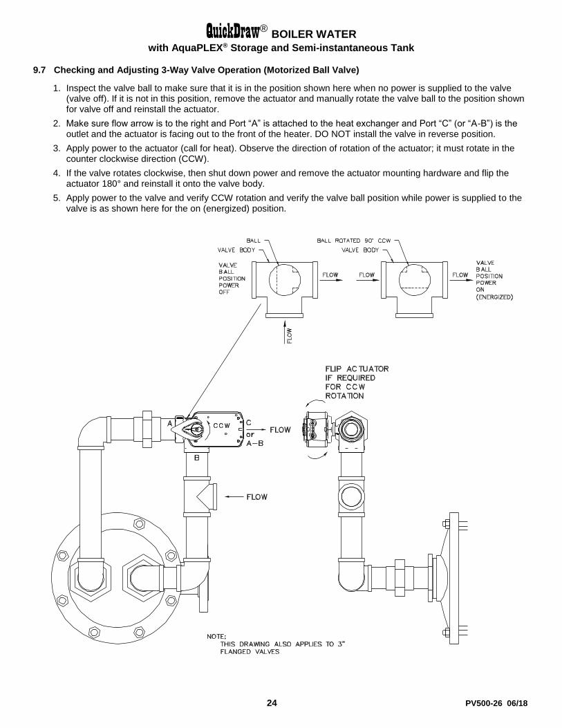
9.7 Checking and Adjusting 3-Way Valve Operation (Motorized Ball Valve)
1. Inspect the valve ball to make sure that it is in the position shown here when no power is supplied to the valve (valve off). If it is not in this position, remove the actuator and manually rotate the valve ball to the position shown for valve off and reinstall the actuator.
2. Make sure flow arrow is to the right and Port “A” is attached to the heat exchanger and Port “C” (or “A-B”) is the outlet and the actuator is facing out to the front of the heater. DO NOT install the valve in reverse position.
3. Apply power to the actuator (call for heat). Observe the direction of rotation of the actuator; it must rotate in the counter clockwise direction (CCW).
4. If the valve rotates clockwise, then shut down power and remove the actuator mounting hardware and flip the actuator 180° and reinstall it onto the valve body.
5. Apply power to the valve and verify CCW rotation and verify the valve ball position while power is supplied to the valve is as shown here for the on (energized) position.
QuickDraw® BOILER WATER
with AquaPLEX® Storage and Semi-instantaneous Tank
25 PV500-26 06/18
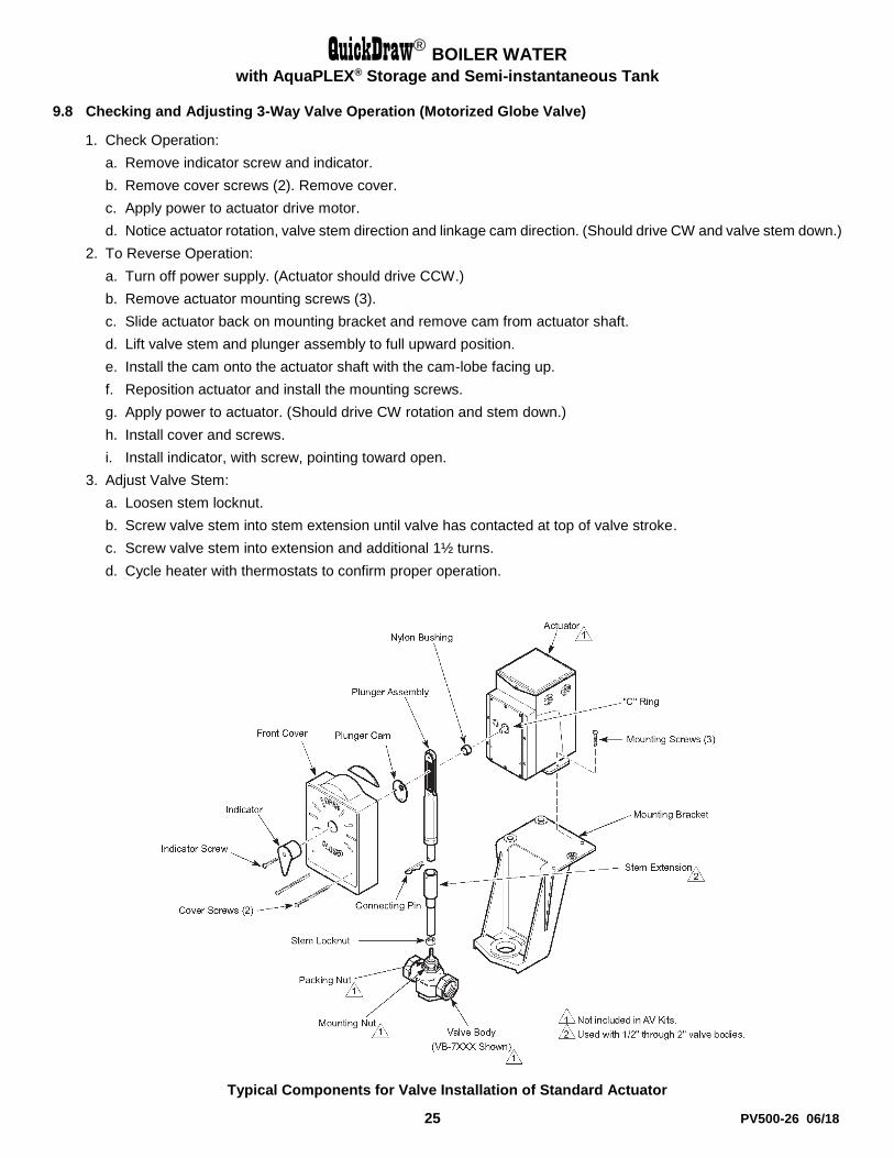
9.8 Checking and Adjusting 3-Way Valve Operation (Motorized Globe Valve)
1. Check Operation:
a. Remove indicator screw and indicator.
b. Remove cover screws (2). Remove cover.
c. Apply power to actuator drive motor.
d. Notice actuator rotation, valve stem direction and linkage cam direction. (Should drive CW and valve stem down.)
2. To Reverse Operation:
a. Turn off power supply. (Actuator should drive CCW.)
b. Remove actuator mounting screws (3).
c. Slide actuator back on mounting bracket and remove cam from actuator shaft.
d. Lift valve stem and plunger assembly to full upward position.
e. Install the cam onto the actuator shaft with the cam-lobe facing up.
f. Reposition actuator and install the mounting screws.
g. Apply power to actuator. (Should drive CW rotation and stem down.)
h. Install cover and screws.
i. Install indicator, with screw, pointing toward open.
3. Adjust Valve Stem:
a. Loosen stem locknut.
b. Screw valve stem into stem extension until valve has contacted at top of valve stroke.
c. Screw valve stem into extension and additional 1½ turns.
d. Cycle heater with thermostats to confirm proper operation.
Typical Components for Valve Installation of Standard Actuator

QuickDraw® BOILER WATER
with AquaPLEX® Storage and Semi-instantaneous Tank
26 PV500-26 06/18
9.9 Recommended Maintenance Schedule
1. Annual Maintenance
a. Check all joints and pipe connections for tightness, corrosion or deterioration.
b. Check all safety controls and devices including thermostats for proper operation.
c. Check safety shut-off valves for operation and tightness.
d. Test high limit and operating temperature controls.
2. Semi-Annually
a. Recalibrate all indicating and recording gauges.
b. Check piping and wiring of all interlocks and shutoff valves.
3. Monthly Maintenance
a. Test low-water cutoff device and alarm (if equipped).
b. Check gauges, monitors, and indicators.
c. Check instrument and equipment settings.
4. As Required
a. Tank flush and cleanout.
QuickDraw® BOILER WATER
with AquaPLEX® Storage and Semi-instantaneous Tank
27 PV500-26 06/18
10 TROUBLESHOOTING NOTES
Problem 1: Outlet water temperature not constant
a. Cause: Insufficient recovery.
Solution: Check and be sure heater design rating is not being exceeded.
b. Cause: Malfunctioning or misadjusted thermostat(s).
Solution: If the thermostat or controller is always open, then the outlet temperature will vary with load. Measure the tank temperature near the thermostat and compare to setpoint. The thermostat should turn on and off within 5°F of setpoint. Replace if necessary.
Problem 2: Heater recovery is slow or outlet temperature is below setpoint:
c. Cause: The temperature control valve is not opening properly.
Solution: Check for proper operation of valve actuator and linkage. Replace if necessary.
d. Cause: Return water not draining; water drain line is restricted; water check valve is leaking or have failed.
Solution: Reconfigure water return piping and check valve to allow for proper drainage. Check for restriction in the water drain line.
e. Cause: Heat exchanger is breached.
Solution: Shut off the boiler water supply. Residual flow should stop after a short period of time. If the flow continues, water is leaking from the tank into the coil. Disassemble, inspect, repair or replace as required following the instructions in this manual.
f. Cause: Heat exchanger is fouled.
Solution: Inspect the heat exchanger for excessive scaling or fouling on the water side.
g. Cause: Abnormal operating conditions.
Solution: The water temperature has a significant effect on the efficiency of the heat exchanger. Check if the setpoint is higher than specified. Confirm the measured flow rate with meters or by volume and rate. Check that there are no other loads on the heater.
Problem 3: No hot water even at low flow:
h. Cause: Control valve not opening.
Solution: Check that electrical coils are energized. If not, trace wiring problem. If so, the valve may be faulty, the boiler water flow and temperature is inadequate, or the linkage (if applicable) is out of adjustment.
i. Cause: The high-temperature limit is open.
Solution: Check the individual components of the system and repair or replace the failed component(s) as necessary.
Problem 4: Outlet temperature is too high:
j. Cause: Malfunctioning or misadjusted thermostat(s).
Solution: Check thermostat setting. Measure the tank temperature near the thermostat and compare to setpoint. The thermostat should turn on and off within 5°F of setpoint. Replace if necessary.
k. Cause: The control valve is not closing properly.
Solution: See the adjustment instructions in this manual or for the specific temperature control valve assembly installed. Replace worn components as required.
Problem 5: Heat exchanger visibly leaking.
l. Cause: Plumbing connection loose.
Solution: Check and tighten plumbing connection.
m. Cause: Double-wall heat exchanger tube leak.
Solution: If one of the tube walls is breached, a double-wall heat exchanger will leak at the joint between the tubesheets. Isolate the heater and replace the heat exchanger.

QuickDraw® BOILER WATER
with AquaPLEX® Storage and Semi-instantaneous Tank
28 PV500-26 06/18
Since PVI cannot control the use of the appliance, water conditions, or maintenance, the warranty on the heat exchanger does not cover poor performance, structural failure, or leaking due to an excessive accumulation of scale
MODEL NUMBER:
SERIAL NUMBER:
INSTALLATION DATE:
PVI Industries, LLC 3209 Galvez Ave. Fort Worth, TX 76111 1-800-433-5654 www.pvi.com