Embed Size (px)
Citation preview

Manual 2100-514APage 1 of 15
Models:ERVF-A2ERVF-C2
WALL MOUNTENERGY RECOVERY VENTILATOR
WITH EXHAUST
For Use With Bard1-1/2 Through 2 Ton
Wall Mount™ Air Conditionersand Heat Pumps
INSTALLATION INSTRUCTIONS
Manual: 2100-514ASupersedes: 2100-514File: Volume III, Tab 19Date: 03-09-10
Bard Manufacturing Company, Inc.Bryan, OH 43506
Since 1914. . .Moving ahead, just as planned.

Manual 2100-514APage 2 of 15
CONTENTS
Model Nomenclature Legend .................................... 3
Electrical Specifications ............................................ 3
General Description .................................................. 3
General Information .................................................. 3
Unpacking ................................................................. 3
Performance and Application Data ............................ 4
Basic Installation (Field Installation) ......................... 5
Basic Installation (Factory Installed Models) ............. 6
Control Wiring ......................................................... 12
Control Requirements ............................................. 12
Recommended Control Sequences ........................ 12
Ventilation Airflow .................................................... 12
Energy Recovery Ventilator Maintenance ............... 13
Maintenance Procedures ................................ 13 & 14
Annual Maintenance ............................................... 14
Figures
Figure 1 Removing Access Panels ..................... 6
Figure 2 Removing Filter & Grille ........................ 7
Figure 3 Running Wiring ..................................... 8
Figure 4 Control Panel ........................................ 9
Figure 5 Replacing Access Panel ..................... 10
Figure 6 Airflow Diagram .................................. 11
Figure 6A Speed Tap Label ................................. 11
Figure 7 Belt Replacement ............................... 14
Figure 8 Hub Assembly ..................................... 15
Tables
Table 1 Ventilation Air (CFM) ........................... 12
BARD MANUFACTURING COMPANYBRYAN, OHIO USA 43506

Manual 2100-514A
Page 3 of 15
MODEL NOMENCLATURE LEGEND
GENERAL INFORMATION
The ventilator should only be installed by a trained heating
and air conditioning technician. These instructions serve
as a guide to the technician installing the ventilator
package. They are not intended as a step-by-step
procedure, with which the mechanically-inclined owner
can install the package.
The ventilator housing is shipped in one carton, which
contains the following:
1. Energy Recovery Ventilator
2. Service Door
3. Rain Hood and Mist Eliminator
4. Installation Instructions
UNPACKING
Upon receipt of the equipment, be sure to compare the
model number found on the shipping label with the
accessory identification information on the ordering and
shipping document to verify that the correct accessory has
been shipped.
Inspect the carton housing of each ventilator as it is
received, and before signing the freight bill, verify that all
items have been received and that there is no visible
damage. Note any shortages or damage on all copies of
the freight bill. The receiving party must contact the last
carrier immediately, preferably in writing, requesting
inspection by the carrier’s agent. Concealed damage not
discovered until after loading must be reported to the
carrier within 15 days of its receipt.
GENERAL DESCRIPTION
The Wall Mount Energy Recovery Ventilator was
designed to provide energy efficient, cost effective
ventilation to meet I.A.Q. (Indoor Air Quality)
requirements while still maintaining good indoor comfort
and humidity control for a variety of applications such as
schools, classrooms, lounges, conference rooms, beauty
salons and others. It provides a constant supply of fresh
air for control of airborne pollutants including CO2, smoke,
radon, formaldehyde, excess moisture, virus and bacteria.
The ventilator incorporates patented rotary heat exchanger
to remove both heat and moisture.
It is designed as a single package which can be easily
factory or field installed for new installations or retrofit to
the new Bard W**A and W**H series wall mounted units.
The package consists of a unique rotary Energy Recovery
Cassette that can be easily removed for cleaning or
maintenance. The ERVF-*2 has one 13-inch wheel for
efficient heat transfer. The heat transfer wheels use a
permanently bonded dry desiccant coating for total heat
recovery.
Ventilation is accomplished with (2) blower/motor
assemblies each consisting of a drive motor and dual
blowers for maximum ventilation at low sound levels. Air
is exhausted at the same rate that fresh air is brought into
the structure, thus not pressuring the building. The
rotating energy wheels provide the heat transfer effectively
during both summer and winter conditions. Provides
required ventilation to meet the requirements of ASHRAE
62.1 standard.
ELECTRICAL SPECIFICATIONS
ledoM egatloV spmAlortnoC
egatloV
2A-FVRE 802/032 2.2 V42
2C-FVRE 064 2.1 V42
NOTE: During operation below 5 degrees F outdoor
temperature, freezing of moisture in the heat
transfer wheel can occur. Consult the factory if
this possibility exists.
Energy Recovery Ventilator
ERV F — A 2
Wall Mount™ – Cabinet Size
2 = W18-24A, L and H
3 = W30-36A, L and H
5 = W42-60A, L and H
ELECTRICAL
A = 230/208 VOLT
B = 230/208 VOLT
C = 460 VOLT2-PIECE FRONT DOOR

Manual 2100-514A
Page 4 of 15
LEGEND:
VLT = Ventilation Load – Total
VLS = Ventilation Load – Sensible
VLL = Ventilation Load – Latent
HRT = Heat Recover – Total
HRS = Heat Recovery – Sensible
HRL = Heat Recovery – Latent
WVL = Winter Ventilation Load
WHR = Winter Heat Recovery
PERFORMANCE AND APPLICATION DATA – ERVF-*2
SUMMER COOLING PERFORMANCE
(INDOOR DESIGN CONDITIONS 75°DB/62°WB)
tneibmA.D.O
�ETARNOITALITNEV 052 MFCycneiciffE%26
�ETARNOITALITNEV 522 MFCycneiciffE%36
2�ETARNOITALITNEV 0 MFC0ycneiciffE%36
F�BW/BD TLV SLV LLV TRH SRT LRH TLV SLV LLV TRH SRH LRH TLV SLV LLV TRH SRH LRH
570756
5291100180018
0018523100
493722052205
220522800
7270178277827
7827144300
857619541954
1954861200
045908460846
0846060300
010628042804
2804829100
0857075606
0557152911368605760576
0576
00801571531100
188014937552458145814
5814
696690230700
8875172701371627062706
2706
6179556410100
64998576988362836283
6283
121633924600
040410459094500450045
0045
046804140900
54880106854320432043
2043
344580626500
0857075606
0557152911368600450045
0045
051215256364100
188014937552484338433
8433
3357640470900
8875172701371685848584
8584
039010785513100
64998576988306030603
0603
6886896392800
040410459094502340234
0234
02790225071100
54880106854322722272
2272
4216982373700
0857075606
0557152911368605040504
0504
005315787318200
188014937552411521152
1152
07383884447100
8875172701371634633463
3463
541214807035200
64998576988359225922
5922
15673644495100
040410459094504230423
0423
008010036052200
54880106854314021402
1402
40869693714100
0857075606
0557152911386600720072
0072
058415229361400
188014937552447614761
4761
70290275185200
8875172701371692429242
9242
953318928447300
64998576988303510351
0351
61488225953200
040410459094506120612
0612
088110837003300
54880106854316311631
1631
48479464890200
57075606
52911368636320531
0531
57501315531010
493755245641738
738
755681438260
72701371652124121
4121
315995941190
857698839331567
567
399542134750
0459094509810801
0801
064801440180
010685430911086
086
033587720150
075606
368636320
0368636320
552456410
0552456410
371652120
0371652120
988693310
0988393310
094509810
0094509810
854309110
0854309110
WINTER HEATING PERFORMANCE
(INDOOR DESIGN CONDITIONS 70° F DB)
tneibmA.D.O
ETARNOITALITNEV
ffE%47MFC052 ffE%57MFC522 ffE%57MFC002
F�BD LVW RHW LVW RHW LVW RHW
56 0531 999 4121 119 0801 018
06 0072 8991 9242 2281 0612 0261
55 0504 7992 3463 3372 0423 0342
05 0045 6993 8584 3463 0234 0423
54 0576 5994 2706 4554 0045 0504
04 0018 4995 7827 5645 0846 0684
53 0549 3996 1058 6736 0657 0765
03 00801 2997 6179 7827 0468 0846
52 05121 1998 03901 8918 0279 0927
02 00531 0999 54121 8019 00801 0018
51 05841 98901 95331 91001 08811 0198
105
100
95
90
85
80
75

Manual 2100-514A
Page 5 of 15
BASIC INSTALLATION(FIELD INSTALLATION)
1. Unpack the ventilator assembly, which includes
the integral ventilator with attached electrical
harness and miscellaneous hardware.
CAUTIONBe sure the correct model and voltage EnergyRecovery Ventilator is used with the correct airconditioner or heat pump to insure correctvoltage compatibility.
WARNINGOpen and lock unit disconnect switch beforeinstalling this accessory to prevent injury ordeath due to electrical shock or contact withmoving parts. Turn thermostat to OFF.
2. Remove the existing exterior blower access, filter
access and vent access panels on the Bard Wall Mount
unit. Save the blower access and filter access panels
and discard vent option access panel. (See Figure 1.)
3. Remove and save existing unit return air filter and left
side filter support bracket by removing two screws
from left side of unit. Remove and save top four (4)
screws from front grille. (See Figure 2.)
4. Remove and discard the exhaust cover plate.
(See Figure 2.)
5. Install ventilator by inserting the ventilator into the
unit to the far left side clearing the right filter bracket.
Once the ventilator is fully inserted, slide the ventilator
to the right until it is tight against the back of the
control panel. (See Figure 3.)
IMPORTANT NOTE: Position front lip of ventilator
under front grille and on top of condenser
partition. (See Figure 3 inset.) This is important
to insure proper drainage of any water entering
damper assembly.
6. Open control panel to gain access to unit low voltage
terminal block. (Insure all power is OFF prior to
opening the control panel.)
7. Route four (4) low voltage electrical leads through the
7/8" bushing in control panel (Figure 3) into low
voltage box.
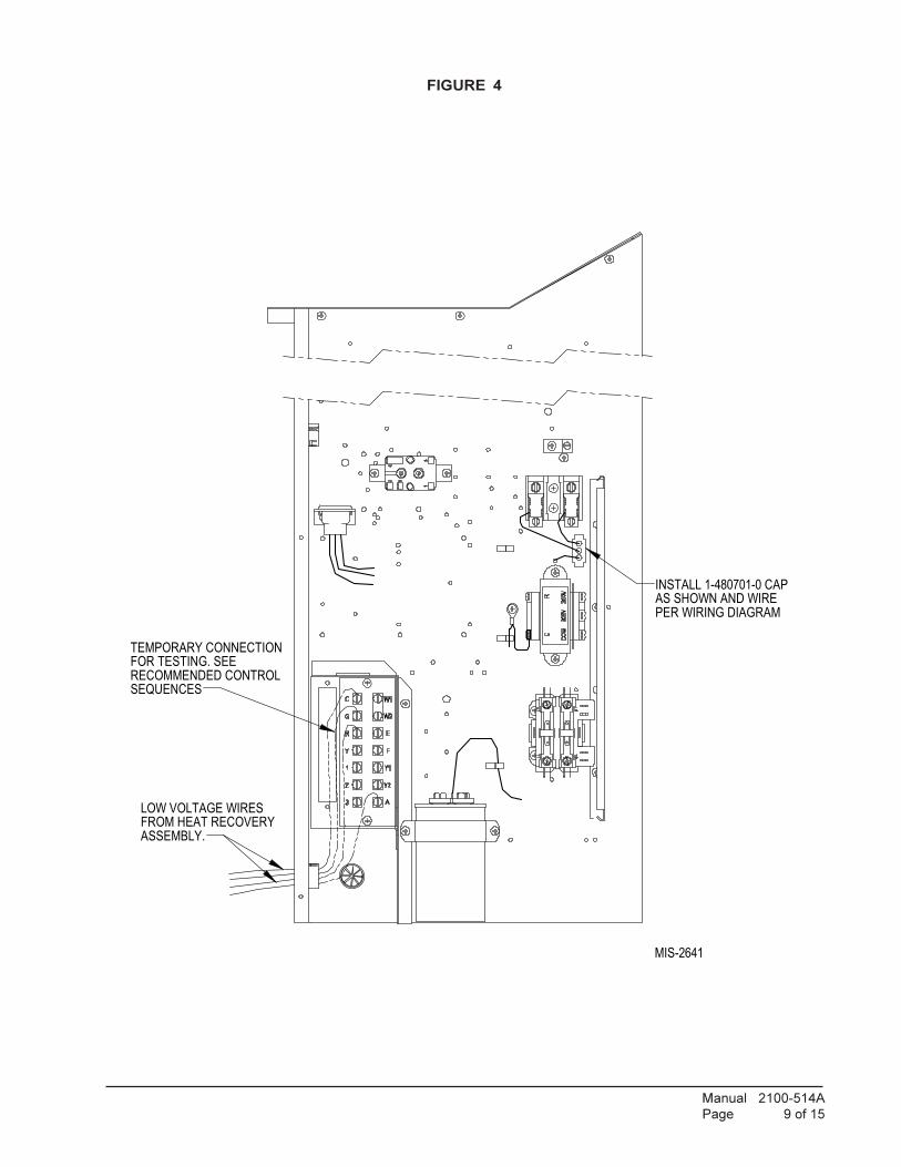
8. Temporarily connect leads with fork terminal to
corresponding points on terminal strip to terminals C,
R, G and A or O1 depending whether a heat pump or
air conditioner. (See Figure 4.)
NOTE: These 24 volt control wires control the
starting and stopping of the Energy Recovery
Ventilator and can be independently controlled by an
energy management control or timer. See separate
section on Control Wiring.
9. Remove female plug of high voltage wiring harness
from the heat recover assembly and snap into unit
control panel from the inside of the control panel in the
hole provided. Wire to terminal block. (See Figure 4
and wiring diagram.)
10. Plug male plug from ERVF assembly into female
connector at back of control panel. (See Figures 3 & 4.)
11. Replace inner and outer control panel cover.
12. Ventilator checkout
A. Resupply power to unit.
B. Energize the evaporator blower by
switching thermostat to the manual fan
position with Heat/Cool in OFF position.
C. Ventilator heat transfer wheels should rotate
slowly (49 RPM). Intake and exhaust
blowers should run.
D. De-energize the evaporator blower. Energy
recovery heat transfer wheels and fresh air
and exhaust air blowers should stop.
E. This completes ventilator checkout.
14. Disconnect the wires temporarily connected in
Step 8.
15. Reinstall the blower access and filter access panels at
top of unit and secure with sheet metal screws.
16. Replace the vent option access panel with the new
panel provided. Attach air intake hood with screws
provided. (See Figure 5.) Be sure to insert the top
flange of the air intake hood into and through the slot
in the service door and between the door and insulation
to prevent bowing of the door.
17. Apply Certification label, included with Installation
Instructions, next to unit Serial Plate.
18. Ventilator is now ready for operation.
ledoMehthtiWesUroFstinUgniwolloF
lacirtcelE
2A-FVREA-*A81W
B-,A-*A42WA-*H81W
B-,A-*H42W-802/032esahp3ro1
2C-FVRE C-*A42W C-*H42W esahp3-064

Manual 2100-514A
Page 6 of 15
FIGURE 1
REMOVING ACCESS PANELS
BASIC INSTALLATION(FACTORY INSTALLED MODELS)
1. Remove blower access, filter access and vent option
panels. Remove filter bracket from shipping location
and install on left side. Remove filter located above
air circulation blowers. Install filter.
2. Remove air intake hood from shipping location and
install air intake hood on vent option panel. Refer to
the Control Wiring Section for suggested control
schemes. After wiring, replace all panels.
REMOVE & SAVE
REMOVE & DISCARD

Manual 2100-514A
Page 7 of 15
FIGURE 2
REMOVING FILTER AND GRILLE
REMOVE & DISCARD

Manual 2100-514A
Page 8 of 15
FIGURE 3
FIGURE 3 –
INSET
SIDE VIEW -
SEE STEP 5 OF
INSTRUCTIONS
Manual 2100-514A
Page 9 of 15
FIGURE 4
MIS-2641
INSTALL 1-480701-0 CAPAS SHOWN AND WIREPER WIRING DIAGRAM
FROM HEAT RECOVERYASSEMBLY.
LOW VOLTAGE WIRES
TEMPORARY CONNECTION FOR TESTING. SEE RECOMMENDED CONTROL SEQUENCES

Manual 2100-514A
Page 10 of 15
FIGURE 5

Manual 2100-514A
Page 11 of 15
FIGURE 6
FIGURE 6A
Manual 2100-514A
Page 12 of 15
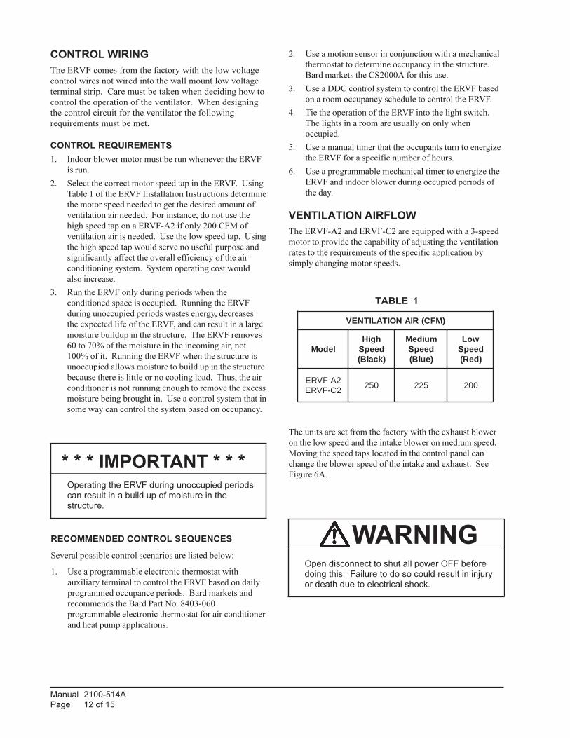
CONTROL WIRING
The ERVF comes from the factory with the low voltage
control wires not wired into the wall mount low voltage
terminal strip. Care must be taken when deciding how to
control the operation of the ventilator. When designing
the control circuit for the ventilator the following
requirements must be met.
CONTROL REQUIREMENTS
1. Indoor blower motor must be run whenever the ERVF
is run.
2. Select the correct motor speed tap in the ERVF. Using
Table 1 of the ERVF Installation Instructions determine
the motor speed needed to get the desired amount of
ventilation air needed. For instance, do not use the
high speed tap on a ERVF-A2 if only 200 CFM of
ventilation air is needed. Use the low speed tap. Using
the high speed tap would serve no useful purpose and
significantly affect the overall efficiency of the air
conditioning system. System operating cost would
also increase.
3. Run the ERVF only during periods when the
conditioned space is occupied. Running the ERVF
during unoccupied periods wastes energy, decreases
the expected life of the ERVF, and can result in a large
moisture buildup in the structure. The ERVF removes
60 to 70% of the moisture in the incoming air, not
100% of it. Running the ERVF when the structure is
unoccupied allows moisture to build up in the structure
because there is little or no cooling load. Thus, the air
conditioner is not running enough to remove the excess
moisture being brought in. Use a control system that in
some way can control the system based on occupancy.
RECOMMENDED CONTROL SEQUENCES
Several possible control scenarios are listed below:
1. Use a programmable electronic thermostat with
auxiliary terminal to control the ERVF based on daily
programmed occupance periods. Bard markets and
recommends the Bard Part No. 8403-060
programmable electronic thermostat for air conditioner
and heat pump applications.
The units are set from the factory with the exhaust blower
on the low speed and the intake blower on medium speed.
Moving the speed taps located in the control panel can
change the blower speed of the intake and exhaust. See
Figure 6A.
WARNINGOpen disconnect to shut all power OFF beforedoing this. Failure to do so could result in injuryor death due to electrical shock.
TABLE 1
)MFC(RIANOITALITNEV
ledoMhgiHdeepS)kcalB(
muideMdeepS)eulB(
woLdeepS)deR(
2A-FVRE2C-FVRE
052 522 002
2. Use a motion sensor in conjunction with a mechanical
thermostat to determine occupancy in the structure.
Bard markets the CS2000A for this use.
3. Use a DDC control system to control the ERVF based
on a room occupancy schedule to control the ERVF.
4. Tie the operation of the ERVF into the light switch.
The lights in a room are usually on only when
occupied.
5. Use a manual timer that the occupants turn to energize
the ERVF for a specific number of hours.
6. Use a programmable mechanical timer to energize the
ERVF and indoor blower during occupied periods of
the day.
VENTILATION AIRFLOW
The ERVF-A2 and ERVF-C2 are equipped with a 3-speed
motor to provide the capability of adjusting the ventilation
rates to the requirements of the specific application by
simply changing motor speeds.
* * * IMPORTANT * * *
Operating the ERVF during unoccupied periodscan result in a build up of moisture in thestructure.

Manual 2100-514A
Page 13 of 15
ENERGY RECOVERY VENTILATORMAINTENANCE
GENERAL INFORMATION
The ability to clean exposed surfaces within air moving
systems is an important design consideration for the
maintenance of system performance and air quality. The
need for periodic cleaning will be a function of operating
schedule, climate, and contaminants in the indoor air being
exhausted and in the outdoor air being supplied to the
building. All components exposed to the airstream,
including energy recovery wheels, may require cleaning in
most applications.
Rotary counterflow heat exchanges (heat wheels) with
laminar airflow are “self-cleaning” with respect to dry
particles. Smaller particles pass through; larger particles
land on the surface and are blown clear as the flow
direction is reversed. For this reason, the primary need for
cleaning is to remove films of oil-based aerosols that have
condensed on energy transfer surfaces. Buildup of material
over time may eventually reduce airflow. Most
importantly, in the case of desiccant coated (enthalpy)
wheels, such films can close off micron sized pores at the
surface of the desiccant material, reducing the efficiency,
with which the desiccant can absorb and desorb moisture.
FREQUENCY
In a reasonably clean indoor environment such as a school,
office building, or home, experience shows that reductions
of airflow or loss of sensible (temperature) effectiveness
may not occur for ten or more years. However, experience
also shows that measurable changes in latent energy (water
vapor) transfer can occur in shorter periods of time in
commercial, institutional and residential applications
experiencing moderate occupant smoking or with cooking
facilities. In applications experiencing unusually high
levels of occupant smoking, such as smoking lounges,
nightclubs, bars and restaurants, washing of energy transfer
surfaces, as frequently as every six months, may be
necessary to maintain latent transfer efficiency. Similar
washing cycles may also be appropriate for industrial
applications involving the ventilation of high levels of
smoke or oil-based aerosols such as those found in welding
or machining operations, for example. In these
applications, latent efficiency losses of as much as 40% or
more may develop over a period of one to three years.
CLEANABILITY AND PERFORMANCE
In order to maintain energy recovery ventilation systems,
energy transfer surfaces must be accessible for washing to
remove oils, grease, tars and dirt that can impede
performance or generate odors. Washing of the desiccant
surfaces is required to remove contaminate buildups that
can reduce adsorption of water molecules. The continued
ability of an enthalpy wheel to transfer latent energy
depends upon the permanence of the bond between the
desiccant and the energy transfer surfaces.
Bard wheels feature silica gel desiccant permanently
bonded to the heat exchange surface without adhesives; the
desiccant will not be lost in the washing process. Proper
cleaning of the Bard energy recovery wheel will restore
latent effectiveness to near original performance.
MAINTENANCE PROCEDURES
NOTE: Local conditions can vary and affect the required
time between routine maintenance procedures,
therefore all sites (or specific units at a site) may
not have the same schedule to maintain acceptable
performance. The following timetables are
recommended and can be altered based on local
experience.
QUARTERLY MAINTENANCE
1. Inspect mist eliminator/prefilter and clean if necessary.
This filter is located in the fresh air intake hood on the
front of the unit. This is an aluminum mesh filter and
can be cleaned with water and any detergent not
harmful to aluminum.
2. Inspect wall mount unit filter and clean or replace as
necessary. This filter is located either in the unit, in a
return air filter grille assembly, or both. If in the unit it
can be accessed by removing the lower service door on
the front of the unit. If in a return air filter grille, by
hinging the grille open to gain access.
3. Inspect energy recovery ventilator for proper wheel
rotation and dirt buildup. This can be done in
conjunction with Item 2 above. Energize the energy
recovery ventilator after inspecting the filter and
observe for proper rotation and/or dirt buildup.
4. Recommended energy recovery wheel cleaning
procedures follow Steps 5 through 8.
5. Disconnect all power to unit. Remove the lower
service door of the wall mount unit to gain access to
the energy recovery ventilator.

Manual 2100-514A
Page 14 of 15
6. Remove the front access panel on the ventilator.
Unplug amp connectors to cassette motors. Slide
energy recovery cassette out of ventilator.
7. Use a shop vacuum with brush attachment to clean
both sides of the energy recovery wheels.
8. Reverse shop vacuum to use as a blower and blow out
any residual dry debris from the wheel.
NOTE: Discoloration and staining of the wheel
does not affect its performance. Only
excessive buildup of foreign material needs
to be removed.
9. If any belt chirping or squealing noise is present, apply
a small amount of LPS-1 or equivalent dry film
lubricant to the belt.
ANNUAL MAINTENANCE
1. Inspect and conduct the same procedures as outlined
under Quarterly Maintenance.
2. To maintain peak latent (moisture) removal capacity, it
is recommended that the energy recovery wheels be
sprayed with a diluted nonacid based evaporator coil
cleaner or alkaline detergent solution such as 409.
NOTE: Do not use acid based cleaners, aromatic solvents,
temperatures in excess of 170°F or steam.
Damage to the wheel may result.
Do not disassemble and immerse the entire heat
wheel in a soaking solution, as bearing and other
damage may result.
3. Rinse wheel thoroughly after application of the
cleaning solution, and allow to drain before
reinstalling.
4. No re-lubrication is required to heat wheel bearings of
the drive motor, or to the intake and exhaust blower
motors.
5. If any belt chirping or squealing noise is present, apply
a small amount of LPS-1 or equivalent dry film
lubricant to the belt.
Belt ReplacementInstructions
MIS-1890
Route this part of replacementbelt in bottom groove of pulley.
Route this part of replacementbelt in top groove of pulley.
If belt "squeaks" or "chirps"lubricate lightly with LPS-1or equivalent "dry film"lubricant.
FIGURE 7
BELT REPLACEMENT INSTRUCTIONS
(2 WHEEL CASSETTE ONLY)

Manual 2100-514A
Page 15 of 15
FIGURE 8
HUB ASSEMBLY WITH BALL BEARINGS