Embed Size (px)
Citation preview
thermofin GmbH, Am Windrad 1, 08468 Heinsdorfergrund Tel.: +49 (0)3765-3800-0
vertical units, status: 2015-09-14 - english translation of the original installation manual - © thermofin GmbH
Installation instructions
vertical units
Series TCV, TCMU, TACV, TACMU,
TOCV, TOCMU, TDV, TDMU
thermofin GmbH, Am Windrad 1, 08468 Heinsdorfergrund Tel.: +49 (0)3765-3800-0
vertical units, status: 2015-09-14 - english translation of the original installation manual - © thermofin GmbH page 2 of 27
1. Preliminary notes ............................................................................................................. 3 1.1 Fundamentals ............................................................................................................................... 3
1.2 Range of application .................................................................................................................... 4 1.3 Standards and directives ............................................................................................................... 4
2. Technical data ................................................................................................................... 5 2.1. Design data .................................................................................................................................. 5 2.2 Application and intended use ....................................................................................................... 5
2.3 Material data ................................................................................................................................ 5 2.4 Sound information........................................................................................................................ 5 2.5 Unit key ........................................................................................................................................ 6 2.6 Data on the type plate ................................................................................................................... 6
3. Safety ................................................................................................................................. 7 3.1 General safety instructions ........................................................................................................... 7
3.2 Safety instructions on the installation site .................................................................................... 7
3.3 Safety instructions on the unit ...................................................................................................... 8 3.4 Safety instructions on the operating supplies ............................................................................... 9
3.4.1 Refrigerants of the group A1 (Freon) ....................................................................................... 9 3.4.2 Ammonia (NH3) ........................................................................................................................ 9 3.4.3 Carbon dioxide (CO2) ............................................................................................................. 10 3.4.4 Ethylene glycol ....................................................................................................................... 12
3.4.5 Water ....................................................................................................................................... 12
4. Transport, storage, positioning, installation ................................................................ 13 4.1 General ....................................................................................................................................... 13
4.2 Transport .................................................................................................................................... 13 4.2.1 Packing .................................................................................................................................... 14
4.3 Storage ....................................................................................................................................... 14 4.4 Lifting and positioning ............................................................................................................... 15
4.5 Installation .................................................................................................................................. 16 4.6 Pipe connection .......................................................................................................................... 17
4.6.1 Characteristics of dry coolers .................................................................................................. 17
5. Fans and electric system ................................................................................................ 18 5.1 Connection and installation ........................................................................................................ 18
5.2 Fans with EC motors .................................................................................................................. 19
5.3 Fans with external rotor motors ................................................................................................. 19
5.4 Fans with standard motors or ATEX motors ............................................................................. 19
5.5 Electrical switching and control mechanisms ............................................................................ 20
5.5.1 Information of speed regulations ............................................................................................ 20
6. Commissioning, normal operation, maintenance, shutdown, disposal ..................... 21 6.1 Commissioning .......................................................................................................................... 21
6.1.1 Return to service after a longer period of standstill ................................................................ 21 6.2 Normal operation ....................................................................................................................... 21 6.2.1 Operation with water spraying system .................................................................................... 22
6.3 Maintenance ............................................................................................................................... 23 6.3.1 Cleaning of the fins ................................................................................................................. 23
6.3.2 Cleaning of the casings ........................................................................................................... 24 6.4 Spare parts .................................................................................................................................. 24 6.5 Shutdown ................................................................................................................................... 24 6.6 Disposal ...................................................................................................................................... 24
7. Inspection- and maintenance plan (recommendation) ............................................... 25
8. Troubleshooting .............................................................................................................. 26
thermofin GmbH, Am Windrad 1, 08468 Heinsdorfergrund Tel.: +49 (0)3765-3800-0
vertical units, status: 2015-09-14 - english translation of the original installation manual - © thermofin GmbH page 3 of 27
1. Preliminary notes
The purpose of assembly and operating manuals is to prevent dangers to persons and to the
environment, which may be caused by a machine and by the work performed in connection with the
machine, particularly during transport, assembly, commissioning and operation of the unit.
Therefore, all points of this manual must be carefully read and observed.
Warranty claims shall be excluded in case of errors and damages resulting from the fact that
prescriptions of this operating manual have not been observed or in case of complaints
resulting from the replacement of parts with non-original parts as well as from
reconstructions or adjustments or modifications of the operating parameters or the
functionality of the unit which have not been authorised explicitly by the manufacturer.
1.1 Fundamentals
The present assembly and operating manual refers to units of the following type series:
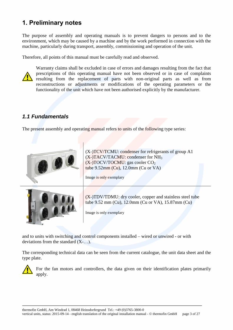
(X-)TCV/TCMU: condenser for refrigerants of group A1
(X-)TACV/TACMU: condenser for NH3
(X-)TOCV/TOCMU: gas cooler CO2
tube 9.52mm (Cu), 12.0mm (Cu or VA)
Image is only exemplary
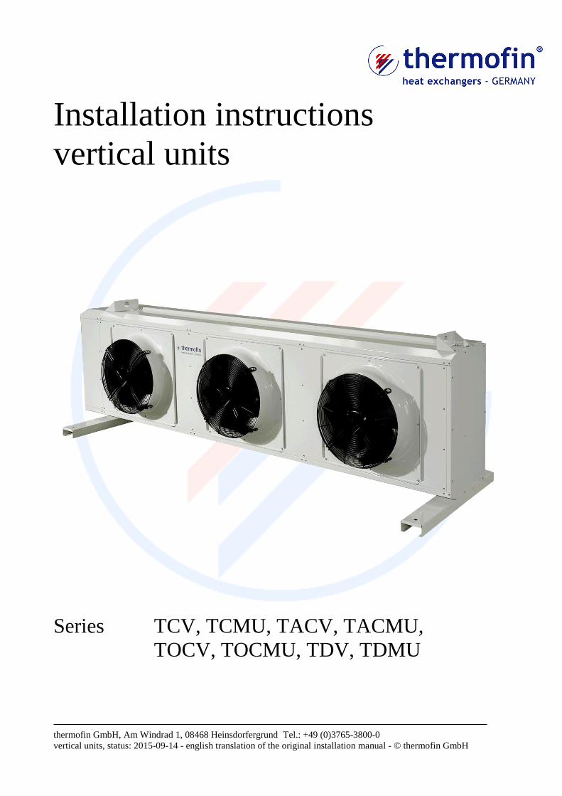
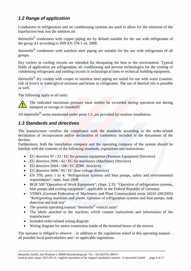
(X-)TDV/TDMU: dry cooler, copper and stainless steel tube
tube 9.52 mm (Cu), 12.0mm (Cu or VA), 15.87mm (Cu) Image is only exemplary
and to units with switching and control components installed – wired or unwired - or with
deviations from the standard (X-…).
The corresponding technical data can be seen from the current catalogue, the unit data sheet and the
type plate.
For the fan motors and controllers, the data given on their identification plates primarily
apply.
thermofin GmbH, Am Windrad 1, 08468 Heinsdorfergrund Tel.: +49 (0)3765-3800-0
vertical units, status: 2015-09-14 - english translation of the original installation manual - © thermofin GmbH page 4 of 27
1.2 Range of application
Condensers in refrigeration and air conditioning systems are used to allow for the emission of the
liquefaction heat into the ambient air.
thermofin® condensers with copper piping are by default suitable for the use with refrigerants of
the group A1 according to DIN EN 378-1 ed. 2008.
thermofin® condensers with stainless steel piping are suitable for the use with refrigerants of all
groups.
Dry coolers in cooling circuits are intended for dissipating the heat to the environment. Typical
fields of application are refrigeration, air conditioning and process technologies for the cooling of
condensing refrigerants and cooling circuits in technological lines or technical building equipment.
thermofin® dry coolers with cooper or stainless steel piping are suited for use with water (caution:
risk of frost!) or water/glycol mixtures and brines as refrigerants. The use of thermal oils is possible
as well.
The following apply to all units:
The indicated maximum pressure must neither be exceeded during operation nor during
transport or storage or standstill!
All thermofin® series mentioned under point 1.1, are provided for outdoor installation.
1.3 Standards and directives
The manufacturer certifies the compliance with the standards according to the order-related
declaration of incorporation and/or declaration of conformity included in the documents of the
devices.
Furthermore, both the installation company and the operating company of the system should be
familiar with the contents of the following standards, regulations and instructions:
EU directive 97 / 23 / EC for pressure equipment (Pressure Equipment Directive)
EU directive 2006 / 42 / EC for machinery (Machinery Directive)
EU directive 2004 / 108 / EC (EMC directive)
EU directive 2006 / 95 / EC (low voltage directive)
EN 378; parts 1 to 4; "Refrigeration systems and heat pumps, safety and environmental
requirements"; state: June 2008
BGR 500 "Operation of Work Equipment"; chapt. 2.35: "Operation of refrigeration systems,
heat pumps and cooling equipment"; applicable in the Federal Republic of Germany
VDMA (German Federation of Machinery and Plant Construction) norm 24243 (08/2005)
“Refrigerating machines and plants, tightness of refrigeration systems and heat pumps, leak
detection and leak test”
The present operating manual "thermofin® vertical units“
The labels attached to the machine, which contain instructions and information of the
manufacturer
Included order-related wiring diagram
Wiring diagram for motor connection inside of the terminal boxes of the motors
The operator is obliged to observe – in addition to the regulations stated in this operating manual –
all possible local particularities and / or applicable regulations.
thermofin GmbH, Am Windrad 1, 08468 Heinsdorfergrund Tel.: +49 (0)3765-3800-0
vertical units, status: 2015-09-14 - english translation of the original installation manual - © thermofin GmbH page 5 of 27
2. Technical data
2.1. Design data
The design data of the unit are shown in the respective order documents and/or the unit data sheet.
It can also be requested from factory by indicating the project or serial number (see type plate).
2.2 Application and intended use
The unit as incomplete machine according to Machinery Directive 2006/42/EC is intended for the
installation in cooling systems. Despite meeting the requirements of intended use and handling the
machine properly, residual risks cannot be completely prevented.
In principle, the unit is suitable for external installation.
The unit may only be used in places where the materials applied are not affected by the surrounding
atmosphere or the medium flowing inside.
Any case of application differing from the one described above requires consultation with the
manufacturer.
The manufacturer does not assume liability for any damages resulting from the non-compliance
with these provisions.
The unit may not be put into operation until the conformity of the complete system has been
declared!
2.3 Material data
Tubes: made of copper or stainless steel, copper tubes inner-grooved in case of condensers
The tube systems are hard soldered or welded.
Fins: made of aluminium with or without coating, AlMg with or without coating or copper
Casing: galvanised steel, powder coated, UV and corrosion resistant
2.4 Sound information
The sound pressure stated was determined by calculation according to DIN EN 13487 and indicates
the average value of the sound pressure on the entire enveloping surface at the defined distance.
thermofin GmbH, Am Windrad 1, 08468 Heinsdorfergrund Tel.: +49 (0)3765-3800-0
vertical units, status: 2015-09-14 - english translation of the original installation manual - © thermofin GmbH page 6 of 27
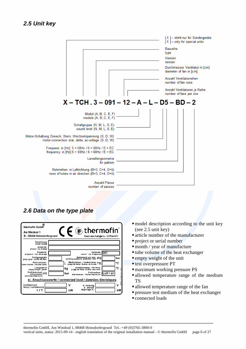
2.5 Unit key
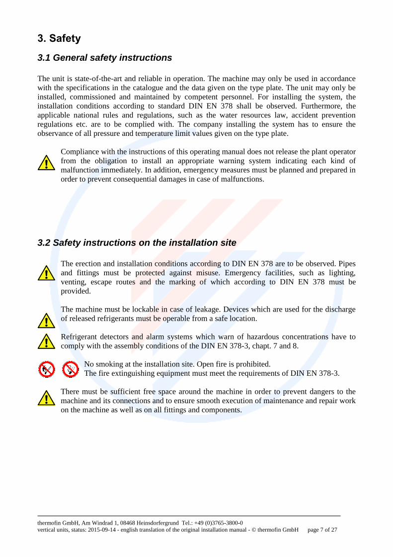
2.6 Data on the type plate
model description according to the unit key
(see 2.5 unit key)
article number of the manufacturer
project or serial number
month / year of manufacture
tube volume of the heat exchanger
empty weight of the unit
test overpressure PT
maximum working pressure PS
allowed temperature range of the medium
TS
allowed temperature range of the fan
pressure test medium of the heat exchanger
connected loads
thermofin GmbH, Am Windrad 1, 08468 Heinsdorfergrund Tel.: +49 (0)3765-3800-0
vertical units, status: 2015-09-14 - english translation of the original installation manual - © thermofin GmbH page 7 of 27
3. Safety
3.1 General safety instructions
The unit is state-of-the-art and reliable in operation. The machine may only be used in accordance
with the specifications in the catalogue and the data given on the type plate. The unit may only be
installed, commissioned and maintained by competent personnel. For installing the system, the
installation conditions according to standard DIN EN 378 shall be observed. Furthermore, the
applicable national rules and regulations, such as the water resources law, accident prevention
regulations etc. are to be complied with. The company installing the system has to ensure the
observance of all pressure and temperature limit values given on the type plate.
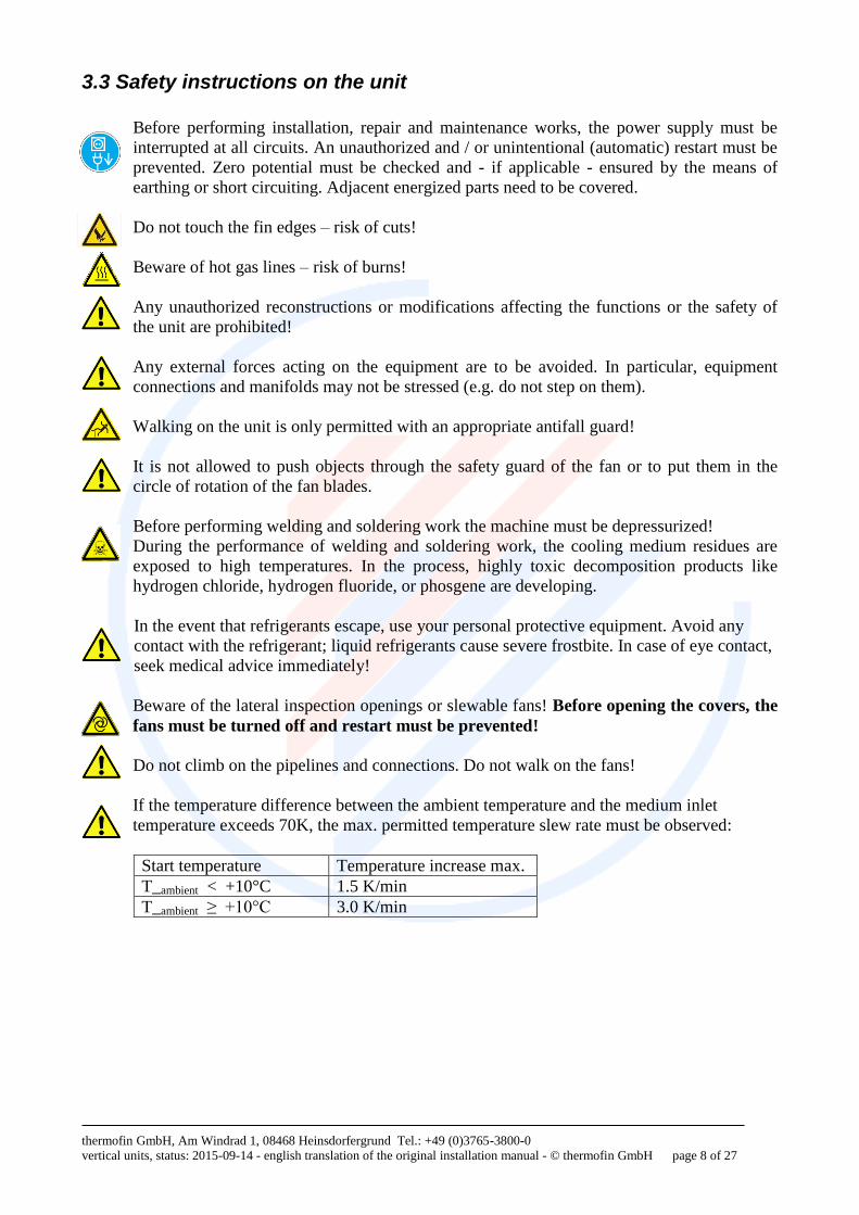
Compliance with the instructions of this operating manual does not release the plant operator
from the obligation to install an appropriate warning system indicating each kind of
malfunction immediately. In addition, emergency measures must be planned and prepared in
order to prevent consequential damages in case of malfunctions.
3.2 Safety instructions on the installation site
The erection and installation conditions according to DIN EN 378 are to be observed. Pipes
and fittings must be protected against misuse. Emergency facilities, such as lighting,
venting, escape routes and the marking of which according to DIN EN 378 must be
provided.
The machine must be lockable in case of leakage. Devices which are used for the discharge
of released refrigerants must be operable from a safe location.
Refrigerant detectors and alarm systems which warn of hazardous concentrations have to
comply with the assembly conditions of the DIN EN 378-3, chapt. 7 and 8.
No smoking at the installation site. Open fire is prohibited.
The fire extinguishing equipment must meet the requirements of DIN EN 378-3.
There must be sufficient free space around the machine in order to prevent dangers to the
machine and its connections and to ensure smooth execution of maintenance and repair work
on the machine as well as on all fittings and components.
thermofin GmbH, Am Windrad 1, 08468 Heinsdorfergrund Tel.: +49 (0)3765-3800-0
vertical units, status: 2015-09-14 - english translation of the original installation manual - © thermofin GmbH page 8 of 27
3.3 Safety instructions on the unit
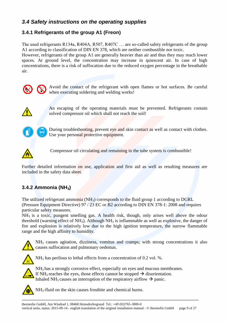
Before performing installation, repair and maintenance works, the power supply must be
interrupted at all circuits. An unauthorized and / or unintentional (automatic) restart must be
prevented. Zero potential must be checked and - if applicable - ensured by the means of
earthing or short circuiting. Adjacent energized parts need to be covered.
Do not touch the fin edges – risk of cuts!
Beware of hot gas lines – risk of burns!
Any unauthorized reconstructions or modifications affecting the functions or the safety of
the unit are prohibited!
Any external forces acting on the equipment are to be avoided. In particular, equipment
connections and manifolds may not be stressed (e.g. do not step on them).
Walking on the unit is only permitted with an appropriate antifall guard!
It is not allowed to push objects through the safety guard of the fan or to put them in the
circle of rotation of the fan blades.
Before performing welding and soldering work the machine must be depressurized!
During the performance of welding and soldering work, the cooling medium residues are
exposed to high temperatures. In the process, highly toxic decomposition products like
hydrogen chloride, hydrogen fluoride, or phosgene are developing.
In the event that refrigerants escape, use your personal protective equipment. Avoid any
contact with the refrigerant; liquid refrigerants cause severe frostbite. In case of eye contact,
seek medical advice immediately!
Beware of the lateral inspection openings or slewable fans! Before opening the covers, the
fans must be turned off and restart must be prevented!
Do not climb on the pipelines and connections. Do not walk on the fans!
If the temperature difference between the ambient temperature and the medium inlet
temperature exceeds 70K, the max. permitted temperature slew rate must be observed:
Start temperature Temperature increase max.
T_ambient < +10°C 1.5 K/min
T_ambient ≥ +10°C 3.0 K/min
thermofin GmbH, Am Windrad 1, 08468 Heinsdorfergrund Tel.: +49 (0)3765-3800-0
vertical units, status: 2015-09-14 - english translation of the original installation manual - © thermofin GmbH page 9 of 27
3.4 Safety instructions on the operating supplies
3.4.1 Refrigerants of the group A1 (Freon)
The used refrigerants R134a, R404A, R507, R407C … are so-called safety refrigerants of the group
A1 according to classification of DIN EN 378, which are neither combustible nor toxic.
However, refrigerants of the group A1 are generally heavier than air and thus they may reach lower
spaces. At ground level, the concentration may increase in quiescent air. In case of high
concentrations, there is a risk of suffocation due to the reduced oxygen percentage in the breathable
air.
Avoid the contact of the refrigerant with open flames or hot surfaces. Be careful
when executing soldering and welding works!
An escaping of the operating materials must be prevented. Refrigerants contain
solved compressor oil which shall not reach the soil!
During troubleshooting, prevent eye and skin contact as well as contact with clothes.
Use your personal protective equipment.
Compressor oil circulating and remaining in the tube system is combustible!
Further detailed information on use, application and first aid as well as resulting measures are
included in the safety data sheet.
3.4.2 Ammonia (NH3)
The utilized refrigerant ammonia (NH3) corresponds to the fluid group 1 according to DGRL
(Pressure Equipment Directive) 97 / 23 EC or B2 according to DIN EN 378-1: 2008 and requires
particular safety measures.
NH3 is a toxic, pungent smelling gas. A health risk, though, only arises well above the odour
threshold (warning effect of NH3). Although NH3 is inflammable as well as explosive, the danger of
fire and explosion is relatively low due to the high ignition temperature, the narrow flammable
range and the high affinity to humidity.
NH3 causes agitation, dizziness, vomitus and cramps; with strong concentrations it also
causes suffocation and pulmonary oedemas.
NH3 has perilous to lethal effects from a concentration of 0.2 vol. %.
NH3 has a strongly corrosive effect, especially on eyes and mucous membranes.
If NH3 reaches the eyes, those effects cannot be stopped disorientation.
Inhaled NH3 causes an interruption of the respiratory airflow panic.
NH3-fluid on the skin causes frostbite and chemical burns.
thermofin GmbH, Am Windrad 1, 08468 Heinsdorfergrund Tel.: +49 (0)3765-3800-0
vertical units, status: 2015-09-14 - english translation of the original installation manual - © thermofin GmbH page 10 of 27
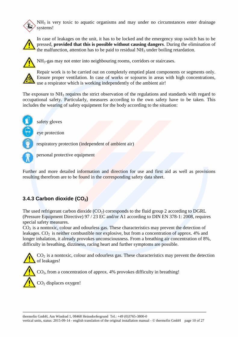
NH3 is very toxic to aquatic organisms and may under no circumstances enter drainage
systems!
In case of leakages on the unit, it has to be locked and the emergency stop switch has to be
pressed, provided that this is possible without causing dangers. During the elimination of
the malfunction, attention has to be paid to residual NH3 under boiling retardation.
NH3-gas may not enter into neighbouring rooms, corridors or staircases.
Repair work is to be carried out on completely emptied plant components or segments only.
Ensure proper ventilation. In case of works or sojourns in areas with high concentrations,
use a respirator which is working independently of the ambient air!
The exposure to NH3 requires the strict observation of the regulations and standards with regard to
occupational safety. Particularly, measures according to the own safety have to be taken. This
includes the wearing of safety equipment for the body according to the situation:
safety gloves
eye protection
respiratory protection (independent of ambient air)
personal protective equipment
Further and more detailed information and direction for use and first aid as well as provisions
resulting therefrom are to be found in the corresponding safety data sheet.
3.4.3 Carbon dioxide (CO2)
The used refrigerant carbon dioxide (CO2) corresponds to the fluid group 2 according to DGRL
(Pressure Equipment Directive) 97 / 23 EC and/or A1 according to DIN EN 378-1: 2008, requires
special safety measures.
CO2 is a nontoxic, colour and odourless gas. These characteristics may prevent the detection of
leakages. CO2 is neither combustible nor explosive, but from a concentration of approx. 4% and
longer inhalation, it already provokes unconsciousness. From a breathing air concentration of 8%,
difficulty in breathing, dizziness, racing heart and further symptoms are possible.
CO2 is a nontoxic, colour and odourless gas. These characteristics may prevent the detection
of leakages!
CO2, from a concentration of approx. 4% provokes difficulty in breathing!
CO2 displaces oxygen!
thermofin GmbH, Am Windrad 1, 08468 Heinsdorfergrund Tel.: +49 (0)3765-3800-0
vertical units, status: 2015-09-14 - english translation of the original installation manual - © thermofin GmbH page 11 of 27
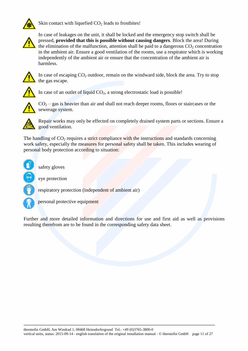
Skin contact with liquefied CO2 leads to frostbites!
In case of leakages on the unit, it shall be locked and the emergency stop switch shall be
pressed, provided that this is possible without causing dangers. Block the area! During
the elimination of the malfunction, attention shall be paid to a dangerous CO2 concentration
in the ambient air. Ensure a good ventilation of the rooms, use a respirator which is working
independently of the ambient air or ensure that the concentration of the ambient air is
harmless.
In case of escaping CO2 outdoor, remain on the windward side, block the area. Try to stop
the gas escape.
In case of an outlet of liquid CO2, a strong electrostatic load is possible!
CO2 – gas is heavier than air and shall not reach deeper rooms, floors or staircases or the
sewerage system.
Repair works may only be effected on completely drained system parts or sections. Ensure a
good ventilation.
The handling of CO2 requires a strict compliance with the instructions and standards concerning
work safety, especially the measures for personal safety shall be taken. This includes wearing of
personal body protection according to situation:
safety gloves
eye protection
respiratory protection (independent of ambient air)
personal protective equipment
Further and more detailed information and directions for use and first aid as well as provisions
resulting therefrom are to be found in the corresponding safety data sheet.
thermofin GmbH, Am Windrad 1, 08468 Heinsdorfergrund Tel.: +49 (0)3765-3800-0
vertical units, status: 2015-09-14 - english translation of the original installation manual - © thermofin GmbH page 12 of 27
3.4.4 Ethylene glycol
Ethylene glycol is a colourless, slightly viscous, slightly volatile and hygroscopic liquid that can be
mixed with water. It has a sweetish smell and taste.
Ethylene glycol vapours are heavier than air and thus they may reach lower spaces. At ground level,
the concentration may increase in quiescent air. In case of high concentrations, there is a risk of
suffocation due to the reduced oxygen percentage in the breathable air.
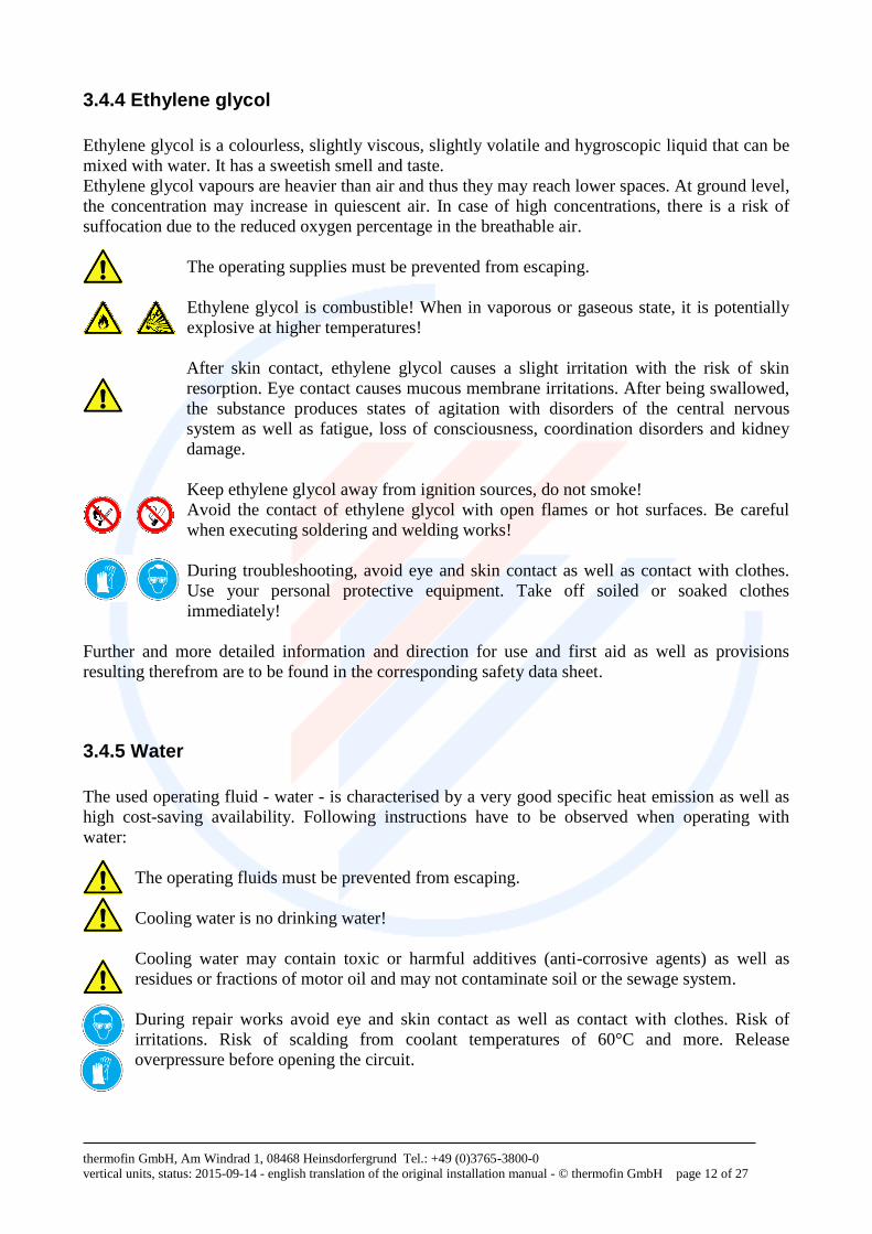
The operating supplies must be prevented from escaping.
Ethylene glycol is combustible! When in vaporous or gaseous state, it is potentially
explosive at higher temperatures!
After skin contact, ethylene glycol causes a slight irritation with the risk of skin
resorption. Eye contact causes mucous membrane irritations. After being swallowed,
the substance produces states of agitation with disorders of the central nervous
system as well as fatigue, loss of consciousness, coordination disorders and kidney
damage.
Keep ethylene glycol away from ignition sources, do not smoke!
Avoid the contact of ethylene glycol with open flames or hot surfaces. Be careful
when executing soldering and welding works!
During troubleshooting, avoid eye and skin contact as well as contact with clothes.
Use your personal protective equipment. Take off soiled or soaked clothes
immediately!
Further and more detailed information and direction for use and first aid as well as provisions
resulting therefrom are to be found in the corresponding safety data sheet.
3.4.5 Water
The used operating fluid - water - is characterised by a very good specific heat emission as well as
high cost-saving availability. Following instructions have to be observed when operating with
water:
The operating fluids must be prevented from escaping.
Cooling water is no drinking water!
Cooling water may contain toxic or harmful additives (anti-corrosive agents) as well as
residues or fractions of motor oil and may not contaminate soil or the sewage system.
During repair works avoid eye and skin contact as well as contact with clothes. Risk of
irritations. Risk of scalding from coolant temperatures of 60°C and more. Release
overpressure before opening the circuit.
thermofin GmbH, Am Windrad 1, 08468 Heinsdorfergrund Tel.: +49 (0)3765-3800-0
vertical units, status: 2015-09-14 - english translation of the original installation manual - © thermofin GmbH page 13 of 27
4. Transport, storage, positioning, installation
4.1 General
The unit may only be installed, integrated in a refrigeration system, operated, maintained and
repaired by qualified personnel of specialist companies according to the definitions of expertise
from DIN EN 378.
During production and before delivery, each unit is subjected to comprehensive quality
testing. The unit is provided in good order and condition. With delivery and before
assembly, the unit must be checked for damages (damages in transit).
4.2 Transport
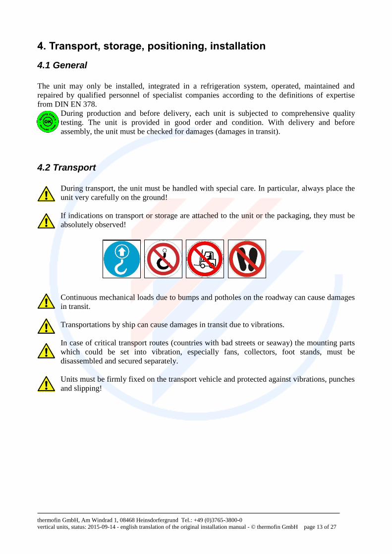
During transport, the unit must be handled with special care. In particular, always place the
unit very carefully on the ground!
If indications on transport or storage are attached to the unit or the packaging, they must be
absolutely observed!
Continuous mechanical loads due to bumps and potholes on the roadway can cause damages
in transit.
Transportations by ship can cause damages in transit due to vibrations.
In case of critical transport routes (countries with bad streets or seaway) the mounting parts
which could be set into vibration, especially fans, collectors, foot stands, must be
disassembled and secured separately.
Units must be firmly fixed on the transport vehicle and protected against vibrations, punches
and slipping!
thermofin GmbH, Am Windrad 1, 08468 Heinsdorfergrund Tel.: +49 (0)3765-3800-0
vertical units, status: 2015-09-14 - english translation of the original installation manual - © thermofin GmbH page 14 of 27
4.2.1 Packing
Decisive factors for packing are the route of transport, the size of the equipment and the regulations
applicable in the country of importation.
If not otherwise expressly agreed, the delivery is effected ex works in standard transport
packaging at the discretion of thermofin®. According to contractual agreement, design and
packaging are sufficient for the transport to the contractual agreed place of transfer of risk.
The purchaser is responsible for a possible further transport and the respective packaging.
In case of a packaging by external companies ordered by the purchaser or the customer,
thermofin® cannot give any warranty for the design of the packaging and possible resulting
transport damages. A safe design of the packaging should be agreed with thermofin®.
The pallets, crates and export boxes used for thermofin® units meet the requirements of the HPE
and VDM standards (HPE – German Federal Association for Wooden Packages, Pallets and Export
Packaging; VDM – Association of the German Furniture Industries). If required, they can be
tailored to the standards of ISPM 15.
thermofin® transport packages are made of environmental friendly materials and they are suitable
for recycling.
According to the German regulation on packaging, we are prepared to take back our packages if
they are returned to us, delivered free to our location in Heinsdorfergrund.
Usually, thermofin® units are provided completely assembled, with the exception of the vibration
dampers which are always delivered as loose parts (together with the unit). In the event that a unit is
delivered disassembled – due to transportation or other reasons – it must be assembled on site
according to the order-specific drawings enclosed.
Loading on road vehicles is performed in accordance with the VDI guideline 2700 "Securing of
loads on road vehicles".
In case of groupage traffic and reloading, the responsibility lies with the forwarder.
4.3 Storage
If the units must be stored, the following points must be observed:
Store the units on a proper, dry place protected against environmental influences! Protect the
fans against rain and condensation humidity (cold-warm)!
Store the units in an uprising, torsion-free and deflection-free manner!
Do not open the junctions; maintain the delivery pressure of the unit!
thermofin GmbH, Am Windrad 1, 08468 Heinsdorfergrund Tel.: +49 (0)3765-3800-0
vertical units, status: 2015-09-14 - english translation of the original installation manual - © thermofin GmbH page 15 of 27
4.4 Lifting and positioning
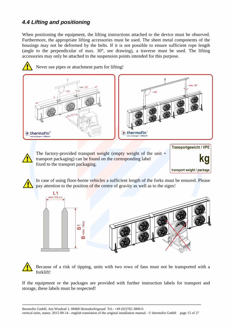
When positioning the equipment, the lifting instructions attached to the device must be observed.
Furthermore, the appropriate lifting accessories must be used. The sheet metal components of the
housings may not be deformed by the belts. If it is not possible to ensure sufficient rope length
(angle to the perpendicular of max. 30°, see drawing), a traverse must be used. The lifting
accessories may only be attached to the suspension points intended for this purpose.
Never use pipes or attachment parts for lifting!
The factory-provided transport weight (empty weight of the unit +
transport packaging) can be found on the corresponding label
fixed to the transport packaging.
In case of using floor-borne vehicles a sufficient length of the forks must be ensured. Please
pay attention to the position of the centre of gravity as well as to the signs!
Because of a risk of tipping, units with two rows of fans must not be transported with a
forklift!
If the equipment or the packages are provided with further instruction labels for transport and
storage, these labels must be respected!
thermofin GmbH, Am Windrad 1, 08468 Heinsdorfergrund Tel.: +49 (0)3765-3800-0
vertical units, status: 2015-09-14 - english translation of the original installation manual - © thermofin GmbH page 16 of 27
4.5 Installation
The suitability and the load bearing capacity of the foundations, brackets, machine frames etc.
– provided by the customer – are not the responsibility of the equipment manufacturer.
Within the calculation of the bearing load, additionally to the empty weight of the unit, also the
weight of the tube content as well as possible additional weights such as snow, humidity and dirt
must be taken into consideration.
Pay attention to possible wind loads! If necessary, the unit must be suitably supported on te
upper side, e.g. by anchoring.
It must be ensured that the building ground and supporting structure withstand the unit load
permanently and that deformations or soil settlements are prevented.
It has to be ensured that the machine rests evenly on all contact points in a torsion-free and
deflection-free manner. It must be fixed on the supporting structure by using appropriate fasteners.
For this purpose, the mounting holes provided on the feet of the units shall be used.
The optional vibration dampers with anti-noise properties – included in delivery –
are specifically designed for the respective unit. They are installed under the unit feet on site. The
vibration dampers are only suited for absorbing vertical compressive forces. Therefore, each kind of
shear or tractive force in transverse direction must be prevented. In the worst case, these forces may
destroy the foot.
The installation in accumulated water (recesses, glycol collection trays…) may lead to
rusting on the vibration dampers of the feet and may endanger the stability of the unit.
After installation and before commissioning all existing package parts and transport protection
devices must be removed.
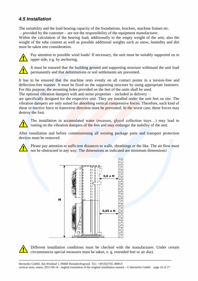
Please pay attention to sufficient distances to walls, sheathings or the like. The air flow must
not be obstructed in any way. The dimensions as indicated are minimum dimensions!
Different installation conditions must be checked with the manufacturer. Under certain
circumstances special measures must be taken, e. g. extended feet or air duct.
thermofin GmbH, Am Windrad 1, 08468 Heinsdorfergrund Tel.: +49 (0)3765-3800-0
vertical units, status: 2015-09-14 - english translation of the original installation manual - © thermofin GmbH page 17 of 27
4.6 Pipe connection
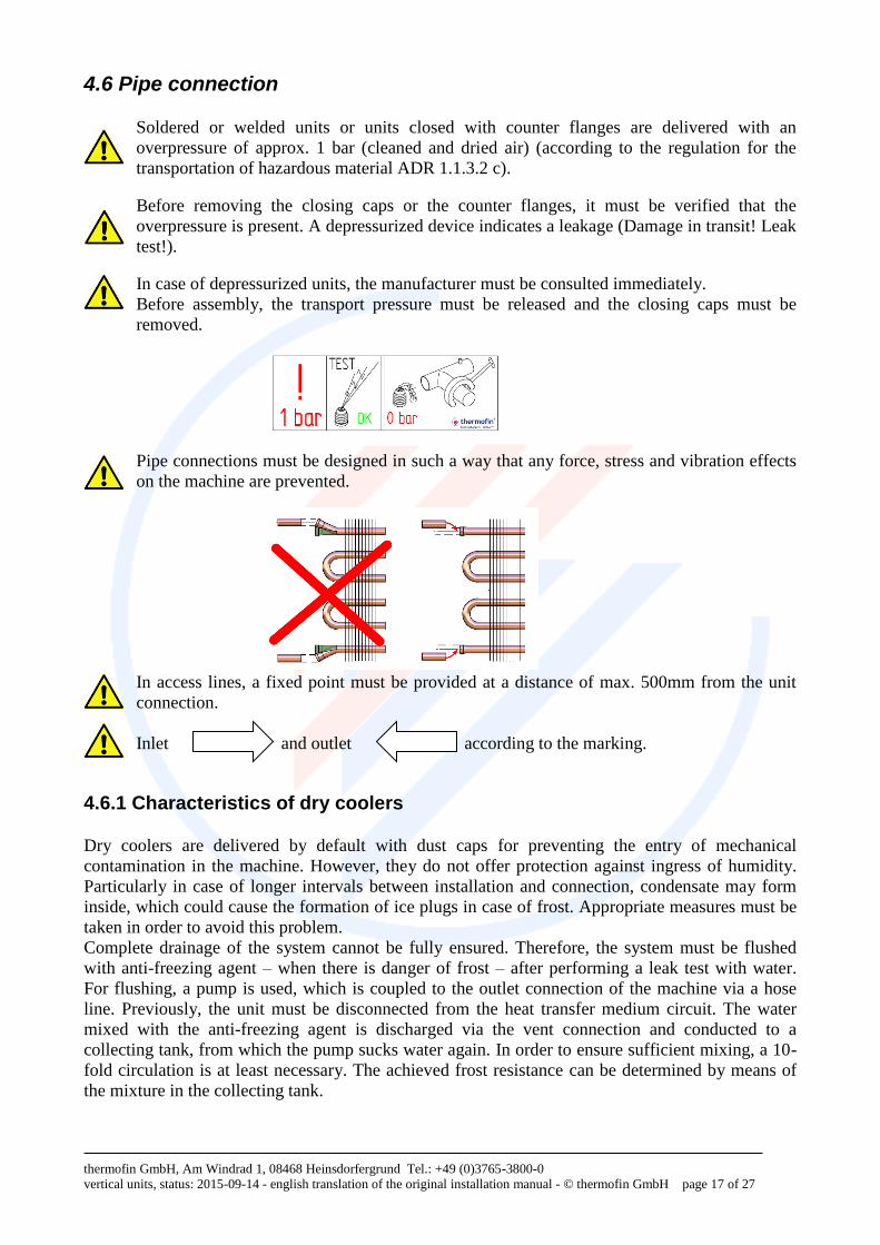
Soldered or welded units or units closed with counter flanges are delivered with an
overpressure of approx. 1 bar (cleaned and dried air) (according to the regulation for the
transportation of hazardous material ADR 1.1.3.2 c).
Before removing the closing caps or the counter flanges, it must be verified that the
overpressure is present. A depressurized device indicates a leakage (Damage in transit! Leak
test!).
In case of depressurized units, the manufacturer must be consulted immediately.
Before assembly, the transport pressure must be released and the closing caps must be
removed.
Pipe connections must be designed in such a way that any force, stress and vibration effects
on the machine are prevented.
In access lines, a fixed point must be provided at a distance of max. 500mm from the unit
connection.
Inlet and outlet according to the marking.
4.6.1 Characteristics of dry coolers
Dry coolers are delivered by default with dust caps for preventing the entry of mechanical
contamination in the machine. However, they do not offer protection against ingress of humidity.
Particularly in case of longer intervals between installation and connection, condensate may form
inside, which could cause the formation of ice plugs in case of frost. Appropriate measures must be
taken in order to avoid this problem.
Complete drainage of the system cannot be fully ensured. Therefore, the system must be flushed
with anti-freezing agent – when there is danger of frost – after performing a leak test with water.
For flushing, a pump is used, which is coupled to the outlet connection of the machine via a hose
line. Previously, the unit must be disconnected from the heat transfer medium circuit. The water
mixed with the anti-freezing agent is discharged via the vent connection and conducted to a
collecting tank, from which the pump sucks water again. In order to ensure sufficient mixing, a 10-
fold circulation is at least necessary. The achieved frost resistance can be determined by means of
the mixture in the collecting tank.
thermofin GmbH, Am Windrad 1, 08468 Heinsdorfergrund Tel.: +49 (0)3765-3800-0
vertical units, status: 2015-09-14 - english translation of the original installation manual - © thermofin GmbH page 18 of 27
5. Fans and electric system
5.1 Connection and installation
The electrical connection of the fans and/or the electrical accessories, if existent, must be
performed in accordance with the applicable national regulations and the provisions of the
local energy supply company!
The electrical installation may only be carried out by qualified personnel.
The local regulations must be observed.
A suitable all-pole separator, which is not included in thermofin®‘s scope of supply, must
be integrated in the installation.
In order to prevent an unintended start, the deactivation system must be possible to protect it
in deenergised (deactivated) condition!
Wiring may only be performed in accordance with the circuit and wiring diagrams
provided.
The existing strain-relief devices must always be used.
The direction of rotation of the fans must be observed!
The thermal motor protection is either already integrated in the electrical feed line of the
fans or shall be integrated in the electrical control system by the company installing the
system (see wiring diagram of the fans). It must be ensured that motors with released
thermal protector cannot be activated before the winding is cooled down. Otherwise, the
warranty claim expires!
Observe the information given on the type plate! The capacity and the power consumption
of the fans directly depends on the ambient temperature (air density) and can be, in case of
cold temperatures, above the information given on the type plate.
With the installation it must be observed that humidity can condensate in cold rooms and
that dripping water can be formed in the sockets! If the fans are provided with condensate
water holes, respectively the lower ones shall be opened! A non-compliance leads to the
expiration of warranty claims!
In circumstances, in order to prevent an entrance of condensation, fans in cold environment
should be hold on temperature during standstill using a standstill heater. Thermal motor
protection required!
In case of humidity entry due to spraying, sprinkling or jet water, a standstill heater is
necessary. A thermal motor protection is obligatory!
An icing of the impellers and fan nozzles must be prevented! Ice residues on impellers lead
to imbalances and damages to the fan! A noncompliance leads to the expiration of warranty
claims!
thermofin GmbH, Am Windrad 1, 08468 Heinsdorfergrund Tel.: +49 (0)3765-3800-0
vertical units, status: 2015-09-14 - english translation of the original installation manual - © thermofin GmbH page 19 of 27
For all works on fans and motors as well as cleaning works between the fans and the heat
exchanger coil (inspection cover), the power supply must be deactivated and protected
against restart!
After finishing repair and maintenance works, ensure that no objects remain in fan proximity
since they can cause errors and damages to the fan or heat exchanger after restart. After
disassembling the fans and their reinstallation, the free running must be checked.
In case of longer down times of the system, e.g. storage, the fans must be operated for
approx. 3 to 4 hours per month in order to evaporate condensations and to move the
bearings.
For the installation of the unit or subsequent installations assure compliance with the
degree of protection. In particular the sealing of the cable glands and terminal covers must
be checked for intactness and correct fitting.
For further information on the connection of fans, controllers, standstill heaters and thermal motor
protection systems, please refer to customer information FB.02.07 provided in the download area of
our website or which we can send to you upon request.
5.2 Fans with EC motors
In some circumstances, EC fans remain energised in deactivated condition on power-side
and are switched on control side.
Depending on the used fan type, the control can be effected via different BUS-systems, 0-
10V-signal or 4-20mA. Order-specific documents as well as the provided fan documentation
and/or wiring and connection plan, must be observed.
5.3 Fans with external rotor motors
All serial units delivered by thermofin®, are equipped with maintenance-free, energy-saving fans of
renowned manufacturers. However, fans should be checked regularly according to maintenance
plan (point 7) for function, bearing noises, free running and imbalances. Furthermore, terminal
covers must be checked for tight fitting and sealing. Since the bearings are ex-works maintenance
free and lubricated for lifetime, an individual check is not required. In case of longer down times
of the system, e.g. storage, the fans must be operated for approx. 3 to 4 hours per month in
order to evaporate condensation and to move the bearings.
5.4 Fans with standard motors or ATEX motors
Maintenance measures and maintenance intervals must be effected according to the information of
the motor manufacturer. If there is no information of the motor manufacturer, proceed according to
inspection and maintenance plan (chapter 7). Lower closed condensate holes should be opened
minimum twice per year. Depending on application, the bearings and/or the bearing lubricant have a
limited lifetime and must be checked and replaced according to maintenance plan (chapter 7). In
case of a bearing replacement, also the shaft seals (Stefa rings) must be replaced. Impellers must be
regularly checked for imbalance, tight fitting, soiling and corrosion.
thermofin GmbH, Am Windrad 1, 08468 Heinsdorfergrund Tel.: +49 (0)3765-3800-0
vertical units, status: 2015-09-14 - english translation of the original installation manual - © thermofin GmbH page 20 of 27
In case of longer down times of the system, e.g. storage, the fans must be operated for approx.
3 to 4 hours per month in order to evaporate condensation and to move the bearings.
All components that were removed, loosened or disassembled for cleaning or inspection
purposes must be properly reinstalled after work completion. They must also be checked for
correct functioning!
Further preventive measures are in the discretion of the system operator or the company installing
the system.
5.5 Electrical switching and control mechanisms
thermofin® offers different variant options with maintenance switch or motor protection switch,
phase angle control or frequency regulators as well as combinations thereof – on demand, fully pre-
wired. Here, a function test should be performed at regular intervals. The cables and components
must be subjected to a visual inspection; the terminals must be checked for tight fitting. In addition,
it must be checked whether the set parameters are still in line with the system configuration.
All components that were removed, loosened or disassembled for cleaning or inspection
purposes must be properly reinstalled after work completion. They must also be checked for
correct functioning!
5.5.1 Information on speed regulations
In case of regulating the fans with frequency converter, the use of an all-pole sinus filter
between converter and fans is mandatory! In case of non-observance the warranty expires!
In case of a phase angle regulation, electromagnetic motor noises (buzzing) are possible in
the lower speed range. In sensitive environments, a sound filter should be added.
For dimensioning of the phase angle regulation, a possible control-related current increase
should be taken into consideration. In case of doubt, the manufacturer should be contacted.
Pressure and temperature sensors must be properly installed and connected. Tightness and a
good heat transfer must be ensured. Shield signal cables and lay them separately from the
load cables!
thermofin GmbH, Am Windrad 1, 08468 Heinsdorfergrund Tel.: +49 (0)3765-3800-0
vertical units, status: 2015-09-14 - english translation of the original installation manual - © thermofin GmbH page 21 of 27
6. Commissioning, normal operation, maintenance, shutdown, disposal
6.1 Commissioning
Before starting operation, the system’s readiness for operation must be verified according to the
following points:
1. Has the unit been properly installed and fixed in accordance with the instructions of the
present manual?
2. Have all fluid-carrying lines been connected and checked for tightness? Are the shut-off
devices open?
3. Is the flow direction correct?
4. Are all cables properly installed and completely connected? Has cabling been done
according to the wiring diagrams provided?
5. Has the electrical protective installation been checked for proper functioning?
6. Have all bolted connections (e.g. fans, cable entries), fastenings, electrical connections etc.
been checked for tight fit?
7. Are all terminal boxes and cable entries firmly closed and tight?
8. Do the fans rotate freely and in the right direction? During start of operation the following measures shall be taken:
6.1.1 Return to service after a longer period of standstill
If the unit is intended to be put into operation again after being shut down and standing still for a
longer period of time, the following points must checked in addition to those mentioned under “6.1
Commissioning”:
1. Visual inspection of the heat exchanger coil, check for fouling and damages
2. Leak test of the heat exchanger coil
3. Visual inspection and functional test of the fans; check for free running, check the terminal
boxes for tightness, check for corrosion and noise (bearings)
4. Check all pipe connections (including pipe clips), electrical components, housings and
attachment parts for tight fit
6.2 Normal operation
In case of operating conditions which differ from those stated in the quotation, the manufacturer
must be consulted.
1. Check and, if necessary, adjust the direction of rotation of the fans.
2. Measure the current consumption of the fans and check for compliance with the type plate
data.
3. Adjust the electrical switching and control devices and check for correct functioning (see the
specific operating instructions of the respective control device).
4. Check the switch point settings of the safety equipment.
For running the unit, the entire plant including the electrical system must be operating.
The unit is integrated in the cooling circuit by opening the corresponding shut-off valves.
It is turned on by activating the electrical system.
After reaching the system-specific operating point the unit is ready for operation.
thermofin GmbH, Am Windrad 1, 08468 Heinsdorfergrund Tel.: +49 (0)3765-3800-0
vertical units, status: 2015-09-14 - english translation of the original installation manual - © thermofin GmbH page 22 of 27
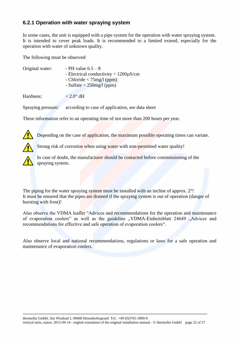
6.2.1 Operation with water spraying system
In some cases, the unit is equipped with a pipe system for the operation with water spraying system.
It is intended to cover peak loads. It is recommended to a limited extend, especially for the
operation with water of unknown quality.
The following must be observed:
Original water: - PH value 6.5 – 8
- Electrical conductivity < 1200µS/cm
- Chloride < 75mg/l (ppm)
- Sulfate < 250mg/l (ppm)
Hardness: < 2.0° dH
Spraying pressure: according to case of application, see data sheet
These information refer to an operating time of not more than 200 hours per year.
Depending on the case of application, the maximum possible operating times can variate.
Strong risk of corrosion when using water with non-permitted water quality!
In case of doubt, the manufacturer should be contacted before commissioning of the
spraying system.
The piping for the water spraying system must be installed with an incline of approx. 2°!
It must be ensured that the pipes are drained if the spraying system is out of operation (danger of
bursting with frost)!
Also observe the VDMA leaflet “Advices and recommendations for the operation and maintenance
of evaporation coolers” as well as the guideline „VDMA-Einheitsblatt 24649 „Advices and
recommendations for effective and safe operation of evaporation coolers“.
Also observe local and national recommendations, regulations or laws for a safe operation and
maintenance of evaporation coolers.
thermofin GmbH, Am Windrad 1, 08468 Heinsdorfergrund Tel.: +49 (0)3765-3800-0
vertical units, status: 2015-09-14 - english translation of the original installation manual - © thermofin GmbH page 23 of 27
6.3 Maintenance
The manufacturer recommends performing particular maintenance works at regular intervals.
The type and frequency of the measures strongly depend on the respective installation site of the
heat exchanger.
6.3.1 Cleaning of the fins
Depending on the installation site, mode of operation and the season, the heat exchanger fins are
subject to fouling (varying degree). As this directly affects the performance and thus the current
consumption of the machine, the cleanliness of the finned coil must always be ensured.
Dry cleaning: with a broom or a soft brush from the outside towards the fins or from the inside
towards the outside by using compressed air – opposite to the direction of the air flow of the fans.
Switch off the unit (regarding refrigeration and electricity)!
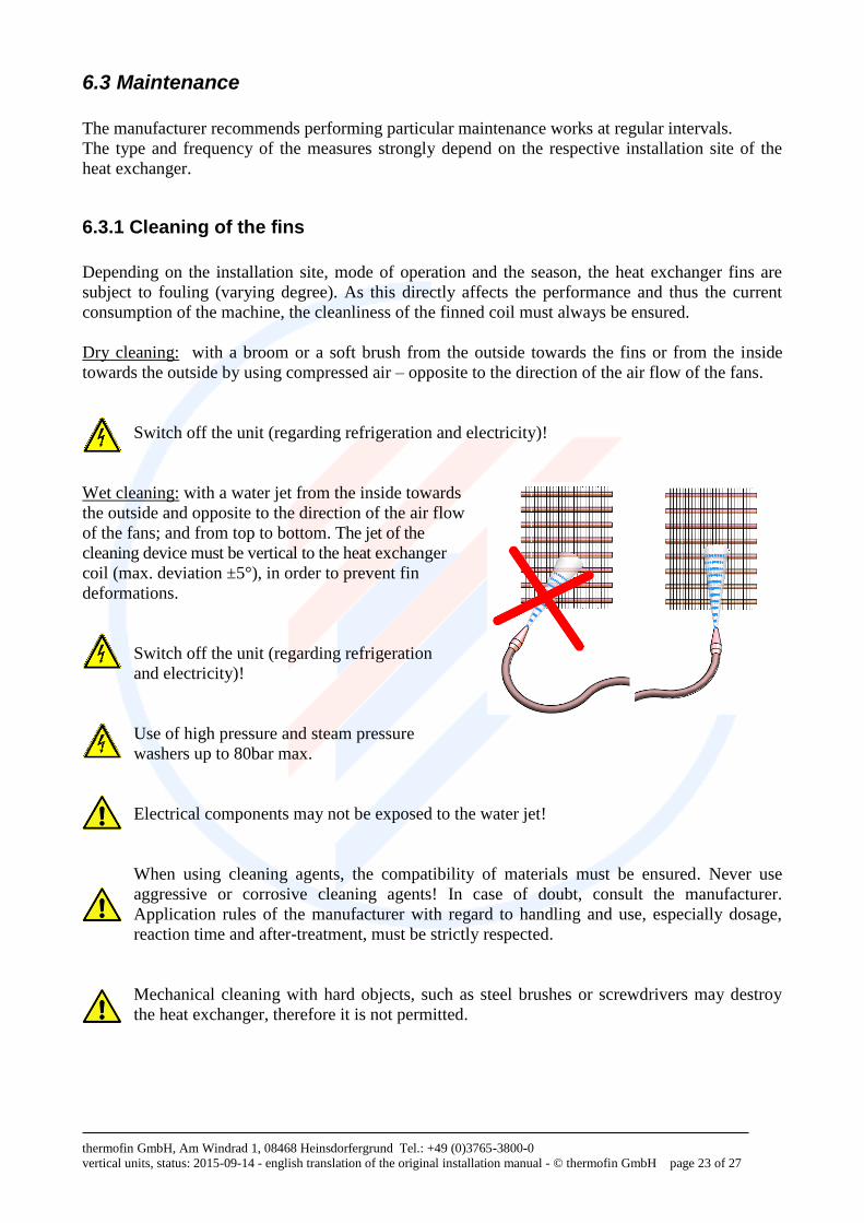
Wet cleaning: with a water jet from the inside towards
the outside and opposite to the direction of the air flow
of the fans; and from top to bottom. The jet of the
cleaning device must be vertical to the heat exchanger
coil (max. deviation ±5°), in order to prevent fin
deformations.
Switch off the unit (regarding refrigeration
and electricity)!
Use of high pressure and steam pressure
washers up to 80bar max.
Electrical components may not be exposed to the water jet!
When using cleaning agents, the compatibility of materials must be ensured. Never use
aggressive or corrosive cleaning agents! In case of doubt, consult the manufacturer.
Application rules of the manufacturer with regard to handling and use, especially dosage,
reaction time and after-treatment, must be strictly respected.
Mechanical cleaning with hard objects, such as steel brushes or screwdrivers may destroy
the heat exchanger, therefore it is not permitted.
thermofin GmbH, Am Windrad 1, 08468 Heinsdorfergrund Tel.: +49 (0)3765-3800-0
vertical units, status: 2015-09-14 - english translation of the original installation manual - © thermofin GmbH page 24 of 27
6.3.2 Cleaning of the casings
thermofin® heat exchanger casings have smooth surfaces which are equipped with a hygienic,
corrosion-resistant powder coating which makes the cleaning of the devices very easy. The devices
should be cleaned with water or a mild soap leach.
In order to comply with special hygienic requirements, devices with a casing made of stainless steel
must be used where necessary.
When using cleaning agents, please observe the compatibility of materials. Never use
aggressive or corrosive cleaning agents. If necessary, contact the manufacturer or the
supplier of the cleaning agent. Application rules of the manufacturer with regard to handling
and use, especially dosage, reaction time and after-treatment, must be strictly respected.
Under no circumstances use sharp-edged tools or scrapers!
Potentially existing dust filters are removable and can be cleaned by means of a vacuum cleaner or
under running water.
6.4 Spare parts
After-sales services shall be performed by the responsible specialist company. Spare parts are stated
in the spare parts list enclosed in the annex or in the specified drawing. They can also be requested
from the manufacturer by indicating the device name and the project number on the type plate.
Only use original spare parts for the replacement of equipment components.
6.5 Shutdown
The units are part of a cooling system. Unit shutdown and return to service must meet the system-
dependent requirements as well as the requirements of the operating manual of the equipment
manufacturer and of the applicable standards and accident prevention regulations (see also chapter
”Applied standards and directives“). The shutdown is effected by closing the fluid-bearing tubes
and by switching off the electrical system.
The following applies for all units: Exceeding the maximum pressure must be prevented!
In case of longer standstill periods of the system, the fans should be operated for approx. 3
to 4 hours per month.
6.6 Disposal
Empty the system properly in a technically correct manner; properly dispose of the working
fluid. No emissions in the environment!
Oil residuals must not reach the ground and must be disposed of with the special waste.
Bring the emptied unit to recycling.
thermofin GmbH, Am Windrad 1, 08468 Heinsdorfergrund Tel.: +49 (0)3765-3800-0
vertical units, status: 2015-09-14 - english translation of the original installation manual - © thermofin GmbH page 25 of 27
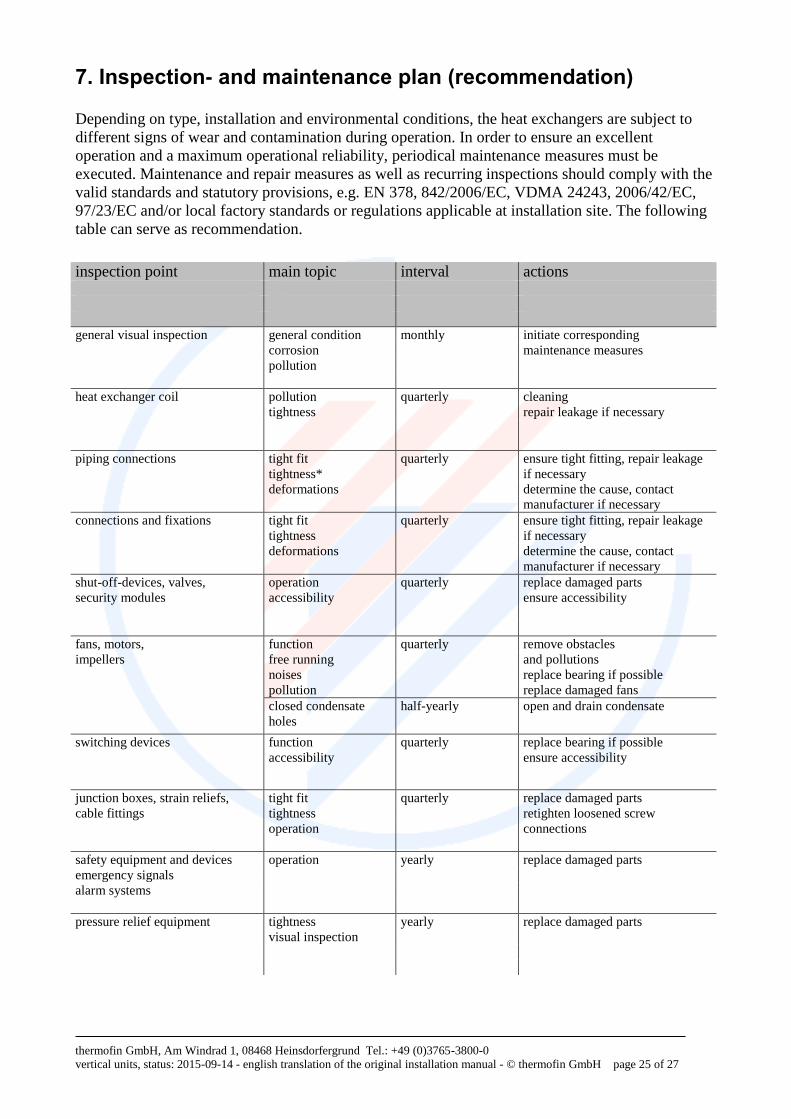
7. Inspection- and maintenance plan (recommendation)
Depending on type, installation and environmental conditions, the heat exchangers are subject to
different signs of wear and contamination during operation. In order to ensure an excellent
operation and a maximum operational reliability, periodical maintenance measures must be
executed. Maintenance and repair measures as well as recurring inspections should comply with the
valid standards and statutory provisions, e.g. EN 378, 842/2006/EC, VDMA 24243, 2006/42/EC,
97/23/EC and/or local factory standards or regulations applicable at installation site. The following
table can serve as recommendation.
inspection point main topic interval actions
general visual inspection general condition monthly initiate corresponding
corrosion maintenance measures
pollution
heat exchanger coil pollution quarterly cleaning
tightness repair leakage if necessary
piping connections tight fit quarterly ensure tight fitting, repair leakage
tightness* if necessary
deformations determine the cause, contact
manufacturer if necessary
connections and fixations tight fit quarterly ensure tight fitting, repair leakage
tightness if necessary
deformations determine the cause, contact
manufacturer if necessary
shut-off-devices, valves, operation quarterly replace damaged parts
security modules accessibility ensure accessibility
fans, motors, function quarterly remove obstacles impellers free running and pollutions noises replace bearing if possible
pollution replace damaged fans
closed condensate
holes
half-yearly open and drain condensate
switching devices function
accessibility
quarterly replace bearing if possible
ensure accessibility
junction boxes, strain reliefs, tight fit quarterly replace damaged parts
cable fittings tightness retighten loosened screw
operation connections
safety equipment and devices operation yearly replace damaged parts
emergency signals
alarm systems
pressure relief equipment tightness yearly replace damaged parts
visual inspection
thermofin GmbH, Am Windrad 1, 08468 Heinsdorfergrund Tel.: +49 (0)3765-3800-0
vertical units, status: 2015-09-14 - english translation of the original installation manual - © thermofin GmbH page 26 of 27
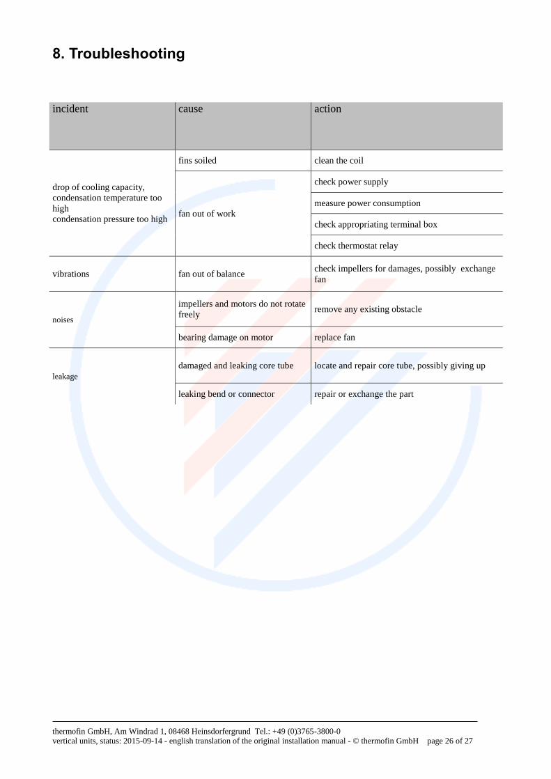
8. Troubleshooting
incident cause action
drop of cooling capacity,
condensation temperature too
high
condensation pressure too high
fins soiled clean the coil
fan out of work
check power supply
measure power consumption
check appropriating terminal box
check thermostat relay
vibrations fan out of balance check impellers for damages, possibly exchange
fan
noises
impellers and motors do not rotate
freely remove any existing obstacle
bearing damage on motor replace fan
leakage
damaged and leaking core tube locate and repair core tube, possibly giving up
leaking bend or connector repair or exchange the part
thermofin GmbH, Am Windrad 1, 08468 Heinsdorfergrund Tel.: +49 (0)3765-3800-0
vertical units, status: 2015-09-14 - english translation of the original installation manual - © thermofin GmbH page 27 of 27
Contact
Address: thermofin GmbH
Am Windrad 1
08468 Heinsdorfergrund
Germany
Phone: +49 3765 3800-0
Fax: +49 3765 3800-8038
E-mail: [email protected]
Internet: www.thermofin.de