Embed Size (px)
Citation preview
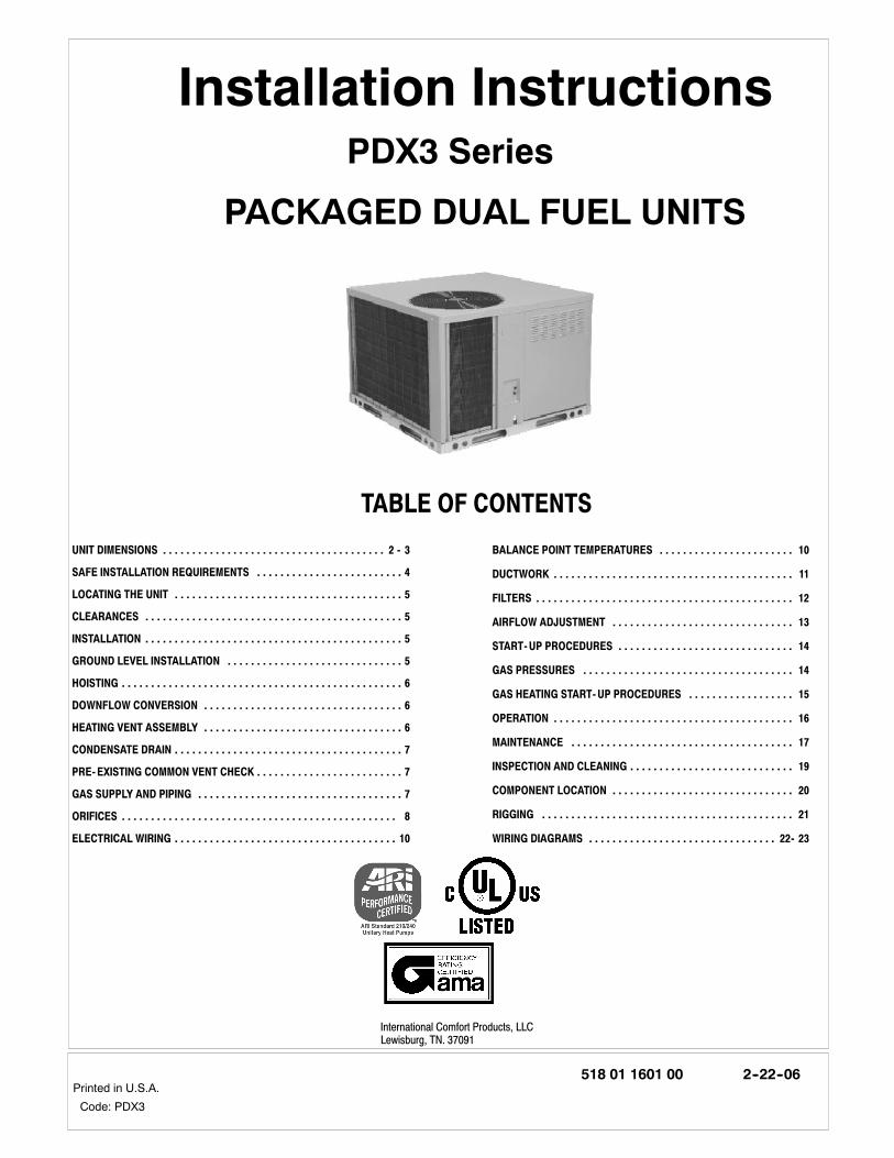
Printed in U.S.A.518 01 1601 00 2--22--06
PACKAGED DUAL FUEL UNITS
Installation InstructionsPDX3 Series
Code: PDX3
International Comfort Products, LLCLewisburg, TN. 37091
TABLE OF CONTENTS
UNIT DIMENSIONS 2 - 3. . . . . . . . . . . . . . . . . . . . . . . . . . . . . . . . . . . . . .
SAFE INSTALLATION REQUIREMENTS 4. . . . . . . . . . . . . . . . . . . . . . . . .
LOCATING THE UNIT 5. . . . . . . . . . . . . . . . . . . . . . . . . . . . . . . . . . . . . . .
CLEARANCES 5. . . . . . . . . . . . . . . . . . . . . . . . . . . . . . . . . . . . . . . . . . . .
INSTALLATION 5. . . . . . . . . . . . . . . . . . . . . . . . . . . . . . . . . . . . . . . . . . . .
GROUND LEVEL INSTALLATION 5. . . . . . . . . . . . . . . . . . . . . . . . . . . . . .
HOISTING 6. . . . . . . . . . . . . . . . . . . . . . . . . . . . . . . . . . . . . . . . . . . . . . . .
DOWNFLOW CONVERSION 6. . . . . . . . . . . . . . . . . . . . . . . . . . . . . . . . . .
HEATING VENT ASSEMBLY 6. . . . . . . . . . . . . . . . . . . . . . . . . . . . . . . . . .
CONDENSATE DRAIN 7. . . . . . . . . . . . . . . . . . . . . . . . . . . . . . . . . . . . . . .
PRE-EXISTING COMMON VENT CHECK 7. . . . . . . . . . . . . . . . . . . . . . . . .
GAS SUPPLY AND PIPING 7. . . . . . . . . . . . . . . . . . . . . . . . . . . . . . . . . . .
ORIFICES 8. . . . . . . . . . . . . . . . . . . . . . . . . . . . . . . . . . . . . . . . . . . . . . .
ELECTRICAL WIRING 10. . . . . . . . . . . . . . . . . . . . . . . . . . . . . . . . . . . . . .
BALANCE POINT TEMPERATURES 10. . . . . . . . . . . . . . . . . . . . . . .
DUCTWORK 11. . . . . . . . . . . . . . . . . . . . . . . . . . . . . . . . . . . . . . . . .
FILTERS 12. . . . . . . . . . . . . . . . . . . . . . . . . . . . . . . . . . . . . . . . . . . .
AIRFLOW ADJUSTMENT 13. . . . . . . . . . . . . . . . . . . . . . . . . . . . . . .
START-UP PROCEDURES 14. . . . . . . . . . . . . . . . . . . . . . . . . . . . . .
GAS PRESSURES 14. . . . . . . . . . . . . . . . . . . . . . . . . . . . . . . . . . . .
GAS HEATING START-UP PROCEDURES 15. . . . . . . . . . . . . . . . . .
OPERATION 16. . . . . . . . . . . . . . . . . . . . . . . . . . . . . . . . . . . . . . . . .
MAINTENANCE 17. . . . . . . . . . . . . . . . . . . . . . . . . . . . . . . . . . . . . .
INSPECTION AND CLEANING 19. . . . . . . . . . . . . . . . . . . . . . . . . . . .
COMPONENT LOCATION 20. . . . . . . . . . . . . . . . . . . . . . . . . . . . . . .
RIGGING 21. . . . . . . . . . . . . . . . . . . . . . . . . . . . . . . . . . . . . . . . . . .
WIRING DIAGRAMS 22- 23. . . . . . . . . . . . . . . . . . . . . . . . . . . . . . . .
2
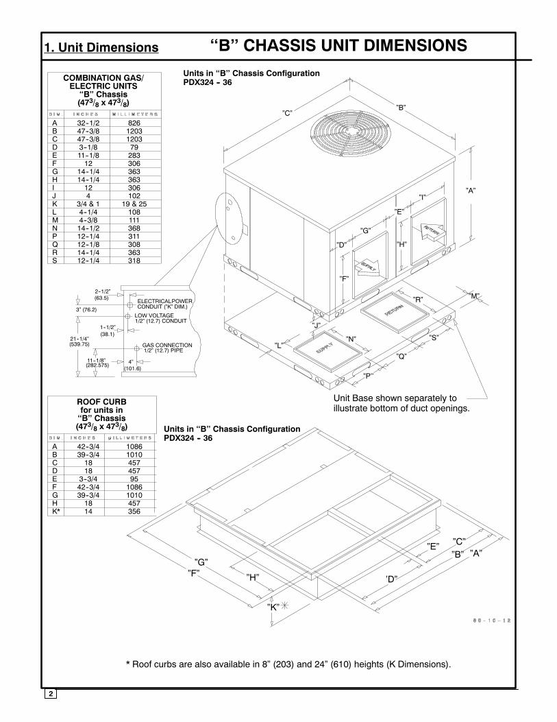
A 32--1/2 826B 47--3/8 1203C 47--3/8 1203D 3--1/8 79E 11--1/8 283F 12 306G 14--1/4 363H 14--1/4 363I 12 306J 4 102K 3/4 & 1 19 & 25L 4--1/4 108M 4--3/8 111N 14--1/2 368P 12--1/4 311Q 12--1/8 308R 14--1/4 363S 12--1/4 318
COMBINATION GAS/ELECTRIC UNITS
‘‘B’’ Chassis(473/8 x 473/8)
ROOF CURBfor units in‘‘B’’ Chassis(473/8 x 473/8)
Units in ‘‘B’’ Chassis ConfigurationPDX324 -- 36
Units in ‘‘B’’ Chassis ConfigurationPDX324 -- 36
ELECTRICALPOWER
LOW VOLTAGE1/2” (12.7) CONDUIT
GAS CONNECTION1/2” (12.7) PIPE
CONDUIT (”K” DIM.)
2--1/2”(63.5)
3” (76.2)
1--1/2”(38.1)
21--1/4”(539.75)
11--1/8”(282.575) 4”
(101.6)
”G””F” ”H”
”K”
’D”
”E” ”C””B” ”A”
”C””B”
”A”
”D”
”G”
”E”
”I”
”H”
”F”
”L”
”J”
”N”
”R” ”M”
”S”
”Q”
”P’’
A 42--3/4 1086B 39--3/4 1010C 18 457D 18 457E 3--3/4 95F 42--3/4 1086G 39--3/4 1010H 18 457K* 14 356
‘‘B’’ CHASSIS UNIT DIMENSIONS1. Unit Dimensions
Unit Base shown separately toillustrate bottom of duct openings.
* Roof curbs are also available in 8” (203) and 24” (610) heights (K Dimensions).
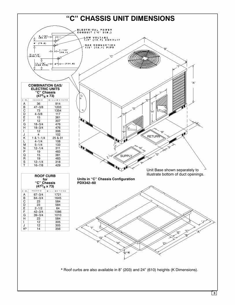
COMBINATION GAS/ELECTRIC UNITS
‘‘C’’ Chassis(473/8 x 73)
ROOF CURBfor
‘‘C’’ Chassis(473/8 x 73)
Units in ‘‘C’’ Chassis ConfigurationPDX342--60
”C”
”B”
”A”
”I”
”E”
”G”
”D”
”F”
”J”
”H”
”L”
”N”
”R”
”S”
”Q”
”P”
”M”
SUPPLY
RETURN
”G””F” ”H”
”K”
’D”
”E” ”C””B”
”A”
”J”
”I”
”T”
A 36 914B 47--3/8 1203C 73 1354D 4--5/8 117E 15 361F 12 307G 18--3/4 476H 18--3/4 476I 12 306J 4 102K 1 & 1--1/4 25 & 31L 4--1/4 108M 5--1/4 133N 12--1/4 311P 19 483Q 15 381R 19 483S 12--1/4 318T 16--7/8 429
A 67--3/4 1721B 64--3/4 1645C 23 584D 23 584E 2--1/2 64F 42--3/4 1086G 39--3/4 1010H 23 584I 12 305J 12 305K* 14 356
‘‘C’’ CHASSIS UNIT DIMENSIONS
Unit Base shown separately toillustrate bottom of duct openings.
* Roof curbs are also available in 8” (203) and 24” (610) heights (K Dimensions).
3
4
2. SAFE INSTALLATION REQUIREMENTS
Installationandservicingof air--conditioningequipment canbe hazardous due to system pressure and electricalcomponents. Only trained and qualified personnel shouldinstall, repair, or service air--conditioning equipment.Untrained personnel can perform basic maintenancefunctions of cleaning coils and filters. All other operationsshould be performed by trained service personnel. Whenworking on air--conditioning equipment, observeprecautions in the literature, tags, and labels attached to theunit, and other safety precautions that may apply.Follow all safety codes. Wear safety glasses and workgloves. Use quenching cloth for unbrazing operations.Have fire extinguisher available for all brazing operations.
FIRE, EXPLOSION, ELECTRICAL SHOCK, ANDCARBON MONOXIDE POISON HAZARD
Improper installation, adjustment, alteration, service,maintenance, or use can cause carbon monoxidepoisoning, fire, or an explosion which could result inpersonal injury or unit damage. Consult a qualifiedinstaller, service agency, or gas supplier for informationor assistance. The qualified installer or agencymust useonly factory--authorized kits or accessories whenmodifying this product.
!
FIRE, EXPLOSION, ELECTRICAL SHOCK, ANDCARBON MONOXIDE POISON HAZARD
Failure to follow this warning could result in personalinjury, death and/or property damage.
Before performing service or maintenance operationsonunit, turnoff gassupply tounit.Then turnoff unitmainpower switch and install lockout tag.
!
Recognize safety information. This is the safety--alertsymbol . When you see this symbol in instructions ormanuals, be alert to the potential for personal injury.
Understand the signal words DANGER, WARNING,CAUTION, and NOTE. These words are used with thesafety--alert symbol. DANGER identifies the most serioushazards which will result in serious injury or death.WARNING signifies a hazard which could result in seriousinjury or death. CAUTION is used to identify unsafepractices which may result in minor personal injury orproduct and property damage. NOTE is used to highlightsuggestions which will result in enhanced installation,reliability, or operation.
These instructions cover minimum requirements andconform to existing national standards and safety codes. Insome instances, these instructions exceed certain localcodes and ordinances, especially those that may not havekept up with changing residential construction practices.We require these instructions as a minimum for a safeinstallation.
FIRE, EXPLOSION, ELECTRICAL SHOCK, AND CARBONMONOXIDE POISON HAZARD
!
Failure to carefully read and follow all instructions in thismanual could result in furnace malfunction, propertydamage, personal injury and/or death.Installation or repairs made by unqualified persons canresult in hazards to you and others. Installation MUSTconform with local building codes or, in the absence oflocal codes, with the National Fuel Gas Code NFPA54--2005/ANSI Z223.1--2005 and the National ElectricalCode NFPA70--2005 or in Canada the National StandardCAN/CGA B149--1 and CSA C.22.1 -- Canadian ElectricalCode Part 1.The information contained in this manual is intended foruse by a qualified service technician familiar with safetyprocedures and equipped with the proper tools and testinstruments.
SAFETY CONSIDERATIONS•Use only with type of gas approved for this unit. Refer tounit rating plate.
• Install this unit only in a location and position as specifiedin section 3 of this manual.
•Never test for gas leaks with an open flame. Use a com-mercially available soap solution made specifically for thedetection of leaks to check all connections.
•Always install unit to operate within the unit’s intendedtemperature--rise range with a duct system, which has anexternal static pressure within the allowable range, asspecified in section 9. Refer to unit rating plate for the al-lowable external static pressures.
•All connecting ductwork to the unit (supply and return)must be sealed to the unit casing.
•Do NOT use this furnace as a construction heater.•Check to see that filters are installed correctly and are theproper type an size.NOTE: It is the personal responsibility and obligation of thecustomer to contact a qualified installer to ensure that theinstallation is adequate and conforms to governing codesand ordinances.
UNIT RELIABILITY HAZARDCAUTION!
Failure to follow this caution may reduce unit reliability.It is recommended that a qualified service techniciancheck the heat exchanger integrity every two (2) years,after the first four (4) years of operation.
INTRODUCTIONThe PDX3 unit is a fully self--contained, combinationCategory I gasheating / electric heat pumpunit designed foroutdoor installation (See pages 2 and 3 for unitdimensions). All unit sizes have return and dischargeopenings for both horizontal and downflow configurations,and are factory--shipped with all downflow duct openingscovered.Units may be installed either on a rooftop, cement slab, ordirectly on the ground if local codes permit.Modelswith a ‘‘1” in the twelfth position of themodel numberare dedicated Low NOx units designed for Californiainstallations. The emissions of thesemodels do not exceed40 nanograms of nitrogen oxide emissions per joule of heatoutput as shipped from the factory, and must be installed inCalifornia Air Quality Management Districts or any otherregions in North America where a Low NOx rule exists.
!
5
3. LOCATING THE UNIT
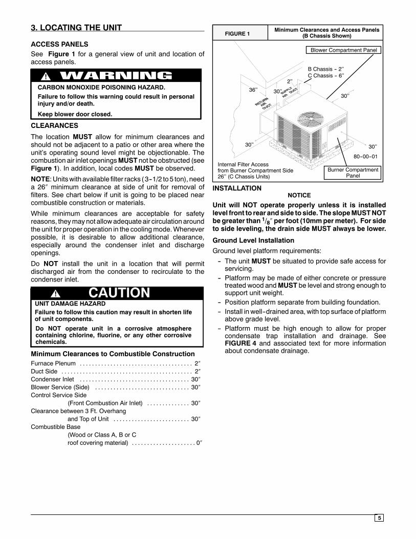
ACCESS PANELSSee Figure 1 for a general view of unit and location ofaccess panels.
CARBON MONOXIDE POISONING HAZARD.
!
Failure to follow this warning could result in personalinjury and/or death.
Keep blower door closed.
CLEARANCES
The location MUST allow for minimum clearances andshould not be adjacent to a patio or other area where theunit’s operating sound level might be objectionable. Thecombustion air inlet openingsMUST not be obstructed (seeFigure 1). In addition, local codes MUST be observed.
NOTE:Unitswith available filter racks ( 3--1/2 to5 ton), needa 26″ minimum clearance at side of unit for removal offilters. See chart below if unit is going to be placed nearcombustible construction or materials.
While minimum clearances are acceptable for safetyreasons, theymaynot allowadequateair circulationaroundthe unit for proper operation in the coolingmode.Wheneverpossible, it is desirable to allow additional clearance,especially around the condenser inlet and dischargeopenings.
Do NOT install the unit in a location that will permitdischarged air from the condenser to recirculate to thecondenser inlet.
Do NOT operate unit in a corrosive atmospherecontaining chlorine, fluorine, or any other corrosivechemicals.
CAUTION!UNIT DAMAGE HAZARDFailure to follow this caution may result in shorten lifeof unit components.
Minimum Clearances to Combustible ConstructionFurnace Plenum 2″. . . . . . . . . . . . . . . . . . . . . . . . . . . . . . . . . . . . .Duct Side 2″. . . . . . . . . . . . . . . . . . . . . . . . . . . . . . . . . . . . . . . . . . .Condenser Inlet 30″. . . . . . . . . . . . . . . . . . . . . . . . . . . . . . . . . . . .Blower Service (Side) 30″. . . . . . . . . . . . . . . . . . . . . . . . . . . . . . .Control Service Side
(Front Combustion Air Inlet) 30″. . . . . . . . . . . . . .Clearance between 3 Ft. Overhang
and Top of Unit 30″. . . . . . . . . . . . . . . . . . . . . . . . .Combustible Base
(Wood or Class A, B or Croof covering material) 0″. . . . . . . . . . . . . . . . . . . . .
FIGURE 1Minimum Clearances and Access Panels
(B Chassis Shown)
Burner CompartmentPanel
Blower Compartment Panel
80--00--01Internal Filter Accessfrom Burner Compartment Side26’’ (C Chassis Units)
30’’30’’
C Chassis -- 6’’
30’’ 30’’
36’’
2’’
B Chassis -- 2’’
INSTALLATIONNOTICE
Unit will NOT operate properly unless it is installedlevel front to rear andside toside. TheslopeMUSTNOTbe greater than 1/8″ per foot (10mmpermeter). For sideto side leveling, the drain side MUST always be lower.
Ground Level Installation
Ground level platform requirements:
-- The unit MUST be situated to provide safe access forservicing.
-- Platform may be made of either concrete or pressuretreated wood andMUST be level and strong enough tosupport unit weight.
-- Position platform separate from building foundation.-- Install in well--drained area, with top surface of platformabove grade level.
-- Platform must be high enough to allow for propercondensate trap installation and drainage. SeeFIGURE 4 and associated text for more informationabout condensate drainage.
6
Rooftop Installation
Rooftop platform requirements:
-- The unit MUST be situated to provide safe access forservicing.
-- The existing roof structure MUST be adequate tosupport the weight of the unit or the roof MUST bereinforced.Check the weight of the unit in relation to the roofstructure and local building codes or ordinances andreinforce roof structure if necessary. See the last pageof this manual for unit weights.
-- Support for the unitMUST be level and strong enoughto carry unit weight. The support may consist of aplatformor a combination of platformand roof beamsorcurb.
-- See Hoisting section for hoisting instructions.
HOISTING
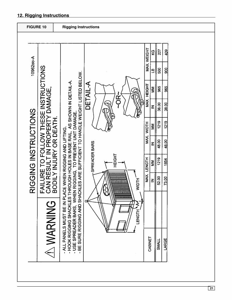
NOTE:All access panelsMUST be secured in place beforehoisting.
The unit should be hoisted with two lifting slings. Attach theslings to rigging shackles that have been hooked throughholes in the base rail.
Two spreader bars MUST be placed on top of the unit toprotect the unit from damage from the pressure exerted bythe slings. Make sure that all equipment is adequate tohandle theweight of the unit and that the slingswill not allowthe unit to shift.
Refer to FIGURE 10 on the back cover of this manual forillustrated rigging instructions and weight chart.
DOWNFLOW CONVERSION
NOTE: In downflow applications with roof curbs or jackstands, the center rail under the unit must be removed. Thecenter rail is attached to the base rail with screws.
These units are adaptable to downflow use. To convert todownflow use, follow these steps:
1. Remove the blockoff plates found in the return aircompartment and the supply air compartment.
NOTE: Blockoff plate in the supply air compartment onlycontains one screw. If reinstalling plate, back part of plateMUST fit into mating dimples on flange. To reinstall, slantplate into dimples, then put plate into position and fastenwith screw.
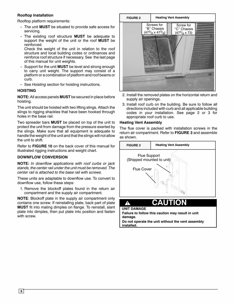
FIGURE 2 Heating Vent Assembly
Screws for‘‘B’’ Chassis(473/8 x 473/8)
Screw for‘‘C’’ Chassis(473/8 x 73)
2. Install the removed plates on the horizontal return andsupply air openings.
3. Install roof curb on the building. Be sure to follow alldirections includedwith curb and all applicable buildingcodes in your installation. See page 2 or 3 forappropriate roof curb to use.
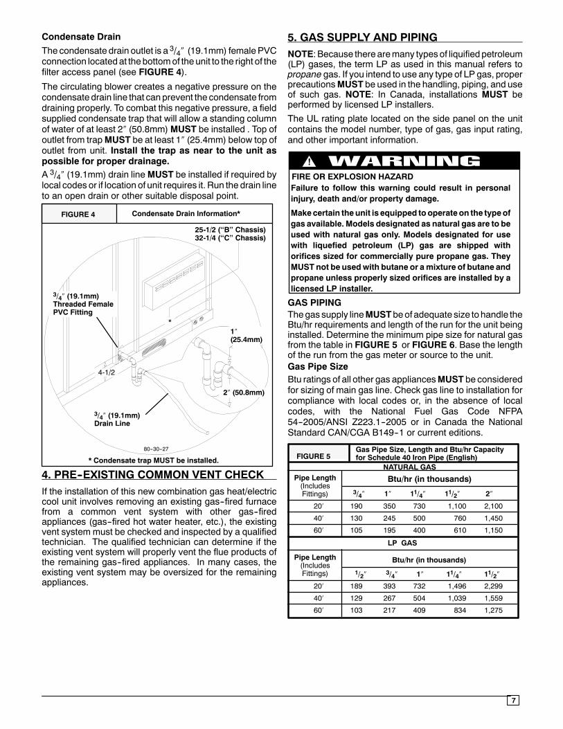
Heating Vent Assembly
The flue cover is packed with installation screws in thereturn air compartment. Refer to FIGURE 3 and assembleas shown.
FIGURE 3 Heating Vent Assembly
Flue Support(Shipped mounted to unit)
Flue Cover
UNIT DAMAGECAUTION!
Do not operate the unit without the vent assemblyinstalled.
Failure to follow this caution may result in unitdamage.
7
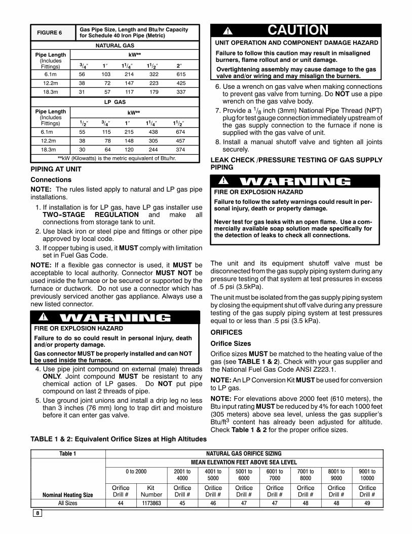
Condensate Drain
The condensate drain outlet is a 3/4″ (19.1mm) femalePVCconnection locatedat thebottomof theunit to the right of thefilter access panel (see FIGURE 4).
The circulating blower creates a negative pressure on thecondensate drain line that canprevent the condensate fromdraining properly. To combat this negative pressure, a fieldsupplied condensate trap that will allow a standing columnof water of at least 2″ (50.8mm)MUST be installed . Top ofoutlet from trapMUST be at least 1″ (25.4mm) below top ofoutlet from unit. Install the trap as near to the unit aspossible for proper drainage.A 3/4″ (19.1mm) drain lineMUST be installed if required bylocal codes or if location of unit requires it. Run the drain lineto an open drain or other suitable disposal point.
FIGURE 4 Condensate Drain Information*
* Condensate trap MUST be installed.
3/4″ (19.1mm)Drain Line
80--30--27
1″(25.4mm)
2″ (50.8mm)
3/4″ (19.1mm)Threaded FemalePVC Fitting
4-1/2
25-1/2 (‘‘B’’ Chassis)32-1/4 (‘‘C’’ Chassis)
*
4. PRE--EXISTING COMMON VENT CHECKIf the installation of this new combination gas heat/electriccool unit involves removing an existing gas--fired furnacefrom a common vent system with other gas--firedappliances (gas--fired hot water heater, etc.), the existingvent system must be checked and inspected by a qualifiedtechnician. The qualified technician can determine if theexisting vent system will properly vent the flue products ofthe remaining gas--fired appliances. In many cases, theexisting vent system may be oversized for the remainingappliances.
5. GAS SUPPLY AND PIPINGNOTE: Because therearemany typesof liquified petroleum(LP) gases, the term LP as used in this manual refers topropane gas. If you intend to use any type of LP gas, properprecautionsMUST be used in the handling, piping, and useof such gas. NOTE: In Canada, installations MUST beperformed by licensed LP installers.
The UL rating plate located on the side panel on the unitcontains the model number, type of gas, gas input rating,and other important information.
FIRE OR EXPLOSION HAZARDFailure to follow this warning could result in personalinjury, death and/or property damage.
Makecertain theunit is equipped tooperateon the typeofgas available. Models designated as natural gas are to beused with natural gas only. Models designated for usewith liquefied petroleum (LP) gas are shipped withorifices sized for commercially pure propane gas. TheyMUST not be usedwith butane or amixture of butane andpropane unless properly sized orifices are installed by alicensed LP installer.
!
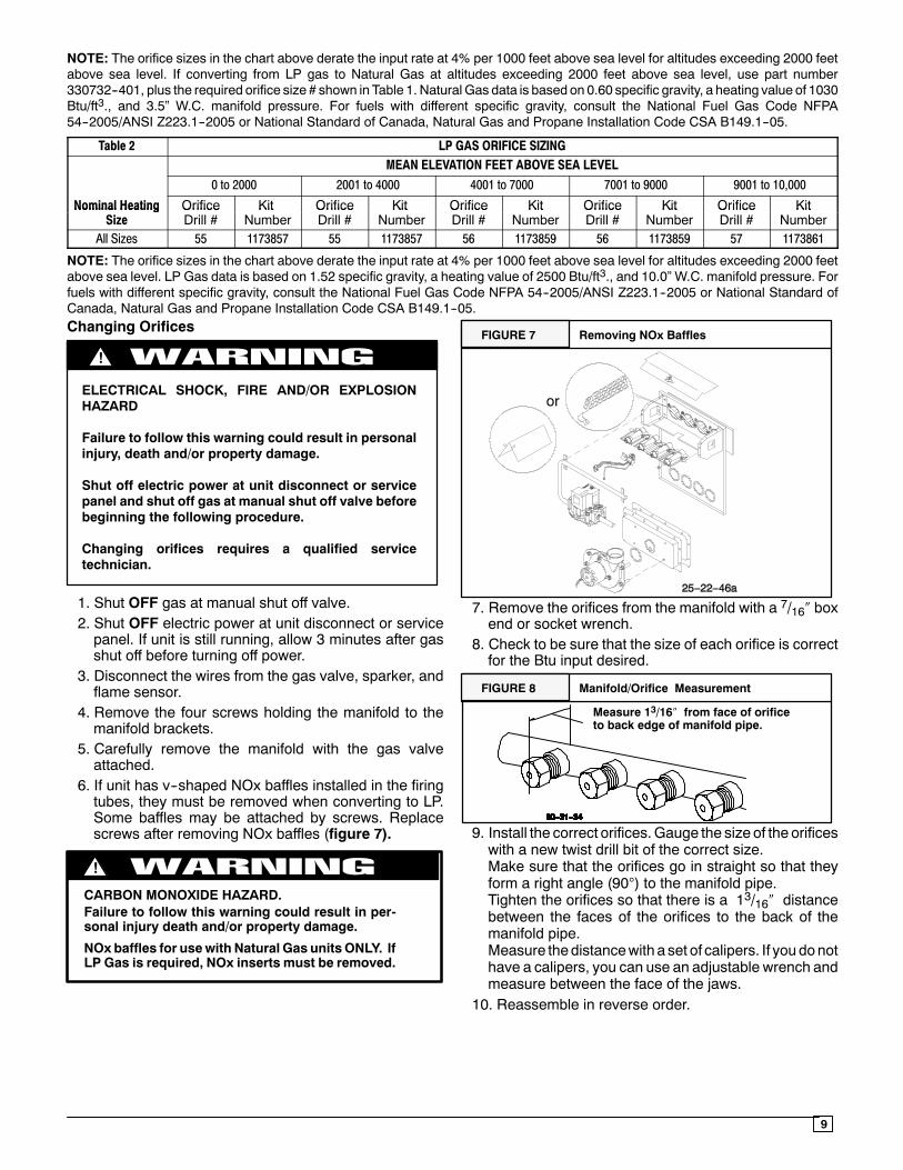
GAS PIPINGThegas supply lineMUSTbeof adequate size to handle theBtu/hr requirements and length of the run for the unit beinginstalled. Determine the minimum pipe size for natural gasfrom the table in FIGURE 5 or FIGURE 6. Base the lengthof the run from the gas meter or source to the unit.Gas Pipe SizeBtu ratings of all other gas appliancesMUST be consideredfor sizing of main gas line. Check gas line to installation forcompliance with local codes or, in the absence of localcodes, with the National Fuel Gas Code NFPA54--2005/ANSI Z223.1--2005 or in Canada the NationalStandard CAN/CGA B149--1 or current editions.
Gas Pipe Size, Length and Btu/hr Capacityfor Schedule 40 Iron Pipe (English)
20′ 190 350 730 1,100 2,100
40′ 130 245 500 760 1,450
60′ 105 195 400 610 1,150
FIGURE 5
Btu/hr (in thousands)
LP GAS
NATURAL GASPipe Length(IncludesFittings) 3/4″ 1″ 11/4″ 11/2″ 2″
20′ 189 393 732 1,496 2,299
40′ 129 267 504 1,039 1,559
60′ 103 217 409 834 1,275
Btu/hr (in thousands)Pipe Length(IncludesFittings) 1/2″ 3/4″ 1″ 11/4″ 11/2″
8
Pipe Length(IncludesFittings)
6.1m 56 103 214 322 615
12.2m 38 72 147 223 425
18.3m 31 57 117 179 337
FIGURE 6
kW**
LP GAS
NATURAL GAS
Pipe Length(IncludesFittings) 3/4″ 1″ 11/4″ 11/2″ 2″
6.1m 55 115 215 438 674
12.2m 38 78 148 305 457
18.3m 30 64 120 244 374
kW**
1/2″ 3/4″ 1″ 11/4″ 11/2″
**kW (Kilowatts) is the metric equivalent of Btu/hr.
Gas Pipe Size, Length and Btu/hr Capacityfor Schedule 40 Iron Pipe (Metric)
PIPING AT UNIT
ConnectionsNOTE: The rules listed apply to natural and LP gas pipeinstallations.
1. If installation is for LP gas, have LP gas installer useTWO--STAGE REGULATION and make allconnections from storage tank to unit.
2. Use black iron or steel pipe and fittings or other pipeapproved by local code.
3. If copper tubing is used, itMUST comply with limitationset in Fuel Gas Code.
NOTE: If a flexible gas connector is used, it MUST beacceptable to local authority. Connector MUST NOT beused inside the furnace or be secured or supported by thefurnace or ductwork. Do not use a connector which haspreviously serviced another gas appliance. Always use anew listed connector.
FIRE OR EXPLOSION HAZARD
!
Failure to do so could result in personal injury, deathand/or property damage.Gas connector MUST be properly installed and can NOTbe used inside the furnace.4. Use pipe joint compound on external (male) threadsONLY. Joint compound MUST be resistant to anychemical action of LP gases. Do NOT put pipecompound on last 2 threads of pipe.
5. Use ground joint unions and install a drip leg no lessthan 3 inches (76 mm) long to trap dirt and moisturebefore it can enter gas valve.
Overtightening assembly may cause damage to the gasvalve and/or wiring and may misalign the burners.
CAUTION!
UNIT OPERATION AND COMPONENT DAMAGE HAZARD
Failure to follow this caution may result in misalignedburners, flame rollout and or unit damage.
6. Use a wrench on gas valve when making connectionsto prevent gas valve from turning. Do NOT use a pipewrench on the gas valve body.
7. Provide a 1/8 inch (3mm) National Pipe Thread (NPT)plug for test gaugeconnection immediately upstreamofthe gas supply connection to the furnace if none issupplied with the gas valve of unit.
8. Install a manual shutoff valve and tighten all jointssecurely.
LEAK CHECK /PRESSURE TESTING OF GAS SUPPLYPIPING
FIRE OR EXPLOSION HAZARD
!
Failure to follow the safety warnings could result in per-sonal injury, death or property damage.
Never test for gas leaks with an open flame. Use a com-mercially available soap solution made specifically forthe detection of leaks to check all connections.
The unit and its equipment shutoff valve must bedisconnected from the gas supply piping systemduring anypressure testing of that system at test pressures in excessof .5 psi (3.5kPa).
Theunitmust be isolated from the gas supply piping systemby closing the equipment shut off valve during any pressuretesting of the gas supply piping system at test pressuresequal to or less than .5 psi (3.5 kPa).
ORIFICES
Orifice Sizes
Orifice sizesMUST be matched to the heating value of thegas (see TABLE 1 & 2). Check with your gas supplier andthe National Fuel Gas Code ANSI Z223.1.
NOTE:AnLPConversionKitMUST be used for conversionto LP gas.
NOTE: For elevations above 2000 feet (610 meters), theBtu input ratingMUST be reduced by 4% for each 1000 feet(305 meters) above sea level, unless the gas supplier’sBtu/ft3 content has already been adjusted for altitude.Check Table 1 & 2 for the proper orifice sizes.
TABLE 1 & 2: Equivalent Orifice Sizes at High Altitudes
Table 1 NATURAL GAS ORIFICE SIZINGMEAN ELEVATION FEET ABOVE SEA LEVEL
0 to 2000 2001 to4000
4001 to5000
5001 to6000
6001 to7000
7001 to8000
8001 to9000
9001 to10000
Orifice Kit Orifice Orifice Orifice Orifice Orifice Orifice OrificeNominal Heating Size
OrificeDrill #
KitNumber
OrificeDrill #
OrificeDrill #
OrificeDrill #
OrificeDrill #
OrificeDrill #
OrificeDrill #
OrificeDrill #
All Sizes 44 1173863 45 46 47 47 48 48 49
9
NOTE: The orifice sizes in the chart above derate the input rate at 4% per 1000 feet above sea level for altitudes exceeding 2000 feetabove sea level. If converting from LP gas to Natural Gas at altitudes exceeding 2000 feet above sea level, use part number330732--401, plus the required orifice size # shown in Table 1. Natural Gas data is based on 0.60 specific gravity, a heating value of 1030Btu/ft3., and 3.5” W.C. manifold pressure. For fuels with different specific gravity, consult the National Fuel Gas Code NFPA54--2005/ANSI Z223.1--2005 or National Standard of Canada, Natural Gas and Propane Installation Code CSA B149.1--05.
Table 2 LP GAS ORIFICE SIZINGMEAN ELEVATION FEET ABOVE SEA LEVEL
0 to 2000 2001 to 4000 4001 to 7000 7001 to 9000 9001 to 10,000
Nominal Heating Orifice Kit Orifice Kit Orifice Kit Orifice Kit Orifice KitNominal HeatingSize
OrificeDrill #
KitNumber
OrificeDrill #
KitNumber
OrificeDrill #
KitNumber
OrificeDrill #
KitNumber
OrificeDrill #
KitNumber
All Sizes 55 1173857 55 1173857 56 1173859 56 1173859 57 1173861
NOTE: The orifice sizes in the chart above derate the input rate at 4% per 1000 feet above sea level for altitudes exceeding 2000 feetabove sea level. LP Gas data is based on 1.52 specific gravity, a heating value of 2500 Btu/ft3., and 10.0” W.C. manifold pressure. Forfuels with different specific gravity, consult the National Fuel Gas Code NFPA 54--2005/ANSI Z223.1--2005 or National Standard ofCanada, Natural Gas and Propane Installation Code CSA B149.1--05.Changing Orifices
ELECTRICAL SHOCK, FIRE AND/OR EXPLOSIONHAZARD
Failure to follow this warning could result in personalinjury, death and/or property damage.
Shut off electric power at unit disconnect or servicepanel and shut off gas at manual shut off valve beforebeginning the following procedure.
Changing orifices requires a qualified servicetechnician.
!
1. Shut OFF gas at manual shut off valve.2. Shut OFF electric power at unit disconnect or servicepanel. If unit is still running, allow 3 minutes after gasshut off before turning off power.
3. Disconnect the wires from the gas valve, sparker, andflame sensor.
4. Remove the four screws holding the manifold to themanifold brackets.
5. Carefully remove the manifold with the gas valveattached.
6. If unit has v--shaped NOx baffles installed in the firingtubes, they must be removed when converting to LP.Some baffles may be attached by screws. Replacescrews after removing NOx baffles (figure 7).
CARBON MONOXIDE HAZARD.Failure to follow this warning could result in per-sonal injury death and/or property damage.
NOx baffles for usewith Natural Gas units ONLY. IfLP Gas is required, NOx inserts must be removed.
!
FIGURE 7 Removing NOx Baffles
or
7. Remove the orifices from the manifold with a 7/16″ boxend or socket wrench.
8. Check to be sure that the size of each orifice is correctfor the Btu input desired.
FIGURE 8 Manifold/Orifice Measurement
Measure 13/16″ from face of orificeto back edge of manifold pipe.
9. Install the correct orifices.Gauge the size of the orificeswith a new twist drill bit of the correct size.Make sure that the orifices go in straight so that theyform a right angle (90°) to the manifold pipe.Tighten the orifices so that there is a 13/16″ distancebetween the faces of the orifices to the back of themanifold pipe.Measure thedistancewith a set of calipers. If you donothave a calipers, you can use an adjustable wrench andmeasure between the face of the jaws.
10. Reassemble in reverse order.
10
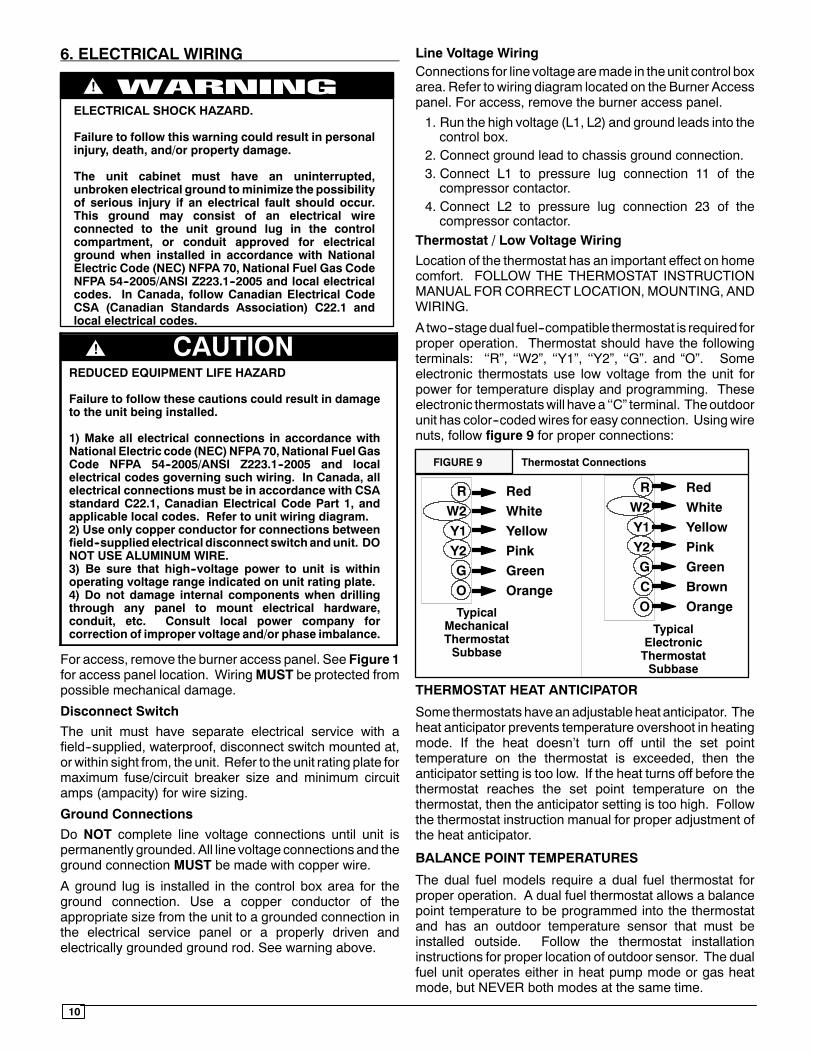
6. ELECTRICAL WIRING
ELECTRICAL SHOCK HAZARD.
Failure to follow this warning could result in personalinjury, death, and/or property damage.
The unit cabinet must have an uninterrupted,unbroken electrical ground tominimize the possibilityof serious injury if an electrical fault should occur.This ground may consist of an electrical wireconnected to the unit ground lug in the controlcompartment, or conduit approved for electricalground when installed in accordance with NationalElectric Code (NEC) NFPA 70, National Fuel Gas CodeNFPA 54--2005/ANSI Z223.1--2005 and local electricalcodes. In Canada, follow Canadian Electrical CodeCSA (Canadian Standards Association) C22.1 andlocal electrical codes.
!
REDUCED EQUIPMENT LIFE HAZARD
Failure to follow these cautions could result in damageto the unit being installed.
1) Make all electrical connections in accordance withNational Electric code (NEC)NFPA70, National FuelGasCode NFPA 54--2005/ANSI Z223.1--2005 and localelectrical codes governing such wiring. In Canada, allelectrical connections must be in accordance with CSAstandard C22.1, Canadian Electrical Code Part 1, andapplicable local codes. Refer to unit wiring diagram.2) Use only copper conductor for connections betweenfield--supplied electrical disconnect switch andunit. DONOT USE ALUMINUM WIRE.3) Be sure that high--voltage power to unit is withinoperating voltage range indicated on unit rating plate.4) Do not damage internal components when drillingthrough any panel to mount electrical hardware,conduit, etc. Consult local power company forcorrection of improper voltage and/or phase imbalance.
CAUTION!
For access, remove the burner access panel. See Figure 1for access panel location. WiringMUST be protected frompossible mechanical damage.
Disconnect Switch
The unit must have separate electrical service with afield--supplied, waterproof, disconnect switch mounted at,or within sight from, the unit. Refer to the unit rating plate formaximum fuse/circuit breaker size and minimum circuitamps (ampacity) for wire sizing.
Ground Connections
Do NOT complete line voltage connections until unit ispermanently grounded.All line voltage connections and theground connection MUST be made with copper wire.
A ground lug is installed in the control box area for theground connection. Use a copper conductor of theappropriate size from the unit to a grounded connection inthe electrical service panel or a properly driven andelectrically grounded ground rod. See warning above.
Line Voltage WiringConnections for line voltagearemade in theunit control boxarea. Refer to wiring diagram located on the Burner Accesspanel. For access, remove the burner access panel.1. Run the high voltage (L1, L2) and ground leads into thecontrol box.
2. Connect ground lead to chassis ground connection.3. Connect L1 to pressure lug connection 11 of thecompressor contactor.
4. Connect L2 to pressure lug connection 23 of thecompressor contactor.
Thermostat / Low Voltage Wiring
Location of the thermostat has an important effect on homecomfort. FOLLOW THE THERMOSTAT INSTRUCTIONMANUAL FOR CORRECT LOCATION, MOUNTING, ANDWIRING.
A two--stagedual fuel--compatible thermostat is required forproper operation. Thermostat should have the followingterminals: ‘‘R”, ‘‘W2”, ‘‘Y1”, ‘‘Y2”, ‘‘G”. and “O”. Someelectronic thermostats use low voltage from the unit forpower for temperature display and programming. Theseelectronic thermostatswill havea ‘‘C” terminal. Theoutdoorunit has color--codedwires for easy connection. Usingwirenuts, follow figure 9 for proper connections:
FIGURE 9 Thermostat Connections
RW2Y1Y2GO
TypicalMechanicalThermostatSubbase
TypicalElectronicThermostatSubbase
RedWhiteYellowPinkGreenOrange
RW2Y1Y2GCO
RedWhiteYellowPinkGreenBrownOrange
THERMOSTAT HEAT ANTICIPATOR
Some thermostats haveanadjustable heat anticipator. Theheat anticipator prevents temperature overshoot in heatingmode. If the heat doesn’t turn off until the set pointtemperature on the thermostat is exceeded, then theanticipator setting is too low. If the heat turns off before thethermostat reaches the set point temperature on thethermostat, then the anticipator setting is too high. Followthe thermostat instruction manual for proper adjustment ofthe heat anticipator.
BALANCE POINT TEMPERATURES
The dual fuel models require a dual fuel thermostat forproper operation. A dual fuel thermostat allows a balancepoint temperature to be programmed into the thermostatand has an outdoor temperature sensor that must beinstalled outside. Follow the thermostat installationinstructions for proper location of outdoor sensor. The dualfuel unit operates either in heat pump mode or gas heatmode, but NEVER both modes at the same time.
11
There are 2 different balance point temperatures toconsider when programming the thermostat: Economicand Load.
Economic Balance Point Temperature
The economic balance point temperature is the outdoortemperature where the utility cost of running in heat pumpmode is the same as running in gas heat mode. If theoutdoor temperature is above the economic balance pointtemperature, then the heat pumpmodewill be less costly. Ifthe outdoor temperature is below the economic balancepoint temperature, then the gas heat mode will be lesscostly. The economic balance point temperature is affectedby electrical utility cost, gas utility cost, and model size.
Knowing the utility cost of electricity and gas, the economicbalance point temperature can be determined usingFigure10.
Figure 10 - Economic Balance Point Temperature ChartEconomic Balance Point Temperature (°F)
CostRatio*
PDX324040
PDX330060
PDX336080
PDX342080
PDX348120
PDX360120
0.075 0 0 0 0 0 20.100 18 18 17 18 17 210.125 38 29 32 37 29 330.1375 45 35 39 45 36 380.150 52 40 45 56 43 49
* Cost Ratio is the electrical cost, in $ per kilowatt--hour, divided by the gascost, in $ per therm.
Example: A PDX342080 is installed in a residence wherethe electrical utility cost is 9 cents per kilowatt--hour and thegas cost is 90 cents per therm. Proceed as follows:1. $.09/$.90 = .12. Using Figure 10, a PDX342080 with a .1 cost ratio =>
Economic Balance Point Temperature = 18˚F
Someutilities have a sliding cost based on consumption. Inthis case, take the total bill and divide by the totalconsumption to determine the average utility cost.
Some natural gas suppliers sell gas by every 100 cubic feet(CCF) of gas. For an approximate gas cost per therm,multiply CCF by 97. Example: A price of $.01 per CCF isapproximately equivalent to $.97 per therm.
Note: The 97 multiplier is based on a typical heatingvalue of 1030 Btu per cubic foot of natural gas. For amore accurate cost, contact your gas supplier to obtainthe Btu content of natural gas in your area. Divide100,000 by the actual Btu content per cubic foot to obtainthe correct multiplier.
If the economic balance point is chosen, keep in mind thatutility rates fluctuate substantially over time. Reviewmonthly utility bills and re--calculate economic balancepoints as necessary.
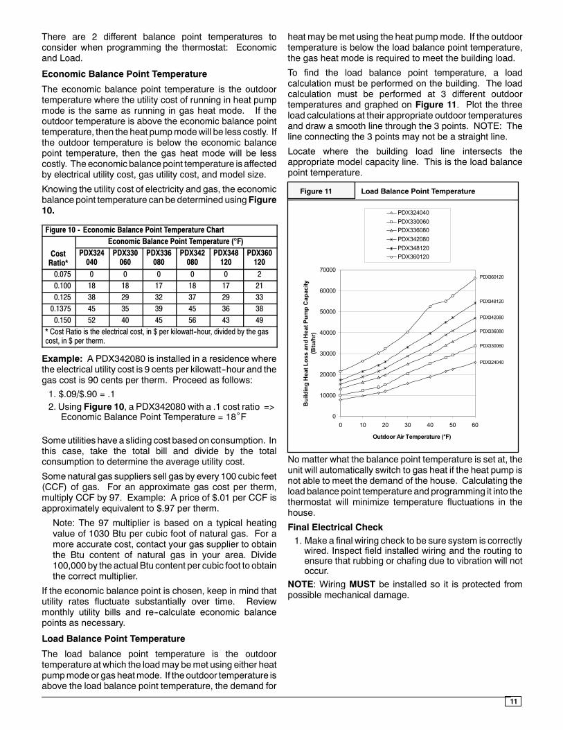
Load Balance Point Temperature
The load balance point temperature is the outdoortemperature at which the loadmay bemet using either heatpumpmodeor gas heatmode. If theoutdoor temperature isabove the load balance point temperature, the demand for
heat may be met using the heat pumpmode. If the outdoortemperature is below the load balance point temperature,the gas heat mode is required to meet the building load.
To find the load balance point temperature, a loadcalculation must be performed on the building. The loadcalculation must be performed at 3 different outdoortemperatures and graphed on Figure 11. Plot the threeload calculations at their appropriate outdoor temperaturesand draw a smooth line through the 3 points. NOTE: Theline connecting the 3 points may not be a straight line.
Locate where the building load line intersects theappropriate model capacity line. This is the load balancepoint temperature.
Figure 11 Load Balance Point Temperature
0
10000
20000
30000
40000
50000
60000
70000
0 10 20 30 40 50 60
Outdoor Air Temperature (°F)
Bui
ldin
g H
eat L
oss
and
Hea
t Pum
p C
apac
ity
(Btu
/hr)
PDX324040PDX330060PDX336080PDX342080PDX348120PDX360120
PDX324040
PDX330060
PDX342080
PDX336080
PDX348120
PDX360120
No matter what the balance point temperature is set at, theunit will automatically switch to gas heat if the heat pump isnot able to meet the demand of the house. Calculating theload balance point temperature and programming it into thethermostat will minimize temperature fluctuations in thehouse.
Final Electrical Check1. Make a final wiring check to be sure system is correctlywired. Inspect field installed wiring and the routing toensure that rubbing or chafing due to vibration will notoccur.
NOTE: Wiring MUST be installed so it is protected frompossible mechanical damage.
12
7. DUCTWORKDuctwork Sizing
Themaximum recommended velocity in trunk ducts is 1000feet per minute. The maximum recommended velocity inbranch ducts is 800 feet per minute.
Ductwork sizing affects the discharge temperature, airflowvelocity, and efficiency of the system. Be sure to properlysize ductwork to the capacity of the unit and to the airflowrequirements of the conditioned space. Failure to properlysize ductwork can result in inadequate airflow and poorefficiency. Undersized ductwork may result in tripped limitcontrols and premature failure of compressors, motors andother components.
Ductwork Insulation
Ductwork installed outdoors must have a minimum 2” thickfiberglass ”wrap” insulation and a weatherproof vaporbarrier installed around it. The insulation and vapor barriermust be protected against potential damage. Caulking,flashing, and other means of providing a permanentweather seal must be used.
Ductwork Connections
The use of flexible, non--combustible connectors betweenmain trunk ducts and supply and return air plenums is
permitted. If flexible connectors are used, they should beprotected from potential mechanical damage such aspunctures and tears.
NOTE: When connecting the supply and return plenums tothe unit, make sure that the plenums are sealed against theside casing of the unit and do not interfere with removal ofthe top of the unit.
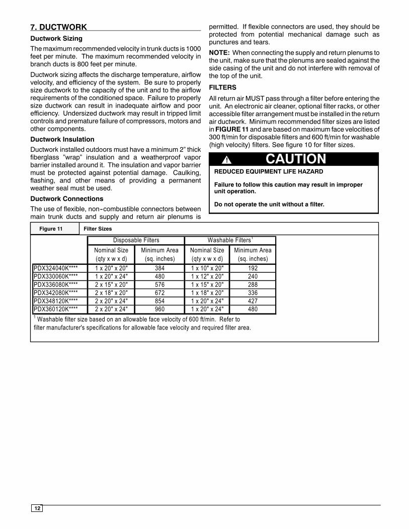
FILTERS
All return air MUST pass through a filter before entering theunit. An electronic air cleaner, optional filter racks, or otheraccessible filter arrangementmust be installed in the returnair ductwork. Minimum recommended filter sizes are listedinFIGURE11 and are based onmaximum face velocities of300 ft/min for disposable filters and 600 ft/min for washable(high velocity) filters. See figure 10 for filter sizes.
REDUCED EQUIPMENT LIFE HAZARD
Failure to follow this caution may result in improperunit operation.
Do not operate the unit without a filter.
CAUTION!
Figure 11 Filter Sizes
Nominal Size (qty x w x d)
Minimum Area (sq. inches)
Nominal Size (qty x w x d)
Minimum Area (sq. inches)
PDX324040K**** 1 x 20" x 20" 384 1 x 10" x 20" 192PDX330060K**** 1 x 20" x 24" 480 1 x 12" x 20" 240PDX336080K**** 2 x 15" x 20" 576 1 x 15" x 20" 288PDX342080K**** 2 x 18" x 20" 672 1 x 18" x 20" 336PDX348120K**** 2 x 20" x 24" 854 1 x 20" x 24" 427PDX360120K**** 2 x 20" x 24" 960 1 x 20" x 24" 4801 Washable filter size based on an allowable face velocity of 600 ft/min. Refer tofilter manufacturer's specifications for allowable face velocity and required filter area.
Disposable Filters Washable Filters1
13
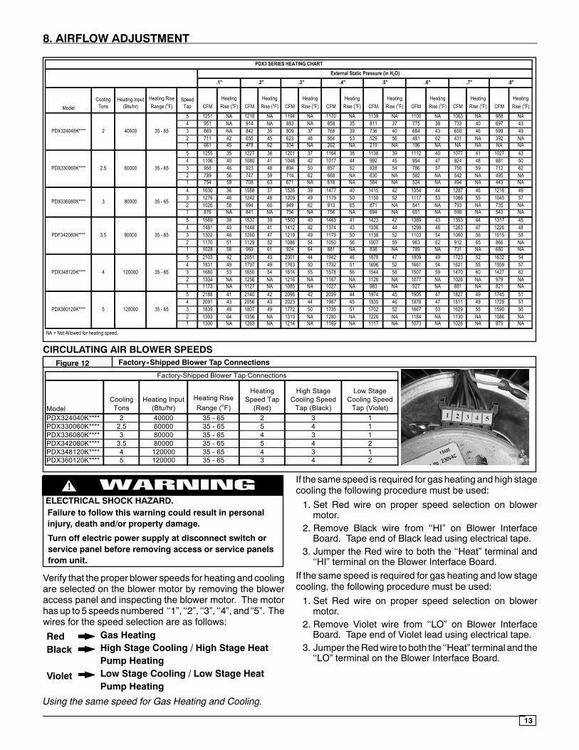
8. AIRFLOW ADJUSTMENT
ModelCooling
TonsHeating Input
(Btu/hr)Heating Rise Range (oF)
Speed Tap CFM
Heating Rise (oF) CFM
Heating Rise (oF) CFM
Heating Rise (oF) CFM
Heating Rise (oF) CFM
Heating Rise (oF) CFM
Heating Rise (oF) CFM
Heating Rise (oF) CFM
Heating Rise (oF)
5 1251 NA 1218 NA 1194 NA 1170 NA 1139 NA 1100 NA 1063 NA 988 NA4 951 NA 914 NA 883 NA 858 35 811 37 775 38 733 40 697 433 869 NA 842 35 809 37 768 39 736 40 684 43 650 46 599 492 711 42 655 45 623 48 564 53 529 56 481 62 431 NA 392 NA1 661 45 478 62 334 NA 262 NA 219 NA 196 NA NA NA NA NA5 1255 35 1227 36 1201 37 1164 38 1138 39 1112 40 1077 41 1027 434 1106 40 1080 41 1048 42 1017 44 992 45 954 47 924 48 881 503 958 46 923 48 894 50 857 52 828 54 786 57 750 59 712 622 789 56 747 59 714 62 668 NA 630 NA 582 NA 542 NA 495 NA1 754 59 708 63 671 NA 618 NA 584 NA 524 NA 494 NA 443 NA4 1630 36 1588 37 1526 39 1477 40 1415 42 1354 44 1287 46 1216 493 1276 46 1242 48 1209 49 1179 50 1150 52 1117 53 1086 55 1045 572 1026 58 994 60 949 62 913 65 871 NA 841 NA 793 NA 735 NA1 876 NA 841 NA 794 NA 756 NA 694 NA 651 NA 598 NA 543 NA5 1569 38 1537 39 1500 40 1463 41 1423 42 1389 43 1353 44 1317 454 1481 40 1448 41 1412 42 1374 43 1336 44 1298 46 1263 47 1226 483 1302 46 1260 47 1219 49 1179 50 1138 52 1103 54 1060 56 1015 582 1170 51 1129 52 1088 54 1050 56 1007 59 963 62 912 65 866 NA1 1028 58 969 61 924 64 881 NA 838 NA 789 NA 731 NA 680 NA5 2103 42 2051 43 2001 44 1942 46 1878 47 1809 49 1723 52 1632 544 1831 49 1797 49 1763 50 1732 51 1696 52 1661 54 1621 55 1559 573 1680 53 1650 54 1614 55 1578 56 1544 58 1507 59 1470 60 1427 622 1304 NA 1256 NA 1216 NA 1167 NA 1126 NA 1077 NA 1026 NA 979 NA1 1173 NA 1127 NA 1085 NA 1027 NA 983 NA 927 NA 881 NA 821 NA5 2188 41 2140 42 2096 42 2039 44 1974 45 1905 47 1827 49 1745 514 2091 43 2056 43 2023 44 1987 45 1935 46 1878 47 1811 49 1729 513 1839 48 1807 49 1772 50 1735 51 1702 52 1667 53 1629 55 1590 562 1393 64 1356 NA 1313 NA 1280 NA 1226 NA 1184 NA 1130 NA 1086 NA1 1300 NA 1263 NA 1214 NA 1169 NA 1117 NA 1073 NA 1026 NA 975 NA
NA = Not Allowed for heating speed.
External Static Pressure (in H2O)PDX3 SERIES HEATING CHART
PDX348120K**** 4 120000 35 - 65
.1" .2" .3" .4" .5" .6" .7" .8"
PDX324040K**** 2 40000 35 - 65
PDX330060K**** 2.5 60000 35 - 65
PDX336080K**** 3 80000 35 - 65
PDF342080K**** 3.5 80000 35 - 65
PDX360120K**** 5 120000 35 - 65
CIRCULATING AIR BLOWER SPEEDSFigure 12 Factory--Shipped Blower Tap Connections
ModelCooling
TonsHeating Input
(Btu/hr)Heating Rise Range (oF)
Heating Speed Tap
(Red)
High Stage Cooling Speed
Tap (Black)
Low Stage Cooling Speed
Tap (Violet)PDX324040K**** 2 40000 35 - 65 2 3 1PDX330060K**** 2.5 60000 35 - 65 5 4 1PDX336080K**** 3 80000 35 - 65 4 3 1PDX342080K**** 3.5 80000 35 - 65 5 4 2PDX348120K**** 4 120000 35 - 65 4 3 1PDX360120K**** 5 120000 35 - 65 3 4 2
Factory-Shipped Blower Tap Connections
ELECTRICAL SHOCK HAZARD.
!
Failure to follow this warning could result in personalinjury, death and/or property damage.
Turn off electric power supply at disconnect switch orservice panel before removing access or service panelsfrom unit.
Verify that the proper blower speeds for heating and coolingare selected on the blower motor by removing the bloweraccess panel and inspecting the blower motor. The motorhas up to 5 speeds numbered ‘‘1”, ‘‘2”, ‘‘3”, ‘‘4”, and “5”. Thewires for the speed selection are as follows:
Gas HeatingHigh Stage Cooling / High Stage HeatPump HeatingLow Stage Cooling / Low Stage HeatPump Heating
RedBlack
Violet
Using the same speed for Gas Heating and Cooling.
If the same speed is required for gas heating and high stagecooling the following procedure must be used:
1. Set Red wire on proper speed selection on blowermotor.
2. Remove Black wire from ‘‘HI” on Blower InterfaceBoard. Tape end of Black lead using electrical tape.
3. Jumper the Red wire to both the ‘‘Heat” terminal and‘‘HI” terminal on the Blower Interface Board.
If the same speed is required for gas heating and low stagecooling, the following procedure must be used:1. Set Red wire on proper speed selection on blowermotor.
2. Remove Violet wire from ‘‘LO” on Blower InterfaceBoard. Tape end of Violet lead using electrical tape.
3. Jumper theRedwire to both the ‘‘Heat” terminal and the‘‘LO” terminal on the Blower Interface Board.
14
CONTINUOUS FAN OPERATION
Continuous fan speed operates at the low stage coolingspeed for all models.
COOLING
1. Turn electric power OFF2. Set thermostat Heat--Cool select to COOL.3. Adjust thermostat setting to below room temperature.4. Turn power ON, for approximately one minute, thenOFF. During power application check the following:a. Contactor -- Contacts Closingb. Compressor -- ONc. Condenser fan motor -- ONd. Circulating Air Blower -- ON 0 second delay
5. Turn power OFF, check the following:a. Contactor contacts opening.b. Compressor -- OFFc. Condenser fan motor -- OFFd. Circulating blower -- OFF after 90 second delay on
all models.
9. START--UP PROCEDURES
FIRE OR EXPLOSION HAZARD
Failure to follow this warning could result in personalinjury, death and/or property damage.
Do NOT attempt to light the burner with a match orflame of any kind.
!
CHECK BEFORE STARTING
1. Check that the blower motor speed terminal block isrunning the correct heating and cooling speeds.
2. Check to see that clean, properly sized air filters areinstalled.
3. Replace all service access panels.
FIRE OR EXPLOSION HAZARD.
Failure to follow this warning could result inpersonal injury and/or death.
Turn OFF gas at shut off before connecting U--tubemanometer.
!
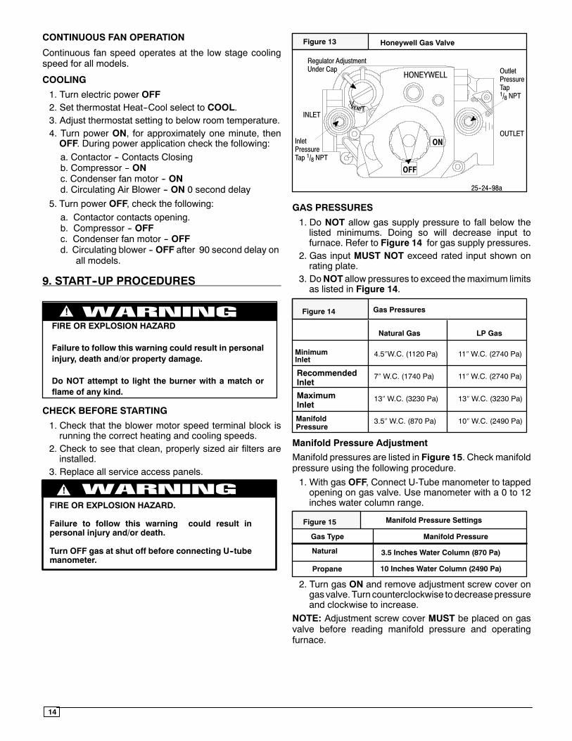
Honeywell Gas Valve
VT
25--24--98a
HONEYWELL
ON
OFF
Regulator AdjustmentUnder Cap
InletPressureTap 1/8 NPT
INLET
OUTLET
OutletPressureTap1/8 NPT
Figure 13
GAS PRESSURES
1. Do NOT allow gas supply pressure to fall below thelisted minimums. Doing so will decrease input tofurnace. Refer to Figure 14 for gas supply pressures.
2. Gas input MUST NOT exceed rated input shown onrating plate.
3. DoNOT allow pressures to exceed themaximum limitsas listed in Figure 14.
4.5″W.C. (1120 Pa) 11″W.C. (2740 Pa)
7″W.C. (1740 Pa) 11″W.C. (2740 Pa)
13″W.C. (3230 Pa) 13″W.C. (3230 Pa)
3.5″W.C. (870 Pa) 10″W.C. (2490 Pa)
Gas Pressures
Natural Gas LP Gas
RecommendedInlet
ManifoldPressure
MinimumInlet
MaximumInlet
Figure 14
Manifold Pressure Adjustment
Manifold pressures are listed in Figure 15. Check manifoldpressure using the following procedure.1. With gas OFF, Connect U-Tube manometer to tappedopening on gas valve. Use manometer with a 0 to 12inches water column range.
Manifold Pressure Settings
Gas Type Manifold Pressure
Natural
Propane
3.5 Inches Water Column (870 Pa)
10 Inches Water Column (2490 Pa)
Figure 15
2. Turn gas ON and remove adjustment screw cover ongasvalve.Turn counterclockwise todecreasepressureand clockwise to increase.
NOTE: Adjustment screw cover MUST be placed on gasvalve before reading manifold pressure and operatingfurnace.
15
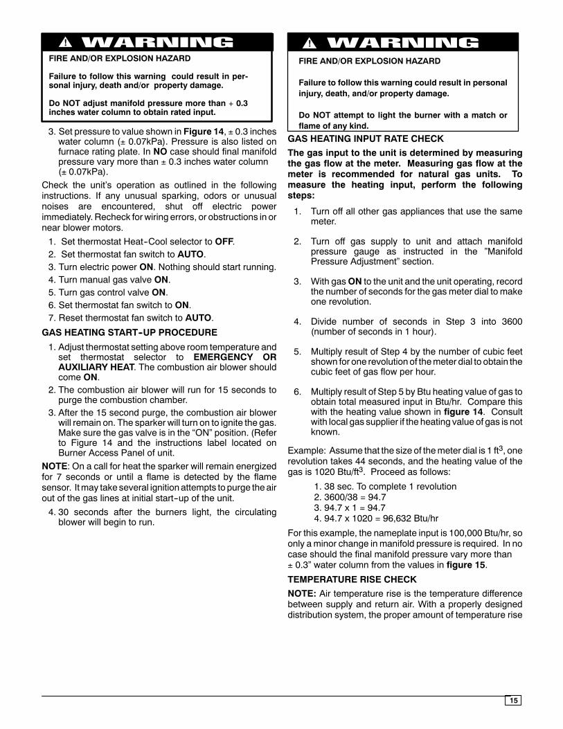
FIRE AND/OR EXPLOSION HAZARD
Failure to follow this warning could result in per-sonal injury, death and/or property damage.
Do NOT adjust manifold pressure more than + 0.3inches water column to obtain rated input.
!
3. Set pressure to value shown in Figure 14, ± 0.3 incheswater column (± 0.07kPa). Pressure is also listed onfurnace rating plate. In NO case should final manifoldpressure vary more than ± 0.3 inches water column(± 0.07kPa).
Check the unit’s operation as outlined in the followinginstructions. If any unusual sparking, odors or unusualnoises are encountered, shut off electric powerimmediately. Recheck for wiring errors, or obstructions in ornear blower motors.1. Set thermostat Heat--Cool selector to OFF.2. Set thermostat fan switch to AUTO.3. Turn electric power ON. Nothing should start running.4. Turn manual gas valve ON.5. Turn gas control valve ON.6. Set thermostat fan switch to ON.7. Reset thermostat fan switch to AUTO.
GAS HEATING START--UP PROCEDURE
1. Adjust thermostat setting above room temperature andset thermostat selector to EMERGENCY ORAUXILIARY HEAT. The combustion air blower shouldcome ON.
2. The combustion air blower will run for 15 seconds topurge the combustion chamber.
3. After the 15 second purge, the combustion air blowerwill remain on. The sparker will turn on to ignite the gas.Make sure the gas valve is in the “ON” position. (Referto Figure 14 and the instructions label located onBurner Access Panel of unit.
NOTE: On a call for heat the sparker will remain energizedfor 7 seconds or until a flame is detected by the flamesensor. Itmay take several ignition attempts to purge theairout of the gas lines at initial start--up of the unit.4. 30 seconds after the burners light, the circulatingblower will begin to run.
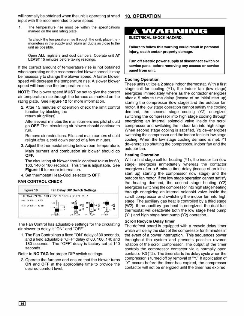
FIRE AND/OR EXPLOSION HAZARD
Failure to follow this warning could result in personalinjury, death, and/or property damage.
Do NOT attempt to light the burner with a match orflame of any kind.
!
GAS HEATING INPUT RATE CHECK
The gas input to the unit is determined by measuringthe gas flow at the meter. Measuring gas flow at themeter is recommended for natural gas units. Tomeasure the heating input, perform the followingsteps:
1. Turn off all other gas appliances that use the samemeter.
2. Turn off gas supply to unit and attach manifoldpressure gauge as instructed in the ”ManifoldPressure Adjustment” section.
3. With gasON to the unit and the unit operating, recordthe number of seconds for the gas meter dial to makeone revolution.
4. Divide number of seconds in Step 3 into 3600(number of seconds in 1 hour).
5. Multiply result of Step 4 by the number of cubic feetshown for one revolutionof themeter dial to obtain thecubic feet of gas flow per hour.
6. Multiply result of Step 5 by Btu heating value of gas toobtain total measured input in Btu/hr. Compare thiswith the heating value shown in figure 14. Consultwith local gas supplier if the heating value of gas is notknown.
Example: Assume that the size of themeter dial is 1 ft3, onerevolution takes 44 seconds, and the heating value of thegas is 1020 Btu/ft3. Proceed as follows:
1. 38 sec. To complete 1 revolution2. 3600/38 = 94.73. 94.7 x 1 = 94.74. 94.7 x 1020 = 96,632 Btu/hr
For this example, the nameplate input is 100,000 Btu/hr, soonly aminor change in manifold pressure is required. In nocase should the final manifold pressure vary more than± 0.3” water column from the values in figure 15.
TEMPERATURE RISE CHECK
NOTE: Air temperature rise is the temperature differencebetween supply and return air. With a properly designeddistribution system, the proper amount of temperature rise
16
will normally be obtained when the unit is operating at ratedinput with the recommended blower speed.
1. The temperature rise must be within the specificationsmarked on the unit rating plate.
To check the temperature rise through the unit, place ther-mometers in the supply and return air ducts as close to theunit as possible.
Open ALL registers and duct dampers. Operate unit ATLEAST 15 minutes before taking readings.
If the correct amount of temperature rise is not obtainedwhen operating on the recommended blower speed, it maybe necessary to change the blower speed. A faster blowerspeed will decrease the temperature rise. A slower blowerspeed will increase the temperature rise.
NOTE: The blower speed MUST be set to give the correctair temperature rise through the furnace as marked on therating plate. See Figure 12 for more information.
2. After 15 minutes of operation check the limit controlfunction by blocking thereturn air grille(s).After severalminutes themain burners and pilot shouldgo OFF. The circulating air blower should continue torun.Remove air restrictions. Pilot and main burners shouldrelight after a cool down period of a few minutes.
3. Adjust the thermostat setting below room temperature.Main burners and combustion air blower should goOFF.The circulating air blower should continue to run for 60,100, 140 or 180 seconds. This time is adjustable. SeeFigure 16 for more information.
4. Set thermostat Heat--Cool selector to OFF.
FAN CONTROL CHECK
Fan Delay DIP Switch SettingsFigure 16
The Fan Control has adjustable settings for the circulatingair blower to delay it ‘‘ON’’ and ‘‘OFF’’.1. The Fan Control has a fixed ‘‘ON” delay of 30 seconds,and a field adjustable ‘‘OFF” delay of 60, 100, 140 and180 seconds. The ‘‘OFF” delay is factory set at 140seconds.
Refer to NO TAG for proper DIP switch settings.2. Operate the furnace and ensure that the blower turnsON and OFF at the appropriate time to provide thedesired comfort level.
10. OPERATION
ELECTRICAL SHOCK HAZARD.
Failure to follow this warning could result in personalinjury, death and/or property damage.
Turn off electric power supply at disconnect switch orservice panel before removing any access or servicepanel from unit.
!
Cooling OperationThese units utilize a 2 stage indoor thermostat. With a firststage call for cooling (Y1), the indoor fan (low stage)energizes immediately where as the contactor energizesafter a 5 minute time delay (incase of an initial start up)starting the compressor (low stage) and the outdoor fanmotor. If the low stage operation cannot satisfy the coolingdemand, the second stage cooling (Y2) energizesswitching the compressor into high stage cooling throughenergizing an internal solenoid valve inside the scrollcompressor and switching the indoor fan into high stage.When second stage cooling is satisfied, Y2 de--energizesswitching the compressor and the indoor fan into low stagecooling. When the low stage cooling demand is met, Y1de--energizes shutting the compressor, indoor fan and theoutdoor fan.
Heating OperationWith a first stage call for heating (Y1), the indoor fan (lowstage) energizes immediately whereas the contactorenergizes after a 5 minute time delay (incase of an initialstart up) starting the compressor (low stage) and theoutdoor fan motor. If the low stage operation cannot satisfythe heating demand, the second stage heating (Y2)energizes switching the compressor into high stageheatingthrough energizing an internal solenoid valve inside thescroll compressor and switching the indoor fan into highstage. The auxiliary gas heat is controlled by a third stage(W2). If the auxiliary gas heat is energized, the dual fuelthermostat will deactivate both the low stage heat pump(Y1) and high stage heat pump (Y2) operation.
Scroll Recycle Delay timerThe defrost board is equipped with a recycle delay timerwhich will delay the start of the compressor for 5 minutes inthe event of a power interruption. This sequences powerthroughout the system and prevents possible reverserotation of the scroll compressor. The output of the timercontrols the compressor contactor via a normally opencontact ofK3 (T2). The timer starts thedelay cyclewhen thecompressor is turned off by removal of ‘‘Y.” If application of‘‘Y” occurs before the timer has expired, the compressorcontactor will not be energized until the timer has expired.
17
CONTINUOUS FAN OPERATION
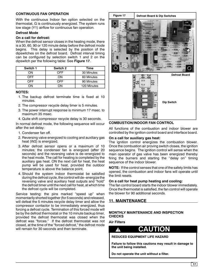
With the continuous Indoor fan option selected on thethermostat, G is continuously energized. The system runslow stage (Y1) airflow for continuous fan operation.Defrost ModeOn a call for defrost:When the defrost sensor closes in the heating mode, thereis a 30, 60, 90 or 120 minute delay before the defrost modebegins. This delay is selected by the position of thedipswitches on the defrost board. Defrost interval timingcan be configured by selection switch 1 and 2 on thedipswitch per the following table: See Figure 17.
Switch 1 Switch 2 TimeON OFF 30 MinutesOFF ON 60 MinutesOFF OFF 90 MinutesON ON 120 Minutes
NOTES:1. The backup defrost terminate time is fixed at 10minutes.
2. The compressor recycle delay timer is 5 minutes.3. The power interrupt response is minimum 17 msec. tomaximum 35 msec.
4. Quite shift compressor recycle delay is 30 seconds.In normal defrost mode, the following sequence will occurafter the set delay:1. Condenser fan off.2. Reversing valve energized to cooling and auxiliary gasheat (W2) is energized.
3. After defrost sensor opens or a maximum of 10minutes; the condenser fan is energized (after 20seconds) and the reversing valve is de--energized tothe heat mode. The call for heating is completed by theauxiliary gas heat. ON the next call for heat, the heatpump will be used for heat, provided the outdoortemperature is above the balance point.
4. Should the system indoor thermostat be satisfiedduring thedefrost cycle, the controlwill de--energize thereversing valve and auxiliary heat outputs and ”hold”thedefrost timer until the next call for heat, atwhich timethe defrost cycle will be completed.
Service testing: the pins marked “speed up” whenmomentarily shorted together (for 5 seconds) and released,will defeat the 5 minutes recycle delay timer and allow thecompressor contactor to be immediately energized, thusforcing a defrost cycle. Termination of this forced mode willbe by the defrost thermostat or the 10minute backup timer,provided the defrost thermostat was closed when thedefrost was “forces.” If the defrost thermostat was notclosed, at the time of the “forced defrost,” the defrost modewill remain for 30 seconds and then terminate.
Defrost Board & Dip Switches
Defrost Board
Dip Switch
Figure 17
COMBUSTION/INDOOR FAN CONTROL
All functions of the combustion and indoor blower arecontrolled by the ignition control board and interface board.
On a call for auxiliary gas heat:The ignition control energizes the combustion blower.Once the combustion air proving switch closes, the ignitionsequence begins. The ignition control will sense when themain operator of gas valve has been energized therebyfiring the burners and starting the ‘‘delay on’’ timingsequence of the indoor blower.
NOTE: If the control senses that one of the safety limits hasopened, the combustion and indoor fans will operate untilthe limit resets.
On a call for heat pump heating and cooling:The fan control board starts the indoor blower immediately.Once the thermostat is satisfied, the fan control will operatethe blower for 90 additional seconds.
11. MAINTENANCE
MONTHLY MAINTENANCE AND INSPECTIONCHECKS
Air Filters
REDUCED EQUIPMENT LIFE HAZARD
Failure to follow this cautions may result in damage tothe unit being installed.
Do not operate the unit without a filter.
CAUTION!
18
Inspect filters at least monthly and replace or clean asrequired. Washable filters may be cleaned by soaking inmild detergent and rinsing with cold water. Replace filterswith the arrows on the side pointing in the direction of airflow. Dirty filters are themost common cause of inadequateheating or cooling performance, and of compressorfailures.
HEATING SEASON CHECKS (MONTHLY)
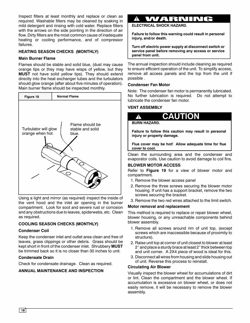
Main Burner Flame
Flames should be stable and solid blue, (dust may causeorange tips or they may have wisps of yellow, but theyMUST not have solid yellow tips). They should extenddirectly into the heat exchanger tubes and the turbulatorsshould glow orange (after about five minutes of operation).Main burner flame should be inspected monthly.
Normal Flame
Turbulator will gloworange when hot.
Flame should bestable and solidblue.
Figure 18
Using a light and mirror (as required) inspect the inside ofthe vent hood and the inlet air opening in the burnercompartment. Look for soot and severe rust or corrosionand any obstructions due to leaves, spiderwebs, etc. Cleanas required.
COOLING SEASON CHECKS (MONTHLY)
Condenser Coil
Keep the condenser inlet and outlet area clean and free ofleaves, grass clippings or other debris. Grass should bekept short in front of the condenser inlet. ShrubberyMUSTbe trimmed back so it is no closer than 30 inches to unit.
Condensate Drain
Check for condensate drainage. Clean as required.
ANNUAL MAINTENANCE AND INSPECTION
ELECTRICAL SHOCK HAZARD.
Failure to follow this warning could result in personalinjury, and/or death.
Turn off electric power supply at disconnect switch orservice panel before removing any access or servicepanel from unit.
!
The annual inspection should include cleaning as requiredto ensure efficient operation of the unit. To simplify access,remove all access panels and the top from the unit ifpossible .
Condenser Fan Motor
Note: The condenser fan motor is permanently lubricated.No further lubrication is required. Do not attempt tolubricate the condenser fan motor.
VENT ASSEMBLY
CAUTION!BURN HAZARD.
Failure to follow this caution may result in personalinjury or property damage.
Flue cover may be hot! Allow adequate time for fluecover to cool.
Clean the surrounding area and the condenser andevaporator coils. Use caution to avoid damage to coil fins.
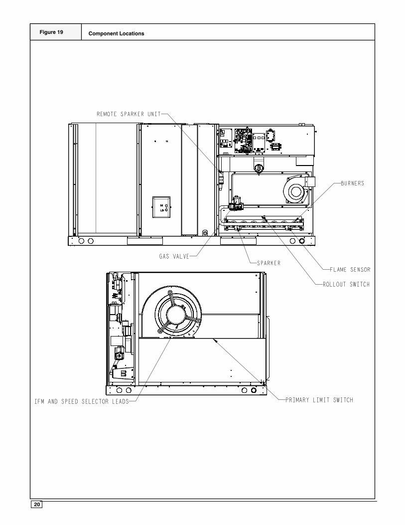
BLOWER MOTOR ACCESSRefer to Figure 19 for a view of blower motor andcompartment.1. Remove the blower access panel2. Remove the three screws securing the blower motorhousing. If unit has a support bracket, remove the twoscrews securing the bracket.
3. Remove the two red wires attached to the limit switch.Motor removal and replacement
This method is required to replace or repair blower wheel,blower housing, or any unreachable components behindblower assembly.
1. Remove all screws around rim of unit top, (exceptscrews which are inaccessible because of proximity tostructure).
2. Raise unit top at corner of unit closest to blower at least2″andplacea sturdybraceat least 2″ thick between topand unit corner. A 2X4 piece of wood is ideal for this.
3. Disconnect allwires fromhousingandslidehousingoutof unit. Reverse this process to reinstall.
Circulating Air Blower
Visually inspect the blower wheel for accumulations of dirtor lint. Clean the compartment and the blower wheel. Ifaccumulation is excessive on blower wheel, or does noteasily remove, it will be necessary to remove the blowerassembly.
19
Note: The blower motor is permanently lubricated. Nofurther lubrication is required. Do not attempt to lubricatethe blower motor.
Burners / Heat Exchangers / Flue Gas Passages
To inspect the burners, heat exchanger and interior flue gaspassages, use a light and small mirror on an extensionhandle.
Check the exterior of the heat exchanger and the interiorflue gas passages for any evidence of deterioration due tocorrosion, cracking or other causes. If signs of scaling orsooting exist, remove the burners and clean the heatexchanger, as required.
INSPECTION AND CLEANING OF BURNERASSEMBLY/HEAT EXCHANGERS/FLUE GASPASSAGES
For Qualified Service Technician Only
See Figure 19 for identification of parts.1. Disconnect electrical power to unit.2. Turn OFF gas at manual shut off valve.3. Remove burner access panel.4. Remove the vent assembly flue pipe.5. Disconnect gas pipe at union.6. Disconnect wires from gas valve, note connections.7. Remove screws that secure the flame shield andremove gas control valve, manifold and burners as anassembly.
8. Remove collector box, injector plate, and restrictorplate, including gaskets.
9. Hold the burner assembly vertically and lightly tap itagainst a wood block. Clean also with a stiff brush.Severe cases of lint clogging may require washing theburners in hot water.
10. Clean fluegaspassagesbyusingsmall brushesandavacuum cleaner. It may be necessary to fabricatehandle extensions for the brushes to reach the areasthat require cleaning. Reinspect after cleaning andreplace the heat exchanger if defective.
11. Reinstall parts and gaskets in reverse order. On directspark models check the spark gap. 1/8 inch is requiredbetween the sparker electrodes.
12. Turn gas on and check for leaks.13. Install all access panels, turn power on and check fornormal operation.
REFRIGERANT CIRCUIT
For Qualified Service Technician Only
Annually inspect all refrigerant tubing connections and theunit base for oil accumulations. Detecting oil generallyindicates a refrigerant leak.
ENVIRONMENTAL HAZARD.
Failure to follow this warning could result in personalinjury, death and/or property damage.
Systemunder pressure. Relieve pressure and recoverall refrigerant before system repair or final unitdisposal. Use all service ports and open all flowcontrol devices, including solenoid valves.
Federal regulations require that you do not ventrefrigerant to atmosphere. Recover during systemrepair or final unit disposal
!
If oil is detected or if low cooling performance is suspected,leak--test all refrigerant tubing using an electronic leakdetector, halide torch, or liquid--soap solution.
20
Component LocationsFigure 19
21
12. Rigging Instructions
FIGURE 10 Rigging Instructions
22
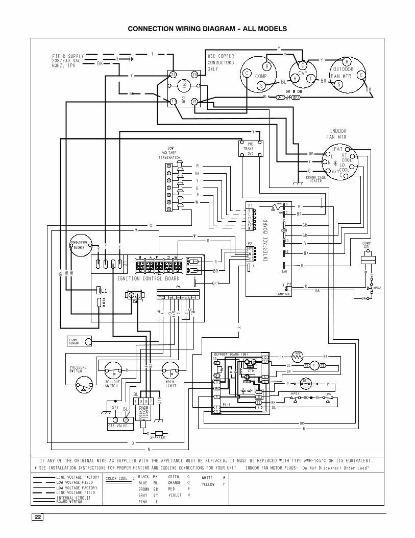
CONNECTION WIRING DIAGRAM -- ALL MODELS
23
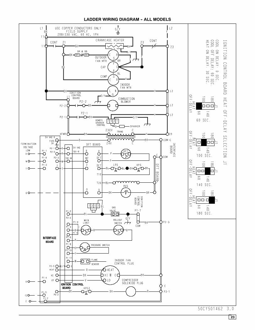
LADDER WIRING DIAGRAM -- ALL MODELS