Embed Size (px)
Citation preview

to theexpe_
Installation Instructions
NOTE: Read the entire instruction manual before startingthe installation
TABLE OF CONTENTS
SAFETY CONSIDERATIONS .................... 1
INSTALLATION ............................... 4
Step 1 - Plan for Unit Location .................. 4
Step 2 - Plan for Sequence of Unit Installation ...... 5
Step 3 - Inspect Unit ........................... 5
Step 4 - Provide Unit Support ................... 5
Step 5 - Field Fabricate Ductwork ................ 7
Step 6 - Rig and Place Unit ..................... 7
Step 7 - Convert to Horizontal & Connect Ductwork . 8
Step 8 - Install Outside Air Hood ................ 9
Step 9 - Install External Condensate Trap and Line . 10
Step 10 - Make Electrical Connections ........... 11
Step 11 - Adjust Factory-Installed Options ........ 39
Step 12 - Install Accessories ................... 39
SAFETY CONSIDERATIONS
Improper installation, adjustment, alteration, service,
maintenance, or use can cause explosion, fire, electricalshock or other conditions which may cause personal
injury or property damage. Consult a qualified installer,
service agency, or your distributor or branch forinformation or assistance. The qualified installer or
agency must use factory-authorized kits or accessorieswhen modifying this product. Refer to the individual
instructions packaged with the kits or accessories wheninstalling.
Follow all safety codes. Wear safety glasses and work
gloves. Use quenching cloths for brazing operations andhave a fire extinguisher available. Read these instructions
thoroughly and follow all warnings or cautions attached tothe unit. Consult local building codes and appropriate
national electrical codes (in USA, ANSI/NFPA70,
National Electrical Code (NEC); in Canada, CSA C22.1)for special requirements.
It is important to recognize safety information. This is the
safety-alert symbol AX. When you see this symbol on theunit and in instructions or manuals, be alert to thepotential for personal injury.
Understand the signal words DANGER, WARNING,CAUTION, and NOTE. These words are used with the
safety-alert symbol. DANGER identifies the most serious
hazards which will result in severe personal injury ordeath. WARNING signifies hazards which could result in
personal injury or death. CAUTION is used to identifyunsafe practices, which may result in minor personal
injury or product and property damage. NOTE is used tohighlight suggestions which will result in enhanced
installation, reliability, or operation.
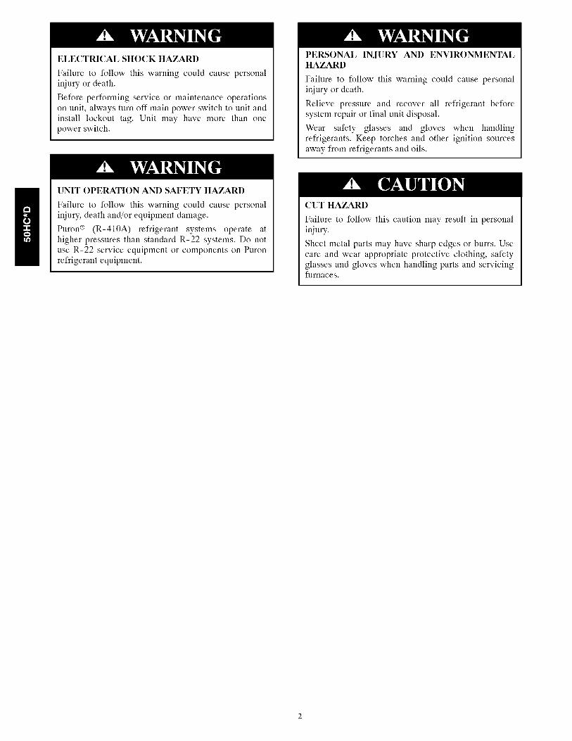
ELECTRICALSHOCKHAZARDFailure to follow this warning could cause personalinjury or death.
Before performing service or maintenance operationson unit, always turn off main power switch to unit andinstall lockout tag. Unit may have more than onepower switch.
PERSONAL INJURY AND ENVIRONMENTALHAZARD
Failure to follow this warning could cause personalinjury or death.
Relieve pressure and recover all refrigerant beforesystem repair or final unit disposal.
Wear safety glasses and gloves when handlingrefrigerants. Keep torches and other ignition sourcesaway from refrigerants and oils.
UNIT OPERATION AND SAFETY HAZARD
Failure to follow this warning could cause personalinjury, death and/or equipment damage.
Puron ® (R-410A) refrigerant systems operate athigher pressures than standard R-22 systems. Do notuse R-22 service equipment or components on Puronrefrigerant equipment.
CUT HAZARD
Failure to follow this caution may result in personalinjury.
Sheet metal parts may have sharp edges or burrs. Use
care and wear appropriate protective clothing, safetyglasses and gloves when handling parts and servicingfurnaces.
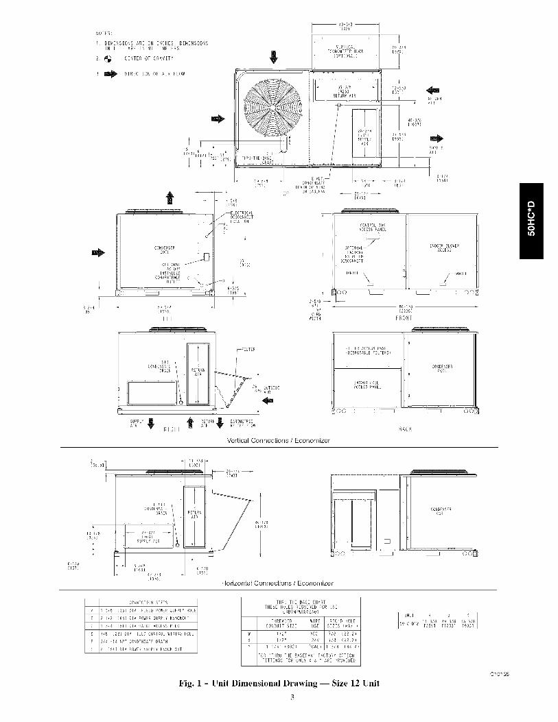
NOTES:
I DIMENSIONS ARE IN INCHES, DIMENSIONSIN [ ] ARE IN MILLIMETERS
2 _ CENTER OF GRAVITY
3 _ DIRECTION OF AIR FLOW
3 3/4 9
[95]
CONDENSERCOIL
OPTIONAL_FACTORY
INSTALLEDCONVENIENCE C--
OUTLET'0
59 1/2[1510]
LEFT
_ !=__,,',,,,¢_\,_<_
SEE_THRU THE BASE......... CHA£
29 5/D
18 16[469] 14 11
[_12] 355 [279]
4 518
[I18]
ELECTRICAL_DISCOKNECT
LOCATION
B,
G
56[913]
40 BID[1026]
VERTICALECONOMIZER HOOD
(OPTIONAL)
IT .....
, RETURNAIR
E ALT J
CONDENSATE[751] DRAIN OPENING
TOP IN BASEPAN
t20 3/4[526]
12 5/8[321]
40 S/8[1027]
RETURNAIR
SUPPLYAIR
[159]
2 518[67]
TYPCURS
WIDTH
CONTROLSONACCESS PANEL
OPTIONALJFACTORY
INSTALLEDDISCONNECT
INDOOR BLOWER
ACCESS
88 }/8[R238]
FRONT
ESTS_ "_
/
SUPPLY _ t RETURN _ UARONETRICAIR RIGHT AIR RELIEF FLOW
FILTER ACCESS PANELIDISPOSABLE FILTERS)
INDOOR COIL
ACCESS PANEL
CONDENSERCOIL
_60 ' • E:::_" ........ E::_" bC
BACK
Vertical Connections / Economizer
!i
_50 RIB
CONDER_E_SPAIN 1
L[/68]
42 3/8_[/076]
1S 1/8[334]
t
I6 I/8 _
[157]
CONNECTION SIZES
A 1 3/8" [35] DIA FIELD POWER SUPPLY HOLE
B 2 I/2" [64] DIA POWER SUPPLY KNOCKOUT
C I B/_" [51] DIA GAUGE ACCESS PLUG
D 718" [22] DIA FIELD CONTROL WIRING HOLE
E 314" 14 NPT CONDENSATE DRAIN
G 2" [51] DIA POWERSUPPLY KNOCK OUT
11 7/8 I_[sos] I
S 1/8
[155]
Horizontal Connections / Economizer
CONDENSERCOIL
E_' oo[
THRU THE BASE CHARTTHESE HOLES REQUIRED FOR USE
CRBTMPWROO2AOl
THREADED WIRE REQ'B HOLECONDUIT SIZE USE SIZES (MAX)
W I/2" ACC 718" (222)
X 1/2" 24V 7/8" (222)
Y 1 1/411 (DO2) POWER 3/411 (444)
FOR "THRU THE BASEPAN" FACTORY OPTION,FITTINGS FOR ONLY X & Y ARE PROVIDED
Fig. 1 - Unit Dimensional Drawing -- Size 12 Unit
3
010155
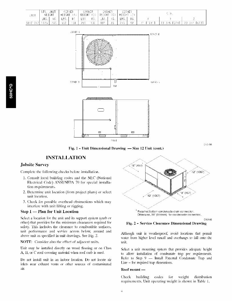
STD, UNIT CORNER CORNER CORNER CORNERUNIT WEIGHT WEIGHT (A) WEIGHT (B) WEIGHT (C) WEIGHT (D) C.G.
LBS. KG. LBS. KG. LBS. KG. LBS, KG, LBS. KG. X Y Z
50HC-DS2 1025 465 333 151 290 132 187 85 215 98 41 [1041] 23 3/8 [594] 23 3/4 [605]
CORNER A
CORNER D
11 _ -- _ CORNERB
_s _,',,_S;_
CORNERC
z
I r_ r_
• ooi
Fig. 1 - Unit Dimensional Drawing -- Size 12 Unit (cont.)C10156
INSTALLATION
Jobsite Survey
Complete the following checks before installation.
1. Consult local building codes and the NEC (National
Electrical Code) ANSI/NFPA 70 for special installa-tion requirements.
2. Determine unit location (from project plans) or selectunit location.
3. Check for possible overhead obstructions which mayinterfere with unit lifting or rigging.
Step 1 -- Plan for Unit Location
Select a location for the unit and its support system (curb orother) that provides for the minimum clearances required for
safety. This includes the clearance to combustible surfaces,unit performance and service access below, around and
above unit as specified in unit drawings. See Fig. 2.
NOTE: Consider also the effect of adjacent units.
Unit may be installed directly on wood flooring or on ClassA, B, or C roof-covering material when roof curb is used.
Do not install unit in an indoor location. Do not locate air
inlets near exhaust vents or other sources of contaminatedair.
<- ,_42" (1067)
.... j.
Required bottom condensate drain connection•
Otherwise, 36" (914mm) for condensate connection•
C10145
Fig. 2 I Service Clearance Dimensional Drawing
Although unit is weatherproof, avoid locations that permit
water from higher level runoff and overhangs to fall onto theunit.
Select a unit mounting system that provides adequate heightto allow installation of condensate trap per requirements.
Refer to Step 9 -- Install External Condensate Trap and
Line - for required trap dimensions.
Roof mount --
Check building codes for weight distribution
requirements. Unit operating weight is shown in Table 1.
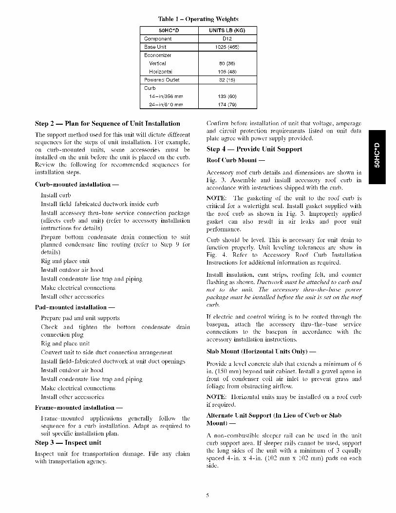
Table 1 - Operating Weights
60HC*D UNITS LB (KG)
Component D12
Base Unit 1025 (465)
Economizer
Vertical 80 (36)
Horizontal 105 (48)
Powered Outlet 32 (15)
Curb
14-in/356 mm 133 (60)
24-in/610 mm 174 (79)
Step 2 -- Plan for Sequence of Unit Installation
The support method used for this unit will dictate differentsequences for the steps of unit installation. For example,on curb-mounted units, some accessories must be
installed on the unit before the unit is placed on the curb.Review the following for recommended sequences forinstallation steps.
Curb-mounted installation --
Install curb
Install field-fabricated ductwork inside curb
Install accessory thru-base service connection package(affects curb and unit) (refer to accessory installationinstructions for details)
Prepare bottom condensate drain connection to suitplanned condensate line routing (refer to Step 9 fordetails)
Rig and place unitInstall outdoor air hood
Install condensate line trap and pipingMake electrical connections
Install other accessories
Pad-mounted installation --
Prepare pad and unit supports
Check and tighten the bottom condensate drainconnection plug
Rig and place unit
Convert unit to side duct connection arrangement
Install field-fabricated ductwork at unit duct openingsInstall outdoor air hood
Install condensate line trap and pipingMake electrical connections
Install other accessories
Frame-mounted installation --
Frame-mounted applications generally follow thesequence for a curb installation. Adapt as required tosuit specific installation plan.
Step 3 -- Inspect unit
Inspect unit for transportation damage. File any claimwith transportation agency.
Confirm before installation of unit that voltage, amperageand circuit protection requirements listed on unit dataplate agree with power supply provided.
Step 4 -- Provide Unit Support
Roof Curb Mount --
Accessory roof curb details and dimensions are shown inFig. 3. Assemble and install accessory roof curb inaccordance with instructions shipped with the curb.
NOTE: The gasketing of the unit to the roof curb iscritical for a watertight seal. Install gasket supplied withthe roof curb as shown in Fig. 3. Improperly appliedgasket can also result in air leaks and poor unitperformance.
Curb should be level. This is necessary for unit drain tofunction properly. Unit leveling tolerances are show inFig. 4. Refer to Accessory Roof Curb InstallationInstructions for additional information as required.
Install insulation, cant strips, roofing felt, and counterflashing as shown. Ductwork must be attached to curb andnot to the unit. The accessory thru-the-base powerpackage must be installed before the unit is"set on the roofcurb.
If electric and control wiring is to be routed through thebasepan, attach the accessory thru-the-base serviceconnections to the basepan in accordance with theaccessory installation instructions.
Slab Mount (Horizontal Units Only) --
Provide a level concrete slab that extends a minimum of 6
in. (150 mm) beyond unit cabinet. Install a gravel apron in
front of condenser coil air inlet to prevent grass andfoliage from obstructing airflow.
NOTE: Horizontal units may be installed on a roof curb
if required.
Alternate Unit Support (In Lieu of Curb or SlabMount) --
A non-combustible sleeper rail can be used in the unitcurb support area. If sleeper rails cannot be used, supportthe long sides of the unit with a minimum of 3 equallyspaced 4-in. x 4-in. (102 mm x 102 mm) pads on eachside.
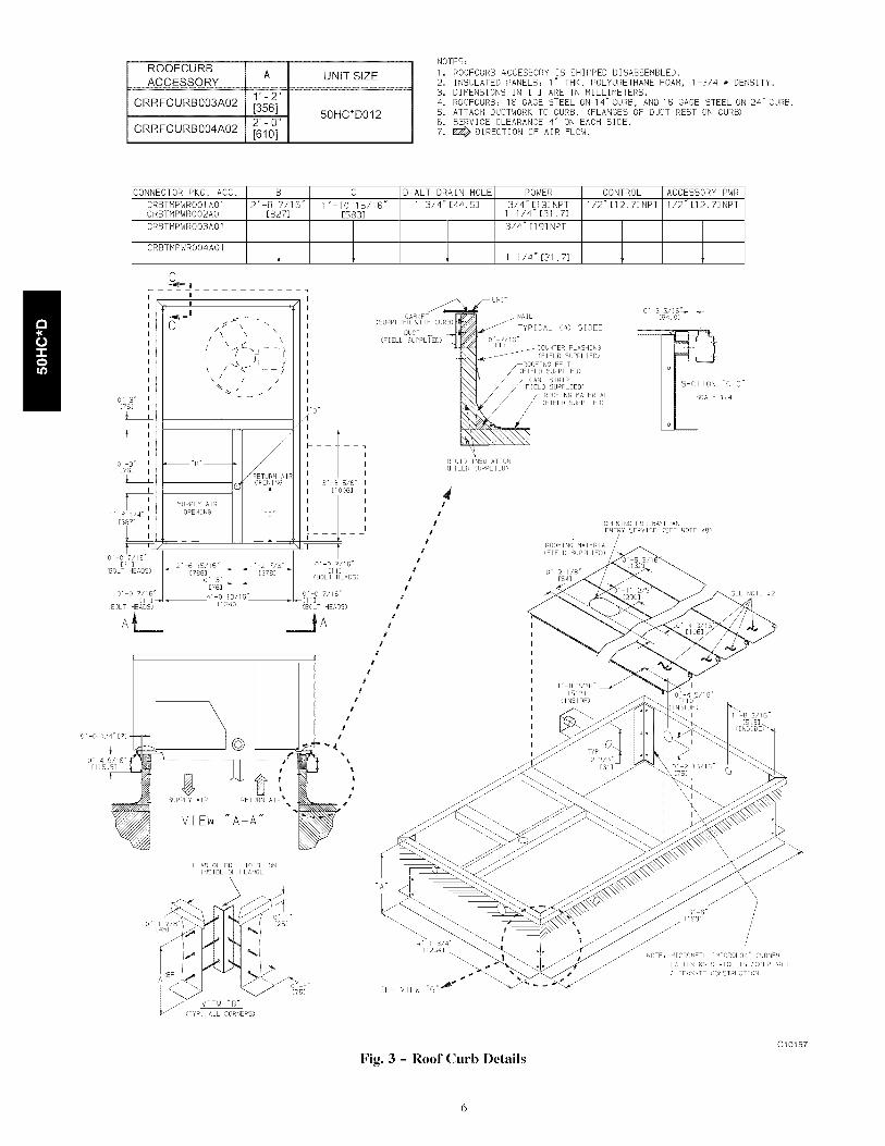
A UNIT SIZEROOFCURBACCESSORY
CRRFCURBOO3A02
CRRFCURBOO4A02
1 ' - 2"
[356]2'-0"[610]
50HC*D012
NOTES=
1. ROOFCURB ACCESSORY IS SHIPPED DISASSEMBLED.2. INSULATED PANELS= 1" THK. POLYURETHANE FOAM, 1-3/4 # DENSITY.3. DIMENSIONS IN ] ARE IN MILLIMETERS.4. ROOFCURB= 18 GAGE STEEL ON 14" CURB, AND 16 GAGE STEEL ON 24" CURB.S. ATTACH DUCTWORK TO CURS. (FLANGES OF DUCT REST ON CURB)S. SERVICE CLEARANCE 4" ON EACH SIDE.
7. E_D[RECT[ON OF AIR FLOW.
CONNECTOR PKG. ACC.
CRBTMPWROO1A01CRBTMPWROO2A01
CRBTMPWROO3A01
CRBTHPWROO4AO1
B
2"-8 7/15"[827]
C
1'-10 15/16"[583]
o' 3"[76]
o' 3 _[75]
/" 3 1/4"[387]
o' o 7//B"Ell]
(80LT HEADS}
O" O 7/15"E11]_
(BOLT HEADS}
C!
i
-,qll : |
/
ii N _ SC \S _ \1\
/ "_m ,h_ _ j)/ / /
%x/ /
J RETURB AIR
{_ OPENING
" 6 ]B/18q[78B]O"
[76]
4' O 13/16 _[/240]
I_D _
,4
ii------ -- I
I
I
I 3" 3 5/8 _ I
I [1006] I
' J 'I
I
I
i ......
o' o 7/16"[11]
(BOLT HEADS}
o' o 7/1B _
(BOLT HEADS}
o" o //4"[?]
HEAD OF BOLT TO BE ONINSIDE OF FLANGE
o' [18"_/8"
D ALT DRAIN HOLE
1 3/4"[44.S]
RIGID INSULATION
(FIELD SUPPLIED)
4#
#
#
#
#
!
#
!
#
##
#
!
!
!
POWER
3/4" [19] NPT1 1/4" [31.7]
3/4" [19] NPT
1 1/4"[31.7]
NAIL
_TYP[CAL (4) SIDES
O'_16"./COUNTER FLASHING
...... "'_" (FIELD SUPPLIED}
ROBF]NG FELT'/(FIELD SUPPLIED)
CONTROL
1/2"[12.7]NPT
ACCESSORY PWR
1/2"[12.7]NPT
1=4
OPENING FOR BASEPAN
ENTRY SERVICE (SEE NOTE #8)
ROOFING MATERIAL
(FIELD
3' 415/16 ,
2 3/8 _
J I
I
I
I
" VIEW "B"(TYP. ALL CORNERS}
O' 2 1/8 _[54]
1" 8 3/!B _
[513]
([NS]DE)
SEE NOTE #2
EVB]
[12B4]
SEE V[EW "B "_
NDTE= [ [CiObIETL "Iq[CROLOK" CORNER
FASTENING DE/ICE IS ACCEPTABLE
ALTERNATE CONSTRUCTION,
Fig. 3 = Roof Curb DetailsC10157
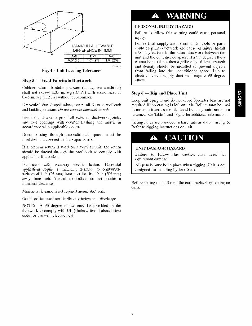
¢
UM ALLOWABLE
'_ _ DIFFERENCE IN. (MM)B A-B ! B-C I A-C
0.5" (13) ! 1.0" (25) J 1.0" (25)
C06110
Fig. 4 - Unit Leveling Tolerances
Step 5 -- Field Fabricate Ductwork
Cabinet return-air static pressure (a negative condition)shall not exceed 0.35 in. wg (87 Pa) with economizer or
0.45 in. wg (112 Pa) without economizer.
For vertical ducted applications, secure all ducts to roof curband buikting structure. Do not connect ductwork to unit.
Insulate and weatherproof all external ductwork, joints,
and roof openings with counter flashing and mastic inaccordance with applicable codes.
Ducts passing through unconditioned spaces must be
insulated and covered with a vapor barrier.
If a plenum return is used on a vertical unit, the return
should be ducted through the roof deck to comply withapplicable fire codes.
For units with accessory electric heaters: Horizontalapplications require a minimum clearance to combustiblesurfaces of 1-in (25 mm) from duct for first 12-in (305 mm)away from unit. Vertical applications do not require aminimum clearance.
Minimum clearance is not required around ductwork.
Outlet grilles must not lie directly below unit discharge.
NOTE: A 90-degree elbow must be provided in the
ductwork to comply with UL (Underwriters Laboratories)code for use with electric heat.
PERSONAL INJURY HAZARD
Failure to follow this warning could cause personalinjury.
For vertical supply and return units, tools or partscould drop into ductwork and cause an injury. Installa 90-degree turn in the return ductwork between theunit and the conditioned space. If a 90-degree elbowcannot be installed, then a grille of sufficient strengthand density should be installed to prevent objectsfrom falling into the conditioned space. Due toelectric heater, supply duct will require 90-degreeelbow.
Step 6 -- Rig and Place Unit
Keep unit upright and do not drop. Spreader bars are not
required if top crating is left on unit. Rollers may be usedto move unit across a roof. Level by using unit frame as a
reference. See Table 1 and Fig. 5 for additional information.
Lifting holes are provided in base rails as shown in Fig. 5.Refer to rigging instructions on unit.
UNIT DAMAGE HAZARD
Failure to follow this caution may result inequipment damage.
All panels must be in place when rigging. Unit is notdesigned for handling by fork truck.
Before setting the unit onto the curb, recheck gasketing oncurb.
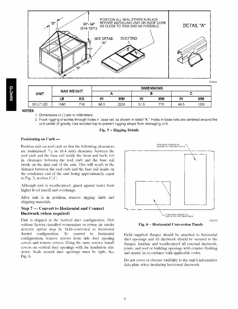
36"- 54"
(914-1371)
POSITION ALL SEAL STRIPS IN PLACEBEFORE INSTALLING UNIT ON ROOF CURBAS CLOSE TO THIS END AS POSSIBLE.
\
SEE DETAIL DUCT END \
"A"
DETAIL "A"
C06005
UNIT
551J*12D
MIAX WEIGHT
LB KG
1580 718
DIMIENSIONS
A B
IN IVllVl IN IVllVl
88.0 2235 31.5 775
C
IN IVllVl
49.5 1255
NOTES:
1. Dimensions in ( ) are in millimeters.
2. Hook rigging shackles through holes in base rail, as shown in detail "A." Holes in base rails are centered around theunit center of gravity. Use wooden top to prevent rigging straps from damaging unit.
Fig. 5 - Rigging Details
Positioning on Curb --
Position unit on roof curb so that the following clearances
are maintained: 1/4 in. (6.4 mm) clearance between theroof curb and the base rail inside the front and back, 0.0in. clearance between the roof curb and the base rail
inside on the duct end of the unit. This will result in the
distance between the roof curb and the base rail inside on
the condenser end of the unit being approximately equal
to Fig. 3, section C-C.
Although unit is weatherproof, guard against water fromhigher level runoff and overhangs.
After unit is in position, remove rigging skids andshipping materials.
Step 7 -- Convert to Horizontal and Connect
Ductwork (when required)
Unit is shipped in the vertical duct configuration. Unitwithout factory-installed economizer or return air smokedetector option may be field-converted to horizontalducted configuration. To convert to horizontalconfiguration, remove screws from side duct openingcovers and remove covers. Using the same screws, installcovers on vertical duct openings with the insulation-sidedown. Seals around duct openings must be tight. SeeFig. 6.
REMOVABLE HORIZONTAL
RETURN DUCT OPENING COVER
\
\\
\\ \'
_ REMOVABLE HORIZONTAL
SUPPLY DUCT OPENING COVER
C06108
Fig. 6 - Horizontal Conversion Panels
Field-supplied flanges should be attached to horizontalduct openings and all ductwork should be secured to the
flanges. Insulate and weatherproof all external ductwork,joints, and roof or building openings with counter flashing
and mastic in accordance with applicable codes.
Do not cover or obscure visibility to the unit's informativedata plate when insulating horizontal ductwork.
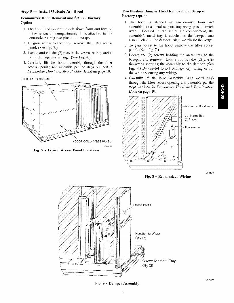
Step 8 1 Install Outside Air Hood
Economizer Hood Removal and Setup - FactoryOption
1. The hood is shipped in knock-down form and locatedin the return air compartment. It is attached to the
economizer using two plastic tie-wraps.
2. To gain access to the hood, remove the filter accesspanel. (See Fig. 7.)
3. Locate and cut the (2) plastic tie-wraps, being careful
to not damage any wiring. (See Fig. 8.)
4. Carefully lift the hood assembly through the filteraccess opening and assemble per the steps outlined in
Economizer Hood and Two--Position Hood on page 10.
FILTER ACCESS PANEL\
Two Position Damper Hood Removal and Setup -Factory Option
1. The hood is shipped in knock-down form and
assembled to a metal support tray using plastic stretchwrap. Located in the return air compartment, the
assembly's metal tray is attached to the basepan andalso attached to the damper using two plastic tie-wraps.
2. To gain access to the hood, remove the filter access
panel. (See Fig. 7.)
3. Locate the (2) screws holding the metal tray to thebasepan and remove. Locate and cut the (2) plastic
tie-wraps securing the assembly to the damper. (See
Fig. 9.) Be careful to not damage any wiring or cuttie-wraps securing any wiring.
4. Carefully lift the hood assembly (with metal tray) 1through the filter access opening and assemble per the
/
steps outlined in Economizer Hood and Two-Position
Hood on page 10.
parts
Cut Plastic Ties
(2) Places
INDOOR COIL ACCESS PANEL
C10146
Fig. 7 - Typical Access Panel Locations
Fig. 8 - Economizer WiringC08633
..Hood Parts
Plastic Tie Wrap
Qty (2)
Fig. 9 - Damper AssemblyC08639
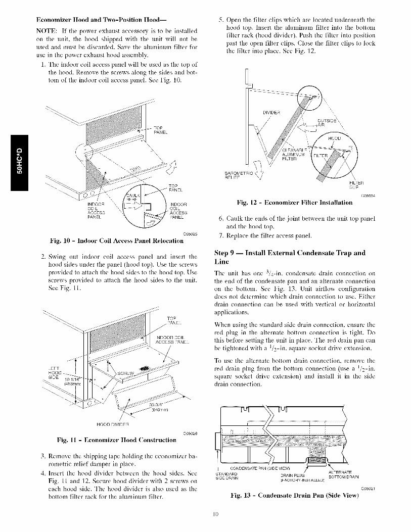
Economizer Hood and Two-Position Hood--
NOTE: If the power exhaust accessory is to be installed
on the unit, the hood shipped with the unit will not beused and must be discarded. Save the aluminum filter for
use in the power exhaust hood assembly.
1. The indoor coil access panel will be used as the top of
the hood. Remove the screws along the sides and bot-tom of the indoor coil access panel. See Fig. 10.
5. Open the filter clips which are located underneath thehood top. Insert the aluminum filter into the bottomfilter rack (hood divider). Push the filter into positionpast the open filter clips. Close the filter clips to lockthe filter into place. See Fig. 12.
TOPPANEL
\\\
4\\\N
TOPPANEL
INDOOR N INDOORCOIL ", COILACCESSPANEL PANEL
C06025
Fig. 10 - Indoor Coil Access Panel Relocation
2. Swing out indoor coil access panel and insert thehood sides under the panel (hood top). Use the screwsprovided to attach the hood sides to the hood top. Usescrews provided to attach the hood sides to the unit.See Fig. 11.
TOPPANEL
INDOOR COILACCESS PANEL
LEFT
SIDE
ALUMINUMFILTER
BAROMETRICRELIEF
FILTERCLIP
C08634
Fig. 12 - Economizer Filter Installation
6. Caulk the ends of the ,joint between the unit top paneland the hood top.
7. Replace the filter access panel.
Step 9 -- Install External Condensate Trap andLine
The unit has one 3/4-in. condensate drain connection onthe end of the condensate pan and an alternate connectionon the bottom. See Fig. 13. Unit airflow configurationdoes not determine which drain connection to use. Eitherdrain connection can be used with vertical or horizontal
applications.
When using the standard side drain connection, ensure thered plug in the alternate bottom connection is tight. Dothis before setting the unit in place. The red drain pan canbe tightened with a 1/2-in. square socket drive extension.
To use the alternate bottom drain connection, remove the
red drain plug from the bottom connection (use a 1/2-in.
square socket drive extension) and install it in the sidedrain connection.
HOOD DIVIDER
C06026
Fig. 11 - Economizer Hood Construction
3. Remove the shipping tape holding the economizer ba-
rometric relief damper in place.
4. Insert the hood divider between the hood sides. See
Fig. 11 and 12. Secure hood divider with 2 screws oneach hood side. The hood divider is also used as thebottom filter rack for the aluminum filter.
ALTERNATESTANDARD DRAIN PLUGSIDE DRAIN BOTTOM DRAIN
(FACTORY-INSTALLED)
Fig. 13 - Condensate Drain Pan (Side View)C08021
10
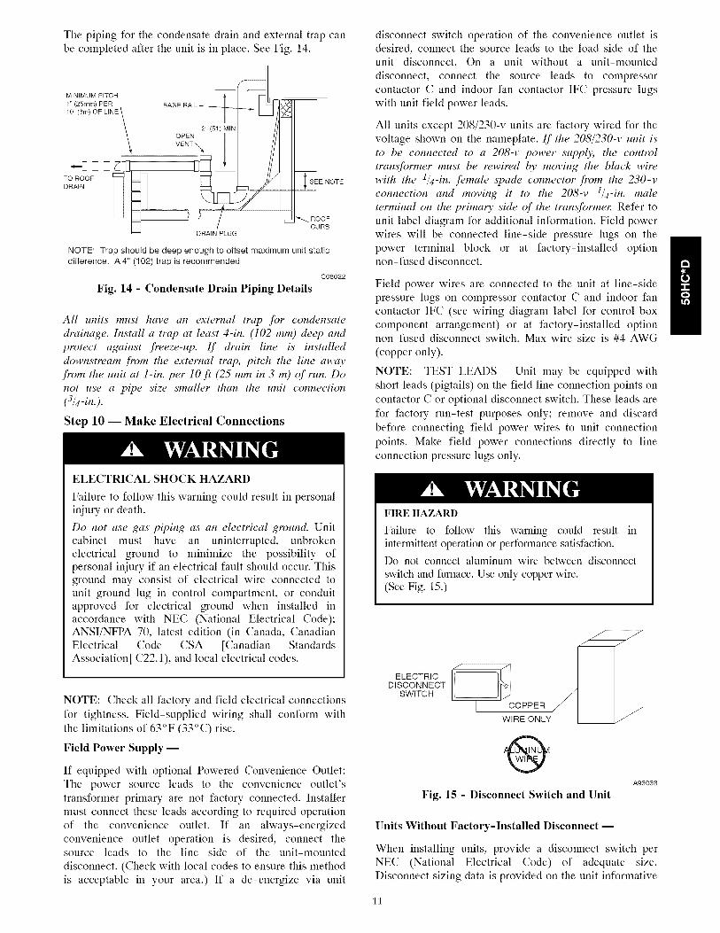
The piping for the condensate drain and external trap canbe completed after the unit is in place. See Fig. 14.
MINIMUM PITCH
!" (25mm) PER -- BASE
10' (3rn) OF LINE_ 2" (51) MIN
\ OPEN
VENT N,._
I SEE NOTETODRAIN ,f
_'--. ROOF
CURB
DRAIN PLUG
NOTE: Trap should be deep enough to offset maximum unit static
difference. A4" (102)trap is recommended
C08022
Fig. 14 - Condensate Drain Piping Details
All units" must have an external trap for condensate
drainage. Install a trap at least 4-in. (102 mm) deep andprotect against freeze-up. If drain line is installed
downstream from the external trap, pitch the line awayfrom the unit at 1-in. per 10 f! (25 mm in 3 in) of run. Do
not use a pipe size smaller than the unit connection(-%-in.).
Step 10 -- Make Electrical Connections
ELECTRICAL SHOCK HAZARD
Failure to follow this warning could result in personalinjury or death.
Do not use gas piping as an electrical ground. Unit
cabinet must have an uninterrupted, unbrokenelectrical ground to minimize the possibility ofpersonal injury if an electrical fault should occur. Thisground may consist of electrical wire connected tounit ground lug in control compartment, or conduitapproved for electrical ground when installed inaccordance with NEC (National Electrical Code);ANSI/NFPA 70, latest edition (in Canada, Canadian
Electrical Code CSA [Canadian StandardsAssociation] C22.1), and local electrical codes.
NOTE: Check all factory and field electrical connections
for tightness. Field-supplied wiring shall conform with
the limitations of 63 °F (33 ° C) rise.
Field Power Supply --
If equipped with optional Powered Convenience Outlet:The power source leads to the convenience outlet's
transformer primary are not factory connected. Installer
must connect these leads according to required operationof the convenience outlet. If an always-energized
convenience outlet operation is desired, connect thesource leads to the line side of the unit-mounted
disconnect. (Check with local codes to ensure this methodis acceptable in your area.) If a de-energize via unit
disconnect switch operation of the convenience outlet isdesired, connect the source leads to the load side of theunit disconnect. On a unit without a unit-mounted
disconnect, connect the source leads to compressor
contactor C and indoor fan contactor IFC pressure lugswith unit field power leads.
All units except 208/230-v units are factory wired for the
voltage shown on the nameplate. If the 208/230-v unit isto be connected to a 208-v power suppl); the control
transformer must be rewired by moving the black wirewith the 1/4-in. female spade connector from the 230-vconnection and moving it to the 208-v 1/4-in. male
terminal on the primary side of the transformen Refer to
unit label diagram for additional information. Field power
wires will be connected line-side pressure lugs on thepower terminal block or at factory-installed optionnon-fused disconnect.
Field power wires are connected to the unit at line-sidepressure lugs on compressor contactor C and indoor fan
contactor IFC (see wiring diagram label for control boxcomponent arrangement) or at factory-installed optionnon-fused disconnect switch. Max wire size is #4 AWG
(copper only).
NOTE: TEST LEADS - Unit may be equipped with
short leads (pigtails) on the field line connection points on
contactor C or optional disconnect switch. These leads are
for factory run-test purposes only; remove and discard
before connecting field power wires to unit connection
points. Make field power connections directly to lineconnection pressure lugs only.
FIRE HAZARD
Failure to follow this warning could result inintermittent operation or performance satisfaction.
Do not connect aluminum wire between disconnect
switch and furnace. Use only copper wire.(See Fig. 15.)
ELECTRIC _]_DISCONNECT
SWITCH
[ COPPER
WIRE ONLY
QFig. 15 - Disconnect Switch and Unit
A93033
Units Without Factory-Installed Disconnect --
When installing units, provide a disconnect switch per
NEC (National Electrical Code) of adequate size.Disconnect sizing data is provided on the unit informative
11
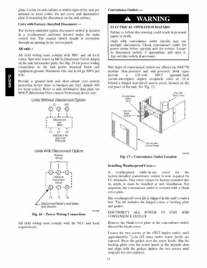
plate. Locate on unit cabinet or within sight of the unit pernational or local codes. Do not cover unit informative
plate if mounting the disconnect on the unit cabinet.
Units with Factory-Installed Disconnect --
The factory-installed option disconnect switch is locatedin a weatherproof enclosure located under the maincontrol box. The manual switch handle is accessible
through an opening in the access panel.
All units -
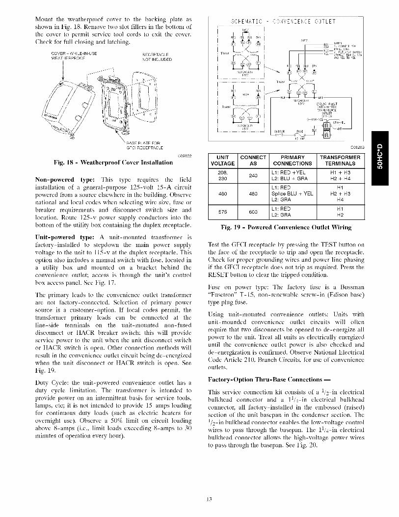
All field wiring must comply with NEC and all localcodes. Size wire based on MCA (Minimum Circuit Amps)on the unit informative plate. See Fig. 16 for power wiringconnections to the unit power terminal block andequipment ground. Maximum wire size is #4 ga AWG perpole.
Provide a ground-fault and short-circuit over-currentprotection device (fuse or breaker) per NEC Article 440(or local codes). Refer to unit informative data plate forMOCP (Maximum Over-current Protection) device size.
Units Without Disconnect OptionC IFC
OO#| | |
J I -L=| |i Disconnect iI per Ii NEC i
_=r--T--_-_L1 L2 L3
208/230-3 -60460-3 -60575-3 -60
Units With Disconnect OptionFactoryWiring
I I I;I Optional iI Disconnect iI Switch iI I
and discard.
Fig. 16 - Power Wiring ConnectionsC09349
All field wiring must comply with the NEC and localrequirements.
Convenience Outlets-
ELECTRICAL OPERATION HAZARD
Failure to follow this warning could result in personalinjury or death.
Units with convenience outlet circuits may usemultiple disconnects. Check convenience outlet forpower status before opening unit for service. Locateits disconnect switch, if appropriate, and open it.Tag-out this switch, if necessary.
Two types of convenience outlets are offered on 50HC*Dmodels: Non-powered and unit-powered. Both typesprovide a 125-volt GFCI (ground-faultcircuit-interrupter) duplex receptacle rated at 15-Abehind a hinged waterproof access cover, located on theend panel of the unit. See Fig. 17.
Pwd -CO
Convenience Transformer
Outlet SGFCI
Pwd-CO
C08128
Fig. 17 - Convenience Outlet Location
Installing Weatherproof Cover -
A weatherproof while-in-use cover for thefactory-installed convenience outlets is now required by
UL standards. This cover cannot be factory-mounted due
its depth; it must be installed at unit installation. Forshipment, the convenience outlet is covered with a blank
cover plate.
The weatherproof cover kit is shipped in the unit's control
box. The kit includes the hinged cover, a backing plate
and gasket.
DISCONNECT ALL POWER TO UNIT ANDCONVENIENCE OUTLET.
Remove the blank cover plate at the convenience outlet;discard the blank cover.
Loosen the two screws at the GFCI duplex outlet, untilapproximately 1/2-in (13 mm) under screw heads are
exposed. Press the gasket over the screw heads. Slip the
backing plate over the screw heads at the keyhole slotsand align with the gasket; tighten the two screws until
snug (do not over-tighten).
12
Mount the weatherproof cover to the backing plate asshown in Fig. 18. Remove two slot fillers in the bottom of
the cover to permit service tool cords to exit the cover.Check for full closing and latching.
COVER WHILE-IN=USE RECEPTACLE
WEATHERPROOF NOT INCLUDED
BASE PLATE FORGFCI RECEPTACLE
Fig. 18 - Weatherproof Cover InstallationC09022
Non-powered type: This type requires the field
installation of a general-purpose 125-volt 15-A circuitpowered from a source elsewhere in the building. Observe
national and local codes when selecting wire size, fuse orbreaker requirements and disconnect switch size and
location. Route 125-v power supply conductors into the
bottom of the utility box containing the duplex receptacle.
Unit-powered type: A unit-mounted transformer is
factory-installed to stepdown the main power supply
voltage to the unit to l15-v at the duplex receptacle. Thisoption also includes a manual switch with fuse, located in
a utility box and mounted on a bracket behind theconvenience outlet; access is through the unit's control
box access panel. See Fig. 17.
The primary leads to the convenience outlet transformerare not factory-connected. Selection of primary power
source is a customer-option. If local codes permit, thetransformer primary leads can be connected at theline-side terminals on the unit-mounted non-fused
disconnect or HACR breaker switch; this will provideservice power to the unit when the unit disconnect switch
or HACR switch is open. Other connection methods willresult in the convenience outlet circuit being de-energized
when the unit disconnect or HACR switch is open. SeeFig. 19.
Duty Cycle: the unit-powered convenience outlet has a
duty cycle limitation. The transformer is intended toprovide power on an intermittent basis for service tools,
lamps, etc; it is not intended to provide 15-amps loadingfor continuous duty loads (such as electric heaters for
overnight use). Observe a 50% limit on circuit loading
above 8-amps (i.e., limit loads exceeding 8-amps to 30minutes of operation every hour).
SCHEMATIC - CONVENTENCE OUTLET
460V
YE LUOL
SECONDARY
1Roy
JD JA
TRAN4 _,_ _ 603V t
SECO2¢Y
D4ov, NOTES:
6kU--1 CONNECTPER
6RA--R LOCAL CODE
yED--2 FOR 240V SUPPLYEL--CONNECT 8LU TO GRAAND RED TO YEL
TRAN4
C08283
UNIT CONNECT PRIMARY TRANSFORMERVOLTAGE AS CONNECTIONS TERMINALS
208, LI: RED +YEL H1 + H3240280 L2: BLU + GRA H2 + H4
L1: RED H1460 480 Splice BLU + YEL H2 + H3
L2: GRA H4
L1: RED H1575 600 L2: GRA H2
Fig. 19 - Powered Convenience Outlet Wiring
Test the GFCI receptacle by pressing the TEST button onthe face of the receptacle to trip and open the receptacle.
Check for proper grounding wires and power line phasingif the GFCI receptacle does not trip as required. Press the
RESET button to clear the tripped condition.
Fuse on power type: The factory fuse is a Bussman"Fusetron" T-15, non-renewable screw-in (Edison base)
type plug fuse.
Using unit-mounted convenience outlets: Units withunit-mounded convenience outlet circuits will often
require that two disconnects be opened to de-energize allpower to the unit. Treat all units as electrically energized
until the convenience outlet power is also checked and
de-energization is confirmed. Observe National ElectricalCode Article 210, Branch Circuits, for use of convenienceoutlets.
Factory- Option Thru-Base Connections --
This service connection kit consists of a 1/2-in electricalbulkhead connector and a ll/4-in electrical bulkhead
connector, all factory-installed in the embossed (raised)section of the unit basepan in the condenser section. The1/2-in bulkhead connector enables the low-voltage control
wires to pass through the basepan. The ll/4-in electrical
bulkhead connector allows the high-voltage power wires
to pass through the basepan. See Fig. 20.
13
LOW VOLTAGE
CONNECTOR
HIGH VOLTAGECONDUITCONNECTOR
C08637
Fig. 20 - Thru-Base Connection Fittings
Check tightness of connector lock nuts before connectingelectrical conduits.
Field-supplied and field-installed liquidtight conduitconnectors and conduit may be attached to the connectorson the basepan. Pull correctly rated high voltage and lowvoltage through appropriate conduits. Connect the powerconduit to the internal disconnect (if unit is so equipped)or to the external disconnect (through unit side panel). Ahole must be field cut in the main control box bottom onthe left side so the 24-v control connections can be made.
Connect the control power conduit to the unit control boxat this hole.
Units without Thru-Base Connections --
1. Install power wiring conduit through side panel open-ings. Install conduit between disconnect and controlbox.
2. Install power lines to terminal connections as shownin Fig. 16.
All Units --
Voltage to compressor terminals during operation must bewithin voltage range indicated on unit nameplate. See
Table 10. On 3-phase units, voltages between phases mustbe balanced within 2% and the current within 10%. Use
the formula shown in the legend for Table 10, Note 2 (see
page 38) to determine the percent of voltage imbalance.Operation on improper line voltage or excessive phase
imbalance constitutes abuse and may cause damage toelectrical components. Such operation would invalidate
any applicable Carrier warranty.
Field Control Wiring --
The 50HC*D unit requires an external temperature control
device. This device can be a thermostat (field-supplied)or a PremierLink controller (available as factory-installed
option or as field-installed accessory, for use on a CarrierComfort Network or as a stand alone control) or the
RTU-MP Controller for Building Management Systems
using non-CCN protocols (RTU-MP is available as afactory-installed option only).
Thermostat --
Install a Carrier-approved accessory thermostat accordingto installation instructions included with the accessory.
For complete economizer function, select a two-stagecooling thermostat. Locate the thermostat accessory on a
solid wall in the conditioned space to sense average
temperature in accordance with the thermostat installationinstructions.
If the thermostat contains a logic circuit requiring 24-vpower, use a thermostat cable or equivalent single leads ofdifferent colors with minimum of seven leads. If the
thermostat does not require a 24-v source (no "C"connection required), use a thermostat cable or equivalentwith minimum of six leads. Check the thermostat
installation instructions for additional features which
might require additional conductors in the cable.
For wire runs up to 50 ft. (15 m), use no. 18 AWG(American Wire Gage) insulated wire (35°C minimum).For 50 to 75 ft. (15 to 23 m), use no. 16 AWG insulatedwire (35°C minimum). For over 75 ft. (23 m), use no. 14AWG insulated wire (35°C minimum). All wire sizeslarger than no. 18 AWG cannot be directly connected tothe thermostat and will require a junction box and spliceat the thermostat.
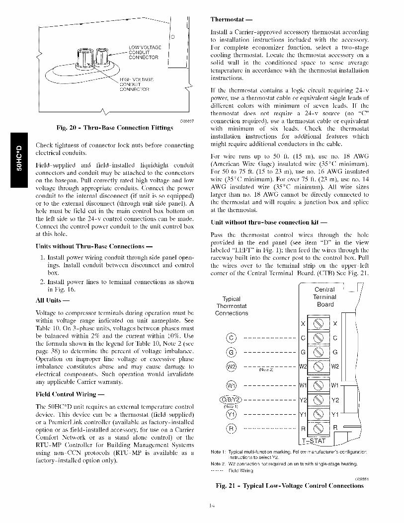
Unit without thru-base connection kit --
Pass the thermostat control wires through the holeprovided in the end panel (see item "D" in the view
labeled "LEFT" in Fig. 1); then feed the wires through theraceway built into the corner post to the control box. Pull
the wires over to the terminal strip on the upper-left
corner of the Central Terminal Board. (CTB) See Fig. 21.
TypicalThermostatConnections
©
G
(Note I)
©®
>(
_J
3
(Note 2) q2
Wl
Y2
Y1
Central l J7Terminal
Board
@ w2
__@ ,(2@ vl
R @ R
Note 1: Typical multbfunction marking. Follow manufacturer's configurationinstructions to select Y2.
Note 2:W2 connection not required on units with single-stage heating.
= = = Field Wiring
C09351
Fig. 21 - Typical Low-Voltage Control Connections
14
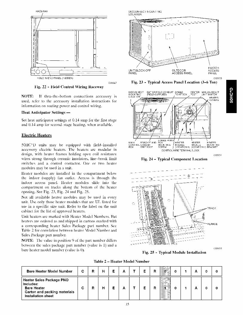
RACEWAY DISCONNECT MOUNTINGLOCATION
HOLE IN END PANEL (HIDDEN)
C08027
Fig. 22 - Field Control Wiring Raceway
NOTE: If thru-the-bottom connections accessory is
used, refer to the accessory installation instructions for
information on routing power and control wiring.
Heat Anticipator Settings i
Set heat anticipator settings at 0.14 amp for the first stage
and 0.14 amp for second-stage heating, when available.
Electric Heaters
50HC*D units may be equipped with field-installedaccessory electric heaters. The heaters are modular indesign, with heater frames holding open coil resistancewires strung through ceramic insulators, line-break limitswitches and a control contactor. One or two heater
modules may be used in a unit.
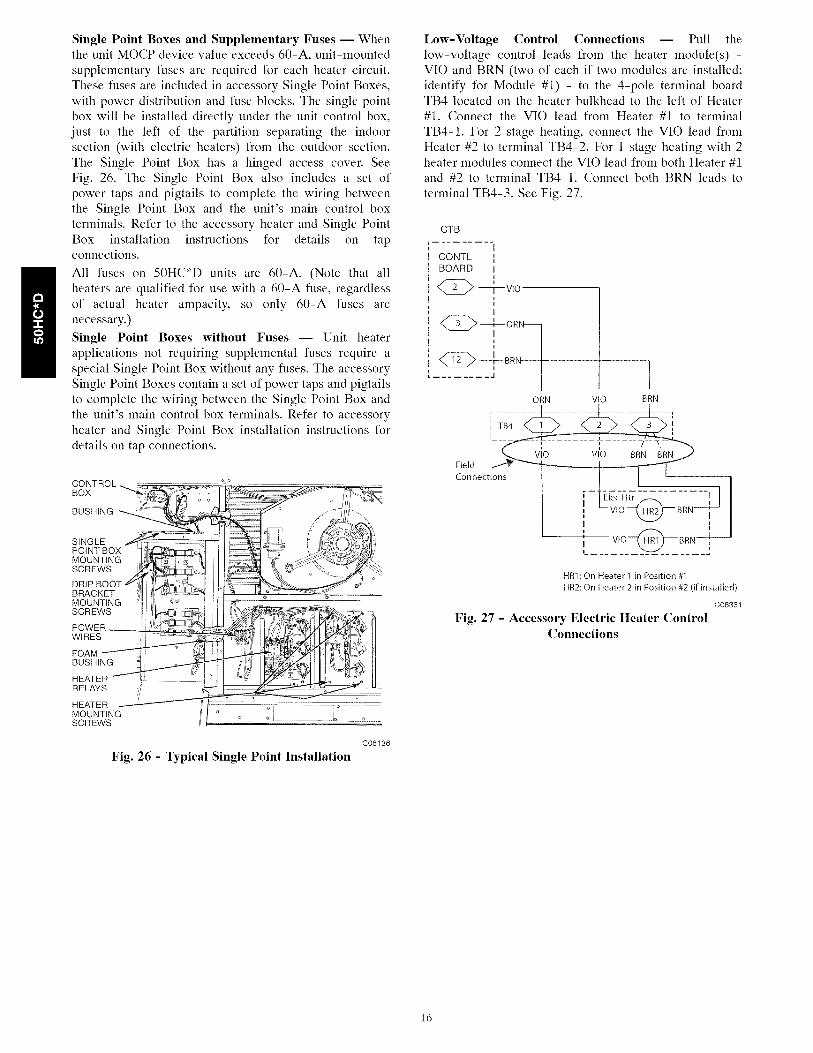
Heater modules are installed in the compartment belowthe indoor (supply) fan outlet. Access is through theindoor access panel. Heater modules slide into thecompartment on tracks along the bottom of the heateropening. See Fig. 23, Fig. 24 and Fig. 25.
Not all available heater modules may be used in everyunit. Use only those heater modules that are UL listed foruse in a specific size unit. Refer to the label on the unitcabinet for the list of approved heaters.Unit heaters are marked with Heater Model Numbers. But
heaters are ordered as and shipped in cartons marked witha corresponding heater Sales Package part number. SeeTable 2 for correlation between heater Model Number and
Sales Package part number.
NOTE: The value in position 9 of the part number differsbetween the sales package part number (value is 1) and abare heater model number (value is 0).
UNIT BLOCK-OFFPANEL
INDOOROUTDOOR ACCESSACCESS PANEL PANEL
C08133
Fig. 23 - Typical Access Panel Location (3-6 Ton)
DISCONNECT EMT OR RIGID CONDUIT SINGLE CENTER MANUAL RESET
MOUNTING (FIELD-SUPPLIED) POINT BOX POST LIMIT SWITCH
MAIN BRACKET AND BOX HEATER HEATER HEATER
CONTROL CONDUIT MOUNTING MODULE MODULE MOUNTING
BOX DRIP BOOT SCREW (LOCATION 1) (LOCATION 2) BRACKET
CONTROLWIRE TERMINAL BLOCK
C08134
Fig. 24 - Typical Component Location
Fig. 25 - Typical Module InstallationC08135
Table 2 - Heater Model Number
Bare Heater Model Number
Heater Sales Package PNOIncludes:
Bare Heater
Carton and packing materialsInstallation sheet
15
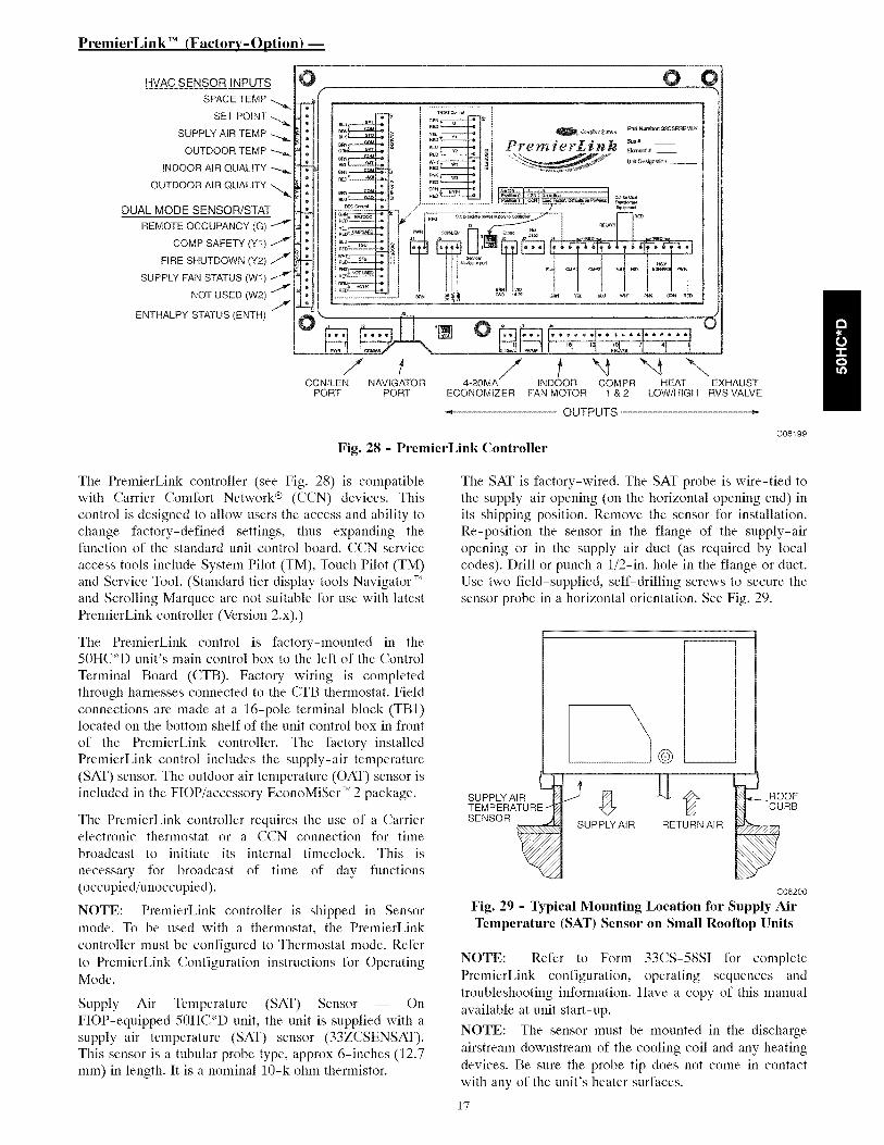
Single Point Boxes and Supplementary Fuses -- Whenthe unit MOCP device value exceeds 60-A, unit-mounted
supplementary fuses are required for each heater circuit.These fuses are included in accessory Single Point Boxes,with power distribution and fuse blocks. The single pointbox will be installed directly under the unit control box,just to the left of the partition separating the indoorsection (with electric heaters) from the outdoor section.The Single Point Box has a hinged access cover. SeeFig. 26. The Single Point Box also includes a set ofpower taps and pigtails to complete the wiring betweenthe Single Point Box and the unit's main control boxterminals. Refer to the accessory heater and Single PointBox installation instructions for details on tapconnections.
All fuses on 50HC*D units are 60-A. (Note that allheaters are qualified for use with a 60-A fuse, regardlessof actual heater ampacity, so only 60-A fuses arenecessary.)
Single Point Boxes without Fuses -- Unit heaterapplications not requiring supplemental fuses require aspecial Single Point Box without any fuses. The accessorySingle Point Boxes contain a set of power taps and pigtailsto complete the wiring between the Single Point Box andthe unit's main control box terminals. Refer to accessoryheater and Single Point Box installation instructions fordetails on tap connections.
CONTROLBOX
BUSHING
SINGLEPOINTMOUNTINGSCREWS
DRIP B(BRACKETMOUNTINGSCREWS
WIRES
FOAMBUSHING
HEATERRELAYS
HEATERMOUNTINGSCREWS
Fig. 26 - Typical Single Point InstallationC08136
Low-Voltage Control Connections -- Pull the
low-voltage control leads from the heater module(s) -
VIO and BRN (two of each if two modules are installed;identify for Module #1) - to the 4-pole terminal boardTB4 located on the heater bulkhead to the left of Heater
#1. Connect the VIO lead from Heater #1 to terminal
TB4-1. For 2 stage heating, connect the VIO lead fromHeater #2 to terminal TB4-2. For 1 stage heating with 2heater modules connect the VIO lead from both Heater #1
and #2 to terminal TB4-1. Connect both BRN leads to
terminal TB4-3. See Fig. 27.
CTB
I
CONTL ',BOARD I
"---l-- V[O
II
@ --l--oa_--I1
__BRNL ........ =1
ORN VlO BRN
',i=............ 4.......... I ........... ,
Field
Connections o--I ..... L ....
i.::j, 7- ,i i
HR1 : On Heater 1 in Position #1
HR2: On Heater 2 in Position #2 (if installed)
C08331
Fig. 27 - Accessory Electric Heater ControlConnections
16
PrcmierLink TM (Factory-Option)-
0 0 ¢.we ........SUPPLYAIRTEMP.... N_I 0=E_ °°..i:gZgl a_.o,,,,_,,.,_......""°'_='_ I
OUTDOORTEMPCNil=_ :::_1, Prem;e_k :,:,-- I8_ M ......
INDOOR A'R QUALITY ---. I-]Q'L ::_ :_ _ u_e_....... I
OUTDOOR AIR QUALITY "-. _:1 S_-_I I
DUAL MODE SENSOPdSTAT I_ -;_-_................................................-, ,. _ _ D ................. _%"%°_ IREMOTE OCCUPANCY (G) -'" t4 _ I _,,_ _ I_°_°_ I ....II I
COMP SAFETY (Y1) J_" L4il IFIRE SHUTDOWN (Y2) /_ :;7_w- i I II t*_22'_ II "[' I / [ ql-._-_-_ I
SUPPLYFANSTATUS(WI,-"'_F451 i I III.........H °I°1"1 / I =1"1I_lJ'l .g_'_" i I IlI _.li_ I I I / i i I I
NOT UbED (W2) I I • I ............................J _ _ _ ...... ,_,,. ............
ENTHALPYSTATUS(ENT,)""€'_0_ 0 _l_..:4..i_:.:l,,_ "
/ _ / t ",4 "-4 "-,,CCNILEN NAVIGATOR 4-20MA INDOOR COMPR HEAT EXHAUSTPORT PORT ECONOMIZER FAN MOTOR I & 2 LOWIHIGH RVS VALVE
OUTPUTS
Fig. 28 - PremierLink ControllerC08199
The PremierLink controller (see Fig. 28) is compatiblewith Carrier Comfort Network ® (CCN) devices. Thiscontrol is designed to allow users the access and ability tochange factory-defined settings, thus expanding thefunction of the standard unit control board. CCN service
access tools include System Pilot (TM), Touch Pilot (TM)and Service Tool. (Standard tier display tools Navigator TM
and Scrolling Marquee are not suitable for use with latestPremierLink controller (Version 2.x).)
The PremierLink control is factory-mounted in the50HC*D unit's main control box to the left of the Control
Terminal Board (CTB). Factory wiring is completedthrough harnesses connected to the CTB thermostat. Fieldconnections are made at a 16-pole terminal block (TB1)located on the bottom shelf of the unit control box in front
of the PremierLink controller. The factory-installedPremierLink control includes the supply-air temperature(SAT) sensor. The outdoor air temperature (OAT) sensor isincluded in the FIOP/accessory EconoMi$er TM 2 package.
The PremierLink controller requires the use of a Carrierelectronic thermostat or a CCN connection for timebroadcast to initiate its internal timeclock. This is
necessary for broadcast of time of day functions(occupied/unoccupied).
NOTE: PremierLink controller is shipped in Sensormode. To be used with a thermostat, the PremierLink
controller must be configured to Thermostat mode. Refer
to PremierLink Configuration instructions for OperatingMode.
Supply Air Temperature (SAT) Sensor -- OnFlOP-equipped 50HC*D unit, the unit is supplied with asupply-air temperature (SAT) sensor (33ZCSENSAT).This sensor is a tubular probe type, approx 6-inches (12.7mm) in length. It is a nominal 10-k ohm thermistor.
The SAT is factory-wired. The SAT probe is wire-tied tothe supply-air opening (on the horizontal opening end) inits shipping position. Remove the sensor for installation.Re-position the sensor in the flange of the supply-airopening or in the supply air duct (as required by localcodes). Drill or punch a 1/2-in. hole in the flange or duct.Use two field-supplied, self-drilling screws to secure thesensor probe in a horizontal orientation. See Fig. 29.
\
SENSOR _ SUPPLYAIR
m
RETURN AIR
C08200
Fig. 29 - Typical Mounting Location for Supply AirTemperature (SAT) Sensor on Small Rooftop Units
NOTE: Refer to Form 33CS-58SI for completePremierLink configuration, operating sequences andtroubleshooting information. Have a copy of this manualavailable at unit start-up.
NOTE: The sensor must be mounted in the dischargeairstream downstream of the cooling coil and any heatingdevices. Be sure the probe tip does not come in contactwith any of the unit's heater surfaces.
17
li!ii i ?t _
I!i i i H_o
:>
o
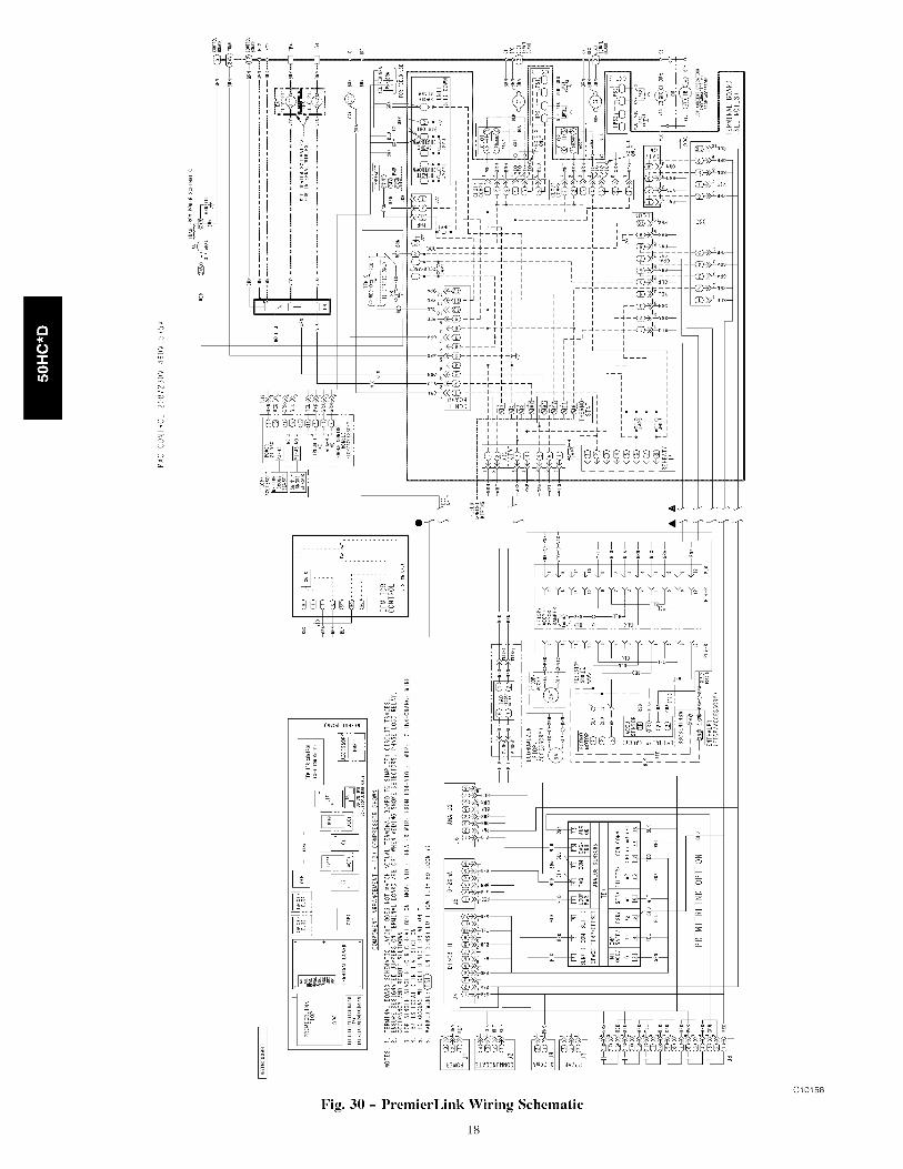
Fig. 30 - PremierLink Wiring Schematic
18
010158
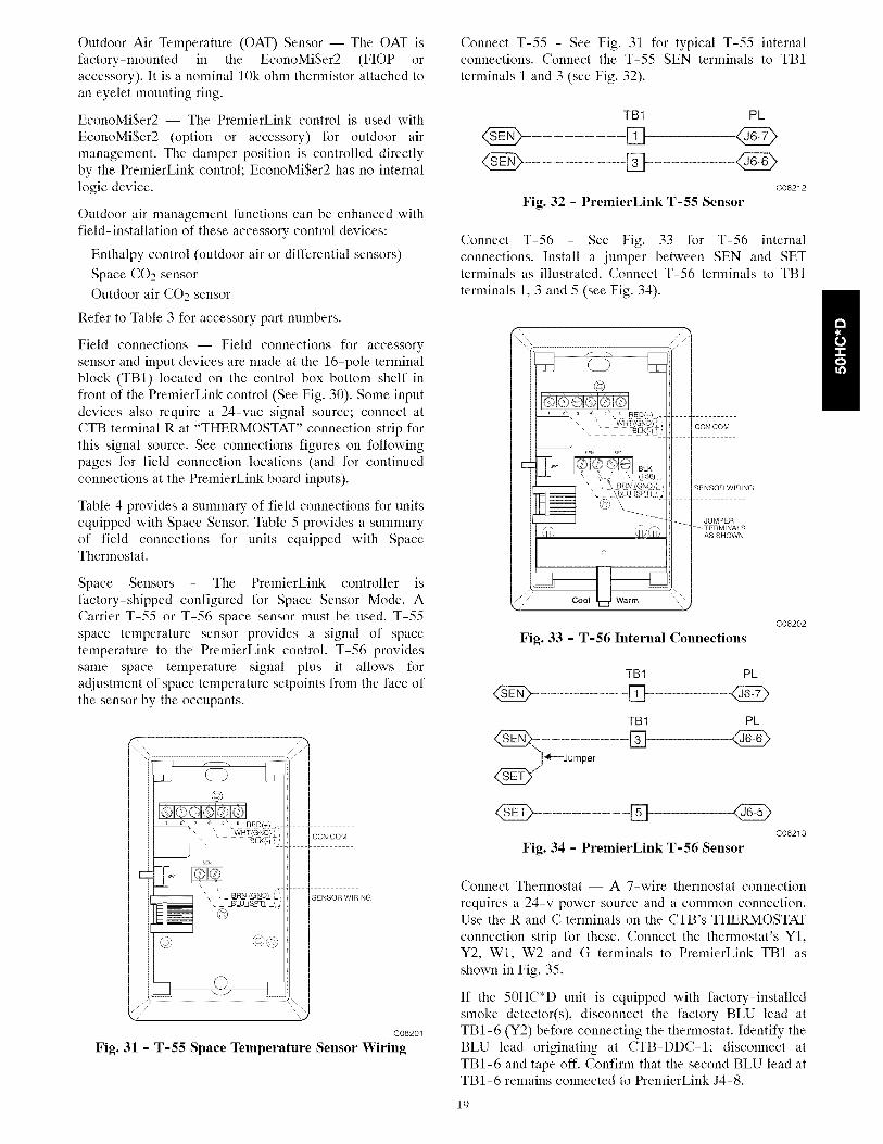
Outdoor Air Temperature (OAT) Sensor I The OAT isfactory-mounted in the EconoMi$er2 (FIOP or
accessory). It is a nominal 10k ohm thermistor attached toan eyelet mounting ring.
EconoMi$er2 I The PremierLink control is used with
EconoMiSer2 (option or accessory) for outdoor airmanagement. The damper position is controlled directlyby the PremierLink control; EconoMi$er2 has no internal
logic device.
Outdoor air management functions can be enhanced with
field-installation of these accessory control devices:
Enthalpy control (outdoor air or differential sensors)
Space CO: sensor
Outdoor air CO: sensor
Refer to Table 3 for accessory part numbers.
Field connections I Field connections for accessorysensor and input devices are made at the 16-pole terminal
block (TB1) located on the control box bottom shelf infront of the PremierLink control (See Fig. 30). Some input
devices also require a 24-vac signal source; connect atCTB terminal R at "THERMOSTAT" connection strip for
this signal source. See connections figures on following
pages for field connection locations (and for continuedconnections at the PremierLink board inputs).
Table 4 provides a summary of field connections for units
equipped with Space Sensor. Table 5 provides a summaryof field connections for units equipped with SpaceThermostat.
Space Sensors - The PremierLink controller isfactory-shipped configured for Space Sensor Mode. A
Carrier T-55 or T-56 space sensor must be used. T-55space temperature sensor provides a signal of space
temperature to the PremierLink control. T-56 providessame space temperature signal plus it allows for
adjustment of space temperature setpoints from the face ofthe sensor by the occupants.
s_
©
_ .\ 5,,_ 0Ep(+)j.
_, _ _W_HL(Q_N_)L',\ BL@) t]
Wl
\ / BRN (GND& [ ',
@
4:b,
©
CCN COM
SENSOR WIRING
C08201
Fig. 31 - T-55 Space Temperature Sensor Wiring
Connect T-55 - See Fig. 31 for typical T-55 internalconnections. Connect the T-55 SEN terminals to TB1
terminals 1 and 3 (see Fig. 32).
TB1 PL
C08212
Fig. 32 - PremierLink T-55 Sensor
Connect T-56 - See Fig. 33 for T-56 internal
connections. Install a jumper between SEN and SETterminals as illustrated. Connect T-56 terminals to TB1
terminals 1, 3 and 5 (see Fig. 34).
©
©
CCN COM
SENSOR WIRING
JUMPERTERM INALSAS SHOWN
Fig. 33 - T-56 Internal Connections
C08202
<NA>
!_l'---Jumper
TB1
DTB1
%
PL
PL
DC08213
Fig. 34 - PremierLink T-56 Sensor
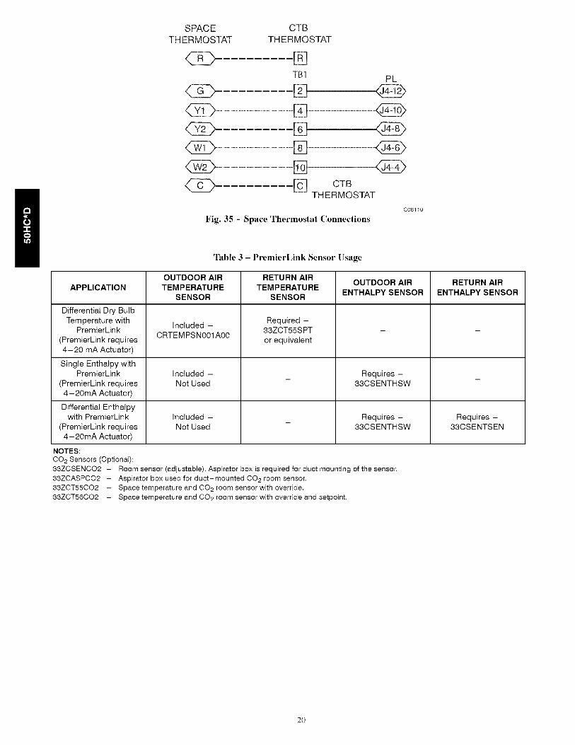
Connect Thermostat I A 7-wire thermostat connection
requires a 24-v power source and a common connection.Use the R and C terminals on the CTB's THERMOSTAT
connection strip for these. Connect the thermostat's Y1,Y2, W1, W2 and G terminals to PremierLink TB1 as
shown in Fig. 35.
If the 50HC*D unit is equipped with factory-installed
smoke detector(s), disconnect the factory BLU lead atTB1-6 (Y2) before connecting the thermostat. Identify the
BLU lead originating at CTB-DDC-1; disconnect atTB1-6 and tape off. Confirm that the second BLU lead atTB1-6 remains connected to PremierLink J4-8.
19
SPACE CTB
TH E R M O STAT TH ER M O STAT
02> %
G2'
PL
D CTBTH ERMOSTAT
C08119
Fig. 35 - Space Thermostat Connections
Table 3 - PremierLink Sensor Usage
OUTDOOR AIR RETURN AIROUTDOOR AIR RETURN AIR
APPLICATION TEMPERATURE TEMPERATUREENTHALPY SENSOR ENTHALPY SENSOR
SENSOR SENSOR
Differential Dry BulbTemperature with
PremierLink
(PremierLink requires4- 20 mA Actuator)
Single Enthalpy withPremierLink
(PremierLink requires4- 20mA Actuator)
Differential Enthalpywith PremierLink
(PremierLink requires4- 20mA Actuator)
Included -CRTEMPSNOO1AO0
Included -Not Used
Included -Not Used
Required -33ZCT55SPT
or equivalent
Requires -33CSENTHSW
Requires -33CSENTHSW
NOTES:
CO 2 Sensors (Optional):33ZCSENC02 - Room sensor (adjustable). Aspirator box is required for duct mounting of the sensor.33ZCASPC02 - Aspirator box used for duct-mounted CO 2 room sensor.33ZCT55C02 - Space temperature and CO2 room sensor with override.33ZCT56C02 - Space temperature and CO2 room sensor with override and setpoint.
Requires -33CSENTSEN
20
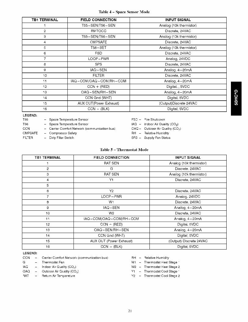
Table 4 - Space Sensor Mode
TB1 TERMINAL
1
2
3
4
5
6
7
8
9
10
11
12
13
14
15
16
LEGEND:T55
T56
CCN
CMPSAFE -
FILTER
FIELD CONNECTION INPUT SIGNAL
T55- SEN/T56- SEN Analog (1Okthermistor)
RMTOCC Discrete, 24VAC
T55- SEN/T56- SEN Analog (1Okthermistor)
CMPSAFE Discrete, 24VAC
T56- SET Analog (1Okthermistor)
FSD Discrete, 24VAC
LOOP- PWR Analog, 24VDC
SPS Discrete, 24VAC
IAQ-SEN Analog, 4-20mA
FILTER Discrete, 24VAC
IAQ- COM/OAQ- COM/RH- COM Analog, 4-20mA
CCN + (RED) Digital,, 5VDC
OAQ-SEN/RH-SEN Analog, 4-20mA
CCN Gnd (WriT) Digital, 5VDC
AUX OUT(Power Exhaust) (Output)Discrete 24VAC
CCN - (BLK) Digital, 5VDC
Space Temperature Sensor
Space Temperature SensorCarrier Comfort Network (communication bus)
Compressor Safety
Dirty Filter Switch
FSD - Fire Shutdown
IAQ - Indoor Air Quality (C02)
OAQ- Outdoor Air Quality (C02)
RH - Relative Humidity
SFS - Supply Fan Status
Table 5 - Thermostat Mode
TB1 TERMINAL FIELD CONNECTION INPUT SIGNAL
1 RAT SEN Analog (10k thermistor)
2 G Discrete, 24VAC
3 RAT SEN Analog (1Ok thermistor)
4 Y1 Discrete, 24VAC
5
6 Y2 Discrete, 24VAC
7 LOOP- PWR Analog, 24VDC
8 Wl Discrete, 24VAC
9 IAQ-SEN Analog, 4-20mA
10 W2 Discrete, 24VAC
11 IAQ- COM/OAQ- COM/RH-COM Analog, 4- 20mA
12 CCN + (RED) Digital, 5VDC
13 OAQ - SEN/RH - SEN Analog, 4- 20mA
14 CCN Gnd (WriT) Digital, 5VDC
15 AUX OUT (Power Exhaust) (Output) Discrete 24VAC
16 CCN - (BLK) Digital, 5VDC
LEGEND:
CCN -
G
IAQ -
OAQ -
RAT -
Carrier Comfort Network (communication bus)Thermostat Fan
Indoor Air Quality (C02)
Outdoor Air Quality (C02)
Return Air Temperature
RH - Relative Humidity
Wl - Thermostat Heat Stage 1
W2 - Thermostat Heat Stage 2
Y1 - Thermostat Cool Stage 1
Y2 - Thermostat Cool Stage 2
21
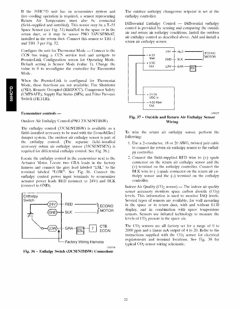
If the 50HC*D unit has an economizer system andfree-cooling operation is required, a sensor representing
Return Air Temperature must also be connected(field-supplied and installed). This sensor may be a T-55
Space Sensor (see Fig. 31) installed in the space or in thereturn duct, or it may be sensor PNO 33ZCSENSAT,installed in the return duct. Connect this sensor to TBI-1
and TB1-3 per Fig. 32.
Configure the unit for Thermostat Mode I Connect to theCCN bus using a CCN service tool and navigate toPremierLink Configuration screen for Operating Mode.Default setting is Sensor Mode (value 1). Change thevalue to 0 to reconfigure the controller for ThermostatMode.
When the PremierLink is configured for ThermostatMode, these functions are not available: Fire Shutdown(FSD), Remote Occupied (RMTOCC), Compressor Safety(CMPSAFE), Supply Fan Status (SFS), and Filter PressureSwitch (FILTER).
Economizer controls i
Outdoor Air Enthalpy Control (PNO 33CSENTHSW) -
The enthalpy control (33CSENTHSW) is available as afield-installed accessory to be used with the EconoMi$er2damper system. The outdoor air enthalpy sensor is part ofthe enthalpy control. (The separate field-installedaccessory return air enthalpy sensor (33CSENTSEN) isrequired for differential enthalpy control. See Fig. 36.)
Locate the enthalpy control in the economizer next to the
Actuator Motor. Locate two GRA leads in the factory
harness and connect the gray lead labeled "ESL" to theterminal labeled "LOW". See Fig. 36. Connect the
enthalpy control power input terminals to economizeractuator power leads RED (connect to 24V) and BLK
(connect to GND).
EnthalpySwitch
= RED '_ECONO
BLK ,JMOTOR
GRA_ E__ CTBECON
m Factory Wiring HarnessC09026
Fig. 36 - Enthalpy Switch (33CSENTHSW) Connections
The outdoor enthalpy changeover setpoint is set at theenthalpy controller.
Differential Enthalpy Control I Differential enthalpycontrol is provided by sensing and comparing the outside
air and return air enthalpy conditions. Install the outdoor
air enthalpy control as described above. Add and install areturn air enthalpy sensor.
- 4-20Main
+ VDCOut
+ 24-36VDC In
- 4-20 MainOut
|24V ? RED --'_ECONO
GND T| BLK ,JMOTOR
LOW 1- GRA _
C09027
Fig. 37 - Outside and Return Air Enthalpy SensorWiring
To wire the return air enthalpy sensor, perform thefollowing:
1. Use a 2-conductor, 18 or 20 AWG, twisted pair cableto connect the return air enthalpy sensor to the enthal-
py controller.
2. Connect the field-supplied RED wire to (+) spadeconnector on the return air enthalpy sensor and the
(+) terminal on the enthalpy controller. Connect the
BLK wire to (-) spade connector on the return air en-thalpy sensor and the (-) terminal on the enthalpycontroller.
Indoor Air Quality (CO2 sensor) I The indoor air qualitysensor accessory monitors space carbon dioxide (CO2)levels. This information is used to monitor IAQ levels.
Several types of sensors are available, for wall mountingin the space or in return duct, with and without LCDdisplay, and in combination with space temperaturesensors. Sensors use infrared technology to measure thelevels of CO2 present in the space air.
The CO2 sensors are all factory set for a range of 0 to2000 ppm and a linear mA output of 4 to 20. Refer to theinstructions supplied with the CO2 sensor for electricalrequirements and terminal locations. See Fig. 38 fortypical CO2 sensor wiring schematic.
22
0
H
2 1 O 87654321J3 J4
Q0q0VDC® SIG COM® 4-20mA
NC ] ALARMCOM_, RELAYNO J CONTACTS
O
C08635
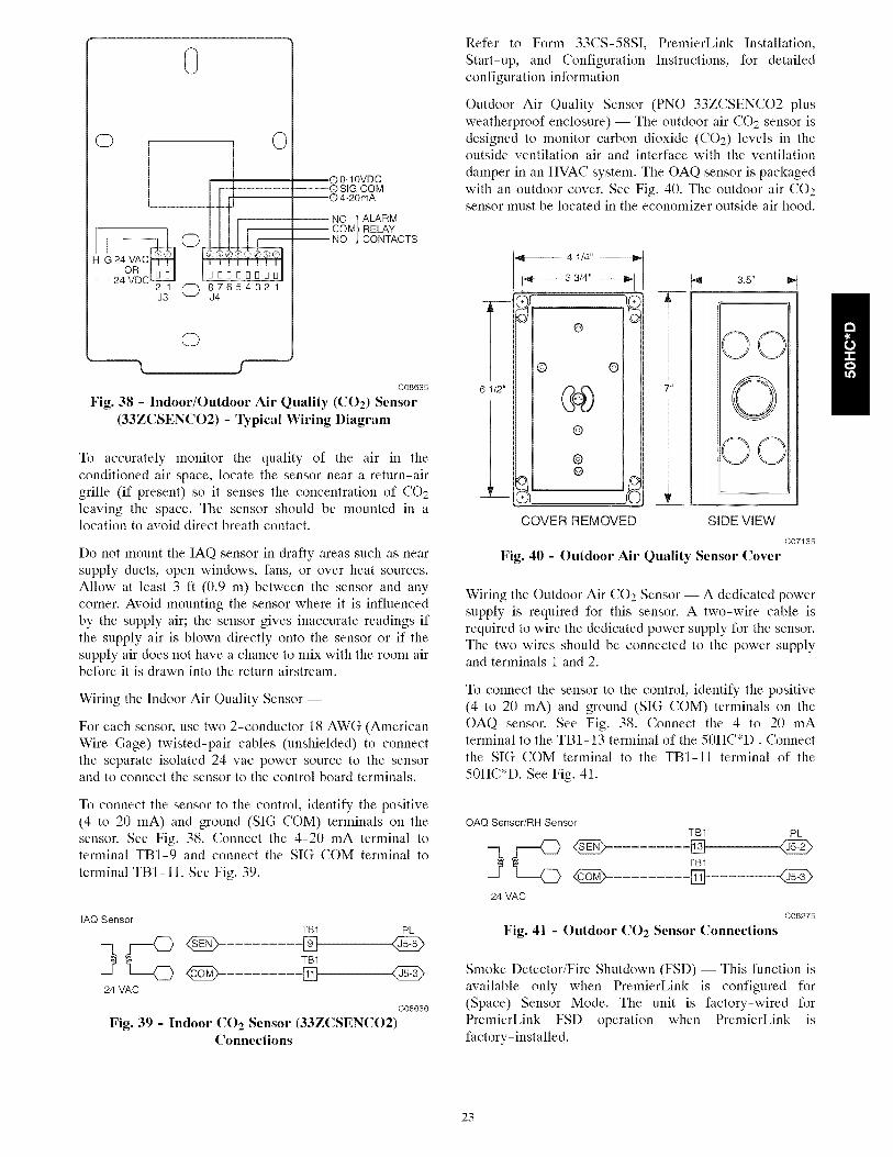
Fig. 38 - Indoor/Outdoor Air Quality (CO2) Sensor
(33ZCSENCO2) - Typical Wiring Diagram
To accurately monitor the quality of the air in the
conditioned air space, locate the sensor near a return-air
grille (if present) so it senses the concentration of CO2leaving the space. The sensor should be mounted in alocation to avoid direct breath contact.
Do not mount the IAQ sensor in drafty areas such as nearsupply ducts, open windows, fans, or over heat sources.
Allow at least 3 ft (0.9 m) between the sensor and anycorner. Avoid mounting the sensor where it is influenced
by the supply air; the sensor gives inaccurate readings ifthe supply air is blown directly onto the sensor or if the
supply air does not have a chance to mix with the room airbefore it is drawn into the return airstream.
Wiring the Indoor Air Quality Sensor --
For each sensor, use two 2-conductor 18 AWG (American
Wire Gage) twisted-pair cables (unshielded) to connectthe separate isolated 24 vac power source to the sensorand to connect the sensor to the control board terminals.
To connect the sensor to the control, identify the positive(4 to 20 mA) and ground (SIG COM) terminals on the
sensor. See Fig. 38. Connect the 4-20 mA terminal toterminal TB1-9 and connect the SIG COM terminal to
terminal TBI-ll. See Fig. 39.
IAQ SensorTB1 PL
TB1<gg> []
24 VAC
C08636
Fig. 39 - Indoor CO2 Sensor (33ZCSENCO2)Connections
Refer to Form 33CS-58SI, PremierLink Installation,Start-up, and Configuration Instructions, for detailedconfiguration information
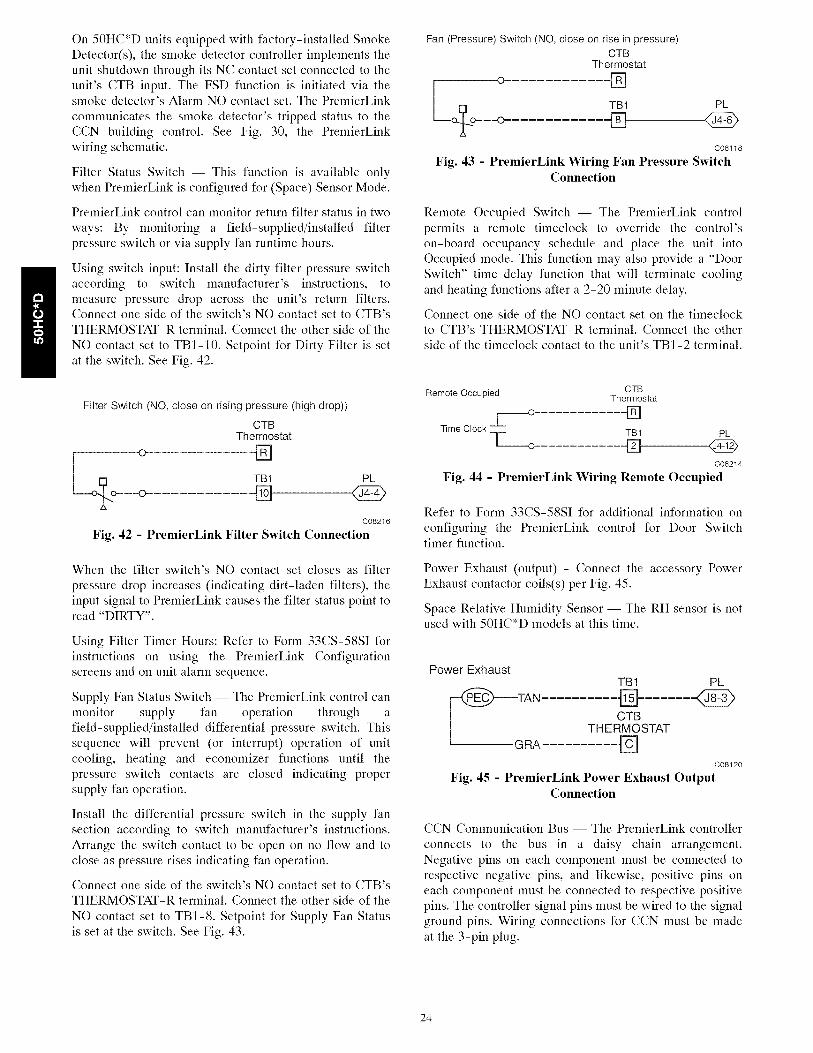
Outdoor Air Quality Sensor (PNO 33ZCSENCO2 plusweatherproof enclosure) -- The outdoor air CO2 sensor isdesigned to monitor carbon dioxide (CO2) levels in theoutside ventilation air and interface with the ventilation
damper in an HVAC system. The OAQ sensor is packagedwith an outdoor cover. See Fig. 40. The outdoor air CO2sensor must be located in the economizer outside air hood.
61t2"
_1-- 41/4" ......................t_
_4_---- 33/4" --_b,,]
© @
@@
@
COVER REMOVED
--,--
7 u
...... 3.5" ........
OC
OOO
SIDE VIEW
C07135
Fig. 40 - Outdoor Air Quality Sensor Cover
Wiring the Outdoor Air CO2 Sensor -- A dedicated powersupply is required for this sensor. A two-wire cable isrequired to wire the dedicated power supply for the sensor.The two wires should be connected to the power supplyand terminals 1 and 2.
To connect the sensor to the control, identify the positive(4 to 20 mA) and ground (SIG COM) terminals on the
OAQ sensor. See Fig. 38. Connect the 4 to 20 mAterminal to the TB1-13 terminal of the 50HC*D. Connectthe SIG COM terminal to the TBI-ll terminal of the
50HC*D. See Fig. 41.
OAQ Sensor/RH SensorTB1 PL
TB1
@ Fq24 VAC
C08275
Fig. 41 - Outdoor CO 2 Sensor Connections
Smoke Detector/Fire Shutdown (FSD) -- This function is
available only when PremierLink is configured for(Space) Sensor Mode. The unit is factory-wired for
PremierLink FSD operation when PremierLink is
factory-installed.
23
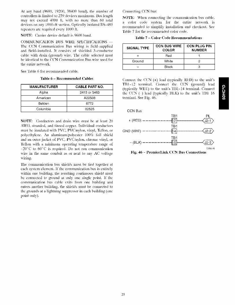
On 50HC*D units equipped with factory-installed SmokeDetector(s), the smoke detector controller implements the
unit shutdown through its NC contact set connected to theunit's CTB input. The FSD function is initiated via thesmoke detector's Alarm NO contact set. The PremierLink
communicates the smoke detector's tripped status to the
CCN building control. See Fig. 30, the PremierLinkwiring schematic.
Filter Status Switch I This function is available onlywhen PremierLink is configured for (Space) Sensor Mode.
PremierLink control can monitor return filter status in two
ways: By monitoring a field-supplied/installed filter
pressure switch or via supply fan runtime hours.
Using switch input: Install the dirty filter pressure switchaccording to switch manufacturer's instructions, to
measure pressure drop across the unit's return filters.Connect one side of the switch's NO contact set to CTB's
THERMOSTAT-R terminal. Connect the other side of the
NO contact set to TBI-10. Setpoint for Dirty Filter is setat the switch. See Fig. 42.
Filter Switch (NO, close on rising pressure (high drop))
CTBThermostat
° TB1 PL
[] @C08216
Fig. 42 - PremierLink Filter Switch Connection
When the filter switch's NO contact set closes as filter
pressure drop increases (indicating dirt-laden filters), the
input signal to PremierLink causes the filter status point toread "DIRTY".
Using Filter Timer Hours: Refer to Form 33CS-58SI for
instructions on using the PremierLink Configurationscreens and on unit alarm sequence.
Supply Fan Status Switch I The PremierLink control can
monitor supply fan operation through afield-supplied/installed differential pressure switch. This
sequence will prevent (or interrupt) operation of unitcooling, heating and economizer functions until the
pressure switch contacts are closed indicating propersupply fan operation.
Install the differential pressure switch in the supply fan
section according to switch manufacturer's instructions.Arrange the switch contact to be open on no flow and to
close as pressure rises indicating fan operation.
Connect one side of the switch's NO contact set to CTB'sTHERMOSTAT-R terminal. Connect the other side of the
NO contact set to TB1-8. Setpoint for Supply Fan Statusis set at the switch. See Fig. 43.
Fan (Pressure) Switch (NO, close on rise in pressure)CTB
Thermostat
o []
L_o--- TB1--0- []
C08118
Fig. 43 - PremierLink Wiring Fan Pressure SwitchConnection
Remote Occupied Switch I The PremierLink controlpermits a remote timeclock to override the control's
on-board occupancy schedule and place the unit intoOccupied mode. This function may also provide a "Door
Switch" time delay function that will terminate cooling
and heating functions after a 2-20 minute delay.
Connect one side of the NO contact set on the timeclockto CTB's THERMOSTAT-R terminal. Connect the other
side of the timeclock contact to the unit's TB1-2 terminal.
Remote Occupied CTBThermostat
TB1 PLTime Clock C[_ -O- [] @
C08214
Fig. 44 - PremierLink Wiring Remote Occupied
Refer to Form 33CS-58SI for additional information on
configuring the PremierLink control for Door Switchtimer function.
Power Exhaust (output) - Connect the accessory PowerExhaust contactor coils(s) per Fig. 45.
Space Relative Humidity Sensor I The RH sensor is notused with 50HC*D models at this time.
Power ExhaustTB1 PL
TAN tN <2DCTB
THERMOSTAT
GRA {_
C08120
Fig. 45 - PremierLink Power Exhaust OutputConnection
CCN Communication Bus I The PremierLink controller
connects to the bus in a daisy chain arrangement.Negative pins on each component must be connected to
respective negative pins, and likewise, positive pins oneach component must be connected to respective positive
pins. The controller signal pins must be wired to the signalground pins. Wiring connections for CCN must be made
at the 3-pin plug.
24
At any baud (9600, 19200, 38400 baud), the number ofcontrollers is limited to 239 devices maximum. Bus length
may not exceed 4000 It, with no more than 60 totaldevices on any 1000-ft section. Optically isolated RS-485
repeaters are required every 1000 ft.
NOTE: Carrier device default is 9600 band.
COMMUNICATION BUS WIRE SPECIFICATIONS --
The CCN Communication Bus wiring is field-suppliedand field-installed. It consists of shielded 3-conductor
cable with drain (ground) wire. The cable selected mustbe identical to the CCN Communication Bus wire used for
the entire network.
See Table 6 for recommended cable.
Table 6 - Recommended Cables
MANUFACTURER CABLE PART NO.
Alpha 2413 or 5463
American A22503
Belden 8772
Columbia 02525
NOTE: Conductors and drain wire must be at least 20
AWG, stranded, and tinned copper. Individual conductors
must be insulated with PVC, PVC/nylon, vinyl, Teflon, or
polyethylene. An aluminum/polyester 100% foil shield
and an outer jacket of PVC, PVC/nylon, chrome vinyl, or
Teflon with a minimum operating temperature range of
-20°C to 60°C is required. Do not run communication
wire in the same conduit as or next to any AC voltage
wiring.
The communication bus shields must be tied together ateach system element. If the communication bus is entirely
within one building, the resulting continuous shield must
be connected to ground at only one single point. If thecommunication bus cable exits from one building and
enters another building, the shields must be connected tothe grounds at a lightning suppressor in each building (one
point only).
Connecting CCN bus:
NOTE: When connecting the communication bus cable,
a color code system for the entire network is
recommended to simplify installation and checkout. SeeTable 7 for the recommended color code.
Table 7 - Color Code Recommendations
CCN BUS WIRE CCN PLUG PINSIGNAL TYPE
COLOR NUMBER
+ Red 1
Ground White 2
- Black 3
Connect the CCN (+) lead (typically RED) to the unit's I
TBI-12 terminal. Connect the CCN (ground) lead
/
(typically WHT) to the unit's TBI-14 terminal. Connect
the CCN (-) lead (typically BLK) to the unit's TBI-16
terminal. See Fig. 46.
CCN Bus
TB1 PL
+ (RED) "D
TB1
GND (WHT) '[_m
TB1
C08276
Fig. 46 I PremierLink CCN Bus Connections
25
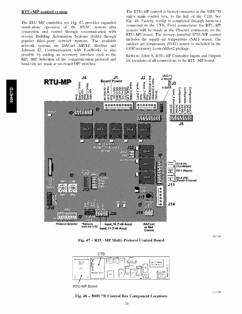
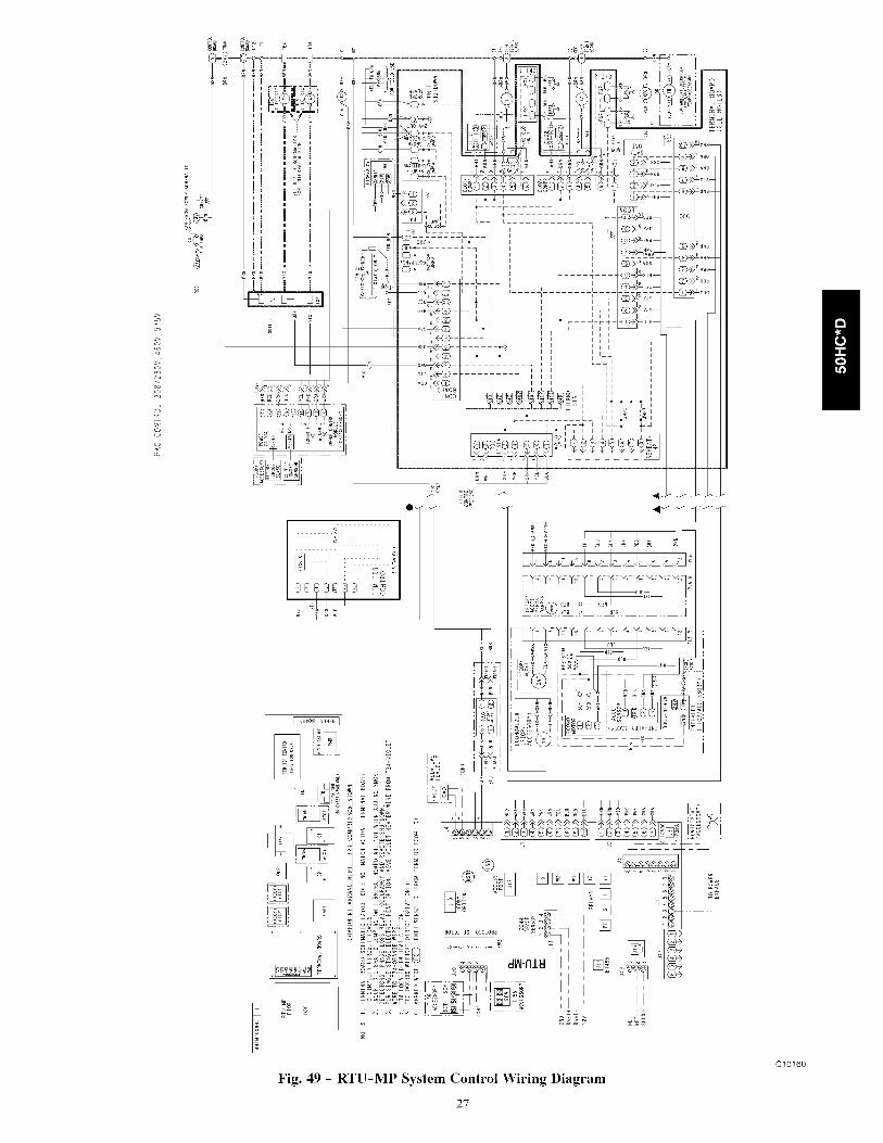
RTU-MP control system
The RTU-MP controller, see Fig. 47, provides expandedstand-alone operation of the HVAC system plus
connection and control through communication with
several Building Automation Systems (BAS) throughpopular third-party network systems. The available
network systems are BACnet MP/TR Modbus andJohnson J2. Communication with LonWorks is also
possible by adding an accessory interface card to theRTU-MP. Selection of the communication protocol andbaud rate are made at on-board DIP switches.
The RTU-MP control is factory-mounted in the 50HC*Dunit's main control box, to the left of the CTB. See
Fig. 48. Factory wiring is completed through harnessesconnected to the CTB. Field connections for RTU-MP
sensors will be made at the Phoenix connectors on the
RTU-MP board. The factory-installed RTU-MP control
includes the supply-air temperature (SAT) sensor. Theoutdoor air temperature (OAT) sensor is included in the
FIOP/accessory EconoMi$er2 package.
Refer to Table 8, RTU-MP Controller Inputs and Outputsfor locations of all connections to the RTU-MP board.
J4 :m (AO-1)9 _ o-10VDC
= J3
J5
DO-6 (H)(Humidistat)
DO-;' (Spare)
111041(PE)Power Exhaust)
Jll
J14
Protocol Selector *Remove InpuL10 (T-55 A_y) BACnet
both for O-5V InpuLtl (T_S Accy) or NetComm
Fig. 47 - RTU-MP Multi-Protocol Control Board
C07129
CTB
RTU-MP
FlOP
RTU-MP Board
I I 71
I .....I I ll -Jl 'll Jr q
Fig. 48 - 50HC*D Control Box Component Locations
26
C10159
t_
>*o
>o
coo
#
o
<
_IYI T0_ _i_ /!i iiii /
!ii i ttI!i i iI !1 /Wi i nLi_y_ Ud H
=
8
o
L
=
I_@L
o
_ I_F
¢€
Fig. 49 - RTU-MP System Control Wiring Diagram
27
C10160
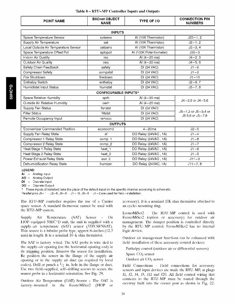
Table 8 - RTU-MP Controller Inputs and Outputs
POINT NAME BACnet OBJECT TYPE OF I/O CONNECTION PINNAME NUMBERS
INPUTS
Space Temperature Sensor sptsens AI (10K Thermistor) J20-1,2
Supply Air Temperature sat AI (10K Thermistor) J2-1,2
Local Outside Air Temperature Sensor oatsens AI (10K Thermistor) J2-3, 4
Space Temperature Offset Pot sptopot AI (lOOK Potentiometer) J20-3
Indoor Air Quality iaq AI (4-20 ma) J4-2, 3
Outdoor Air Quality oaq AI (4-20 ma) J4-5, 6
Safety Chain Feedback safety DI (24 VAC) J1-9
Compressor Safety compstat DI (24 VAC) J1-2
Fire Shutdown firedown DI (24 VAC) J1 - 10
Enthatpy Switch enthatpy DI (24 VAC) J2-6, 7
Humidistat Input Status humstat DI (24 VAC) J5-7, 8
CONFIGURABLE INPUTS*
Space Relative Humidity sprh AI (4-20 ma)J4-2,3 or J4-5,6
Outside Air Relative Humidity oarh AI (4-20 ma)
Supply Fan Status fanstat DI (24 VAC)
Filter Status filtstat DI (24 VAC) J5-1,2 or J5-3,4 orJ5 5,6 or J5-7,8
Remote Occupancy Input remocc DI (24 VAC)
OUTPUTS
econocmd 4-20ma J2-5
sf DO Relay (24VAC, 1A) J1-4
comp_l DO Relay (24VAC, 1A) J1-8
comp_2 DO Relay (24VAC, 1A) J1-7
heat_l DO Relay (24VAC, 1A) J1-6
heat_2 DO Relay (24VAC, 1A) J1-5
aux_2 DO Relay (24VAC, 1A) J11-3
humizer DO Relay (24VAC, 1A) J11-7, 8
Economizer Commanded Position
Supply Fan Relay State
Compressor 1 Relay State
Compressor 2 Relay State
Heat Stage 1 Relay State
Heat Stage 2 Relay State
Power Exhaust Relay State
Dehumidification Relay State
LEGEND
AI - Analog Input
AO - Analog OutputDI - Discrete InputDO - Discrete Output* These inputs (if installed) take the place of the default input on the specific channel according to schematic.Parallel pins J5-1 = J2-6, J5-3 = J1-10, J5-5 = J1-2 are used for field-installation.
The RTU-MP controller requires the use of a Carrier
space sensor. A standard thermostat cannot be used with
the RTU-MP system.
Supply Air Temperature (SAT) Sensor - OnFIOP-equipped 50HC*D unit, the unit is supplied with asupply-air temperature (SAT) sensor (33ZCSENSAT).This sensor is a tubular probe type, approx 6-inches (12.7mm) in length. It is a nominal 10-k ohm thermistor.
The SAT is factory-wired. The SAT probe is wire-tied tothe supply-air opening (on the horizontal opening end) in
its shipping position. Remove the sensor for installation.Re-position the sensor in the flange of the supply-air
opening or in the supply air duct (as required by localcodes). Drill or punch a 1/2-in. hole in the flange or duct.
Use two field-supplied, self-drilling screws to secure thesensor probe in a horizontal orientation. See Fig. 29.
Outdoor Air Temperature (OAT) Sensor - The OAT is
factory-mounted in the EconoMi$er2 (FIOP or
accessory). It is a nominal 10k ohm thermistor attached toan eyelet mounting ring.
EconoMi$er2 The RTU-MP control is used with
EconoMiSer2 (option or accessory) for outdoor air
management. The damper position is controlled directlyby the RTU-MP control; EconoMi$er2 has no internal
logic device.
Outdoor air management functions can be enhanced with
field-installation of these accessory control devices:
Enthalpy control (outdoor air or differential sensors)
Space CO2 sensor
Outdoor air CO2 sensor
Field Connections Field connections for accessorysensors and input devices are made the RTU-MR at plugs
J1, J2, J4, J5, Jll and J20. All field control wiring thatconnects to the RTU-MP must be routed through the
raceway built into the corner post as shown in Fig. 22.
28
The raceway provides the UL required clearance betweenhigh- and low-voltage wiring. Pass the control wires
through the hole provided in the corner post, then feed thewires thorough the raceway to the RTU-MR Connect tothe wires to the removable Phoenix connectors and then
reconnect the connectors to the board.
Space Temperature (SPT) Sensors
A field-supplied Carrier space temperature sensor isrequired with the RTU-MP to monitor space temperature.There are 3 sensors available for this application:
• 33ZCT55SPT, space temperature sensor with override
button
• 33ZCT56SPT, space temperature sensor with override
button and setpoint adjustment
• 33ZCT59SPT, space temperature sensor with LCD
(liquid crystal display) screen, override button, and
setpoint adjustment
Use 20 gauge wire to connect the sensor to the controller.
The wire is suitable for distances of up to 500 ft. Use athree-conductor shielded cable for the sensor and setpoint
adjustment connections. If the setpoint adjustment(slidebar) is not required, then an unshielded, 18 or 20
gauge, two-conductor, twisted pair cable may be used.
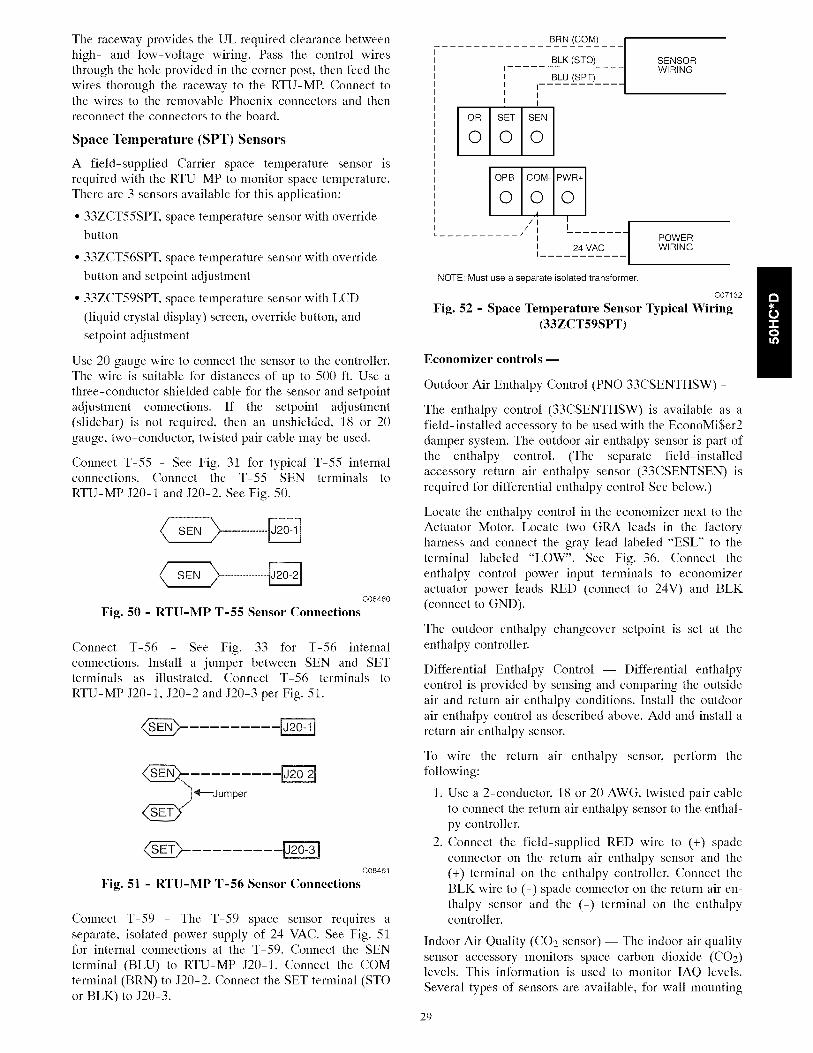
Connect T-55 - See Fig. 31 for typical T-55 internalconnections. Connect the T-55 SEN terminals to
RTU-MP J20-1 and J20-2. See Fig. 50.
C08460
Fig. 50 - RTU-MP T-55 Sensor Connections
Connect T-56 See Fig. 33 for T-56 internalconnections. Install a jumper between SEN and SETterminals as illustrated. Connect T-56 terminals to
RTU-MP J20-1, J20-2 and J20-3 per Fig. 51.
"i,_---Jumper
C08461
Fig. 51 - RTU-MP T-56 Sensor Connections
Connect T-59 - The T-59 space sensor requires a
separate, isolated power supply of 24 VAC. See Fig. 51for internal connections at the T-59. Connect the SEN
terminal (BLU) to RTU-MP J20-1. Connect the COMterminal (BRN) to J20-2. Connect the SET terminal (STO
or BLK) to J20-3.
BRN (COM)
BLK (STO)II BLU (SPT)I II II I
OR SET SEN
ioooOPB COM- PWR+
ooo/ I I
........... JI
i 24 VACI
SENSORWIRING
POWERWIRING
NOTE: Must use a separate isolated transformer.
C07132
Fig. 52 - Space Temperature Sensor Typical Wiring(33ZCT59SPT)
Economizer controls --
Outdoor Air Enthalpy Control (PNO 33CSENTHSW) -
The enthalpy control (33CSENTHSW) is available as a
field-installed accessory to be used with the EconoMi$er2damper system. The outdoor air enthalpy sensor is part of
the enthalpy control. (The separate field-installedaccessory return air enthalpy sensor (33CSENTSEN) is
required for differential enthalpy control See below.)
Locate the enthalpy control in the economizer next to theActuator Motor. Locate two GRA leads in the factory
harness and connect the gray lead labeled "ESL" to the
terminal labeled "LOW". See Fig. 36. Connect theenthalpy control power input terminals to economizer
actuator power leads RED (connect to 24V) and BLK(connect to GND).
The outdoor enthalpy changeover setpoint is set at the
enthalpy controller.
Differential Enthalpy Control -- Differential enthalpy
control is provided by sensing and comparing the outsideair and return air enthalpy conditions. Install the outdoor
air enthalpy control as described above. Add and install a
return air enthalpy sensor.
To wire the return air enthalpy sensor, perform the
following:
1. Use a 2-conductor, 18 or 20 AWG, twisted pair cable
to connect the return air enthalpy sensor to the enthal-
py controller.
2. Connect the field-supplied RED wire to (+) spade
connector on the return air enthalpy sensor and the(+) terminal on the enthalpy controller. Connect the
BLK wire to (-) spade connector on the return air en-
thalpy sensor and the (-) terminal on the enthalpycontroller.
Indoor Air Quality (CO2 sensor) -- The indoor air qualitysensor accessory monitors space carbon dioxide (CO2)levels. This information is used to monitor IAQ levels.Several types of sensors are available, for wall mounting
29
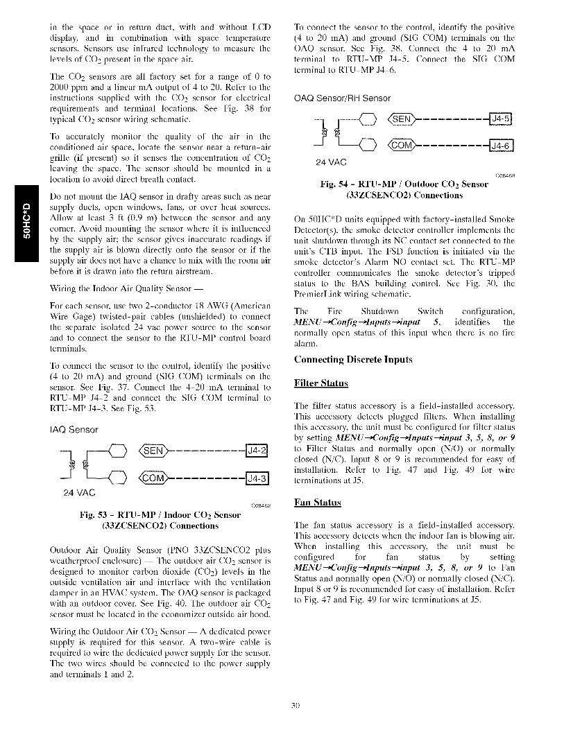
in the space or in return duct, with and without LCDdisplay, and in combination with space temperature
sensors. Sensors use infrared technology to measure thelevels of CO2 present in the space air.
The CO2 sensors are all factory set for a range of 0 to2000 ppm and a linear mA output of 4 to 20. Refer to theinstructions supplied with the CO2 sensor for electricalrequirements and terminal locations. See Fig. 38 fortypical CO2 sensor wiring schematic.
To accurately monitor the quality of the air in theconditioned air space, locate the sensor near a return-airgrille (if present) so it senses the concentration of CO2leaving the space. The sensor should be mounted in alocation to avoid direct breath contact.
Do not mount the IAQ sensor in drafty areas such as near
supply ducts, open windows, fans, or over heat sources.Allow at least 3 ft (0.9 m) between the sensor and any
corner. Avoid mounting the sensor where it is influenced
by the supply air; the sensor gives inaccurate readings ifthe supply air is blown directly onto the sensor or if the
supply air does not have a chance to mix with the room airbefore it is drawn into the return airstream.
Wiring the Indoor Air Quality Sensor --
For each sensor, use two 2-conductor 18 AWG (AmericanWire Gage) twisted-pair cables (unshielded) to connect
the separate isolated 24 vac power source to the sensorand to connect the sensor to the RTU-MP control boardterminals.
To connect the sensor to the control, identify the positive(4 to 20 mA) and ground (SIG COM) terminals on thesensor. See Fig. 37. Connect the 4-20 mA terminal toRTU-MP J4-2 and connect the SIG COM terminal to
RTU-MP J4-3. See Fig. 53.
IAQ Sensor
24 VACC08462
Fig. 53 - RTU-MP / Indoor CO 2 Sensor(33ZCSENCO2) Connections
Outdoor Air Quality Sensor (PNO 33ZCSENCO2 plusweatherproof enclosure) -- The outdoor air CO2 sensor isdesigned to monitor carbon dioxide (CO2) levels in theoutside ventilation air and interface with the ventilation
damper in an HVAC system. The OAQ sensor is packagedwith an outdoor cover. See Fig. 40. The outdoor air CO2sensor must be located in the economizer outside air hood.
Wiring the Outdoor Air CO2 Sensor -- A dedicated powersupply is required for this sensor. A two-wire cable isrequired to wire the dedicated power supply for the sensor.The two wires should be connected to the power supplyand terminals 1 and 2.
To connect the sensor to the control, identify the positive(4 to 20 mA) and ground (SIG COM) terminals on theOAQ sensor. See Fig. 38. Connect the 4 to 20 mAterminal to RTU-MP J4-5. Connect the SIG COMterminal to RTU-MP J4-6.
OAQ Sensor/Fill Sensor
24 VACC08463
Fig. 54 - RTU-MP / Outdoor CO2 Sensor(33ZCSENCO2) Connections
On 50HC*D units equipped with factory-installed Smoke
Detector(s), the smoke detector controller implements theunit shutdown through its NC contact set connected to the
unit's CTB input. The FSD function is initiated via thesmoke detector's Alarm NO contact set. The RTU-MP
controller communicates the smoke detector's tripped
status to the BAS building control. See Fig. 30, thePremierLink wiring schematic.
The Fire Shutdown Switch configuration,MENU-_onfig-_Inputs-,qnput 5, identifies the
normally open status of this input when there is no firealarm.
Connecting Discrete Inputs
Filter Status
The filter status accessory is a field-installed accessory.
This accessory detects plugged filters. When installingthis accessory, the unit must be configured for filter status
by setting MENU-_onfig-_Inputs--_input 3, 5, 8, or 9
to Filter Status and normally open (N/O) or normallyclosed (N/C). Input 8 or 9 is recommended for easy of
installation. Refer to Fig. 47 and Fig. 49 for wireterminations at J5.
Fan Status
The fan status accessory is a field-installed accessory.This accessory detects when the indoor fan is blowing air.When installing this accessory, the unit must beconfigured for fan status by settingMENU-_onfig-_Inputs-,input 3, 5, 8, or 9 to FanStatus and normally open (N/O) or normally closed (N/C).Input 8 or 9 is recommended for easy of installation. Referto Fig. 47 and Fig. 49 for wire terminations at J5.
3O
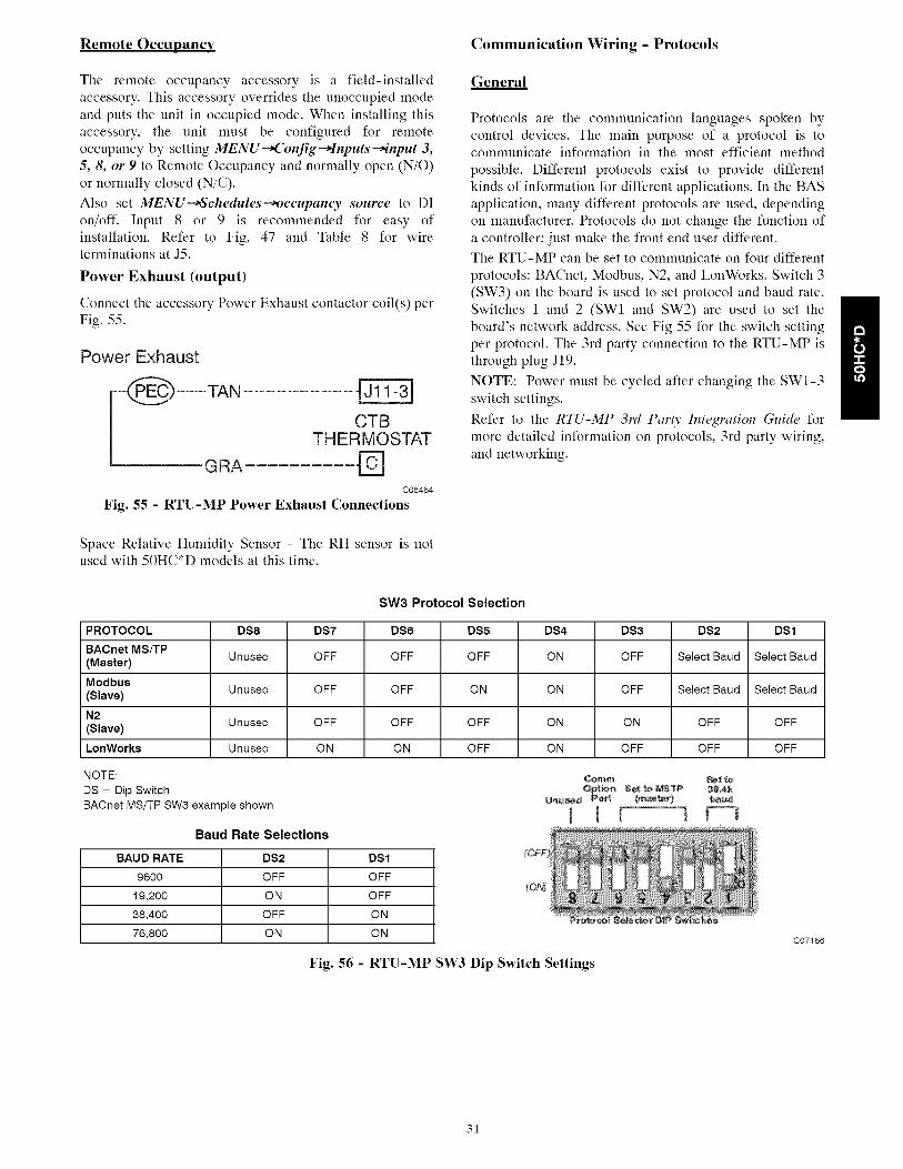
Remote Occupancy Communication Wiring - Protocols
The remote occupancy accessory is a field-installed
accessory. This accessory overrides the unoccupied mode
and puts the unit in occupied mode. When installing thisaccessory, the unit must be configured for remote
occupancy by setting MENU_Config-_Inputs--,input 3,5, 8, or 9 to Remote Occupancy and normally open (N/O)
or normally closed (N/C).
Also set MENU--_Schedules--_occupancy source to DI
on/off. Input 8 or 9 is recommended for easy of
installation. Refer to Fig. 47 and Table 8 for wireterminations at J5.
Power Exhaust (output)
Connect the accessory Power Exhaust contactor coil(s) perFig. 55.
Power Exhaust
TAN
CTBTHERMOSTAT
GRA
C08464
Fig. 55 - RTU-MP Power Exhaust Connections
General
Protocols are the communication languages spoken by
control devices. The main purpose of a protocol is tocommunicate information in the most efficient method
possible. Different protocols exist to provide differentkinds of information for different applications. In the BAS
application, many different protocols are used, dependingon manufacturer. Protocols do not change the function of
a controller; just make the front end user different.
The RTU-MP can be set to communicate on four different
protocols: BACnet, Modbus, N2, and LonWorks. Switch 3
(SW3) on the board is used to set protocol and baud rate.
Switches 1 and 2 (SWl and SW2) are used to set theboard's network address. See Fig 55 for the switch setting
per protocol. The 3rd party connection to the RTU-MP isthrough plug J19.
NOTE: Power must be cycled after changing the SW1-3
switch settings.
Refer to the RTU-MP 3rd Part)' Integration Guide for
more detailed information on protocols, 3rd party wiring,and networking.
Space Relative Humidity Sensor - The RH sensor is notused with 50HC*D models at this time.
SW3 Protocol Selection
PROTOCOL DS8 DS7 DS6 DS5 DS4 DS3 DS2 DS1
BACnet MS[FP Unused OFF OFF OFF ON OFF Select Baud Select Baud(Master)
ModbusUnused OFF OFF ON ON OFF Select Baud Select Baud
(Slave)
N2Unused OFF OFF OFF ON ON OFF OFF
(Slave)
LonWorks Unused ON ON OFF ON OFF OFF OFF
NOT E: ¢_n_m _DS = Dip Switch Opt_ S_ _ NSTP 3&4_
BAOnet MS/TP SW3 example shown J J [ 1
Baud Rate Selections
BAUD RATE DS2 DS1
9600 OFF OFF
19,200 ON OFF
38,400 OFF ON
76,800 ON ON
(ON)
Fig. 56 - RTU-MP SW3 Dip Switch Settings
C07166
31
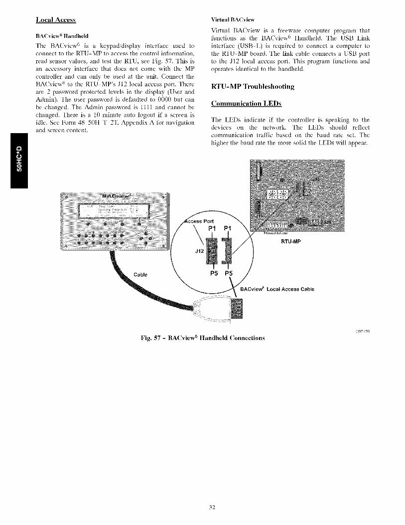
Local Access
BACview 6 Handheld
The BACview 6 is a keypad/display interface used toconnect to the RTU-MP to access the control information,read sensor values, and test the RTU, see Fig. 57. This isan accessory interface that does not come with the MPcontroller and can only be used at the unit. Connect theBACview 6 to the RTU-MP's J12 local access port. Thereare 2 password protected levels in the display (User andAdmin). The user password is defaulted to 0000 but canbe changed. The Admin password is 1111 and cannot bechanged. There is a 10 minute auto logout if a screen isidle. See Form 48-50H-T-2T, Appendix A for navigationand screen content.
Virtual BACview
Virtual BACview is a freeware computer program thatfunctions as the BACview 6 Handheld. The USB Link
interface (USB-L) is required to connect a computer to
the RTU-MP board. The link cable connects a USB portto the J12 local access port. This program functions and
operates identical to the handheld.
RTU-MP Troubleshooting
Communication LEDs
The LEDs indicate if the controller is speaking to thedevices on the network. The LEDs should reflect
communication traffic based on the baud rate set. The
higher the baud rate the more solid the LEDs will appear.
Port
P1
J12
PIProtocol Selector
RTU-MP
Cable P5 P5
BACview s Loca| Access CaNe
Fig. 57 - BACview 6 Handheld ConnectionsC07170
32
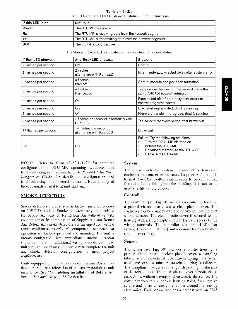
Table 9 - LEDsThe LEDs on the RTU-MP show the status of certain functions
If this LED is on... Status is...
Power The RTU MP has power
Rx The RTU MP is receiving data from the network segment
Tx The RTU MP is transmitting data over the network segment
DO# The digital output is active
The Run and Error LEDs indicate control module and network status
If Run LED shows... And Error LED shows... Status is...
2 flashes per second Off Normal
2 flashes,2 flashes per second alternating with Run LED Five minute auto-restart delay after system error
3 flashes, Control module has just been formatted2 flashes per second then off
4 flashes, Two or more devices on this network have the2 flashes per second then pause same ARC156 network address
Exec halted after frequent system errors or2 flashes per second On control programs halted
5 flashes per second On Exec start-up aborted, Boot is running
5 flashes per second Off Firmware transfer in progress, Boot is running
7 flashes per second 7 flashes per second, alternating with Ten second recovery period after brownoutRun LED
14 flashes per second, Brownout14 flashes per second alternating with Run LED
On On
Failure. Try the following solutions:• Turn the RTU-MP off, then on.• Format the RTU- MR
• Download memory to the RTU-MR• Replace the RTU- MR
NOTE: Refer to Form 48-50H-T-2T for completeconfiguration of RTU-ME operating sequences and
troubleshooting information. Refer to RTU-MP 3rd Party
Integration Guide for details on configuration and
troubleshooting of connected networks. Have a copy of
these manuals available at unit start-up.
SMOKE DETECTORS
Smoke detectors are available as factory-installed optionson 50HC*D models. Smoke detectors may be specified
for Supply Air only or for Return Air without or witheconomizer or in combination of Supply Air and Return
Air. Return Air smoke detectors are arranged for verticalreturn configurations only. All components necessary for
operation are factory-provided and mounted. The unit is
factory-configured for immediate smoke detectorshutdown operation; additional wiring or modifications to
unit terminal board may be necessary to complete the unitand smoke detector configuration to meet project
requirements.
Units equipped with factory-optional Return Air smokedetectors require a relocation of the sensor module at unit
installation. See "Completing Installation of Return Air
Smoke Sensor:" on page 35 for details.
System
The smoke detector system consists of a four-wire
controller and one or two sensors. Its primary function isto shut down the rooftop unit in order to prevent smoke
from circulating throughout the building. It is not to beused as a life saving device.
Controller
The controller (see Fig. 58) includes a controller housing,
a printed circuit board, and a clear plastic cover. Thecontroller can be connected to one or two compatible duct
smoke sensors. The clear plastic cover is secured to thehousing with a single captive screw for easy access to the
wiring terminals. The controller has three LEDs (forPower, Trouble and Alarm) and a manual test/reset button
(on the cover face).
Sensor
The sensor (see Fig. 59) includes a plastic housing, aprinted circuit board, a clear plastic cover, a sampling
tube inlet and an exhaust tube. The sampling tube (when
used) and exhaust tube are attached during installation.The sampling tube varies in length depending on the size
of the rooftop unit. The clear plastic cover permits visualinspections without having to disassemble the sensor. The
cover attaches to the sensor housing using four captive
screws and forms an airtight chamber around the sensingelectronics. Each sensor includes a harness with an RJ45
33
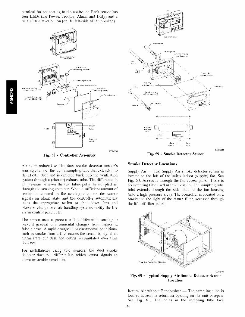
terminal for connecting to the controller. Each sensor hasfour LEDs (for Power, Trouble, Alarm and Dirty) and a
manual test/reset button (on the left-side of the housing).
Duct smoke sensorcontroller
Controller housing
and electronics
Conduit couplings J(supplied by installer)
Fastener J
(2X)
Conduit nuts
_ (supplied by installer)
_D
Conduitsupport plate
_TerminalblockcoverCovergasket
_(ordering option)
t/_ Controller cover
Trouble
Fig. 58 - Controller AssemblyC08208
Air is introduced to the duct smoke detector sensor's
sensing chamber through a sampling tube that extends intothe HVAC duct and is directed back into the ventilation
system through a (shorter) exhaust tube. The difference inair pressure between the two tubes pulls the sampled air
through the sensing chamber. When a sufficient amount of
smoke is detected in the sensing chamber, the sensorsignals an alarm state and the controller automatically
takes the appropriate action to shut down fans andblowers, change over air handling systems, notify the fire
alarm control panel, etc.
The sensor uses a process called differential sensing toprevent gradual environmental changes from triggering
false alarms. A rapid change in environmental conditions,
such as smoke from a fire, causes the sensor to signal analarm state but dust and debris accumulated over time
does not.
For installations using two sensors, the duct smoke
detector does not differentiate which sensor signals analarm or trouble condition.
/ Exhausttube
j Exhaustgasket SensorhousingF and electronics
tSee ]\\
Detail A I _x
\\
Intake
gasket \\\ \ \ \ \ Cover gasket
\\ / (orderingoption)
\ \\\ \\\aa
/Z/ Plug \_\\ \\ j Sensor cover
/_(@_ (ordSeal_pli, ngatu_l_eely) x x\\\\ \\ ......
Magnetic _S" ....................................................................................................."_l_]
rou e irT bl D ty
Fig. 59 - Smoke Detector SensorC08209
Smoke Detector Locations
Supply Air I The Supply Air smoke detector sensor islocated to the left of the unit's indoor (supply) fan. See
Fig. 60. Access is through the fan access panel. There isno sampling tube used at this location. The sampling tube
inlet extends through the side plate of the fan housing
(into a high pressure area). The controller is located on abracket to the right of the return filter, accessed through
the lift-off filter panel.
j/Smoke Detector Sensor
C08245
Fig. 60 - Typical Supply Air Smoke Detector SensorLocation
Return Air without Economizer I The sampling tube islocated across the return air opening on the unit basepan.
See Fig. 61. The holes in the sampling tube face
34
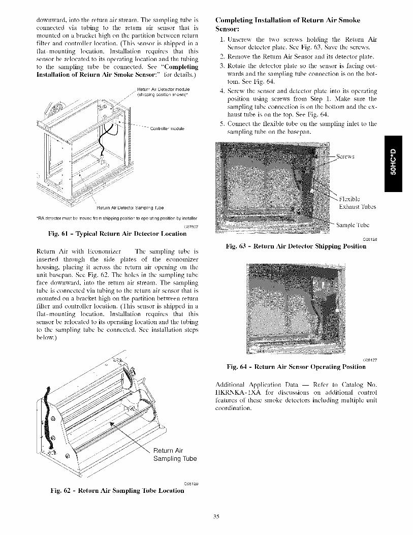
downward,intothereturnairstream.Thesamplingtubeisconnectedvia tubingto the returnair sensorthat ismountedonabrackethighonthepartitionbetweenreturnfilterandcontrollerlocation.(Thissensoris shippedinaflat-mountinglocation.Installationrequiresthat thissensorberelocatedtoitsoperatinglocationandthetubingto thesamplingtubebe connected.See"CompletingInstallationofReturn Air Smoke Sensor:" for details.)
Return Air Detector module
_ (shipping position shown)*
Controller module
Return Air Detector Sampling Tube
*RA detector must be moved from shipping position to operating position by installer
C07307
Fig. 61 - Typical Return Air Detector Location
Return Air with Economizer -- The sampling tube is
inserted through the side plates of the economizerhousing, placing it across the return air opening on the
unit basepan. See Fig. 62. The holes in the sampling tubeface downward, into the return air stream. The sampling
tube is connected via tubing to the return air sensor that is
mounted on a bracket high on the partition between returnfilter and controller location. (This sensor is shipped in a
fiat-mounting location. Installation requires that thissensor be relocated to its operating location and the tubing
to the sampling tube be connected. See installation steps
below.)
Completing Installation of Return Air SmokeSensor:
1. Unscrew the two screws holding the Return Air
Sensor detector plate. See Fig. 63. Save the screws.
2. Remove the Return Air Sensor and its detector plate.
3. Rotate the detector plate so the sensor is facing out-wards and the sampling tube connection is on the bot-
tom. See Fig. 64.
4. Screw the sensor and detector plate into its operatingposition using screws from Step 1. Make sure the
sampling tube connection is on the bottom and the ex-
haust tube is on the top. See Fig. 64.
5. Connect the flexible tube on the sampling inlet to the
sampling tube on the basepan.
Exhaust Tubes
Sample Tube
C08126
Fig. 63 - Return Air Detector Shipping Position
C08127
Fig. 64 - Return Air Sensor Operating Position
Additional Application Data -- Refer to Catalog No.HKRNKA-1XA for discussions on additional control
features of these smoke detectors including multiple unitcoordination.
Return Air
Sampling Tube
C08129
Fig. 62 - Return Air Sampling Tube Location
35
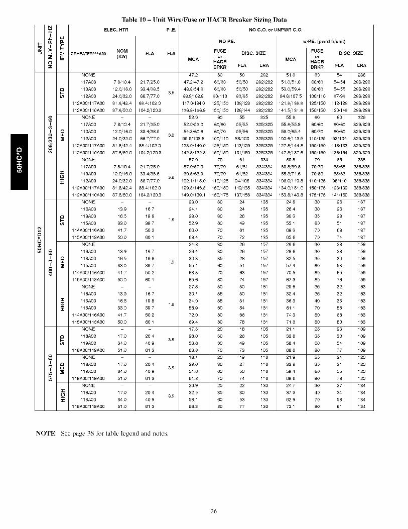
N"1"
_ > _IJ._ CRHEATER***A00
OZ
¢q
1"
o=
Q_OI
O3I a
o uJ
COQ
Table 10 - Unit Wire/Fuse or HACR Breaker Sizing Data
ELEC. HTR P .E. NO C.O. or UNPWR C.O.
NO RE. w/RE. (pwrd fr/unit)
NOM FUSEFLA FLA DISC. SIZE
(KW) MCA orHACRBRKR FLA LRA
FUSE DISC. SIZEor
MCA HACRBRKR FLA LRA
51.0 60 54 286
51.0/51.0 60/60 54/54 286/286
53.0/59.4 60/60 54/55 286/286
94.6/107.5 100/110 87/99 286/286
NONE - -
117A00 7.8/10.4 21.7/25.0
13 110A00 12.0/16.0 33.4/38.5I-,- 3.8
112A00 24.0/32.0 66.7/77.0
112A00/117A00 31.8/42.4 88.4/102.0
112A00/110A00 37.6/50.0 104.2/120.3
NONE - -
117A00 7.8/10.4 21.7/25.0
110A00 12.0/16.0 33.4/38.53.8
112A00 24.0/32.0 66.7/77.0
112A00/117A00 31.8/42.4 88.4/102.0
112A00/110A00 37.6/50.0 104.2/120.3
NONE - -
117A00 7.8/10.4 21.7/25.0
"1- 110A00 12.0/16.0 33.4/38.5t,,,,9 3.8,,_ 112A00 24.0/32.0 66.7/77.0
112A00/117A00 31.8/42.4 88.4/102.0
112A00/110A00 37.6/50.0 104.2/120.3
47.2 60 50 282
47.2/47.2 60/60 50/50 282/282
48.3/54.6 60/60 50/50 282/282
89._102.8 90/110 83/95 282/282
121.8/138.8 125/150 112/128 286/286
141.5/131.6 150/150 130/149 286/286
55.8 60 60 329
55.8/55.8 60/60 60/60 329/329
59.0/65.4 60/70 60/60 329/329
100.6/113.5 110/125 93/104 329/329
127.8/144.8 150/150 118/133 329/329
147.5/137.6 150/150 136/154 329/329
60.8 70 65 338
60.8/60.8 70/70 65/65 338/338
65.3/71.6 70/80 65/66 338/338
106.9/119.8 110/125 98/110 338/338
134.0/151.0 150/175 123/139 338/338
153.8/143.8 175/175 141/160 338/338
117.0/134.0 125/150 108/123 282/282
136.8/126.8 150/150 126/144 282/282
52.0 60 55 325
52.0/52.0 60/60 55/55 325/325
54.3/60.6 60/70 55/56 325/325
95.9/108.8 100/110 88/100 325/325
123.0/140.0 125/150 113/129 325/325
142.8/132.8 150/150 131/150 325/325
57.0 70 61 334
57.0/57.0 70/70 61/61 334/334
60.5/66.9 70/70 61/62 334/334
102.1/115.0 110/125 94/106 334/334
129.3/146.3 150/150 119/135 334/334
149.0/139.1 150/175 137/156 334/334
NONE - - 23.0 30 24 135
116A00 13.9 16.7 24.1 30 24 135
113A00 16.5 19.8 28.0 30 26 1351.8
115A00 33.0 39.7 52.9 60 49 135
114A00/116A00 41.7 50.2 66.0 70 61 135
115A00/113A00 50.0 60.1 63.4 70 72 135
NONE - - 24.8 30 26 157
o 116A00 13.9 16.7 26.4 30 26 157
I a 113A00 16.5 19.8 30.3 35 28 157W 1.8115A00 33.0 39.7 55.1 60 51 157
Q114A00/116A00 41.7 50.2 68.3 70 63 157
115A00/113A00 50.0 60.1 65.6 80 74 157
NONE - - 27.8 30 30 161
116A00 13.9 16.7 30.1 35 30 161
I 113A00 16.5 19.8 34.0 35 31 1611.8
115A00 33.0 39.7 58.9 60 54 161
114A00/116A00 41.7 50.2 72.0 80 66 161
115A00/113A00 50.0 60.1 69.4 80 78 161
NONE - - 17.3 20 18 105
118A00 17.0 20.4 28.0 30 26 1053.8
119A00 34.0 40.9 53.6 60 49 105
118A00/119A00 51.0 61.3 63.8 70 73 105
o NONE - - 18.1 20 19 116
a 118A00 17.0 20.4 29.0 30 27 116I w 3.8
_ 119A00 34.0 40.9 54.6 60 50 116118A00/119A00 51.0 61.3 64.8 70 74 116
NONE - - 20.9 25 22 130
I 118A00 17.0 20.4 32.5 35 30 1303.8
119A00 34.0 40.9 58.1 60 53 130
118A00/119A00 51.0 61.3 68.3 80 77 130
24.8 30 26 137
26.4 30 26 137
30.3 35 28 137
55.1 60 51 137
68.3 70 63 137
65.6 70 74 137
26.6 30 28 159
28.6 30 28 159
32.5 35 30 159
57.4 60 53 159
70.5 80 65 159
67.9 80 76 159
29.6 35 32 163
32.4 35 32 163
36.3 40 33 163
61.1 70 56 163
74.3 80 68 163
71.6 80 80 163
21.1 25 23 109
32.8 35 30 109
58.4 60 54 109
68.6 80 77 109
21.9 25 24 120
33.8 35 31 120
59.4 60 55 120
69.6 80 78 120
24.7 30 27 134
37.3 40 34 134
62.9 70 58 134
73.1 80 81 134
NOTE: See page 38 for table legend and notes.
36
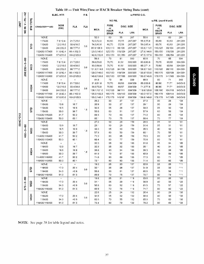
Table 10 -- Unit Wire/Fuse or HACR Breaker Sizing Data (cont)N"I" ELEC. HTR R E. w/PWRD C.O.I
_- =n n NO RE.
I-- I >"> I-- NOM FUSE
:3 _ u..5 CRHEATER***AO0 (KW) FLA FLA or DISC, SIZE0 --Z
Q{DI
03I 13
o =
CO
NONE - -
117A00 7.8/10.4 21.7/25.0
r't 110A00 12.0/16.0 33.4/38.5I--09 112A00 24.0/32.0 66.7/77.0
112A00/117A00 31.8/42.4 88.4/102.0
112A00/110A00 37.6/50.0 104.2/120.3
NONE - -
117A00 7.8/10.4 21.7/25.0
110A00 12.0/16.0 33.4/38.5
112A00 24.0/32.0 66.7/77.0
112A00/117A00 31.8/42.4 88.4/102.0
112A00/110A00 37.6/50.0 104.2/120.3
NONE - -
117A00 7.8/10.4 21.7/25.0
"I" 110A00 12.0/16.0 33.4/38.5L_,,_ 112A00 24.0/32.0 66.7/77.0
112A00/117A00 31.8/42.4 88.4/102.0
112A00/110A00 37.6/50.0 104.2/120.3
NONE - -
116A00 13.9 16.7
113A00 16.5 19.8
115A00 33.0 39.7
114A00/116A00 41.7 50.2
115A00/113A00 50.0 60.1
I NONE - -
o 116A00 13.9 16.7
I a 113A00 16.5 19.87= 115A00 33.0 39.7Q
114A00/116A00 41.7 50.2
115A00/113A00 50.0 60.1
NONE - -
116A00 13.9 16.7
I 113A00 16.5 19.8
115A00 33.0 39.7
114A00/116A00 41.7 50.2
115A00/113A00 50.0 60.1
NONE - -
118A00 17.0 20.4
119A00 34.0 40.9
118A00/119A00 51.0 61.3
o NONE - -
118A00 17.0 20.4a=
I_ 119A00 34.0 40.9
118A00/119A00 51.0 61.3
NONE - -I
118A00 17.0 20.4119A00 34.0 40.9
118A00/119A00 51.0 61.3
MCA HACRBRKR FLA LRA
52.0 60 55 287
52.0/52.0 60/60 55/55 287/287
54.3/60.6 60/70 55/56 287/2873.8
95.9/108.8 100/110 88/100 287/287
123.0/140.0 125/150 113/129 287/287
142.8/132.8 150/150 131/150 287/287
56.8 70 61 330
56.8/56.8 70/70 61/61 330/330
60.3/66.6 70/70 61/61 330/3303.8
101.9/114.8 110/125 94/106 330/330
129.0/146.0 150/150 119/134 330/330
148.8/138.8 150/150 137/155 330/330
61.8 70 66 339
61.8/61.8 70/70 66/66 339/339
66.5/72.9 70/80 66/67 339/3393.8
108.1/121.0 110/125 99/111 339/339
135.3/152.3 150/175 124/140 339/339
155.0/145.1 175/175 143/161 339/339
w/RE. (pwrd fr/unit)
FUSE DISC. SIZEor
MCA HACRBRKR FLA LRA
55.8 60 60 291
55.8/55.8 60/60 60/60 291/291
59.0/65.4 60/70 60/60 291/291
100.6/113.5 110/125 93/104 291/291
127.8/144.8 150/150 118/133 291/291
147.5/137.6 150/150 136/154 291/291
60.6 70 65 334
60.6/60.6 70/70 65/65 334/334
65.0/71.4 70/80 65/66 334/334
106.6/119.5 110/125 98/110 334/334
133.8/150.8 150/175 123/139 334/334
153.5/143.6 175/175 141/160 334/334
65.6 80 71 343
65.6/65.6 80/80 71/71 343/343
71.3/77.6 80/80 71/71 343/343
112.9/125.8 125/150 104/116 343/343
140.0/157.0 150/175 129/144 343/343
159.8/149.8 175/175 147/165 343/343
25.2 30 27 137
26.9 30 27 137
30.8 35 28 1371.8
55.6 60 51 137
68.8 70 63 137
66.1 70 75 137
27.0 30 29 159
29.1 30 29 159
33.0 35 30 1591.8
57.9 60 53 159
71.0 80 65 159
68.4 80 77 159
30.0 35 32 163
32.9 35 32 163
36.8 40 34 1631.8
61.6 70 57 163
74.8 80 69 163
72.1 80 80 163
19.0 25 20 107
30.1 35 28 1073.8
55.8 60 51 107
65.9 70 75 107
19.8 25 21 118
31.1 35 29 1183.8
56.8 60 52 118
66.9 70 76 118
22.6 25 24 132
34.6 35 32 1323.8
60.3 70 55 132
70.4 80 79 132
27.0 30 29 139
29.1 30 29 139
33.0 35 30 139
57.9 60 53 139
71.0 80 65 139
68.4 70 77 139
28.8 35 31 161
31.4 35 31 161
35.3 40 32 161
60.1 70 55 161
73.3 80 67 161
70.6 80 79 161
31.8 35 34 165
35.1 40 34 165
39.0 40 36 165
63.9 70 59 165
77.0 80 71 165
74.4 80 82 165
22.8 25 25 111
34.9 35 32 111
60.5 70 56 111
70.7 80 79 111
23.6 30 26 122
35.9 40 33 122
61.5 70 57 122
71.7 80 80 122
26.4 30 29 136
39.4 40 36 136
65.0 70 60 136
75.2 80 83 136
NOTE: See page 38 for table legend and notes.
37
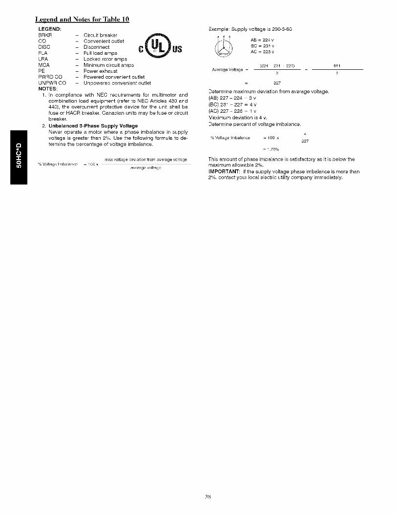
Legend and Notes for Table 10
LEGEND:BRKRCODISCFLALRAMCAPE
- Circuit breaker- Convenient outlet- Disconnect
- Full load amps- Locked rotor amps- Minimum circuit amps- Power exhaust
PWRD CO - Powered convenient outlet
UNPWR CO - Unpowered convenient outletNOTES:
1. In compliance with NEC requirements for multimotor andcombination load equipment (refer to NEC Articles 430 and440), the overcurrent protective device for the unit shall befuse or HACR breaker. Canadian units may be fuse or circuitbreaker.
2. Unbalanced 3-Phase Supply VoltageNever operate a motor where a phase imbalance in supplyvoltage is greater than 2%. Use the following formula to de-termine the percentage of voltage imbalance.
max voltage deviation from average voltage% Voltage imbalance = 1O0 x
average voltage
Example: Supply voltage is 230-3-60
AB = 224 vBC = 231 v
AC = 226 v
Average Voltage =(224 + 231 + 226)
3
681
3
= 227
Determine maximum deviation from average voltage.
(AB) 227 - 224 = 3 v
(BC) 231 - 227 = 4 v
(AC) 227- 226 = 1 v
Maximum deviation is 4 v.
Determine percent of voltage imbalance.
4% Voltage imbalance = 100 x
227
= 1.76%
This amount of phase imbalance is satisfactory as it is below themaximum allowable 2%.
IMPORTANT: If the supply voltage phase imbalance is more than2%, contact your local electric utility company immediately.
38
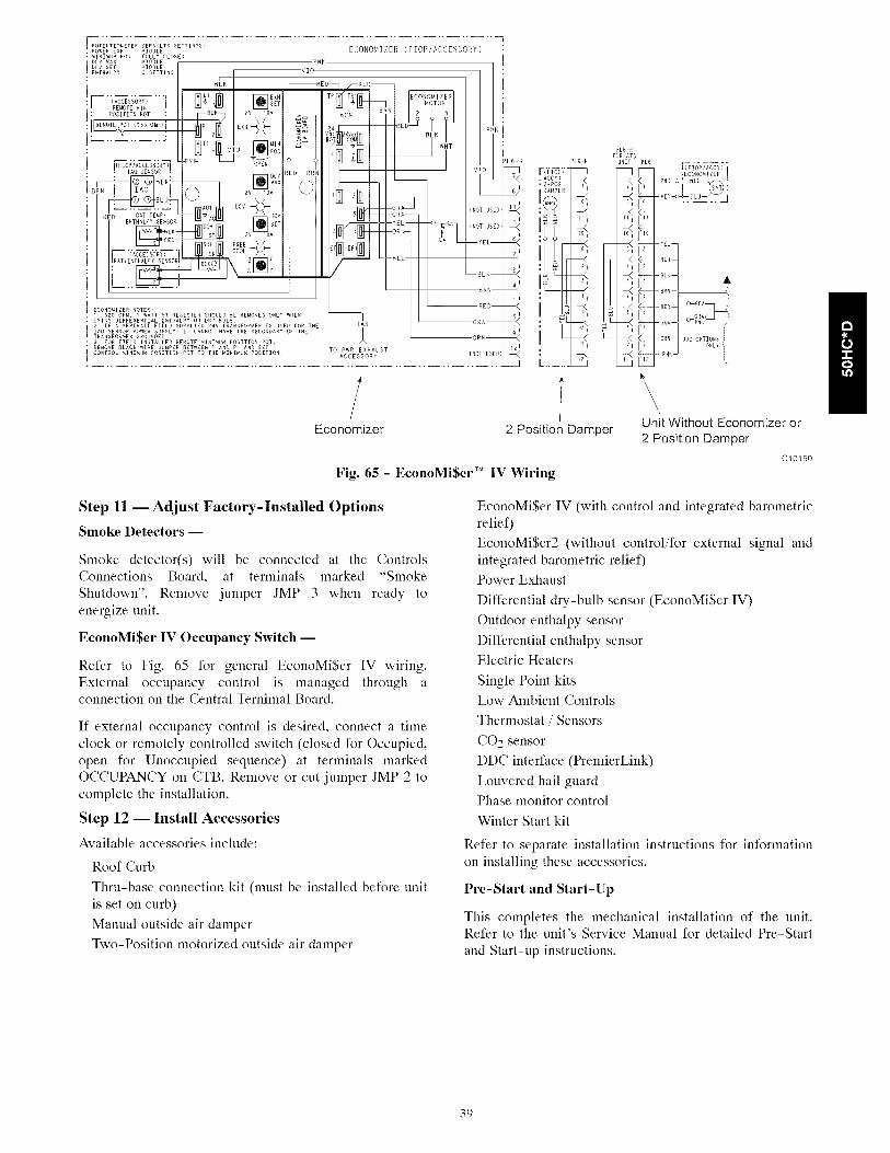
[POTENTIOMETER DEFAULTS SETTINGS:
• POWER EXH MIODLE• MI_IMU_ POE FULLY CLOSED
gCV _A× _IODLEOCV SET _IO_LE
: ENTHALPY C SETTING _LIF_ -
_I EXBi ....E......I F EEI
PNI_
VIO-
EL} BR
ECONOMIZER (FlOP/ACCESSORY)
RI_Tq_
i¢ EIva_
: , , DCRi BL"
• -- S FREE
: : ' A_O
I ECONOMIZER NOTES:• 1 6_o OHm, I WATT 5_ _ESlSTE_ SHOUL_ BE REMOVE_ ONLY WHE_
USING DIFFERENTIAL ENTHALPY OR DRY BULB
i 2 IF A SEPERATE FIELD SUPPLIED 24V TRANSFORMER IS USEO FOR THEIAO SENSOR POWER SUPPLY, IT CANNOT HAVE THE SECONDARY OF THE
TRAnSFORmER GROUR_ED
: 3 FOR FIELD INSTALLED REMOTE MINIMUM POSITION POT,REMOVE BLACK WIRE JUMPER BETWEEN P AN9 P1 AND SET
l CONTROL MINIMUM POSITION POT TO THE MINZMU_ POSITION
i R_T_ErF_EE,F_
lTAN
TO PWR EXHAUSTACCESSORY
PLG-R
, ACCY• 2-PO:I DAMPI
I_[_-i,,%%%<
L......Z
PL6-R
FOR STD
UNIT PL6
_E-
,I_<_--
I I
Economizer 2 Position Damper
Fig. 65 - EconoMi$er TM IV Wiring
,ECONOMIZER [
-P_K--_BLU_,......L_D i
YEL_
BLU_
- BLII --{ _t
-RED_ O-GRA_-GRA_ o-GRApN_
ORR_ I
DDC OPTIONS
ONLY
PNRJ
\Unit Without Economizer or
2 Position Damper
C10150
Step 11 -- Adjust Factory-Installed Options
Smoke Detectors --
Smoke detector(s) will be connected at the ControlsConnections Board, at terminals marked "Smoke
Shutdown". Remove jumper JMP 3 when ready to
energize unit.
EconoMiSer IV Occupancy Switch --
Refer to Fig. 65 for general EconoMi$er IV wiring.
External occupancy control is managed through aconnection on the Central Ternimal Board.
If external occupancy control is desired, connect a timeclock or remotely controlled switch (closed for Occupied,open for Unoccupied sequence) at terminals markedOCCUPANCY on CTB. Remove or cut jumper JMP 2 tocomplete the installation.
Step 12 -- Install Accessories
Available accessories include:
Roof Curb
Thru-base connection kit (must be installed before unit
is set on curb)
Manual outside air damper
Two-Position motorized outside air damper
EconoMi$er IV (with control and integrated barometricrelief)
EconoMi$er2 (without control/for external signal and
integrated barometric relief)Power Exhaust
Differential dry-bulb sensor (EconoMi$er IV)
Outdoor enthalpy sensor
Differential enthalpy sensor
Electric Heaters
Single Point kits
Low Ambient Controls
Thermostat / Sensors
CO2 sensor
DDC interface (PremierLink)
Louvered hail guard
Phase monitor control
Winter Start kit
Refer to separate installation instructions for information
on installing these accessories.
Pre-Start and Start-Up
This completes the mechanical installation of the unit.Refer to the unit's Service Manual for detailed Pre-Start
and Start-up instructions.
39

Copyright 2010 Carrier Corp. • 7310 W. Morris St. • Indianapolis, IN 46231 Printed in U.S.A. Edition Date: 02/10
Manufacturer reserves the right to change, at any time, specification8 and design8 without notice and without obligations,
Catalog No: 50HC-03SI
Replaces: New
4O