Embed Size (px)
Citation preview
Table of ContentsSafety Information 2. . . . . . . . . . . . . . . . . . . . . . . . . . . . . . . . . . Introduction 3. . . . . . . . . . . . . . . . . . . . . . . . . . . . . . . . . . . . . . . . . .
Pneumatic Shift Unit Installation 3. . . . . . . . . . . . . . . . . . . . . (C20 Series Transmissions / TC20 Series PTO's Only)
Clearance Required for Maintenance 3. . . . . . . . . . . . . . . . . . . Panel Plate Dimensions and Panel Cut-outs
In-Cab Panel 4. . . . . . . . . . . . . . . . . . . . . . . . . . . . . . . . . . . . . . Throttle Ready Panel (Operator's Panel) 5. . . . . . . . . . . . . . .
Shift Components and Wiring 6. . . . . . . . . . . . . . . . . . . . . . . . . . Wiring Schematic 7. . . . . . . . . . . . . . . . . . . . . . . . . . . . . . . . . . . . Air Line Connections 8. . . . . . . . . . . . . . . . . . . . . . . . . . . . . . . . . . Optional Manual Override 9, 10. . . . . . . . . . . . . . . . . . . . . . . . . .
Electric Shift Unit Installation 11. . . . . . . . . . . . . . . . . . . . . . . (WB Series Transmissions / TML, TMS Series PTO's Only)
Panel Plate Dimensions and Panel Cut-outsIn-Cab Panel 12. . . . . . . . . . . . . . . . . . . . . . . . . . . . . . . . . . . . . Throttle Ready Panel (Operator's Panel) 12. . . . . . . . . . . . . .
Shift Components and Wiring 13. . . . . . . . . . . . . . . . . . . . . . . . . Wiring Schematic 14. . . . . . . . . . . . . . . . . . . . . . . . . . . . . . . . . . . Optional Manual Override 15. . . . . . . . . . . . . . . . . . . . . . . . . . . .
Manual Shift Unit Installation 16. . . . . . . . . . . . . . . . . . . . . . . (WB Series Transmissions / TML, TMS Series PTO's Only)
Shift Linkage 17. . . . . . . . . . . . . . . . . . . . . . . . . . . . . . . . . . . . . . . Panel Plate Dimensions and Panel Cut-outs
In-Cab Panel 18. . . . . . . . . . . . . . . . . . . . . . . . . . . . . . . . . . . . . Throttle Ready Panel (Operator's Panel) 18. . . . . . . . . . . . . .
Shift Components and Wiring 19. . . . . . . . . . . . . . . . . . . . . . . . . Wiring Schematic 20. . . . . . . . . . . . . . . . . . . . . . . . . . . . . . . . . . .
Waterous Company 125 Hardman Avenue South, South St. Paul, Minnesota 55075 USA (651) 450-5000
Instructions subject to change without notice.
Visit us at www.waterousco.com
Section
3030Form No.
F-1031Issue Date
07/15/09Rev. Date
08/15/11Shift Units
Installation Instructions
F-1031, Section 3030 Page 2 of 20
Safety Information
Read through and communicate safety information to the end user of this Waterous Fire Pump, Transmis‐sion or Power Take- Off (PTO) Unit.
OEM Installation Warnings
WARNING!
Unexpected Truck Movement. May result in seriouspersonal injury or death.
Fire Pump Applications
Failure to properly install the pump shift control and pumpshift indicator system in the apparatus or failure to incorpo‐rate in the Pump Operator's Panel Engine Speed InterlockSystem may result in unexpected truck movement whichmay result in serious personal injury or death.
Power Take-Of f (PTO) Applications
Failure to properly install the PTO shift control and PTOshift indicator system in the apparatus or failure toincorporate in the PTO Operator's Panel Speed Control orAutomatic Engine Speed Control system may result inunexpected truck movement which may result in seriouspersonal injury or death.
WARNING!
Inability to Pump Water. May result in serious person‐al injury or death.
Fire Pump Applications
Failure to properly install the pump shift control and pumpshift indicator system in the apparatus or failure to incorpo‐rate in the Pump Operator's Panel Engine Speed InterlockSystem may result in the inability to pump water whichmay result in serious personal injury or death.
Page 3 of 20F-1031, Section 3030
Introduction
This instruction covers the installation of shift units onWaterous fire pump transmissions and power take-off(PTO) units.
Before proceeding with the installation of the shift unit,read the following instructions carefully.
Pneumatic Shift Unit Installation
C20 Series Transmissions / TC20 Series PTO's Only
Important Notice
Engine Speed Control Interlock System
Fire Pump Applications:
The pump transmission shift control and pump shiftindicator system must be installed in the apparatus inaccordance with NFPA 1901 Standard for Automotive FireApparatus and incorporated in the Pump Operator's PanelEngine Speed Control Interlock System (ESCIS).
Power Take-Off (PTO) Applications:
For apparatus with electronically controlled engines andautomatic chassis engines, an interlock system must beprovided to prevent advancement of the engine speed atthe PTO operator's panel or by an automatic speed controlsystem unless the following conditions are satisfied:
� Parking brake is engaged
� PTO is engaged, and
� Chassis transmission is in PTO gear
WARNING!
Unexpected Truck Movement. May result in seriouspersonal injury or death.
Fire Pump Applications
Failure to properly install the pump shift control and pumpshift indicator system in the apparatus or failure to incorporate in the Pump Operator's Panel Engine Speed Interlock System may result in unexpected truck movementwhich may result in serious personal injury or death.
Power Take-Off (PTO) Applications
Failure to properly install the PTO shift control and PTOshift indicator system in the apparatus or failure toincorporate in the PTO Operator's Panel Speed Control orAutomatic Engine Speed Control system may result inunexpected truck movement which may result in seriouspersonal injury or death.
WARNING!
Inability to Pump Water. May result in serious personalinjury or death.
Fire Pump Applications
Failure to properly install the pump shift control and pumpshift indicator system in the apparatus or failure to incorporate in the Pump Operator's Panel Engine Speed Interlock System may result in the inability to pump water whichmay result in serious personal injury or death.
1. Route the OEM supplied shift wiring harness to thedesired mounting location. Secure the wiring to prevent chaffing or damage due to vibration (see Pages 5& 6).
2. Install In-cab and “Throttle Ready" panels (see Pages3 & 4).
3. Connect panel wiring to OEM supplied wiring harness(see Pages 5 & 6).
4. Install air lines between in-cab panel and shift unit.
a. Requires 80 to 120 psi operating air pressure and aminimum air capacity of 5 cubic inches.
b. 1/4 in. or 3/8 in. SAE J844 air brake hoses recommended for air lines (see Page 7).
5. If desired, a manual override control can be installedto be used in the event of a loss of air pressure (seePage 8).
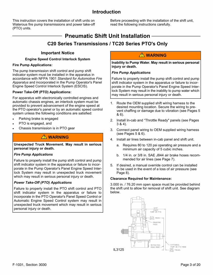
Clearance Required for Maintenance:
3.000 in. / 76.20 mm open space must be provided behindthe shift unit to allow for removal of shift unit. See diagrambelow.
IL3125
Page 4 of 20F-1031, Section 3030
Pneumatic Shift
Panel Plate Dimensions and Panel Cut-outs
In-Cab Panel
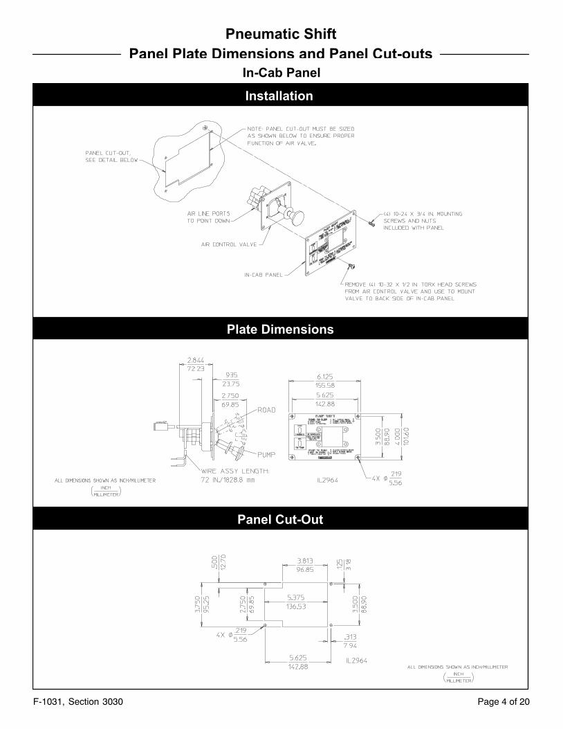
Installation
Plate Dimensions
Panel Cut-Out
Page 5 of 20F-1031, Section 3030
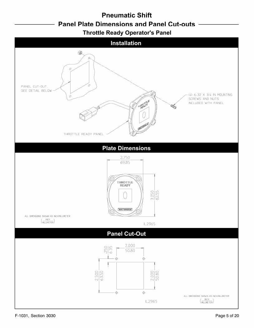
Pneumatic Shift
Panel Plate Dimensions and Panel Cut-outs
Throttle Ready Operator's Panel
Installation
Plate Dimensions
Panel Cut-Out
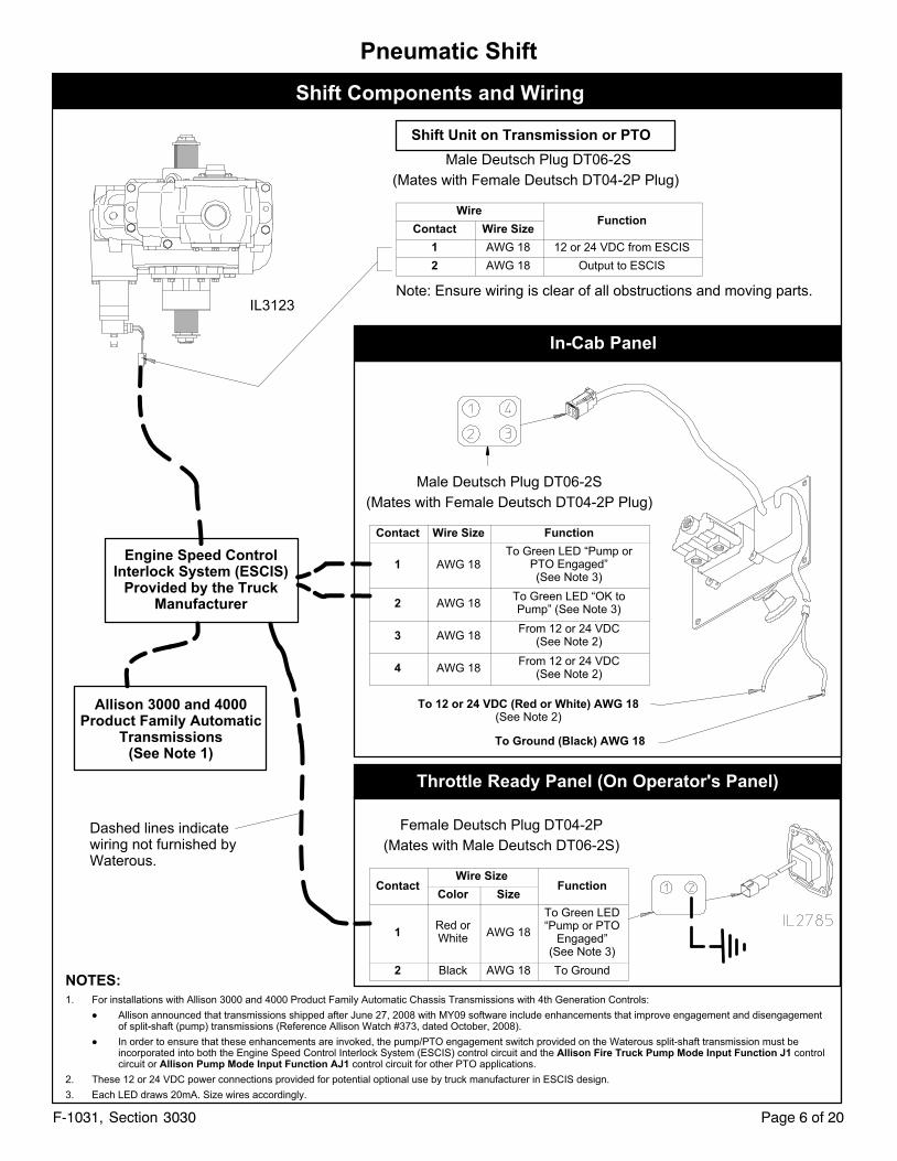
Shift Components and Wiring
Shift Unit on Transmission or PTO
In-Cab Panel
To 12 or 24 VDC (Red or White) AWG 18(See Note 2)
To Ground (Black) AWG 18
Throttle Ready Panel (On Operator's Panel)
Engine Speed ControlInterlock System (ESCIS)
Provided by the TruckManufacturer
Allison 3000 and 4000Product Family Automatic
Transmissions(See Note 1)
Dashed lines indicatewiring not furnished byWaterous.
NOTES:
1. For installations with Allison 3000 and 4000 Product Family Automatic Chassis Transmissions with 4th Generation Controls:
� Allison announced that transmissions shipped after June 27, 2008 with MY09 software include enhancements that improve engagement and disengagementof split-shaft (pump) transmissions (Reference Allison Watch #373, dated October, 2008).
� In order to ensure that these enhancements are invoked, the pump/PTO engagement switch provided on the Waterous split-shaft transmission must beincorporated into both the Engine Speed Control Interlock System (ESCIS) control circuit and the Allison Fire Truck Pump Mode Input Function J1 controlcircuit or Allison Pump Mode Input Function AJ1 control circuit for other PTO applications.
2. These 12 or 24 VDC power connections provided for potential optional use by truck manufacturer in ESCIS design.
3. Each LED draws 20mA. Size wires accordingly.
IL3123
Page 6 of 20F-1031, Section 3030
Pneumatic Shift
Male Deutsch Plug DT06-2S
(Mates with Female Deutsch DT04-2P Plug)
WireFunction
Contact Wire Size
1 AWG 18 12 or 24 VDC from ESCIS
2 AWG 18 Output to ESCIS
Note: Ensure wiring is clear of all obstructions and moving parts.
Male Deutsch Plug DT06-2S
(Mates with Female Deutsch DT04-2P Plug)
Contact Wire Size Function
1 AWG 18To Green LED “Pump or
PTO Engaged”(See Note 3)
2 AWG 18To Green LED “OK toPump” (See Note 3)
3 AWG 18From 12 or 24 VDC
(See Note 2)
4 AWG 18From 12 or 24 VDC
(See Note 2)
Female Deutsch Plug DT04-2P
(Mates with Male Deutsch DT06-2S)
ContactWire Size
FunctionColor Size
1Red orWhite
AWG 18
To Green LED“Pump or PTO
Engaged”(See Note 3)
2 Black AWG 18 To Ground
Page 7 of 20F-1031, Section 3030
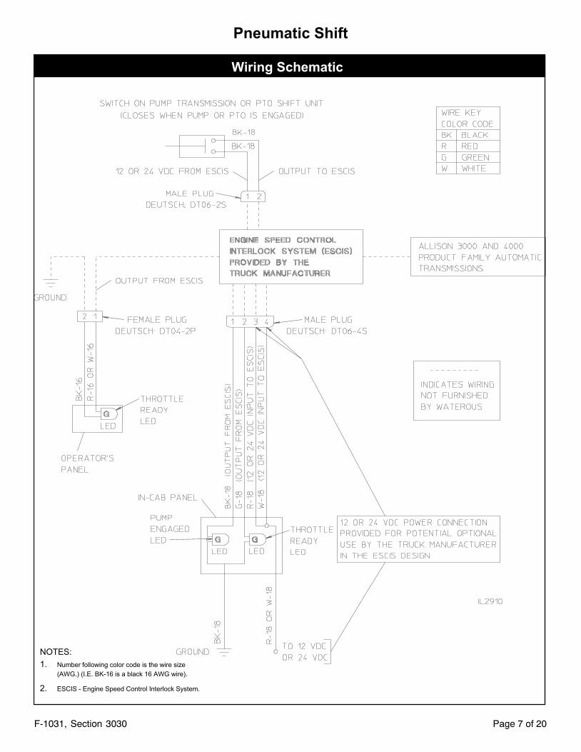
Pneumatic Shift
Wiring Schematic
NOTES:
1. Number following color code is the wire size
(AWG.) (I.E. BK-16 is a black 16 AWG wire).
2. ESCIS - Engine Speed Control Interlock System.
Page 8 of 20F-1031, Section 3030
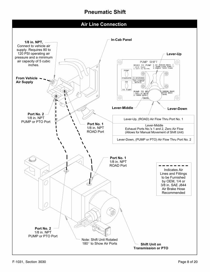
Pneumatic Shift
Air Line Connection
Lever-Up
Lever-Middle Lever-Down
Lever-Up, (ROAD) Air Flow Thru Port No. 1
Lever-MiddleExhaust Ports No.'s 1 and 2, Zero Air Flow(Allows for Manual Movement of Shift Unit)
Lever-Down, (PUMP or PTO) Air Flow Thru Port No. 2
Indicates AirLines and Fittingsto be Furnishedby OEM, 1/4 or
3/8 in. SAE J844Air Brake HoseRecommended
In-Cab Panel1/8 in. NPT,
Connect to vehicle airsupply. Requires 80 to120 PSI operating air
pressure and a minimumair capacity of 5 cubic
inches.
From VehicleAir Supply
Port No. 21/8 in. NPT
PUMP or PTO Port
Port No. 21/8 in. NPT
PUMP or PTO Port
Port No. 11/8 in. NPTROAD Port
Shift Unit onTransmission or PTO
Port No. 11/8 in. NPTROAD Port
Note: Shift Unit Rotated180� to Show Air Ports
Page 9 of 20F-1031, Section 3030
Pneumatic Shift
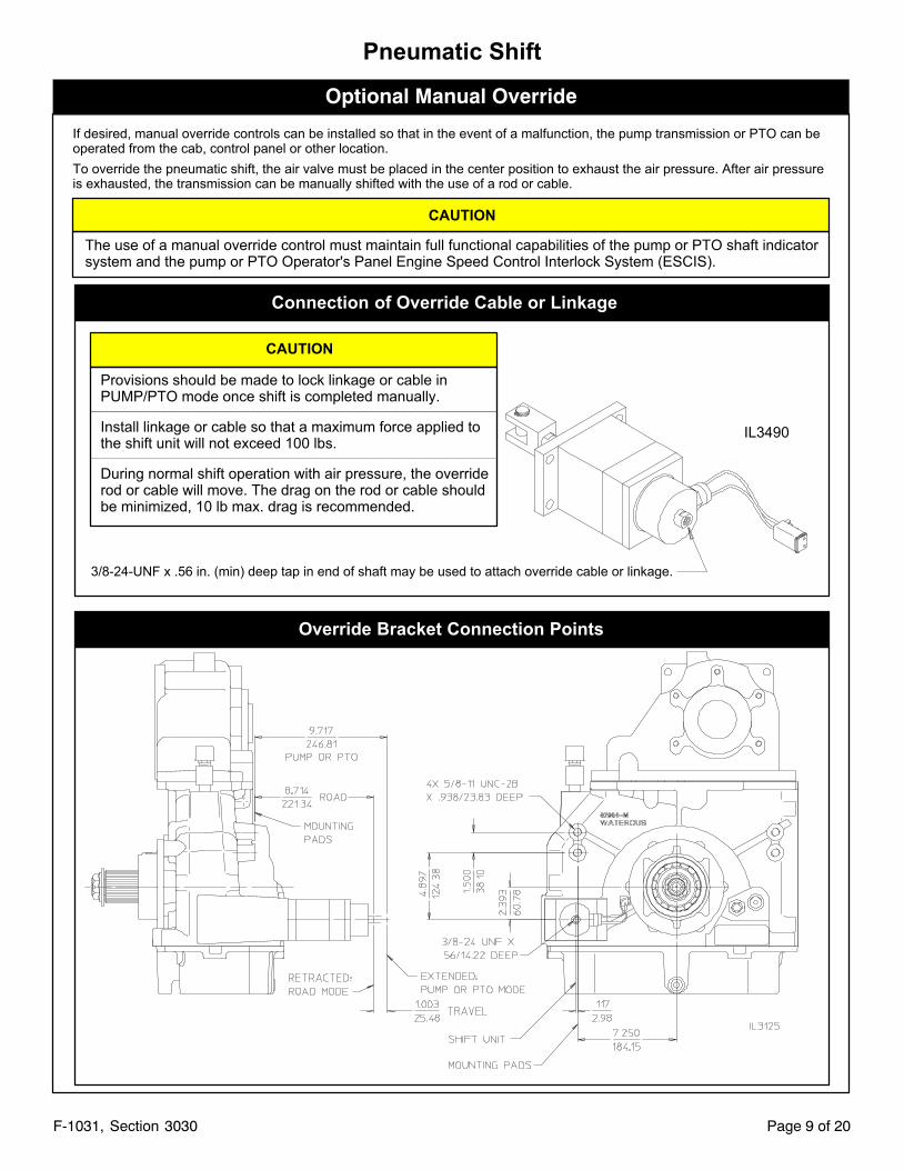
Optional Manual Override
3/8-24-UNF x .56 in. (min) deep tap in end of shaft may be used to attach override cable or linkage.
If desired, manual override controls can be installed so that in the event of a malfunction, the pump transmission or PTO can beoperated from the cab, control panel or other location.
To override the pneumatic shift, the air valve must be placed in the center position to exhaust the air pressure. After air pressureis exhausted, the transmission can be manually shifted with the use of a rod or cable.
CAUTION
The use of a manual override control must maintain full functional capabilities of the pump or PTO shaft indicatorsystem and the pump or PTO Operator's Panel Engine Speed Control Interlock System (ESCIS).
Connection of Override Cable or Linkage
CAUTION
Provisions should be made to lock linkage or cable inPUMP/PTO mode once shift is completed manually.
Install linkage or cable so that a maximum force applied tothe shift unit will not exceed 100 lbs.
During normal shift operation with air pressure, the overriderod or cable will move. The drag on the rod or cable shouldbe minimized, 10 lb max. drag is recommended.
Override Bracket Connection Points
IL3490
Page 10 of 20F-1031, Section 3030
Pneumatic Shift
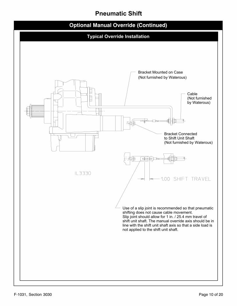
Optional Manual Override (Continued)
Typical Override Installation
Bracket Mounted on Case
(Not furnished by Waterous)
Cable(Not furnishedby Waterous)
Bracket Connectedto Shift Unit Shaft(Not furnished by Waterous)
Use of a slip joint is recommended so that pneumaticshifting does not cause cable movement.Slip joint should allow for 1 in. / 25.4 mm travel ofshift unit shaft. The manual override axis should be inline with the shift unit shaft axis so that a side load isnot applied to the shift unit shaft.
Page 11 of 20F-1031, Section 3030
Electric Shift Unit Installation
WB Series Transmissions and TML, TMR Series PTO's Only
Important Notice
Engine Speed Control Interlock System
Fire Pump Applications:
The pump transmission shift control and pump shiftindicator system must be installed in the apparatus inaccordance with NFPA 1901 Standard for Automotive FireApparatus and incorporated in the Pump Operator's PanelEngine Speed Control Interlock System (ESCIS).
Power Take-Off (PTO) Applications:
For apparatus with electronically controlled engines andautomatic chassis engines, an interlock system must beprovided to prevent advancement of the engine speed atthe PTO operator's panel or by an automatic speed controlsystem unless the following conditions are satisfied:
� Parking brake is engaged
� PTO is engaged, and
� Chassis transmission is in PTO gear
WARNING!
Unexpected Truck Movement. May result in seriouspersonal injury or death.
Fire Pump Applications
Failure to properly install the pump shift control and pumpshift indicator system in the apparatus or failure to incorporate in the Pump Operator's Panel Engine Speed Interlock System may result in unexpected truck movementwhich may result in serious personal injury or death.
Power Take-Off (PTO) Applications
Failure to properly install the PTO shift control and PTOshift indicator system in the apparatus or failure toincorporate in the PTO Operator's Panel Speed Control orAutomatic Engine Speed Control system may result inunexpected truck movement which may result in seriouspersonal injury or death.
WARNING!
Inability to Pump Water. May result in serious personalinjury or death.
Fire Pump Applications
Failure to properly install the pump shift control and pumpshift indicator system in the apparatus or failure to incorporate in the Pump Operator's Panel Engine Speed Interlock System may result in the inability to pump water whichmay result in serious personal injury or death.
1. Route the shift wiring harness to the desired mountinglocation. Secure the wiring to prevent chaffing or damage due to vibration (see Pages 13 & 14).
2. Install In-Cab Panel and Throttle Ready Panel (seePage 10).
3. If desired, a manual override control can be installedto be used in the event of a malfunction, the pumptransmission can be operated from the cab, controlpanel or other location (see Page 15).
Page 12 of 20F-1031, Section 3030
Electric Shift
Panel Plate Dimensions and Panel Cut-outs
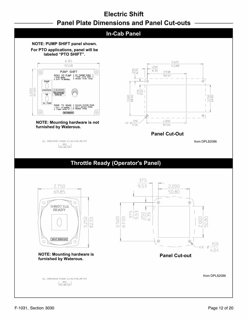
In-Cab Panel
Throttle Ready (Operator's Panel)
Panel Cut-outNOTE: Mounting hardware isfurnished by Waterous.
NOTE: Mounting hardware is notfurnished by Waterous.
Panel Cut-Out
from DPL82086
from DPL82086
NOTE: PUMP SHIFT panel shown.
For PTO applications, panel will belabeled “PTO SHIFT”.
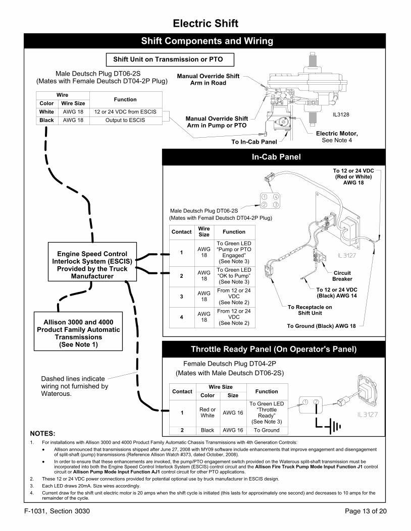
Shift Components and Wiring
Shift Unit on Transmission or PTO
In-Cab Panel
To 12 or 24 VDC(Black) AWG 14
To Ground (Black) AWG 18
Throttle Ready Panel (On Operator's Panel)
Engine Speed ControlInterlock System (ESCIS)
Provided by the TruckManufacturer
Allison 3000 and 4000Product Family Automatic
Transmissions(See Note 1)
Dashed lines indicatewiring not furnished byWaterous.
NOTES:
1. For installations with Allison 3000 and 4000 Product Family Automatic Chassis Transmissions with 4th Generation Controls:
� Allison announced that transmissions shipped after June 27, 2008 with MY09 software include enhancements that improve engagement and disengagementof split-shaft (pump) transmissions (Reference Allison Watch #373, dated October, 2008).
� In order to ensure that these enhancements are invoked, the pump/PTO engagement switch provided on the Waterous split-shaft transmission must beincorporated into both the Engine Speed Control Interlock System (ESCIS) control circuit and the Allison Fire Truck Pump Mode Input Function J1 controlcircuit or Allison Pump Mode Input Function AJ1 control circuit for other PTO applications.
2. These 12 or 24 VDC power connections provided for potential optional use by truck manufacturer in ESCIS design.
3. Each LED draws 20mA. Size wires accordingly.
4. Current draw for the shift unit electric motor is 20 amps when the shift cycle is initiated (this lasts for approximately one second) and decreases to 10 amps for theremainder of the cycle.
Manual Override ShiftArm in Road
Manual Override ShiftArm in Pump or PTO
Electric Motor,See Note 4To In-Cab Panel
IL3128
To Receptacle onShift Unit
CircuitBreaker
To 12 or 24 VDC(Red or White)
AWG 18
Male Deutsch Plug DT06-2S
(Mates with Femail Deutsch DT04-2P Plug)
Page 13 of 20F-1031, Section 3030
Electric Shift
Male Deutsch Plug DT06-2S(Mates with Female Deutsch DT04-2P Plug)
WireFunction
Color Wire Size
White AWG 18 12 or 24 VDC from ESCIS
Black AWG 18 Output to ESCIS
ContactWireSize
Function
1AWG
18
To Green LED“Pump or PTO
Engaged”(See Note 3)
2AWG
18
To Green LED“OK to Pump”(See Note 3)
3AWG
18
From 12 or 24VDC
(See Note 2)
4AWG
18
From 12 or 24VDC
(See Note 2)
Female Deutsch Plug DT04-2P
(Mates with Male Deutsch DT06-2S)
ContactWire Size
FunctionColor Size
1Red orWhite
AWG 16
To Green LED“ThrottleReady”
(See Note 3)
2 Black AWG 16 To Ground
Page 14 of 20F-1031, Section 3030
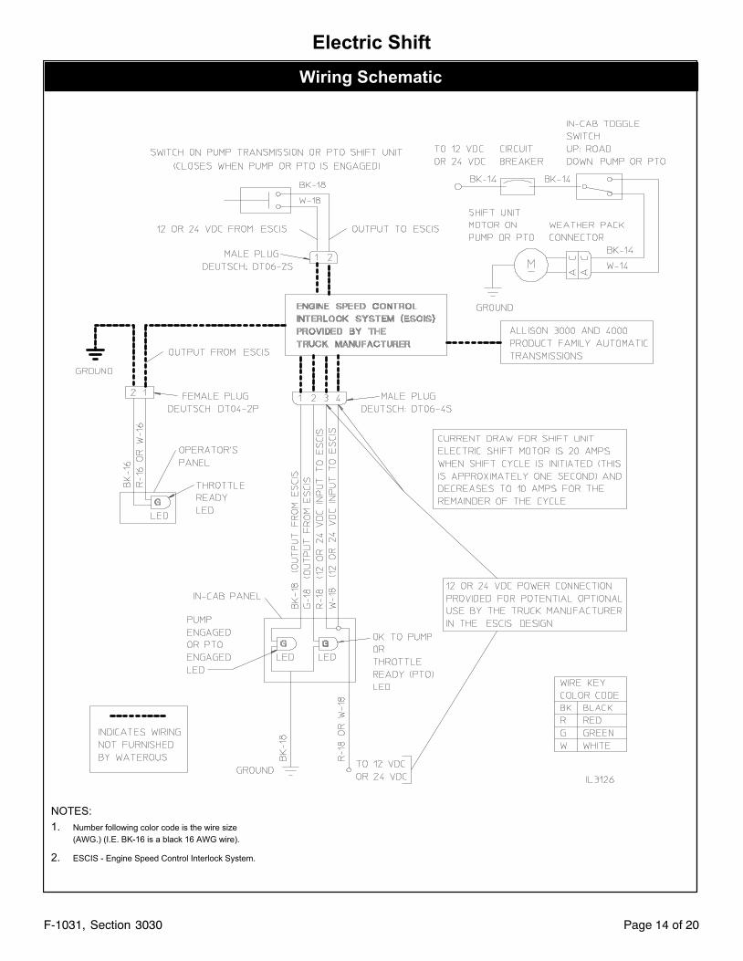
Electric Shift
Wiring Schematic
NOTES:
1. Number following color code is the wire size
(AWG.) (I.E. BK-16 is a black 16 AWG wire).
2. ESCIS - Engine Speed Control Interlock System.
Page 15 of 20F-1031, Section 3030
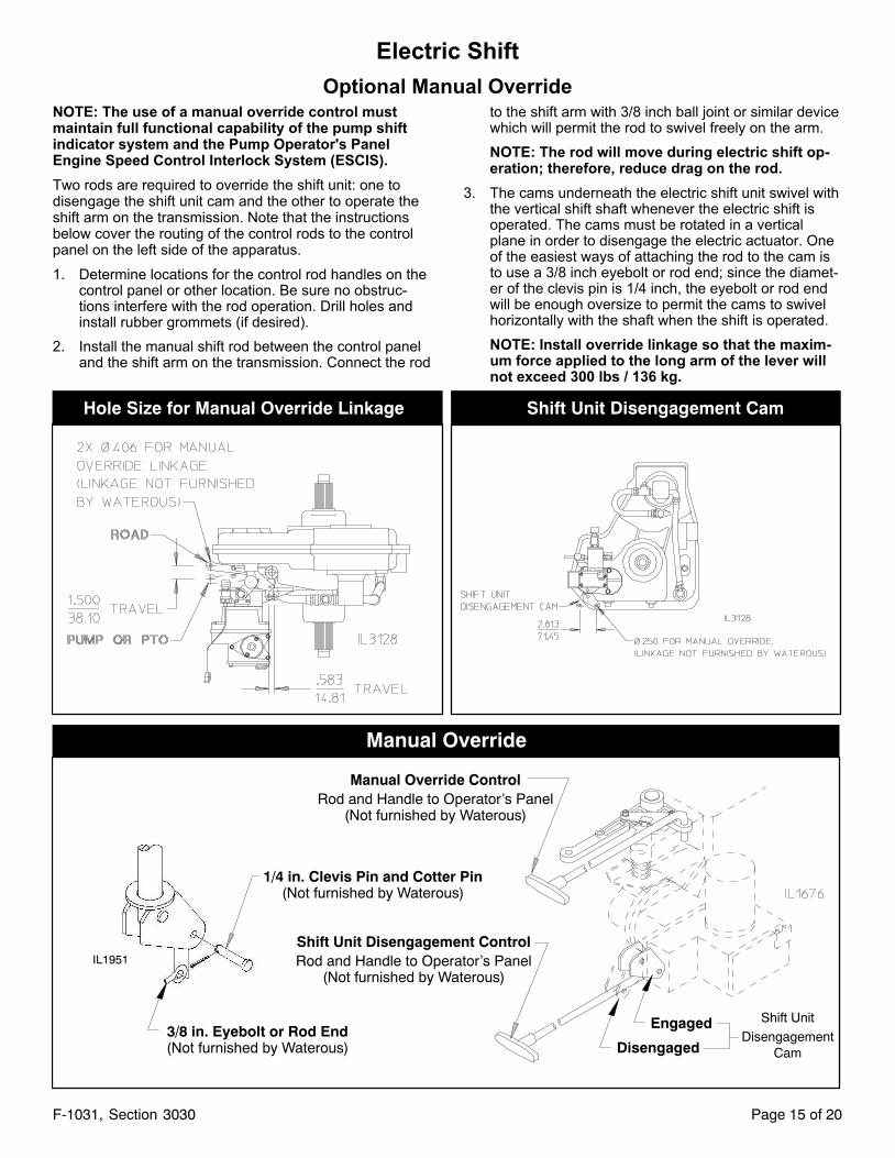
Electric Shift
Optional Manual OverrideNOTE: The use of a manual override control mustmaintain full functional capability of the pump shiftindicator system and the Pump Operator's PanelEngine Speed Control Interlock System (ESCIS).
Two rods are required to override the shift unit: one todisengage the shift unit cam and the other to operate theshift arm on the transmission. Note that the instructionsbelow cover the routing of the control rods to the controlpanel on the left side of the apparatus.
1. Determine locations for the control rod handles on thecontrol panel or other location. Be sure no obstructions interfere with the rod operation. Drill holes andinstall rubber grommets (if desired).
2. Install the manual shift rod between the control paneland the shift arm on the transmission. Connect the rod
to the shift arm with 3/8 inch ball joint or similar devicewhich will permit the rod to swivel freely on the arm.
NOTE: The rod will move during electric shift operation; therefore, reduce drag on the rod.
3. The cams underneath the electric shift unit swivel withthe vertical shift shaft whenever the electric shift isoperated. The cams must be rotated in a verticalplane in order to disengage the electric actuator. Oneof the easiest ways of attaching the rod to the cam isto use a 3/8 inch eyebolt or rod end; since the diameter of the clevis pin is 1/4 inch, the eyebolt or rod endwill be enough oversize to permit the cams to swivelhorizontally with the shaft when the shift is operated.
NOTE: Install override linkage so that the maximum force applied to the long arm of the lever willnot exceed 300 lbs / 136 kg.
Hole Size for Manual Override Linkage Shift Unit Disengagement Cam
Manual Override
1/4 in. Clevis Pin and Cotter Pin(Not furnished by Waterous)
3/8 in. Eyebolt or Rod End(Not furnished by Waterous)
Manual Override ControlRod and Handle to Operator's Panel
(Not furnished by Waterous)
Shift Unit Disengagement ControlRod and Handle to Operator's Panel
(Not furnished by Waterous)
Disengaged
Engaged Shift Unit
DisengagementCam
IL1951
Page 16 of 20F-1031, Section 3030
Manual Shift Unit Installation
WB Series Transmissions and TML, TMR Series PTO's Only
Important Notice
Engine Speed Control Interlock System
Fire Pump Applications:
The pump transmission shift control and pump shiftindicator system must be installed in the apparatus inaccordance with NFPA 1901 Standard for Automotive FireApparatus and incorporated in the Pump Operator's PanelEngine Speed Control Interlock System (ESCIS).
Power Take-Off (PTO) Applications:
For apparatus with electronically controlled engines andautomatic chassis engines, an interlock system must beprovided to prevent advancement of the engine speed atthe PTO operator's panel or by an automatic speed controlsystem unless the following conditions are satisfied:
� Parking brake is engaged
� PTO is engaged, and
� Chassis transmission is in PTO gear
WARNING!
Unexpected Truck Movement. May result in seriouspersonal injury or death.
Fire Pump Applications
Failure to properly install the pump shift control and pumpshift indicator system in the apparatus or failure to incorporate in the Pump Operator's Panel Engine Speed Interlock System may result in unexpected truck movementwhich may result in serious personal injury or death.
Power Take-Off (PTO) Applications
Failure to properly install the PTO shift control and PTOshift indicator system in the apparatus or failure toincorporate in the PTO Operator's Panel Speed Control orAutomatic Engine Speed Control system may result inunexpected truck movement which may result in seriouspersonal injury or death.
WARNING!
Inability to Pump Water. May result in serious personalinjury or death.
Fire Pump Applications
Failure to properly install the pump shift control and pumpshift indicator system in the apparatus or failure to incorporate in the Pump Operator's Panel Engine Speed Interlock System may result in the inability to pump water whichmay result in serious personal injury or death.
1. Install a suitable linkage which will permit operationfrom the cab, control panel or other location (see Page17).
a. Determine locations for the control rod handles onthe panel. Drill holes and install grommets (if desired). Ensure that no obstructions interfere with rodoperation.
b. Install shift linkage so that the maximum force applied to the long arm of the shift lever will not exceed300 lbs / 136 kg.
c. Connect the rod to the shift arm with a 3/8 in. balljoint or similar device which will permit the rod toswivel freely on the arm.
2. Route the shift wiring harness to the desired mountinglocation. Secure the wiring to prevent chaffing or damage due to vibration.
3. Install In-Cab and Throttle Ready panels (see Page16).
4. Connect panel wiring to OEM supplied wiring (seePage 19 and 20).
Page 17 of 20F-1031, Section 3030
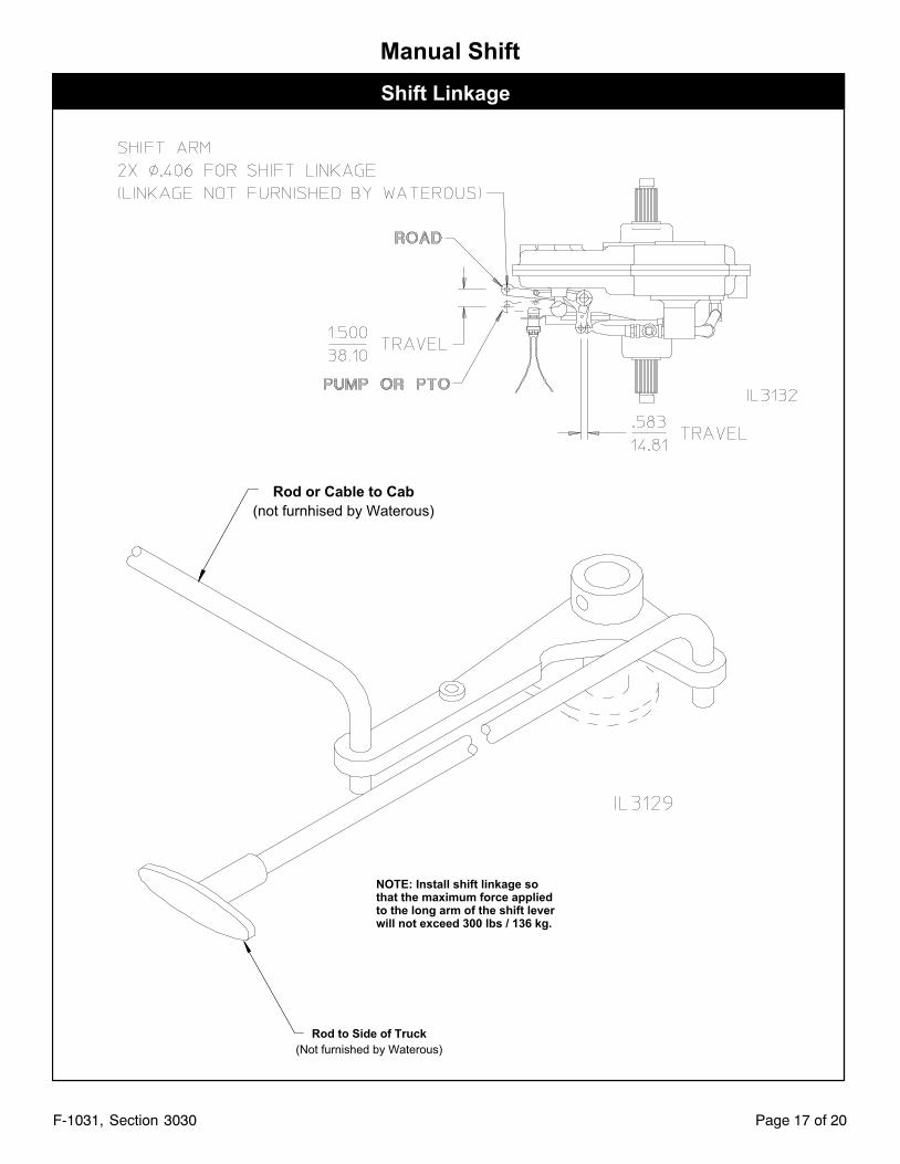
Manual Shift
Shift Linkage
Rod to Side of Truck
(Not furnished by Waterous)
NOTE: Install shift linkage sothat the maximum force appliedto the long arm of the shift leverwill not exceed 300 lbs / 136 kg.
Rod or Cable to Cab
(not furnhised by Waterous)
Page 18 of 20F-1031, Section 3030
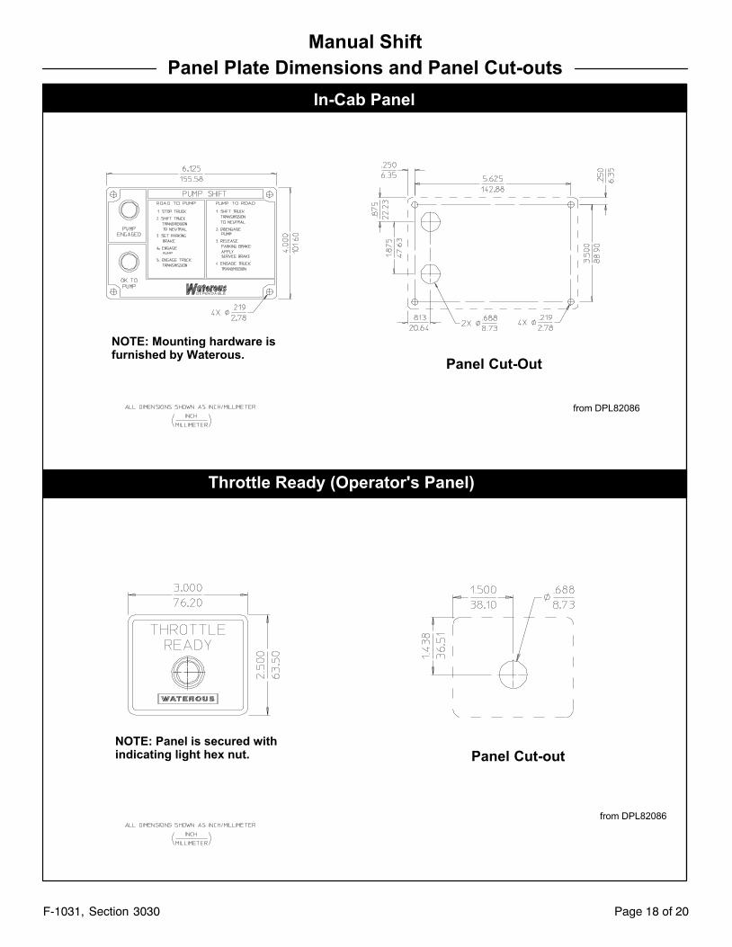
Manual Shift
Panel Plate Dimensions and Panel Cut-outs
In-Cab Panel
Throttle Ready (Operator's Panel)
Panel Cut-out
NOTE: Mounting hardware isfurnished by Waterous.
NOTE: Panel is secured withindicating light hex nut.
Panel Cut-Out
from DPL82086
from DPL82086
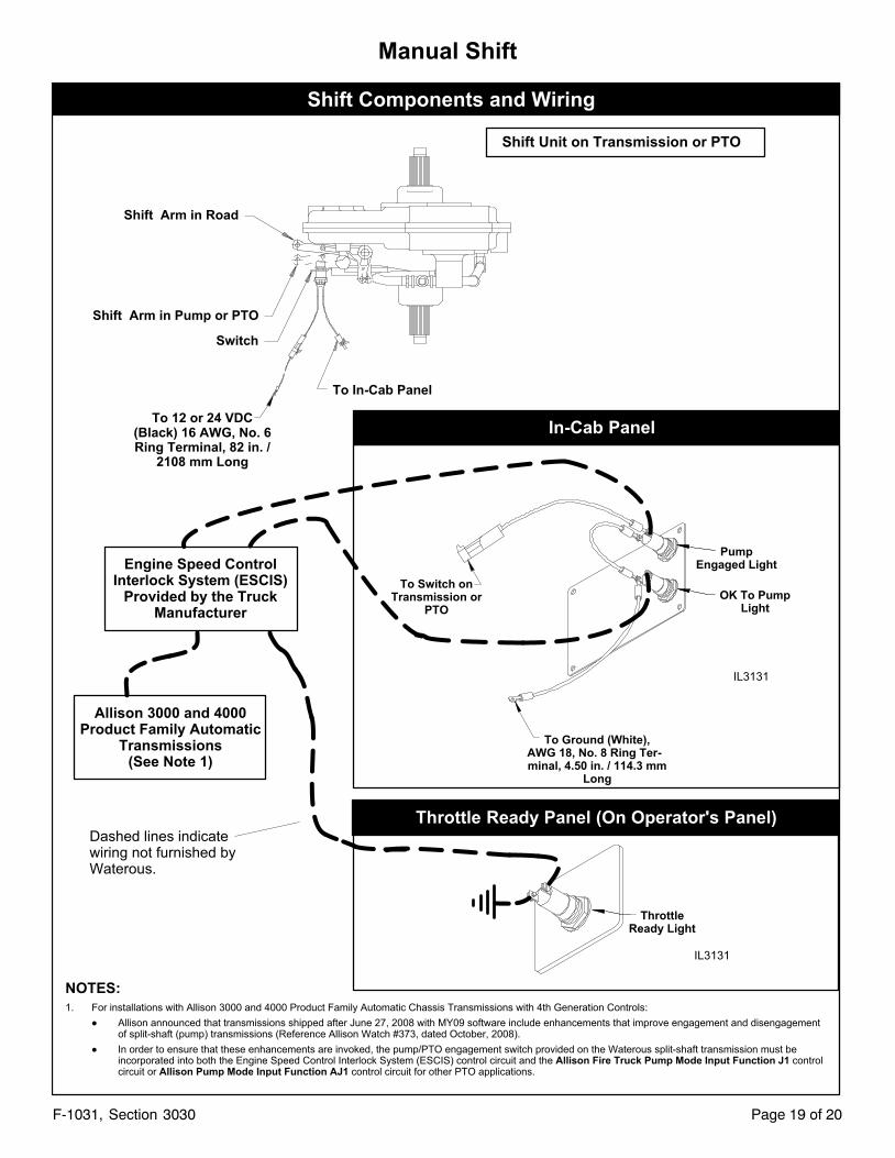
Shift Components and Wiring
Shift Unit on Transmission or PTO
In-Cab Panel
To Switch onTransmission or
PTO
Throttle Ready Panel (On Operator's Panel)
Engine Speed ControlInterlock System (ESCIS)
Provided by the TruckManufacturer
Allison 3000 and 4000Product Family Automatic
Transmissions(See Note 1)
Dashed lines indicatewiring not furnished byWaterous.
NOTES:
1. For installations with Allison 3000 and 4000 Product Family Automatic Chassis Transmissions with 4th Generation Controls:
� Allison announced that transmissions shipped after June 27, 2008 with MY09 software include enhancements that improve engagement and disengagementof split-shaft (pump) transmissions (Reference Allison Watch #373, dated October, 2008).
� In order to ensure that these enhancements are invoked, the pump/PTO engagement switch provided on the Waterous split-shaft transmission must beincorporated into both the Engine Speed Control Interlock System (ESCIS) control circuit and the Allison Fire Truck Pump Mode Input Function J1 controlcircuit or Allison Pump Mode Input Function AJ1 control circuit for other PTO applications.
Shift Arm in Road
Shift Arm in Pump or PTO
To 12 or 24 VDC(Black) 16 AWG, No. 6Ring Terminal, 82 in. /
2108 mm Long
To In-Cab Panel
To Ground (White),AWG 18, No. 8 Ring Terminal, 4.50 in. / 114.3 mm
Long
PumpEngaged Light
Switch
OK To PumpLight
ThrottleReady Light
IL3131
IL3131
Page 19 of 20F-1031, Section 3030
Manual Shift
Page 20 of 20F-1031, Section 3030
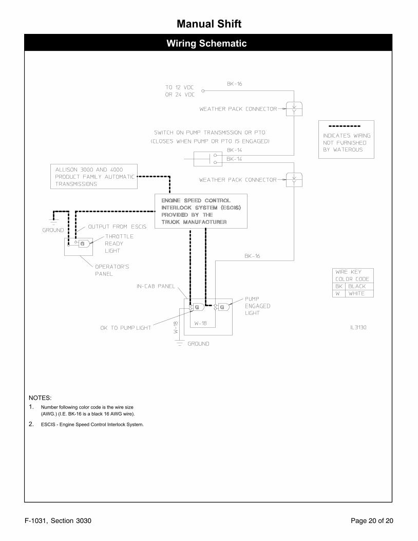
Manual Shift
Wiring Schematic
NOTES:
1. Number following color code is the wire size
(AWG.) (I.E. BK-16 is a black 16 AWG wire).
2. ESCIS - Engine Speed Control Interlock System.


![(52,911)...Allison 4th Generation Electronic Controls wittr closed loop adaptive shifu Shift Sequences [C = Converter mode (lockup clutch disengaged); L = [o*up (lockup clutch engaged)]](https://img.pdfslide.us/doc/110x75/611640d480377e06ac19f53b/52911-allison-4th-generation-electronic-controls-wittr-closed-loop-adaptive.jpg)