Embed Size (px)
Citation preview
1
Q'TY
1
1
1
1
1
2
1
2
2
1
1
10
4
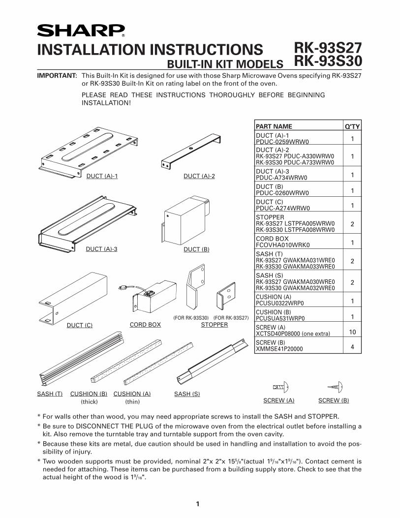
PART NAMEDUCT (A)-1PDUC-0259WRW0DUCT (A)-2RK-93S27 PDUC-A330WRW0RK-93S30 PDUC-A733WRW0DUCT (A)-3PDUC-A734WRW0DUCT (B)PDUC-0260WRW0DUCT (C)PDUC-A274WRW0STOPPERRK-93S27 LSTPFA005WRW0RK-93S30 LSTPFA008WRW0CORD BOXFCOVHA010WRK0SASH (T)RK-93S27 GWAKMA031WRE0RK-93S30 GWAKMA033WRE0SASH (S)RK-93S27 GWAKMA030WRE0RK-93S30 GWAKMA032WRE0CUSHION (A)PCUSU0322WRP0CUSHION (B)PCUSUA531WRP0SCREW (A)XCTSD40P08000 (one extra)SCREW (B)XMMSE41P20000
INSTALLATION INSTRUCTIONS BUILT-IN KIT MODELS IMPORTANT: This Built-In Kit is designed for use with those Sharp Microwave Ovens specifying RK-93S27
or RK-93S30 Built-In Kit on rating label on the front of the oven.
PLEASE READ THESE INSTRUCTIONS THOROUGHLY BEFORE BEGINNING INSTALLATION!
RK-93S27RK-93S30
* For walls other than wood, you may need appropriate screws to install the SASH and STOPPER.* Be sure to DISCONNECT THE PLUG of the microwave oven from the electrical outlet before installing a
kit. Also remove the turntable tray and turntable support from the oven cavity.* Because these kits are metal, due caution should be used in handling and installation to avoid the pos-
sibility of injury.* Two wooden supports must be provided, nominal 2"x 2"x 155/8"(actual 19/16"x19/16"). Contact cement is
needed for attaching. These items can be purchased from a building supply store. Check to see that the actual height of the wood is 19/16".
DUCT (A)-1 DUCT (A)-2
DUCT (A)-3 DUCT (B)
STOPPERCORD BOXDUCT (C)
SCREW (B)SCREW (A)SASH (T) CUSHION (B)
(thick)CUSHION (A)
(thin)SASH (S)
(FOR RK-93S27)(FOR RK-93S30)
2
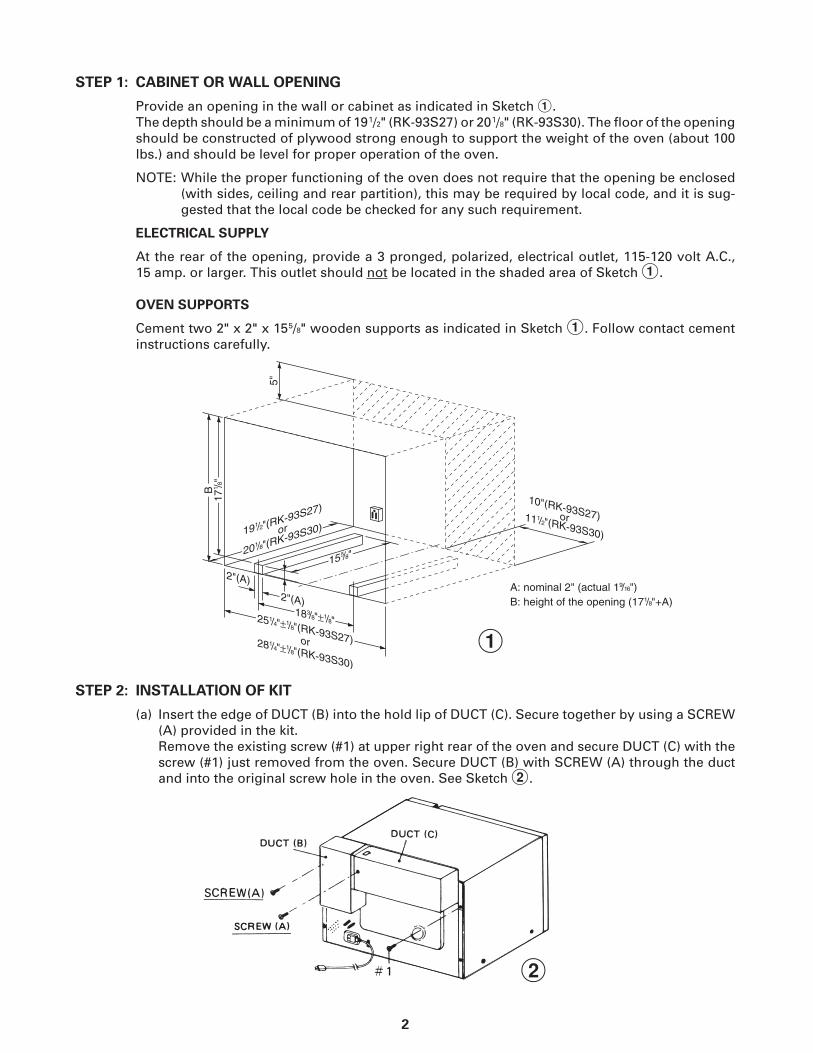
STEP 1: CABINET OR WALL OPENING
Provide an opening in the wall or cabinet as indicated in Sketch 1. The depth should be a minimum of 19 1/2" (RK-93S27) or 20 1/8" (RK-93S30). The floor of the opening
should be constructed of plywood strong enough to support the weight of the oven (about 100 lbs.) and should be level for proper operation of the oven.
NOTE: While the proper functioning of the oven does not require that the opening be enclosed (with sides, ceiling and rear partition), this may be required by local code, and it is sug-gested that the local code be checked for any such requirement.
ELECTRICAL SUPPLY
At the rear of the opening, provide a 3 pronged, polarized, electrical outlet, 115-120 volt A.C., 15 amp. or larger. This outlet should not be located in the shaded area of Sketch 1.
OVEN SUPPORTS
Cement two 2" x 2" x 15 5/8" wooden supports as indicated in Sketch 1. Follow contact cement instructions carefully.
STEP 2: INSTALLATION OF KIT
(a) Insert the edge of DUCT (B) into the hold lip of DUCT (C). Secure together by using a SCREW (A) provided in the kit.
Remove the existing screw (#1) at upper right rear of the oven and secure DUCT (C) with the screw (#1) just removed from the oven. Secure DUCT (B) with SCREW (A) through the duct and into the original screw hole in the oven. See Sketch 2.
1
2
3
CUSHION (A)
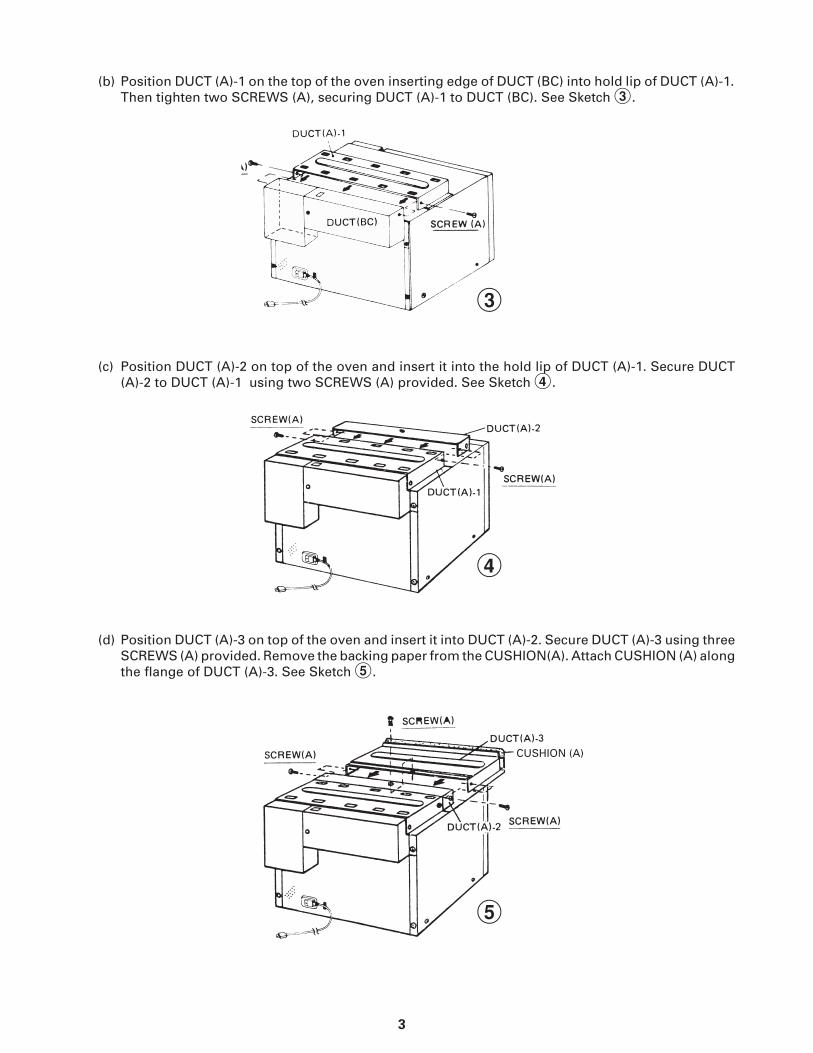
(b) Position DUCT (A)-1 on the top of the oven inserting edge of DUCT (BC) into hold lip of DUCT (A)-1. Then tighten two SCREWS (A), securing DUCT (A)-1 to DUCT (BC). See Sketch 3.
(d) Position DUCT (A)-3 on top of the oven and insert it into DUCT (A)-2. Secure DUCT (A)-3 using three SCREWS (A) provided. Remove the backing paper from the CUSHION(A). Attach CUSHION (A) along the flange of DUCT (A)-3. See Sketch 5.
3
4
5
(c) Position DUCT (A)-2 on top of the oven and insert it into the hold lip of DUCT (A)-1. Secure DUCT (A)-2 to DUCT (A)-1 using two SCREWS (A) provided. See Sketch 4.
BOTTOM PLATE
CUSHION (B)
SCREWS
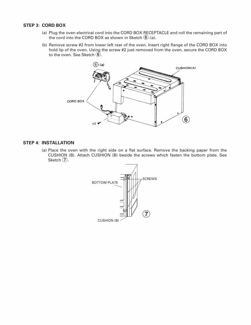
STEP 4: INSTALLATION
(a) Place the oven with the right side on a flat surface. Remove the backing paper from the CUSHION (B). Attach CUSHION (B) beside the screws which fasten the bottom plate. See Sketch 7.
7
STEP 3: CORD BOX
(a) Plug the oven electrical cord into the CORD BOX RECEPTACLE and roll the remaining part of the cord into the CORD BOX as shown in Sketch 6-(a).
(b) Remove screw #2 from lower left rear of the oven. Insert right flange of the CORD BOX into hold lip of the oven. Using the screw #2 just removed from the oven, secure the CORD BOX to the oven. See Sketch 6.
6
5
STOPPER(RK-93S27)
#3
#4
#4
STOPPER(RK-93S27)
STOPPER(RK-93S30)
STOPPER(RK-93S30)
#3
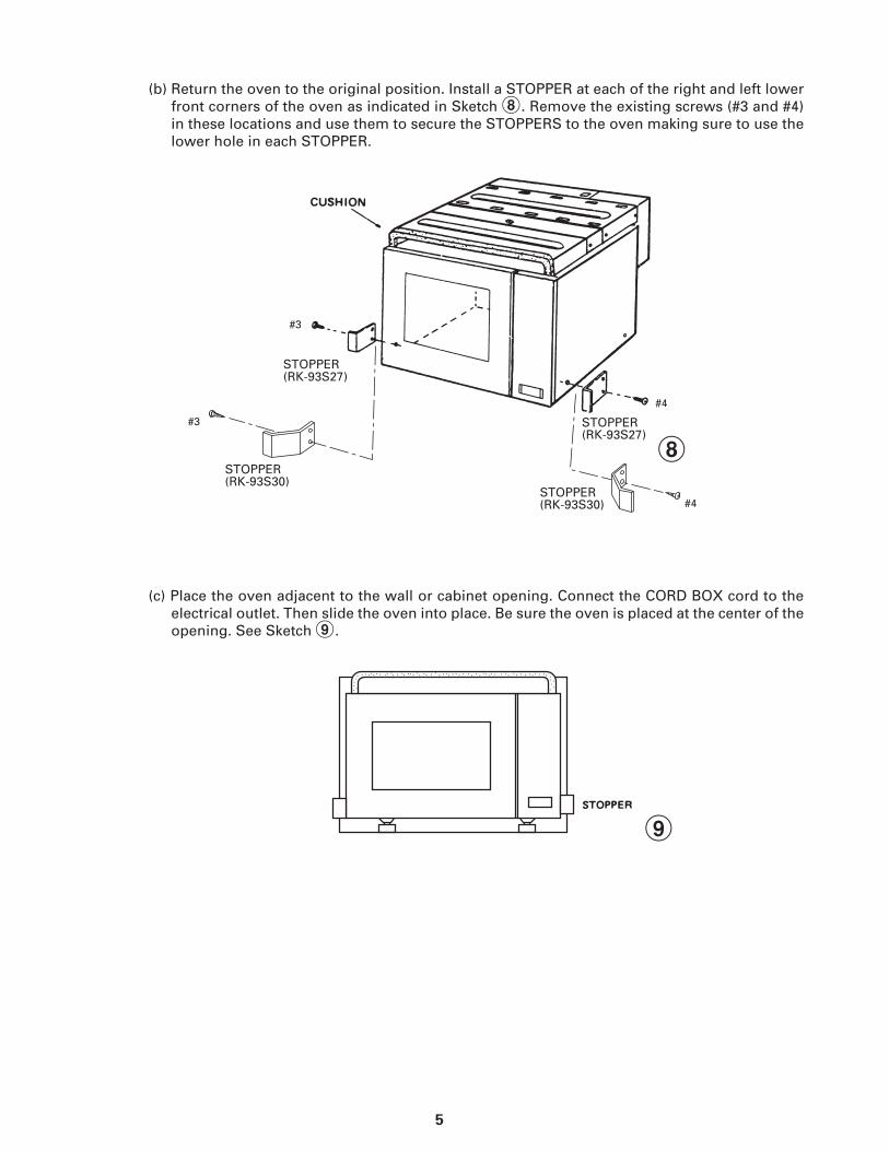
(c) Place the oven adjacent to the wall or cabinet opening. Connect the CORD BOX cord to the electrical outlet. Then slide the oven into place. Be sure the oven is placed at the center of the opening. See Sketch 9.
8
(b) Return the oven to the original position. Install a STOPPER at each of the right and left lower front corners of the oven as indicated in Sketch 8. Remove the existing screws (#3 and #4) in these locations and use them to secure the STOPPERS to the oven making sure to use the lower hole in each STOPPER.
9
6
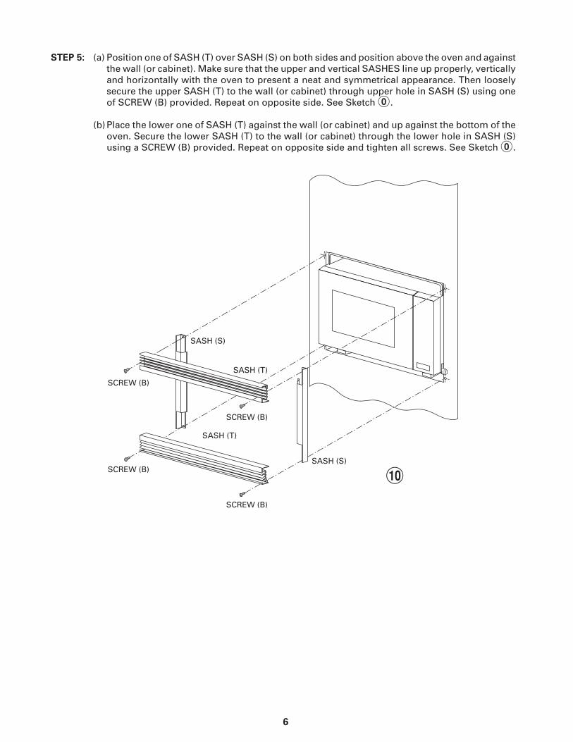
STEP 5: (a) Position one of SASH (T) over SASH (S) on both sides and position above the oven and against the wall (or cabinet). Make sure that the upper and vertical SASHES line up properly, vertically and horizontally with the oven to present a neat and symmetrical appearance. Then loosely secure the upper SASH (T) to the wall (or cabinet) through upper hole in SASH (S) using one of SCREW (B) provided. Repeat on opposite side. See Sketch 0.
(b) Place the lower one of SASH (T) against the wall (or cabinet) and up against the bottom of the
oven. Secure the lower SASH (T) to the wall (or cabinet) through the lower hole in SASH (S) using a SCREW (B) provided. Repeat on opposite side and tighten all screws. See Sketch 0.
!


8
SHARP ELECTRONICS CORPORATIONSharp Plaza, Mahwah, New Jersey 07495-1163Phone: 1-800-BE-SHARP (237-4277) TINSEB348WRRZ