Embed Size (px)
Citation preview
Water heater unit
Supplementary heating Thermo Top C
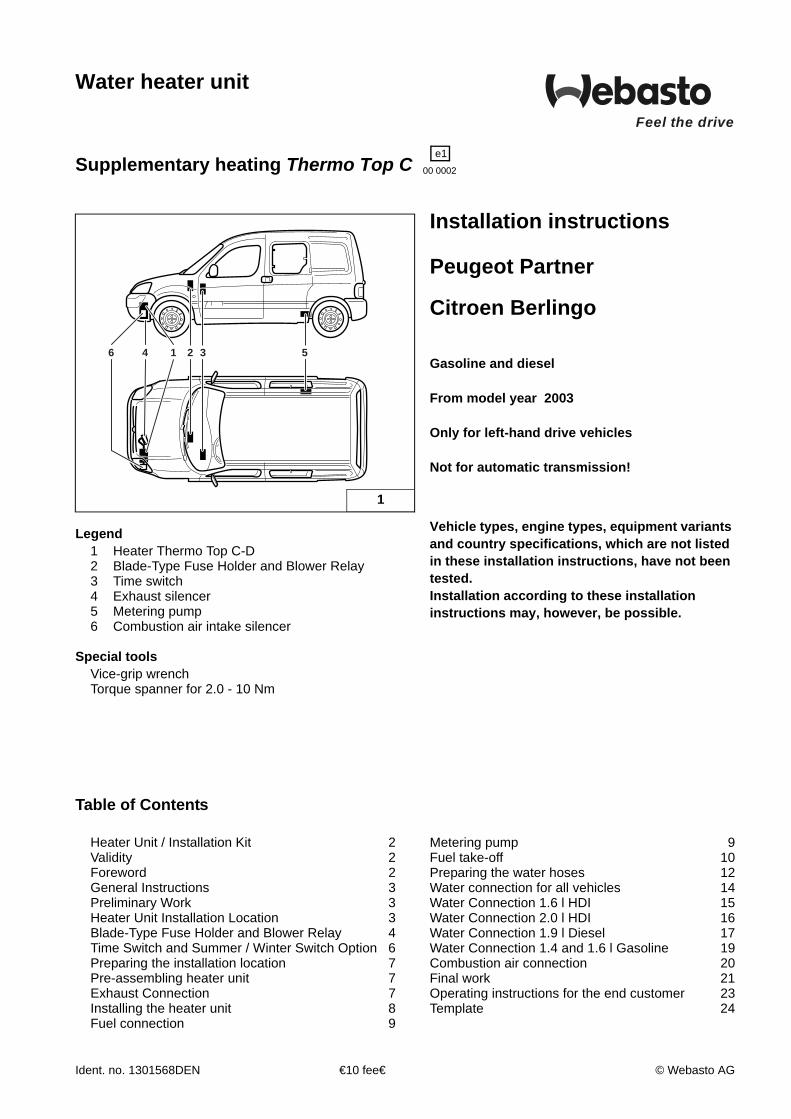
Legend1 Heater Thermo Top C-D2 Blade-Type Fuse Holder and Blower Relay3 Time switch4 Exhaust silencer5 Metering pump6 Combustion air intake silencer
Special toolsVice-grip wrenchTorque spanner for 2.0 - 10 Nm
Table of Contents
CI 0049 W
3 52146
1
Installation instructions
Peugeot Partner
Citroen Berlingo
Gasoline and diesel
From model year 2003
Only for left-hand drive vehicles
Not for automatic transmission!
Vehicle types, engine types, equipment variants and country specifications, which are not listed in these installation instructions, have not been tested.Installation according to these installation instructions may, however, be possible.
Heater Unit / Installation Kit 2Validity 2Foreword 2General Instructions 3Preliminary Work 3Heater Unit Installation Location 3Blade-Type Fuse Holder and Blower Relay 4Time Switch and Summer / Winter Switch Option 6Preparing the installation location 7Pre-assembling heater unit 7Exhaust Connection 7Installing the heater unit 8Fuel connection 9
Metering pump 9Fuel take-off 10Preparing the water hoses 12Water connection for all vehicles 14Water Connection 1.6 l HDI 15Water Connection 2.0 l HDI 16Water Connection 1.9 l Diesel 17Water Connection 1.4 and 1.6 l Gasoline 19Combustion air connection 20Final work 21Operating instructions for the end customer 23Template 24
e100 0002
Feel the drive
Ident. no. 1301568DEN €10 fee€ © Webasto AG
Thermo Top C Peugeot Partner / Citroen Berlingo
Heater unit / Installation kit
Quantity Name Order No.
1 Water heater unit Thermo Top C-B with scope of delivery 906 04Dor
1 Water heater unit Thermo Top C-D with scope of delivery 892 44D
Also required:
1 Installation kit for Peugeot Partner / Citroen Berlingo 1301565A
Validity
L
ForewordThese installation instructions apply to Peugeot Partner and Citroen Berlingo vehicles with diesel andgasoline engines – re. validity, see title page – from model year 2003 and later, assuming technicalmodifications to the vehicle do not affect installation, any liability claims excluded. Depending on the vehicle version and equipment, modifications may be necessary during installationwith respect to these installation instructions. However, the stipulations in the "installation instructions" and "operating and maintenanceinstructions" for the Thermo Top C/E are to be observed in any event. The corresponding rules of technology and any information from the vehicle manufacturer should beobserved during the installation work.
Manufacturer Model Type EG-BE No. / ABEPeugeot Partner M49 e2*2001/116*0279*00Peugeot Partner M49 L 083Peugeot Partner M49 e2*2001/116*0282*00Peugeot Partner G e2*2001/116*0322*00Citroen Berlingo M49 e2*2001/116*0276*00
Engine type Engine model Power in kW Engine capacity in cm³KFW Petrol 55 1360NFU Petrol 80 15879HX Diesel 66 1560WJY Diesel 51 1867RHY Diesel 66 1997
2
Peugeot Partner / Citroen Berlingo Thermo Top C
2
General instructions
- Cover unfinished body areas, such as bore holes,with corrosion protection
- Secure hoses, wires, and cable harnesses withcable clips and cover with protective hoses atfriction locations
- Fit sharp edges with edge protection (split openplastic hose)
Preliminary work
Engine Compartment
CAUTIONDisconnect the battery.Let off pressure in the cooling system.
- Remove the air filter housing- Copy the factory number from the original type label
to the duplicate type label- Remove years that do not apply from the duplicate
label- Attach the duplicate label (type label) in the
appropriate place
Vehicle Exterior- Open the tank cap, ventilate the tank- Close the tank cap again- Remove the front bumper- Remove front right wheel-house panel- Remove the front left wheel-house panel- Lower the tank (only for gasoline vehicles)
Vehicle Passenger Compartment- Remove the lower dashboard panel on the
passenger side
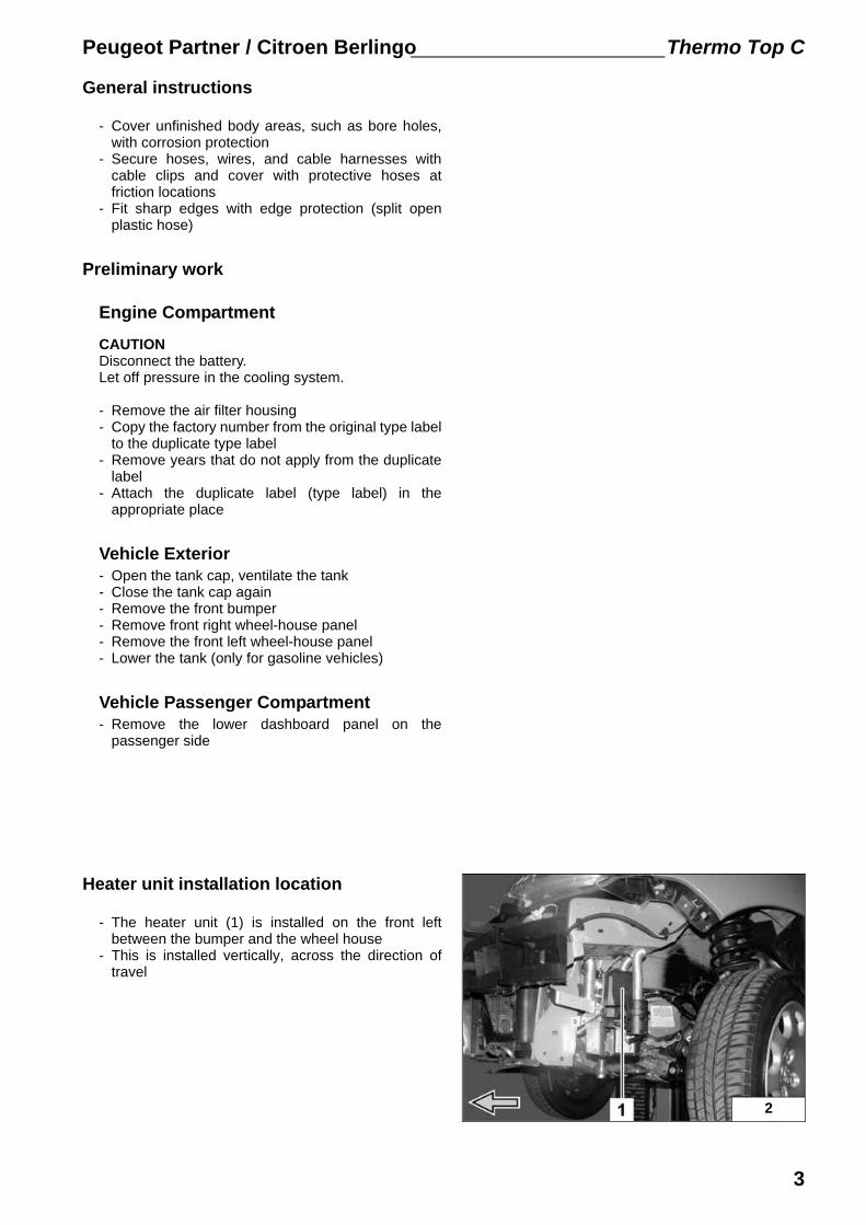
Heater unit installation location
- The heater unit (1) is installed on the front leftbetween the bumper and the wheel house
- This is installed vertically, across the direction oftravel
3
Thermo Top C Peugeot Partner / Citroen Berlingo
3
4
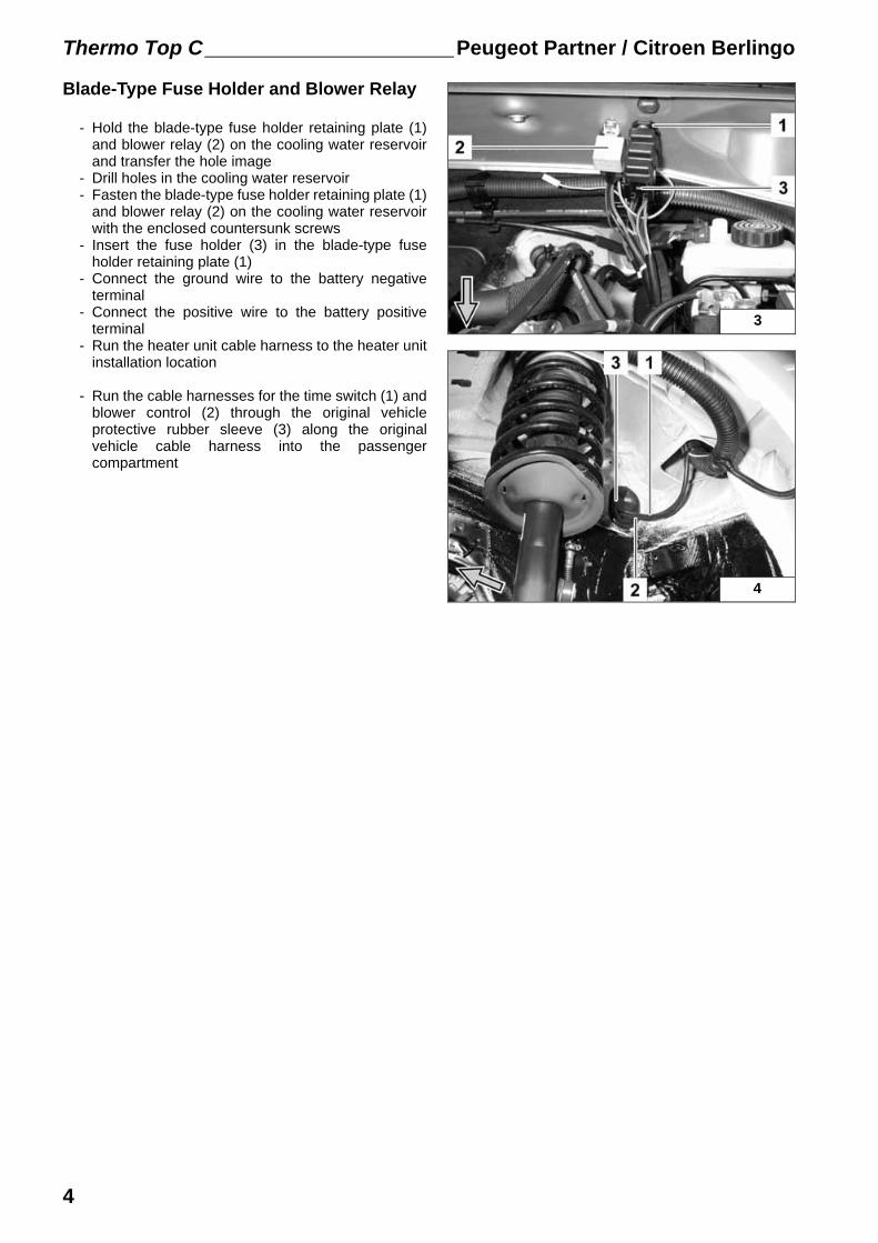
Blade-Type Fuse Holder and Blower Relay
- Hold the blade-type fuse holder retaining plate (1)and blower relay (2) on the cooling water reservoirand transfer the hole image
- Drill holes in the cooling water reservoir- Fasten the blade-type fuse holder retaining plate (1)
and blower relay (2) on the cooling water reservoirwith the enclosed countersunk screws
- Insert the fuse holder (3) in the blade-type fuseholder retaining plate (1)
- Connect the ground wire to the battery negativeterminal
- Connect the positive wire to the battery positiveterminal
- Run the heater unit cable harness to the heater unitinstallation location
- Run the cable harnesses for the time switch (1) andblower control (2) through the original vehicleprotective rubber sleeve (3) along the originalvehicle cable harness into the passengercompartment
4
Peugeot Partner / Citroen Berlingo Thermo Top C
M
X
F3
rtrtgn/ws
SG 1570
A2
A1
K386 87 87a
85 30
sw
br
3015
31
rt 4,0 mm†
rt 4,0 mm†
CI 0051 W
6
5
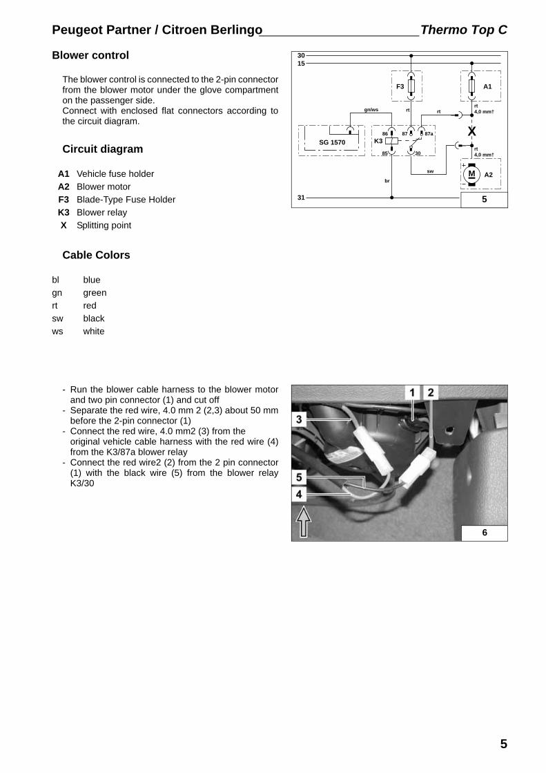
Blower control
The blower control is connected to the 2-pin connectorfrom the blower motor under the glove compartmenton the passenger side.Connect with enclosed flat connectors according tothe circuit diagram.
Circuit diagram
Cable Colors
- Run the blower cable harness to the blower motorand two pin connector (1) and cut off
- Separate the red wire, 4.0 mm 2 (2,3) about 50 mmbefore the 2-pin connector (1)
- Connect the red wire, 4.0 mm2 (3) from the original vehicle cable harness with the red wire (4)from the K3/87a blower relay
- Connect the red wire2 (2) from the 2 pin connector(1) with the black wire (5) from the blower relayK3/30
A1 Vehicle fuse holderA2 Blower motorF3 Blade-Type Fuse HolderK3 Blower relayX Splitting point
bl bluegn greenrt redsw blackws white
5
Thermo Top C Peugeot Partner / Citroen Berlingo
7
CI 0056 W8
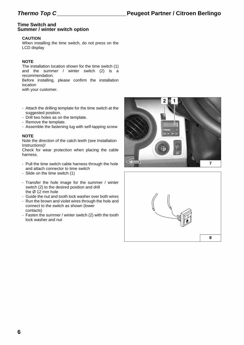
Time Switch andSummer / winter switch option
CAUTIONWhen installing the time switch, do not press on theLCD display
NOTEThe installation location shown for the time switch (1)and the summer / winter switch (2) is arecommendation.Before installing, please confirm the installationlocation with your customer.
- Attach the drilling template for the time switch at thesuggested position.
- Drill two holes as on the template.- Remove the template.- Assemble the fastening lug with self-tapping screw
NOTENote the direction of the catch teeth (see Installation Instructions)!Check for wear protection when placing the cableharness.
- Pull the time switch cable harness through the holeand attach connector to time switch
- Slide on the time switch (1)
- Transfer the hole image for the summer / winterswitch (2) to the desired position and drillthe Ø 12 mm hole
- Guide the nut and tooth lock washer over both wires- Run the brown and violet wires through the hole and
connect to the switch as shown (lowercontacts)
- Fasten the summer / winter switch (2) with the toothlock washer and nut
6
Peugeot Partner / Citroen Berlingo Thermo Top C
75350
1 32
CI 0052 W11
10
9
12
Preparing the Installation Location
- Cut off the 100 mm edge protection to 80 mm andinsert at position 1
- Insert the 200 mm edge protection at position 2
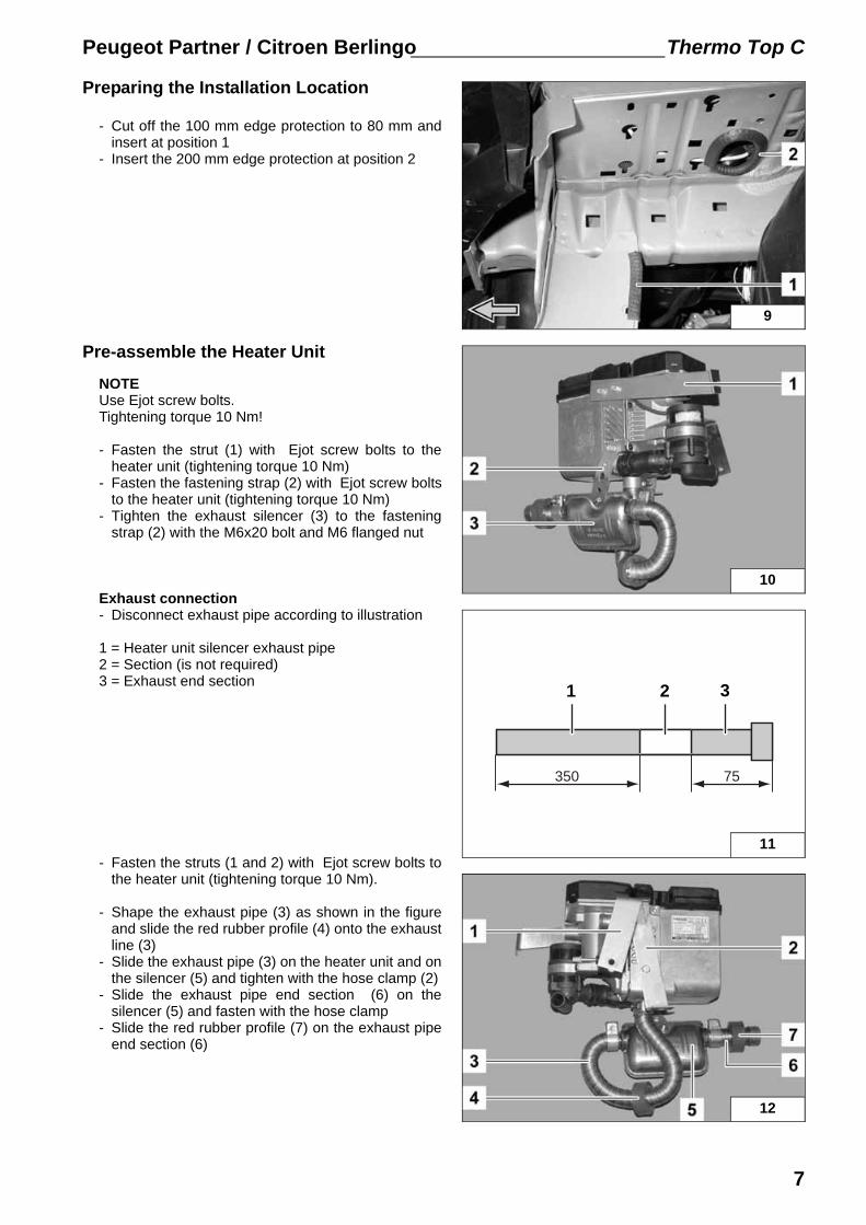
Pre-assemble the Heater Unit
NOTEUse Ejot screw bolts. Tightening torque 10 Nm!
- Fasten the strut (1) with Ejot screw bolts to theheater unit (tightening torque 10 Nm)
- Fasten the fastening strap (2) with Ejot screw boltsto the heater unit (tightening torque 10 Nm)
- Tighten the exhaust silencer (3) to the fasteningstrap (2) with the M6x20 bolt and M6 flanged nut
Exhaust connection- Disconnect exhaust pipe according to illustration
1 = Heater unit silencer exhaust pipe2 = Section (is not required)3 = Exhaust end section
- Fasten the struts (1 and 2) with Ejot screw bolts tothe heater unit (tightening torque 10 Nm).
- Shape the exhaust pipe (3) as shown in the figureand slide the red rubber profile (4) onto the exhaustline (3)
- Slide the exhaust pipe (3) on the heater unit and onthe silencer (5) and tighten with the hose clamp (2)
- Slide the exhaust pipe end section (6) on thesilencer (5) and fasten with the hose clamp
- Slide the red rubber profile (7) on the exhaust pipeend section (6)
7
Thermo Top C Peugeot Partner / Citroen Berlingo
13
14
15
16
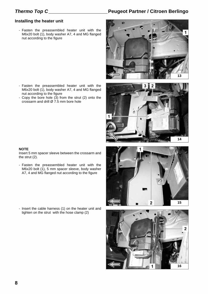
Installing the heater unit
- Fasten the preassembled heater unit with theM6x20 bolt (1), body washer A7, 4 and MG flangednut according to the figure
- Fasten the preassembled heater unit with theM6x20 bolt (1), body washer A7, 4 and MG flangednut according to the figure
- Copy the bore hole (3) from the strut (2) onto thecrossarm and drill Ø 7.5 mm bore hole
NOTEInsert 5 mm spacer sleeve between the crossarm andthe strut (2).
- Fasten the preassembled heater unit with theM6x20 bolt (1), 5 mm spacer sleeve, body washerA7, 4 and MG flanged nut according to the figure
- Insert the cable harness (1) on the heater unit andtighten on the strut with the hose clamp (2)
8
Peugeot Partner / Citroen Berlingo Thermo Top C
17
18
19
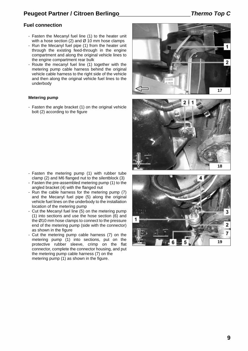
Fuel connection
- Fasten the Mecanyl fuel line (1) to the heater unitwith a hose section (2) and Ø 10 mm hose clamps
- Run the Mecanyl fuel pipe (1) from the heater unitthrough the existing feed-through in the enginecompartment and along the original vehicle lines tothe engine compartment rear bulk
- Route the mecanyl fuel line (1) together with themetering pump cable harness behind the originalvehicle cable harness to the right side of the vehicleand then along the original vehicle fuel lines to theunderbody
Metering pump
- Fasten the angle bracket (1) on the original vehiclebolt (2) according to the figure
- Fasten the metering pump (1) with rubber tubeclamp (2) and M6 flanged nut to the silentblock (3)
- Fasten the pre-assembled metering pump (1) to theangled bracket (4) with the flanged nut
- Run the cable harness for the metering pump (7)and the Mecanyl fuel pipe (5) along the originalvehicle fuel lines on the underbody to the installationlocation of the metering pump
- Cut the Mecanyl fuel line (5) on the metering pump(1) into sections and use the hose section (6) andthe Ø10 mm hose clamps to connect to the pressureend of the metering pump (side with the connector)as shown in the figure
- Cut the metering pump cable harness (7) on themetering pump (1) into sections, put on theprotective rubber sleeve, crimp on the flatconnector, complete the connector housing, and putthe metering pump cable harness (7) on the metering pump (1) as shown in the figure.
9
Thermo Top C Peugeot Partner / Citroen Berlingo
20
21
22
23
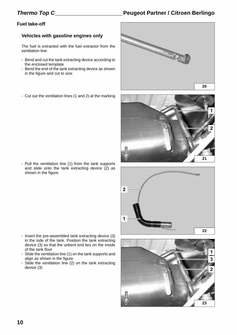
Fuel take-off
Vehicles with gasoline engines only
The fuel is extracted with the fuel extractor from theventilation line.
- Bend and cut the tank extracting device according tothe enclosed template
- Bend the end of the tank extracting device as shownin the figure and cut to size
- Cut out the ventilation lines (1 and 2) at the marking
- Pull the ventilation line (1) from the tank supportsand slide onto the tank extracting device (2) asshown in the figure
- Insert the pre-assembled tank extracting device (3)in the side of the tank. Position the tank extractingdevice (3) so that the unbent end lies on the insideof the tank floor
- Slide the ventilation line (1) on the tank supports andalign as shown in the figure
- Slide the ventilation line (2) on the tank extractingdevice (3)
10
Peugeot Partner / Citroen Berlingo Thermo Top C
24
26
27
25
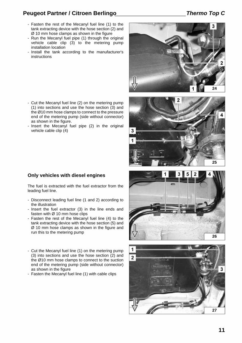
- Fasten the rest of the Mecanyl fuel line (1) to thetank extracting device with the hose section (2) andØ 10 mm hose clamps as shown in the figure
- Run the Mecanyl fuel pipe (1) through the originalvehicle cable clip (3) to the metering pumpinstallation location
- Install the tank according to the manufacturer'sinstructions
- Cut the Mecanyl fuel line (2) on the metering pump(1) into sections and use the hose section (3) andthe Ø10 mm hose clamps to connect to the pressureend of the metering pump (side without connector)as shown in the figure.
- Insert the Mecanyl fuel pipe (2) in the originalvehicle cable clip (4)
Only vehicles with diesel engines
The fuel is extracted with the fuel extractor from theleading fuel line.
- Disconnect leading fuel line (1 and 2) according tothe illustration
- Insert the fuel extractor (3) in the line ends andfasten with Ø 10 mm hose clips
- Fasten the rest of the Mecanyl fuel line (4) to thetank extracting device with the hose section (5) andØ 10 mm hose clamps as shown in the figure andrun this to the metering pump
- Cut the Mecanyl fuel line (1) on the metering pump(3) into sections and use the hose section (2) andthe Ø10 mm hose clamps to connect to the suctionend of the metering pump (side without connector)as shown in the figure
- Fasten the Mecanyl fuel line (1) with cable clips
11
Thermo Top C Peugeot Partner / Citroen Berlingo
29
740 660
2 3
1
a
30
980 890
2 3
1
a
28
600 540
2 3
1
a
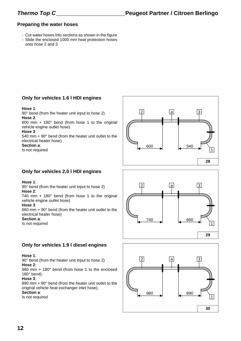
Preparing the water hoses
- Cut water hoses into sections as shown in the figure- Slide the enclosed 1000 mm heat protection hoses
onto hose 2 and 3
Only for vehicles 1.6 l HDI engines
Hose 1:90° bend (from the heater unit input to hose 2)Hose 2:600 mm + 180° bend (from hose 1 to the originalvehicle engine outlet hose).Hose 3:540 mm + 90° bend (from the heater unit outlet to theelectrical heater hose)Section a:Is not required
Only for vehicles 2.0 l HDI engines
Hose 1:90° bend (from the heater unit input to hose 2)Hose 2:740 mm + 180° bend (from hose 1 to the originalvehicle engine outlet hose).Hose 3:660 mm + 90° bend (from the heater unit outlet to theelectrical heater hose)Section a:Is not required
Only for vehicles 1.9 l diesel engines
Hose 1:90° bend (from the heater unit input to hose 2)Hose 2:980 mm + 180° bend (from hose 1 to the enclosed180° bend).Hose 3:890 mm + 90° bend (from the heater unit outlet to theoriginal vehicle heat exchanger inlet hose).Section a:Is not required
12
Peugeot Partner / Citroen Berlingo Thermo Top C
31
780 700
2 3
1
a
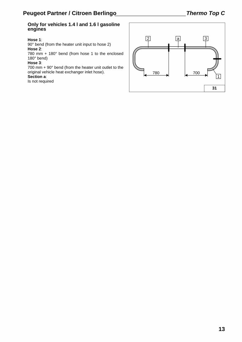
Only for vehicles 1.4 l and 1.6 l gasoline engines
Hose 1:90° bend (from the heater unit input to hose 2)Hose 2:780 mm + 180° bend (from hose 1 to the enclosed180° bend)Hose 3:700 mm + 90° bend (from the heater unit outlet to theoriginal vehicle heat exchanger inlet hose).Section a:Is not required
13
Thermo Top C Peugeot Partner / Citroen Berlingo
32
33
34
35
Water connection
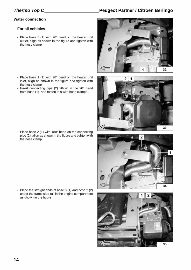
For all vehicles
- Place hose 3 (1) with 90° bend on the heater unitoutlet, align as shown in the figure and tighten withthe hose clamp
- Place hose 1 (1) with 90° bend on the heater unitinlet, align as shown in the figure and tighten withthe hose clamp
- Insert connecting pipe (2) 20x20 in the 90° bendfrom hose (1) and fasten this with hose clamps
- Place hose 2 (1) with 180° bend on the connectingpipe (2), align as shown in the figure and tighten withthe hose clamp
- Place the straight ends of hose 3 (1) and hose 2 (2)under the frame side rail in the engine compartmentas shown in the figure
14

Peugeot Partner / Citroen Berlingo Thermo Top C
38
1
2
36
1
2
3712
Only for vehicles 1.6 l HDI engines
- Disconnect the original vehicle engine outlet hose toheat exchanger inlet (2) at the engine outletsupports. The original vehicle spring band clamp (1)will be used again.
- Slide enclosed 180° bend (1) on the engine outletsupports and fasten with the hose clamp as shownin the figure
- Connect hose 2 (2) from the heater unit inlet and the180° bend (1) from the engine outlet with theconnecting pipe 18x20mm and hose clamps asshown in the figure
- Connect hose 3 (2) from the heater unit outlet andoriginal vehicle hose (1) for the heat exchange inletwith connecting pipe 18x20 and hose clamps as wellas the original vehicle spring band clamp as shownin the figure
- Fasten the hose 3 (2) and original vehicle hose (1)with cable ties
15
Thermo Top C Peugeot Partner / Citroen Berlingo
CI 0027 W1
8,5
mm
39
40
41
42
Only for vehicles 2.0 l HDI engines
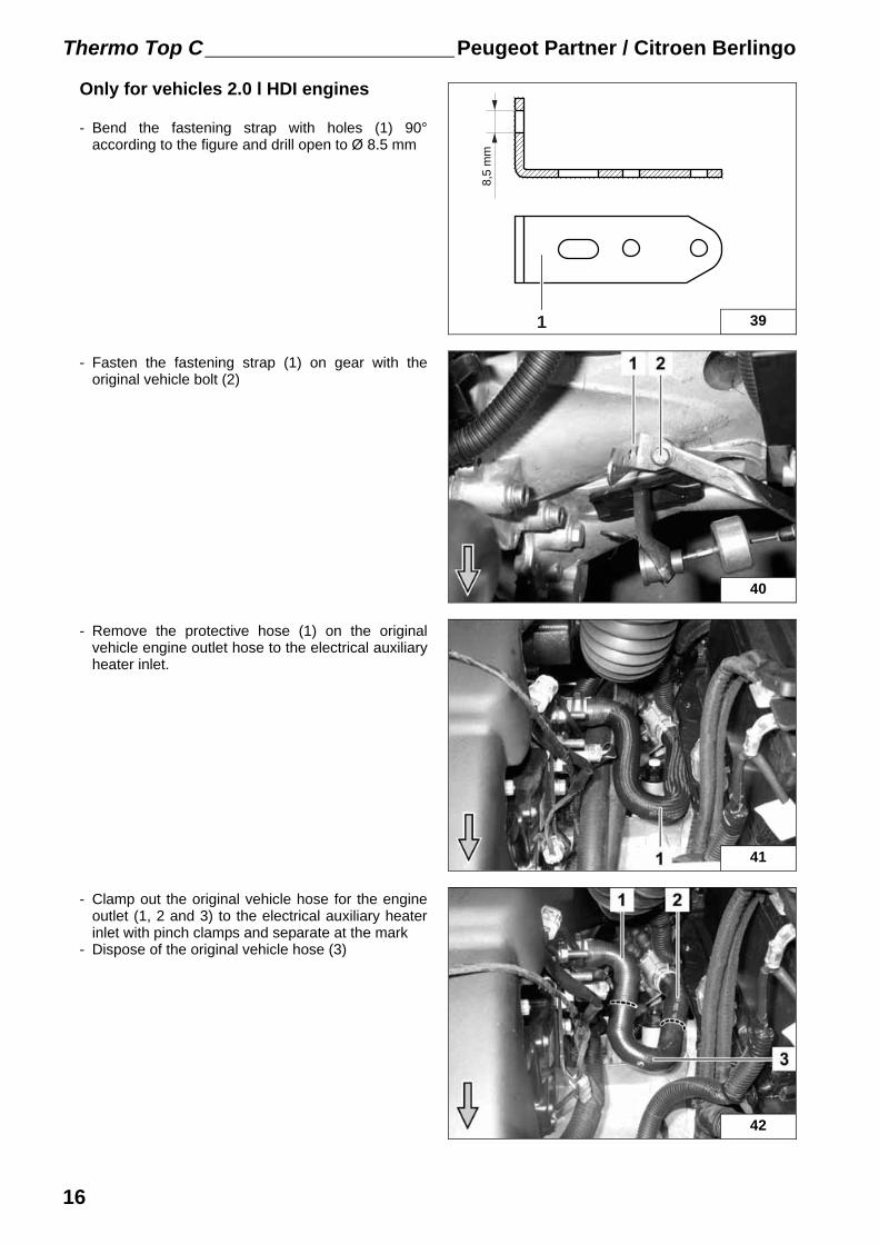
- Bend the fastening strap with holes (1) 90°according to the figure and drill open to Ø 8.5 mm
- Fasten the fastening strap (1) on gear with theoriginal vehicle bolt (2)
- Remove the protective hose (1) on the originalvehicle engine outlet hose to the electrical auxiliaryheater inlet.
- Clamp out the original vehicle hose for the engineoutlet (1, 2 and 3) to the electrical auxiliary heaterinlet with pinch clamps and separate at the mark
- Dispose of the original vehicle hose (3)
16
Peugeot Partner / Citroen Berlingo Thermo Top C
46
CI 0027 W1
8,5
mm
45
44
43
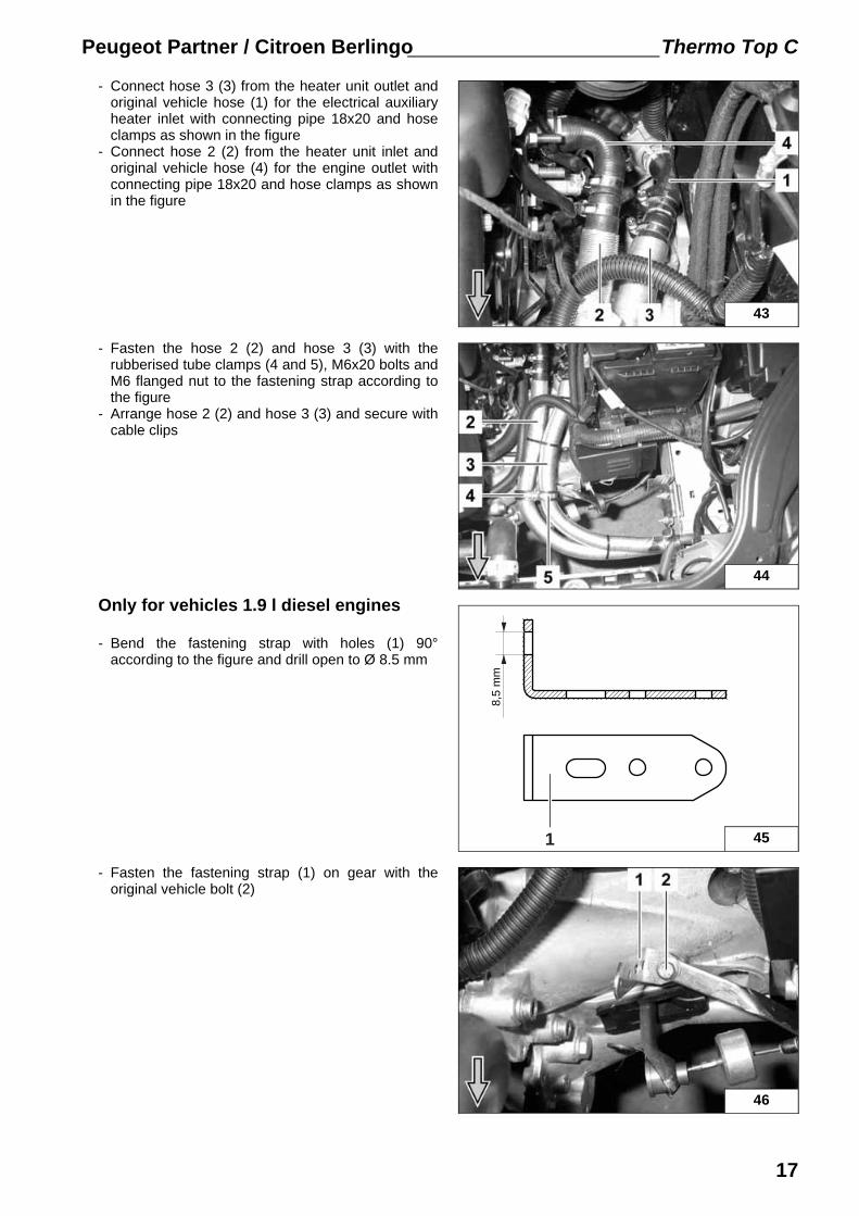
- Connect hose 3 (3) from the heater unit outlet andoriginal vehicle hose (1) for the electrical auxiliaryheater inlet with connecting pipe 18x20 and hoseclamps as shown in the figure
- Connect hose 2 (2) from the heater unit inlet andoriginal vehicle hose (4) for the engine outlet withconnecting pipe 18x20 and hose clamps as shownin the figure
- Fasten the hose 2 (2) and hose 3 (3) with therubberised tube clamps (4 and 5), M6x20 bolts andM6 flanged nut to the fastening strap according tothe figure
- Arrange hose 2 (2) and hose 3 (3) and secure withcable clips
Only for vehicles 1.9 l diesel engines
- Bend the fastening strap with holes (1) 90°according to the figure and drill open to Ø 8.5 mm
- Fasten the fastening strap (1) on gear with theoriginal vehicle bolt (2)
17
Thermo Top C Peugeot Partner / Citroen Berlingo
47
48
49
50
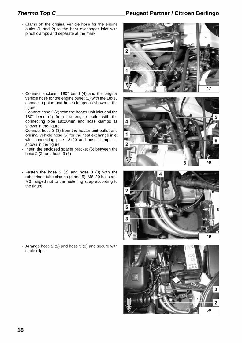
- Clamp off the original vehicle hose for the engineoutlet (1 and 2) to the heat exchanger inlet withpinch clamps and separate at the mark
- Connect enclosed 180° bend (4) and the originalvehicle hose for the engine outlet (1) with the 18x18connecting pipe and hose clamps as shown in thefigure
- Connect hose 2 (2) from the heater unit inlet and the180° bend (4) from the engine outlet with theconnecting pipe 18x20mm and hose clamps asshown in the figure
- Connect hose 3 (3) from the heater unit outlet andoriginal vehicle hose (5) for the heat exchange inletwith connecting pipe 18x20 and hose clamps asshown in the figure
- Insert the enclosed spacer bracket (6) between thehose 2 (2) and hose 3 (3)
- Fasten the hose 2 (2) and hose 3 (3) with therubberised tube clamps (4 and 5), M6x20 bolts andM6 flanged nut to the fastening strap according tothe figure
- Arrange hose 2 (2) and hose 3 (3) and secure withcable clips
18
Peugeot Partner / Citroen Berlingo Thermo Top C
CI 0027 W1
8,5
mm
51
52
38
53
54
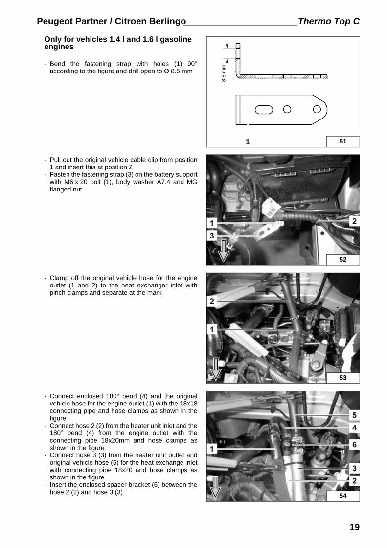
Only for vehicles 1.4 l and 1.6 l gasoline engines
- Bend the fastening strap with holes (1) 90°according to the figure and drill open to Ø 8.5 mm
- Pull out the original vehicle cable clip from position1 and insert this at position 2
- Fasten the fastening strap (3) on the battery supportwith M6 x 20 bolt (1), body washer A7.4 and MGflanged nut
- Clamp off the original vehicle hose for the engineoutlet (1 and 2) to the heat exchanger inlet withpinch clamps and separate at the mark
- Connect enclosed 180° bend (4) and the originalvehicle hose for the engine outlet (1) with the 18x18connecting pipe and hose clamps as shown in thefigure
- Connect hose 2 (2) from the heater unit inlet and the180° bend (4) from the engine outlet with theconnecting pipe 18x20mm and hose clamps asshown in the figure
- Connect hose 3 (3) from the heater unit outlet andoriginal vehicle hose (5) for the heat exchange inletwith connecting pipe 18x20 and hose clamps asshown in the figure
- Insert the enclosed spacer bracket (6) between thehose 2 (2) and hose 3 (3)
19
Thermo Top C Peugeot Partner / Citroen Berlingo
55
56
57
58
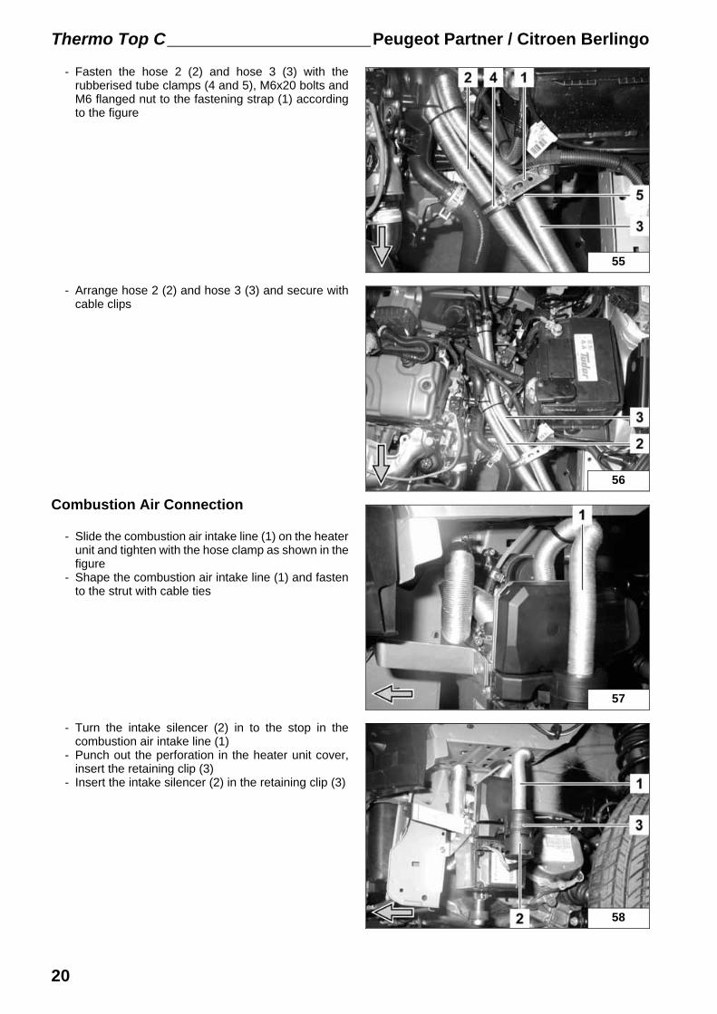
- Fasten the hose 2 (2) and hose 3 (3) with therubberised tube clamps (4 and 5), M6x20 bolts andM6 flanged nut to the fastening strap (1) accordingto the figure
- Arrange hose 2 (2) and hose 3 (3) and secure withcable clips
Combustion Air Connection
- Slide the combustion air intake line (1) on the heaterunit and tighten with the hose clamp as shown in thefigure
- Shape the combustion air intake line (1) and fastento the strut with cable ties
- Turn the intake silencer (2) in to the stop in thecombustion air intake line (1)
- Punch out the perforation in the heater unit cover,insert the retaining clip (3)
- Insert the intake silencer (2) in the retaining clip (3)
20
Peugeot Partner / Citroen Berlingo Thermo Top C
59
60
61
62
Final work
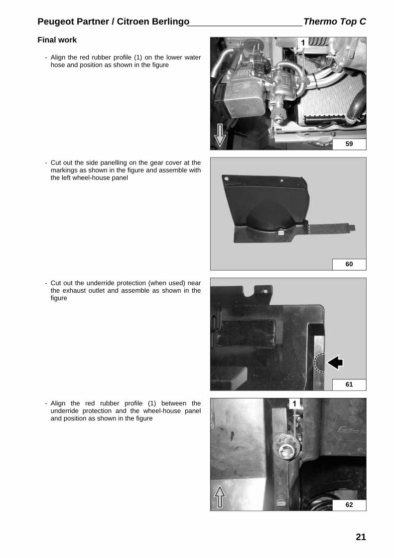
- Align the red rubber profile (1) on the lower waterhose and position as shown in the figure
- Cut out the side panelling on the gear cover at themarkings as shown in the figure and assemble withthe left wheel-house panel
- Cut out the underride protection (when used) nearthe exhaust outlet and assemble as shown in thefigure
- Align the red rubber profile (1) between theunderride protection and the wheel-house paneland position as shown in the figure
21

Thermo Top C Peugeot Partner / Citroen Berlingo
i
WARNING!
Reassemble disassembled components in reverse order.Check that all hose lines, hose, spring band clamps and universal clips, and all electrical connections are securely fastened.Secure all loose cables using cable clips.Only use manufacturer-approved coolant.Spray heating unit components with anti-corrosion wax (Tectyl 100K, Order No. 111329).
- Connect battery- Fill and bleed the coolant circuit according to the vehicle manufacturer’s specifications- Set the time switch- Make settings according to "Operating instructions for the end customer"- Check that the auxiliary heating operates properly, see operating instructions / installation instructions- Attach the "Switch off auxiliary heating before re-fuelling" sticker onto the left side of the B-pillar
Webasto AGPostfach 80 - 82132 Stockdorf - Hotline 0 18 05 / 93 22 78Hotfax (0395) 55 92-353 - http://www.webasto.de
Feel the drive
22Printed in Germany 07/06Printed by: Steffen
Peugeot Partner / Citroen Berlingo Thermo Top C
63
Operating instructions for the end customer
Please remove page and add to the vehicle operating instructions.
Before parking the vehicle, make the followingsettings:
- Switch to "Defrost" (1)- Temperature to "max." (2)- Blower to setting "1“ (3)
23
Peugeot Partner / Citroen Berlingo Thermo Top C
24
Template
CI 0050 W64