Embed Size (px)
Citation preview

MAKE: STYLE:
45
WARNING: NEVER EXCEED YOUR VEHICLE MANUFACTURER'S RECOMMENDED TOWING CAPACITYFor more information log onto www.curtmfg.com & for helpful towing tips log onto www.hitchinfo.com
WEIGHT CARRYING:
INSTALLATION TIPS:
INSTALLATION REQUIRES:
VEHICLE PHOTO:
HITCH ILLUSTRATION:
REPRESENTATIVE PHOTO
MAKE SURE YOUR HITCH MATCHES
LEVEL OF DIFFICULTY: MODERATE
EASY MODERATE CHALLENGING
1. BEFORE YOU BEGIN INSTALLATION, READ ALL INSTRUCTIONS THOROUGHLY. 2. TO EASE INSTALLATION, 2 PEOPLE MAY BE REQUIRED. 3. USING PROPER TOOLS WILL GREATLY IMPROVE THE QUALITY OF THE INSTALL AND REDUCE THE TIME REQUIRED. 4. NEED HELP OR HAVE SOME QUESTIONS? CALL TECHNICAL SUPPORT AT 800.798.0813
Safety glasses should be worn at all times whileinstalling this product.
YEARS: 2017-CURRENT HYUNDAI MODEL: ELANTRA SEDAN
2,000200
TRAILER WEIGHT:TONGUE WEIGHT:
11424 INSTALLATION INSTRUCTIONS
LBS.LBS.
WARNING: WE RECOMMEND THE USE OF 18050 STABILIZING STRAPS FOR ALL NON-TRAILER (WHEEL-LESS) LOADS. PLEASE SEE THE CURT CATALOG OR VISIT US ONLINE AT WWW.CURTMFG.COM FOR FURTHER INFORMATION.
90 MIN.MIN. PRO INSTALL TIME:
NOVICE INSTALL TIME:
IF YOU ARE HESITANT TO UNDERTAKETHIS TASK ON YOUR OWN, CONTACT AN AUTHORIZED
CURT INSTALLER FOR ADDITIONAL ASSISTANCE.
SCAN FORMORE INFO
PERIODICALLY CHECK THIS RECEIVER HITCH TO ENSURE ALL FASTENERS ARE TIGHT AND ALL STRUCTURAL COMPONENTS ARE SOUNDCURT Manufacturing LLC. warrants this product to be free of defects in material and/or workmanship at the time of retail purchase by the original purchaser. If the product is found to be defective,CURT Manufacturing LLC. may repair or replace the product at their option, when the product is returned, prepaid, with proof of purchase. Alteration to, misuse of, or improper installation of this productvoids the warranty. CURT Manufacturing LLC.'s liability is limited to repair or replacement of products found to be defective, and specifically excludes liability for incidental or consequential loss or damage.For more information log onto www.curtmfg.com, & for helpful towing tips log onto www.hitchinfo.comThis product complies with safety specifications and requirements for connecting devices and towing systems of the state of New York, V.E.S.C.Regulation V-5 and SAE J684. 2/26/2016
SCREWDRIVER SOCKET
10mm15mm17mm9/16" SOCKET
EXTENSION
6"
RATCHETTORQUE
WRENCHMASKING
TAPE
TAPEMEASUREDIE GRINDER
NO DRILLING REQUIRED
LOWER EXHAUST
TRIM UNDERBODY PANEL

INSTALLATION WALKTHROUGH:
For more information log onto www.curtmfg.com, & for helpful towing tips log onto www.hitchinfo.com
Parts List
DESCRIPTIONPART NUMBERQTYITEM
3/8-16 x 1.938 x .875" U-BOLTCM-3805-UBR11
HEX BOLTM10-1.25 x 3542
CONICAL TOOTHED WASHER7/16"43
HEX NUT3/8 - 1624
LOCK WASHER3/8"25
WASHER5/16"26
EXISTING VEHICLE TOW LOOP
DRIVER SIDEFRAME RAIL
DESIGNED FOR USE WITHBALL MOUNT # D-21 / 45521
EURO MOUNT OPTION AVAILABLE#45571 (1-7/8" BALL) #45572 (2" BALL)
PASSENGER SIDEFRAME RAIL
1
2 3
4
5
6
1. Lower exhaust by detaching (2) rubber isolators towards rear of vehicle. (See RUBBER ISOLATOR REMOVEL DIAGRAM)
2. Temporarily remove driver side underbody panel by removing (3) clips using a flat head screwdriver and (4) nuts using a 10mm socket.

INSTALLATION WALKTHROUGH:
For more information log onto www.curtmfg.com, & for helpful towing tips log onto www.hitchinfo.com
3. Remove (2) bolts using a 15mm socket on driver and passenger sides of vehicle on front facing section that attaches to the bumper beam. Place 3/8" u-bolt over vehicle tow loop.
4. Raise hitch into position and slide u-bolt through holes in hitch. Secure hitch to vehicle with M10 bolts and 7/16" conical toothed washers into locations where bolts were removed in step 3. Install 5/16" flat washers, 3/8" lock washers and 3/8" hex nuts onto u-bolt.
5. Torque M10 hardware to 86 lb-ft and 3/8" hardware to 26 lb-ft.
6. Mark cut location of underbody panel. (See UNDERBODY PANEL TRIM DIAGRAM) Cut out marked location using cutoff wheel.
1 in1.75 in
3.5 in

INSTALLATION WALKTHROUGH:
For more information log onto www.curtmfg.com, & for helpful towing tips log onto www.hitchinfo.com
7. Reinstall underbody panel in reverse order of step 2. Raise exhaust into position and reattach exhaust isolators.


GROSS LOAD CAPACITY WHEN USED AS A WEIGHT CARRYING HITCH: LBS. TRAILER WEIGHT & LBS. TONGUE WEIGHT.
WARNING: ALL NON-TRAILER LOADS APPLIED TO THIS PRODUCT MUST BE SUPPORTED BY 18050 STABILIZING STRAPS.
WARNING: ** FAILURE TO PROPERLY SUPPORT NON-TRAILER LOADS WILL VOID PRODUCT WARRANTY **
WARNING: *** DO NOT EXCEED VEHICLE MANUFACTURER'S RECOMMENDED TOWING CAPACITY ***FOR MORE INFORMATION LOG ONTO WWW.CURTMFG.COM & FOR HELPFUL TOWING TIPS LOG ONTO WWW.HITCHINFO.COM
HAVING INSTALLATION QUESTIONS? CALL TECHNICAL SUPPORT AT 1-800-798-0813
HITCH WEIGHT: LBS.
INSTALL TIME
PROFESSIONAL: MINUTES
NOVICE (DIY): MINUTES
INSTALL NOTES:
PERIODICALLY CHECK THIS RECEIVER HITCH TO ENSURE THAT ALL FASTENERSARE TIGHT AND THAT ALL STRUCTURAL COMPONENTS ARE SOUND.
CURT Manufacturing LLC., warrants this product to be free of defects in material and/or workmanship at the time of retail purchase by the original purchaser. If the product is found to be defective, CURT Manufacturing LLC., may repair or replace the product, at their option, when the product is returned, prepaid, with proof of purchase. Alteration to, misuse of, or improper installation of this product voids the warranty. CURT Manufacturing LLC.'s liability is limited to repair or replacement of products found to be defective, and specifically excludes liability for incidental or consequential loss or damage.This product complies with safety specifications and requirements for connecting devices and towing systems of the state of New York, V.E.S.C.Regulation V-5 and SAE J684.
2,000 200
24
45
HYUNDAI ELANTRA2/25/201611424
90
Scanfor moreinformation
PAGE 1 of 2
Parts ListDESCRIPTIONPART NUMBERQTYITEM
3/8-16 x 1.938 x .875" U-BOLTCM-3805-UBR11HEX NUT3/8 - 1622LOCK WASHER3/8"23WASHER5/16"24HEX BOLTM10-1.25 x 3545CONICAL TOOTHED WASHER7/16"46 5 6
1
4
3
2
EXISTING VEHICLE TOW LOOP
PASSENGER SIDEFRAME RAIL
DRIVER SIDEFRAME RAIL
DESIGNED FOR USE WITHBALL MOUNT # D-21 / 45521
EURO MOUNT OPTION AVAILABLE#45571 (1-7/8" BALL) #45572 (2" BALL)
- NO DRILLING REQUIRED- LOWER EXHAUST- TRIM UNDERBODY PANEL
TOOLS REQUIREDFLAT HEAD SCREWDRIVER10mm,15mm,17mm SOCKET
9/16" SOCKET6" SOCKET EXTENSION
SOCKET WRENCHTORQUE WRENCH
TAPECUTOFF WHEELTAPE MEASURE
HAVING INSTALLATION QUESTIONS? CALL TECHNICAL SUPPORT AT 1-800-798-0813
INSTALLATION STEPS
PERIODICALLY CHECK THIS RECEIVER HITCH TO ENSURE THAT ALL FASTENERSARE TIGHT AND THAT ALL STRUCTURAL COMPONENTS ARE SOUND.
CURT Manufacturing LLC., warrants this product to be free of defects in material and/or workmanship at the time of retail purchase by the original purchaser. If the product is found to be defective, CURT Manufacturing LLC., may repair or replace the product, at their option, when the product is returned, prepaid, with proof of purchase. Alteration to, misuse of, or improper installation of this product voids the warranty. CURT Manufacturing LLC.'s liability is limited to repair or replacement of products found to be defective, and specifically excludes liability for incidental or consequential loss or damage.
This product complies with safety specifications and requirements for connecting devices and towing systems of the state of New York, V.E.S.C.Regulation V-5 and SAE J684.
HYUNDAI ELANTRA2/25/2016
11424PAGE 2 of 2
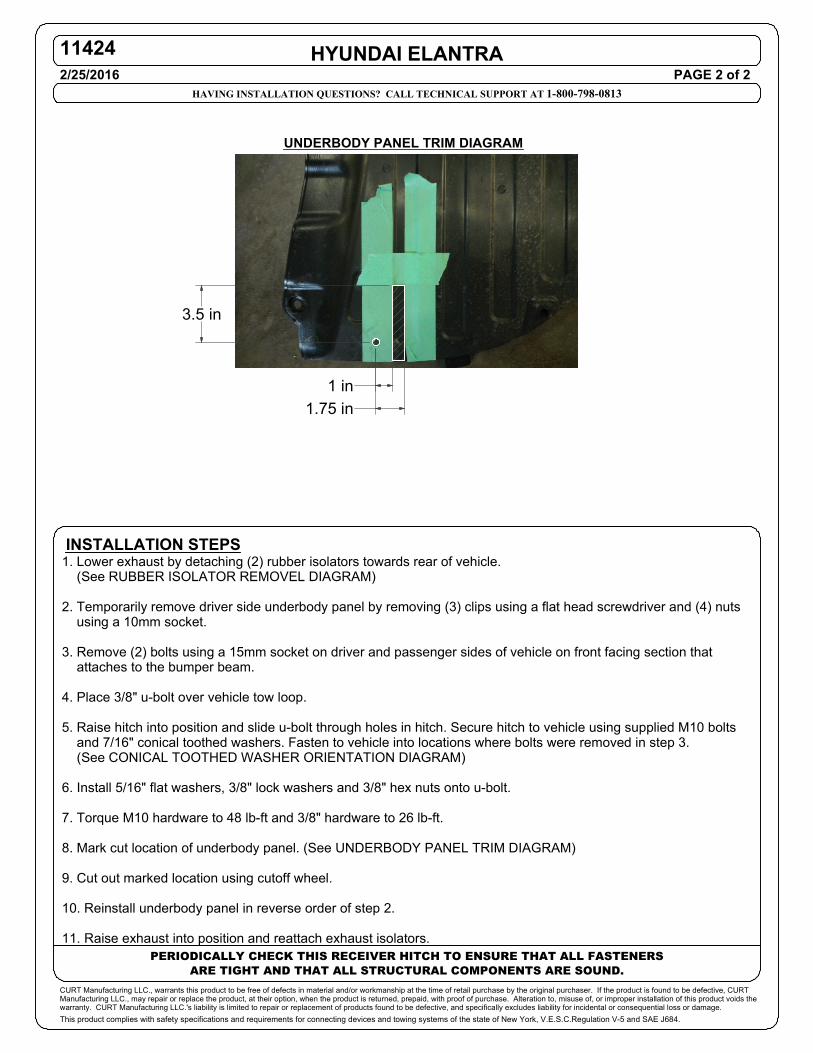
1. Lower exhaust by detaching (2) rubber isolators towards rear of vehicle. (See RUBBER ISOLATOR REMOVEL DIAGRAM) 2. Temporarily remove driver side underbody panel by removing (3) clips using a flat head screwdriver and (4) nuts using a 10mm socket. 3. Remove (2) bolts using a 15mm socket on driver and passenger sides of vehicle on front facing section that attaches to the bumper beam. 4. Place 3/8" u-bolt over vehicle tow loop. 5. Raise hitch into position and slide u-bolt through holes in hitch. Secure hitch to vehicle using supplied M10 bolts and 7/16" conical toothed washers. Fasten to vehicle into locations where bolts were removed in step 3. (See CONICAL TOOTHED WASHER ORIENTATION DIAGRAM) 6. Install 5/16" flat washers, 3/8" lock washers and 3/8" hex nuts onto u-bolt. 7. Torque M10 hardware to 48 lb-ft and 3/8" hardware to 26 lb-ft. 8. Mark cut location of underbody panel. (See UNDERBODY PANEL TRIM DIAGRAM) 9. Cut out marked location using cutoff wheel. 10. Reinstall underbody panel in reverse order of step 2. 11. Raise exhaust into position and reattach exhaust isolators.
1 in1.75 in
3.5 in
UNDERBODY PANEL TRIM DIAGRAM