Embed Size (px)
Citation preview

1 | P a g e
Radiant Floor Heat Installation Instructions & Owner’s Manual
1 | P a g e
Contents General .................................................................................................. 2
Temperature Control ............................................................................. 2
Maintenance .......................................................................................... 2
Design Power ......................................................................................... 2
Design Power (con’t) .............................................................................. 3
Custom Design ....................................................................................... 3
Before you Install ................................................................................... 4
Subfloors ................................................................................................ 4
Floor Coverings ...................................................................................... 4
Precautions ............................................................................................ 5
Do’s ........................................................................................................ 5
Don’ts ..................................................................................................... 5
Circuit Checker Operation ..................................................................... 6
Electrical tests ........................................................................................ 6
INSTALLATION ........................................................................................ 6
Electrical Rough‐In ................................................................................. 6
Floor Sensor Placement ......................................................................... 7
Subfloor Preparation ............................................................................. 7
Packaging Removal & Inspection ........................................................... 7
Perform Electrical Test #1 ...................................................................... 8
Check panel fit ....................................................................................... 8
Mark the floor ........................................................................................ 9
Cold Leads & Floor Sensor Channels ...................................................... 9
Secure Temperature Sensor to Subfloor ............................................. 10
Secure Heat Panel to the Subfloor ....................................................... 10
Method 1 – Stapling ............................................................................. 11
Method 2 – Taping ............................................................................... 11
Method 3 – Gluing................................................................................ 11
Perform Electrical Test #2 .................................................................... 11
Test floor sensor resistance ................................................................. 12
Flooring installation .............................................................................. 12
Ceramic Tile, Porcelain Tile, Marble, and Other Stone Flooring – 1 step Process ................................................................................................. 12
Ceramic Tile, Porcelain Tile, Marble, and Other Stone Flooring – 2 step Process ................................................................................................. 12
Carpet, Vinyl, Linoleum, Glue Down Wood, Laminate and Floating Floor ..................................................................................................... 13
Laminate & Floating Floor Installation Option 2 .................................. 13
Perform Electrical Test #3 .................................................................... 14
Controller installation .......................................................................... 14
Label installation .................................................................................. 14
Sunstat Controller Operation ............................................................... 15
Resistance Check Table ........................................................................ 18
Warnings .............................................................................................. 18
Aries Engineering Radiant Floor Heat Installation Instructions & Owner’s Manual
2 | P a g e
General Aries Engineering radiant floor heating panel sets are designed to be used for primary and supplemental heating of indoor residential, commercial, and RV construction. These panels can be used with many subfloor types and finished flooring materials.
Our instruction manual will guide you through the complete installation. However, if you should have any questions before, during or after the installation of your radiant floor heating panel set, please call Aries Engineering Service at 866‐789‐4328.
Temperature Control Our radiant heating panels must be installed with an approved temperature limiting or regulating device. The recommended thermostat is the SunStat™ Controller.
This controller uses an external temperature sensor which is installed in the floor to control the floor temperature. It also has the ability to use ambient room temperature to control the floor temperature. This is desirable if the system is being used as the primary heat source for the room.
There is also an integrated floor temperature limit that can be set to limit the maximum floor temperature. To avoid possibly overheating your floor, you may use this option so that it turns your floor system off if the floor sensor exceeds a preset temperature.
Some wood and laminate floor manufacturers recommend a maximum temperature of 82° to 84°F. Check with the floor covering manufacturer for maximum temperature settings.
Each SunStat™ Controller will handle the operation of several mats as long as the total current rating of 15 Amps is not exceeded.
Our radiant heating panels must be installed on a circuit protected with a Ground Fault Circuit Interrupter (GFCI). The SunStat controller incorporates an integral GFCI.
For installations that exceed 15 amps total, multiple mats may be controlled using a single temperature controller and additional slave
relays. For information on installing a slave relay system contact the factory.
Maintenance Our radiant floor heating panels have no moving parts and is virtually maintenance‐free. The SunStat™ controller internal GFCI (Ground Fault Circuit Interrupt), should be tested monthly as described in the operating instructions section of this manual. If an external GFCI is utilized instead, it should also be tested monthly.
Design Power Be sure to use the right power density for your specific application. Standard radiant heat mats are manufactured at a power density of 12 ~ 15 watts/sq. ft for use under tile and natural stone floors.
For installation under carpet, laminate, or vinyl flooring, contact the factory for custom design. We will gladly assist in selecting the power output that is right for your application.
To ensure customer comfort and to safeguard your flooring product warranty, we recommend the following power guidelines.
Application Watts/sqft
Tile or natural stone 15
Laminate or Vinyl – Installed in mortar or self‐leveling floor compound
12
Carpet (Approved Grades) – Installed in mortar or self‐leveling floor compound
12
Laminate – Installed with or without adhesive mastic
10
Table 1
Aries Engineering Radiant Floor Heat Installation Instructions & Owner’s Manual
3 | P a g e
Design Power (con’t) Do not exceed 10 watts/sqft. If installing under laminate without mortar. Per the instructions to follow, our systems may be installed under laminate flooring and above the vapor barrier.
This installation is only authorized if mat power is 10 watts/sq ft or below. Using a higher‐power heat mat designed for tile for this installation method will void your warranty and may be a violation of electrical code.
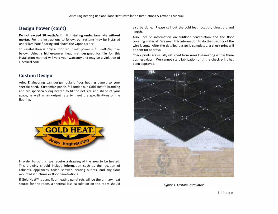
Custom Design Aries Engineering can design radiant floor heating panels to your specific need. Customize panels fall under our Gold Heat™ branding and are specifically engineered to fit the net size and shape of your space, as well as an output rate to meet the specifications of the flooring.
In order to do this, we require a drawing of the area to be heated. This drawing should include information such as the location of cabinets, appliances, toilet, shower, heating outlets, and any floor mounted structures or floor penetrations.
If Gold Heat™ radiant floor heating panel sets will be the primary heat source for the room, a thermal loss calculation on the room should
also be done. Please call out the cold lead location, direction, and length.
Also, include information on subfloor construction and the floor covering material. We need this information to do the specifics of the wire layout. After the detailed design is completed, a check print will be sent for approval.
Check prints are usually returned from Aries Engineering within three business days. We cannot start fabrication until the check print has been approved.
Figure 1. Custom Installation
Aries Engineering Radiant Floor Heat Installation Instructions & Owner’s Manual
4 | P a g e
Before you Install
Subfloors Our radiant floor heating panel sets are approved for application on surfaces such as: Clean, structurally sound, underlayment grade plywood, oriented strand board, backer board, wood, hardboard underlayment, association grade particleboard, concrete above grade in the absence of excessive moisture and/ or excessive alkali, and well bonded VCT* and sheet vinyl* (non‐embosses and non‐cushioned).
Subfloor must meet NWFA (National Hardwood Flooring Association) or American National Standard Specifications (ANSI) for quality, thickness, and maximum deflection. The subfloor must also comply with any local building code standards.
All materials in direct contact with the radiant floor heating panel MUST be rated to withstand 180°F. Our radiant floor heating panels will be most effective and efficient if installed over well‐insulated areas. Insulation will minimize heat loss into the subfloor and below (basement, ground), allowing the heat to transfer to the surface more quickly.
*Sheet Vinyl and VCT
• If at all possible, remove the old sheet vinyl or VCT. It is almost always a better choice to install over the original subfloor surface.
• Wood subfloors that are structurally suitable for vinyl may not be suitable for ceramic tile or wood floors. Double check the subfloor requirements from the manufacturer of the product to be installed.
• If not removed, the vinyl must be well adhered to the subfloor throughout the entire floor.
• If installing on top of vinyl, make sure the setting material used is approved for use on vinyl.
Floor Coverings Our radiant floor heating panel will be most effective if installed under rigid floor covering materials that are naturally good conductors of heat; such as ceramic tile, porcelain tile, marble, and other stone floorings.
There are limitations in applications that utilize other floor covering materials. Total combined R‐Values are not to exceed R‐ 2.5, R values for flooring material are available from the flooring manufacturer or other sources such as the Radiant Panel Association (RPA).
Installing the heating panel for use under carpet, vinyl, and glue down wood will require a leveling compound to be used with a minimum thickness of ¼”. This creates a level surface for the flooring material, protects the radiant floor heating panel from damage, and also helps with the thermal conductivity of the floor for successful operation.
When installing the radiant floor heating panel under floating laminate the method of using a leveling compound can be used, but the radiant floor heating panel can also be installed between the foam underlayment pad and the laminate material.
For more details on how to install Aries Engineering’s radiant floor heating panel sets using different flooring materials; see the appropriate section that follows.
Aries Engineering Radiant Floor Heat Installation Instructions & Owner’s Manual
5 | P a g e
Precautions
Do’s
• Clean the floor of all debris before placing the mat on the floor.
• Make sure there are no protruding objects; such as nails or staples, on the subfloor that could damage the radiant floor heating panel.
• Use rubber soled shoes if you need to walk over the unprotected heating panel.
• Keep traffic to a minimum on the heating panel until the leveling compound or final for covering is installed.
• Measure and record heating panel resistance as per instructions.
• Install floor sensor before installing flooring material or leveling compound.
• Make sure all components of the system are rated for the same Voltage (120V OR 240V).
• Have all electrical work completed by a professional electrician in accordance with all local and national codes.
• Connect the heating panel set to a dedicated electrical circuit.
• Call Aries Engineering Service at 866‐789‐4328 if you need answers to installation questions, need help solving a problem, or believe that the mat may have been damaged during installation.
Don’ts
• DON’T shorten the heating mat.
• DON’T cut the heating wire.
• DON’T cut the cold lead; the correct length should be determined during the design process.
• DON’T drop or bang any tools (i.e. trowel) on the heating wires.
• DON’T hit the heating wires with any sharp objects.
• DON’T install any fasteners such as nails, screws, etc. through any area covered by the heating panel.
• DON’T install radiant floor heating panel sets under cabinets, built‐in appliances, etc. to avoid excessive heat from building up in those areas.
• DON’T install mats over expansion joints.
• DON’T install heating panel sets in or under walls.
• DON’T overlap heating panels or allow any wires to cross or touch each other.
• DON’T place rubber backed area or throw rugs over the heated area to avoid excessive heat from building in these areas.
• DON’T attempt to repair the heating wire without the proper instructions and repair kit.
• DON’T install the heating panel in glues other than cement based tile‐setting mortars.
Aries Engineering Radiant Floor Heat Installation Instructions & Owner’s Manual
6 | P a g e
Circuit Checker Operation We recommend using the Honeywell circuit checker or similar device to monitor the heat mat health during installation and additional floor construction steps such as grouting. The circuit checker continuously monitors the electrical condition of the heating panel and if there is an open or short caused during the install process it will alert you of the failure so that it can be immediately addressed.
Using the circuit check is very simple.
1. First check the batteries on the circuit checker by switching it ON. If no audible alarm is heard, change the batteries.
2. Connect the one cold lead wire to the red terminal.
3. Connect the remaining cold lead wire to the black terminal.
4. Connect the grounding wire (braid) to the green terminal.
5. Switch ON the circuit checker. If an audible alarm is heard, stop work and contact Aries Engineering service for help.
Electrical tests During the installation process there is an electrical test that will need to be performed three times and the results written down on the warranty registration card and the back of this manual to keep for the owners records.
The electrical test involves the use of a digital multi‐meter. If you do not have, or know how to use this piece of equipment call Aries Engineering Service at 866‐789‐4328 for assistance.
The tests will be made on the factory end of the cold lead. On 120 Volt panels there will be three wires; white, black, and a green shield. On 240 Volt panels there will also be three wires; red, black, and a green shield.
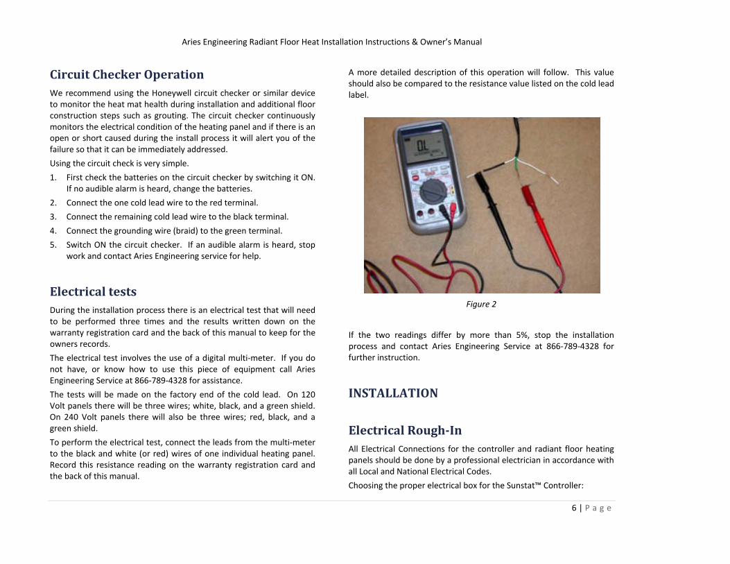
To perform the electrical test, connect the leads from the multi‐meter to the black and white (or red) wires of one individual heating panel. Record this resistance reading on the warranty registration card and the back of this manual.
A more detailed description of this operation will follow. This value should also be compared to the resistance value listed on the cold lead label.
Figure 2
If the two readings differ by more than 5%, stop the installation process and contact Aries Engineering Service at 866‐789‐4328 for further instruction.
INSTALLATION
Electrical RoughIn All Electrical Connections for the controller and radiant floor heating panels should be done by a professional electrician in accordance with all Local and National Electrical Codes.
Choosing the proper electrical box for the Sunstat™ Controller:
Aries Engineering Radiant Floor Heat Installation Instructions & Owner’s Manual
7 | P a g e
• If you are connecting cold leads from only 1 or 2 heating panels, you may use a single gang 3 ½” deep junction box.
• If you are connecting cold leads from 3 heating panels, you may use a 4” X 4” X 2 1/8” (or deeper) junction box. Install a single gang ‘mud ring’ cover on the box before installing drywall materials
If the installation requires the use of more than one heating panel in the same area the cold leads from the panel must be connected in parallel, not in series. This can be accomplished at the controller junction box, provided it is large enough, or in a separate junction box.
The AWG size and type of cable used to connect this junction box to the controller should be determined by the electrician to accommodate the amperage of the mats being installed.
A notch in the bottom plate will be needed to safely route the cold lead wire and the floor temperature sensor wire to the controller electrical box. After installation this notch should be covered with a nail plate to prevent accidental damage from installing drywall or trim.
The installation may be designed to split the area in to different zones. Separate controls may then be used for each zone. This would eliminate the need for a relay. However, the total amperage for each control must not exceed 15 Amps.
Floor Sensor Placement The floor sensor shall be installed onto the subfloor centered between two heating wires approximately 12‐24” into the heated area. The floor sensor location should not be under a cabinet, under or near a heat generating appliance, near a forced air heat outlet, in direct sunlight, or on top of the heating wire.
Another consideration is not to place the sensor where the owner may place a rug or furniture, the area above the sensor must not have a restricted air flow in order to provide satisfactory operation for the owner.
These details should have been covered during the design of the heating panel; however it is best to also verify this location in the field to ensure proper operation.
Subfloor Preparation Clean and inspect the subfloor or underlayment surface carefully before removing the heating panel from its’ packaging. Remove any sharp edges or pointed objects that might damage the heating wires.
Remove all dirt, dust, and debris from installation location, removal of this material after the heating panel is installed will be very difficult and prevent proper adhesion of setting materials to the subfloor. Repair all loose boards and fill gaps as needed to assure that the heating panel will be installed over a smooth, solid surface.
Subfloor must meet NWFA (National Hardwood Flooring Association) or American National Standard Specifications (ANSI) for quality, thickness, and maximum deflection. The subfloor must also comply with any local building code standards. All materials in direct contact with the heating panel must be rated to withstand 180°F.
Packaging Removal & Inspection Review the installation drawing included with the heating panel.
• Verify that all dimensions match the field dimensions.
• Verify length, location, and direction of the cold lead.
• Verify the supply voltage rating of the heating panel.
• Verify the location and orientation of the heating mat(s).
• Verify the controller location; indicate this location on the drawing if not already included.
• Verify the floor sensor location; indicate this location on the drawing if not already included.
• Verify junction box locations; indicate these locations on the drawing if not already included.
Aries Engineering Radiant Floor Heat Installation Instructions & Owner’s Manual
8 | P a g e
Contractor – The drawing for each heating panel should be attached to this manual and provided to the owner when the installation is complete.
Perform Electrical Test #1
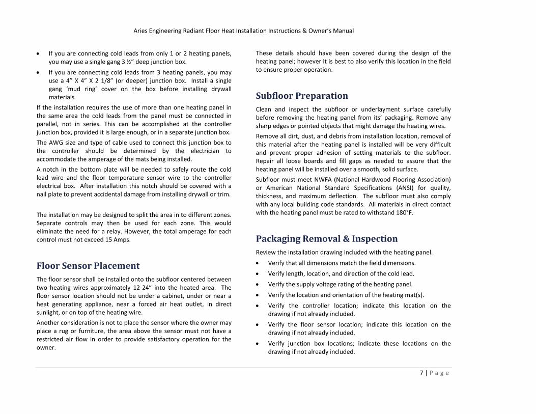
1. Check and record the information from the cold lead label onto the warranty registration card and the back of this manual.
2. When using a digital multi‐meter to check the heating wire resistance; use the 0‐200 Ohm scale.
Figure 3
3. Check the resistance of the heating wire. Connect a digital multi‐meter to the factory end of the cold lead attached to the heating panel. Connect to the black and white (red for 240 Volt panels) and measure the resistance. Record this measurement on the warranty registration card and the back of this manual. Compare this measurement with the value indicated on the cold lead. This value should differ by no more than 5%. If the difference is
greater than 5%; stop installation and contact Aries Engineering Service at 866‐789‐4328 for assistance.
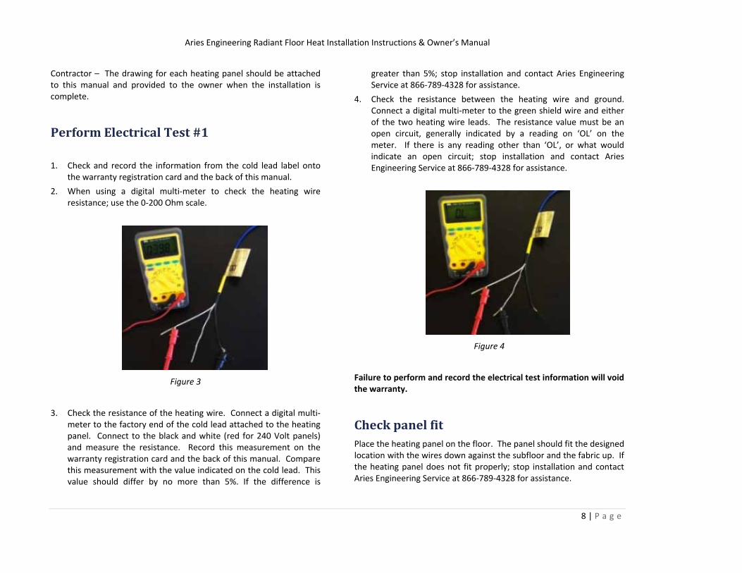
4. Check the resistance between the heating wire and ground. Connect a digital multi‐meter to the green shield wire and either of the two heating wire leads. The resistance value must be an open circuit, generally indicated by a reading on ‘OL’ on the meter. If there is any reading other than ‘OL’, or what would indicate an open circuit; stop installation and contact Aries Engineering Service at 866‐789‐4328 for assistance.
Figure 4
Failure to perform and record the electrical test information will void the warranty.
Check panel fit Place the heating panel on the floor. The panel should fit the designed location with the wires down against the subfloor and the fabric up. If the heating panel does not fit properly; stop installation and contact Aries Engineering Service at 866‐789‐4328 for assistance.
Aries Engineering Radiant Floor Heat Installation Instructions & Owner’s Manual
9 | P a g e
Do not install the heating panel if the wires are damaged or separated from the mesh backing. Heating panel must be installed within 90 days of manufacture for warranty to be valid. Install the heating panel when the temperature is above 50°F to ensure mat has adequate flexibility.
Do not allow any heating element wires to overlap or any cold lead wires to cross, touch or overlap the element wires at any point. Do not heat under items that are fixed to or flush with the floor.
The mats should be placed in open areas and directly in front of key areas. Some examples – the panel should run directly in front of the base of a vanity to heat the toe kick area properly. The panel can run slightly under the base of the toilet if need be, but should never be placed any closer than 4”‐6” from the flange.
Figure 5
Important – avoid cutting or nicking any of the heating element wires or the insulation around them.
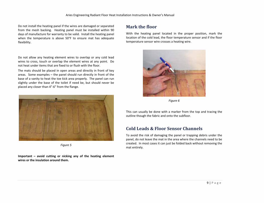
Mark the floor With the heating panel located in the proper position, mark the location of the cold lead, the floor temperature sensor and if the floor temperature sensor wire crosses a heating wire.
Figure 6
This can usually be done with a marker from the top and tracing the outline though the fabric and onto the subfloor.
Cold Leads & Floor Sensor Channels To avoid the risk of damaging the panel or trapping debris under the panel, do not leave the mat in the area where the channels need to be created. In most cases it can just be folded back without removing the mat entirely.
Aries Engineering Radiant Floor Heat Installation Instructions & Owner’s Manual
10 | P a g e
Figure 7
Figure 8
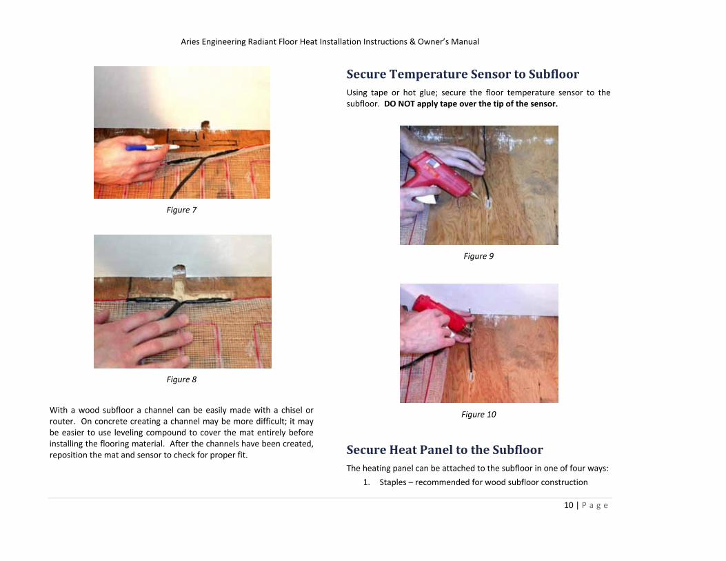
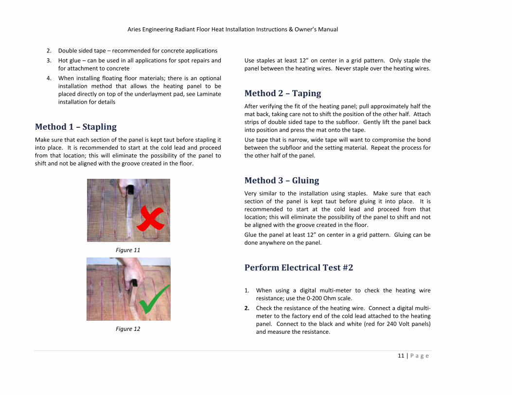
With a wood subfloor a channel can be easily made with a chisel or router. On concrete creating a channel may be more difficult; it may be easier to use leveling compound to cover the mat entirely before installing the flooring material. After the channels have been created, reposition the mat and sensor to check for proper fit.
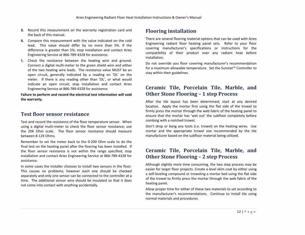
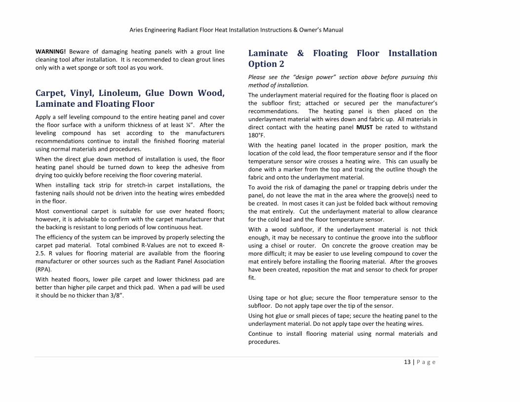
Secure Temperature Sensor to Subfloor Using tape or hot glue; secure the floor temperature sensor to the subfloor. DO NOT apply tape over the tip of the sensor.
Figure 9
Figure 10
Secure Heat Panel to the Subfloor The heating panel can be attached to the subfloor in one of four ways:
1. Staples – recommended for wood subfloor construction
Aries Engineering Radiant Floor Heat Installation Instructions & Owner’s Manual
11 | P a g e
2. Double sided tape – recommended for concrete applications
3. Hot glue – can be used in all applications for spot repairs and for attachment to concrete
4. When installing floating floor materials; there is an optional installation method that allows the heating panel to be placed directly on top of the underlayment pad, see Laminate installation for details
Method 1 – Stapling Make sure that each section of the panel is kept taut before stapling it into place. It is recommended to start at the cold lead and proceed from that location; this will eliminate the possibility of the panel to shift and not be aligned with the groove created in the floor.
Figure 11
Figure 12
Use staples at least 12” on center in a grid pattern. Only staple the panel between the heating wires. Never staple over the heating wires.
Method 2 – Taping After verifying the fit of the heating panel; pull approximately half the mat back, taking care not to shift the position of the other half. Attach strips of double sided tape to the subfloor. Gently lift the panel back into position and press the mat onto the tape.
Use tape that is narrow, wide tape will want to compromise the bond between the subfloor and the setting material. Repeat the process for the other half of the panel.
Method 3 – Gluing Very similar to the installation using staples. Make sure that each section of the panel is kept taut before gluing it into place. It is recommended to start at the cold lead and proceed from that location; this will eliminate the possibility of the panel to shift and not be aligned with the groove created in the floor.
Glue the panel at least 12” on center in a grid pattern. Gluing can be done anywhere on the panel.
Perform Electrical Test #2
1. When using a digital multi‐meter to check the heating wire resistance; use the 0‐200 Ohm scale.
2. Check the resistance of the heating wire. Connect a digital multi‐meter to the factory end of the cold lead attached to the heating panel. Connect to the black and white (red for 240 Volt panels) and measure the resistance.
Aries Engineering Radiant Floor Heat Installation Instructions & Owner’s Manual
12 | P a g e
3. Record this measurement on the warranty registration card and the back of this manual.
4. Compare this measurement with the value indicated on the cold lead. This value should differ by no more than 5%. If the difference is greater than 5%; stop installation and contact Aries Engineering Service at 866‐789‐4328 for assistance.
5. Check the resistance between the heating wire and ground. Connect a digital multi‐meter to the green shield wire and either of the two heating wire leads. The resistance value MUST be an open circuit, generally indicated by a reading on ‘OL’ on the meter. If there is any reading other than ‘OL’, or what would indicate an open circuit; stop installation and contact Aries Engineering Service at 866‐789‐4328 for assistance.
Failure to perform and record the electrical test information will void the warranty.
Test floor sensor resistance Test and record the resistance of the floor temperature sensor. When using a digital multi‐meter to check the floor sensor resistance; use the 20K Ohm scale. The floor sensor resistance should measure between 8‐12K Ohms.
Remember to set the meter back to the 0‐200 Ohm scale to do the final test on the heating panel after the flooring has been installed. If the floor sensor resistance is not within the range specified, stop installation and contact Aries Engineering Service at 866‐789‐4328 for assistance.
In some cases the installer chooses to install two sensors in the floor. This causes no problems; however each one should be checked separately and only one sensor can be connected to the controller at a time. The additional sensor wire should be insulated so that it does not come into contact with anything accidentally.
Flooring installation There are several flooring material options that can be used with Aries Engineering radiant floor heating panel sets. Refer to your floor covering manufacturer’s specifications or instructions for the compatibility of their product over any radiant heat before installation.
Do not override you floor covering manufacturer’s recommendation for a maximum allowable temperature. Set the Sunstat™ Controller to stay within their guidelines.
Ceramic Tile, Porcelain Tile, Marble, and Other Stone Flooring – 1 step Process After the tile layout has been determined; start at any desired location. Apply the mortar first using the flat side of the trowel to firmly press the mortar through the web fabric of the heating panel to ensure that the mortar has ‘wet out’ the subfloor completely before combing with a notched trowel.
Don’t drop or bang any tools (i.e. trowel) on the heating wires. Use mortar and the appropriate trowel size recommended by the tile manufacturer based on the subfloor material being utilized.
Ceramic Tile, Porcelain Tile, Marble, and Other Stone Flooring – 2 step Process Although slightly more time consuming, the two step process may be easier for larger floor projects. Create a level skim coat by either using a self‐leveling compound or troweling a mortar bed using the flat side of the trowel to firmly press the mortar through the web fabric of the heating panel.
Allow proper time for either of these two materials to set according to the manufacturer’s recommendations. Continue to install tile using normal materials and procedures.
Aries Engineering Radiant Floor Heat Installation Instructions & Owner’s Manual
13 | P a g e
WARNING! Beware of damaging heating panels with a grout line cleaning tool after installation. It is recommended to clean grout lines only with a wet sponge or soft tool as you work.
Carpet, Vinyl, Linoleum, Glue Down Wood, Laminate and Floating Floor Apply a self leveling compound to the entire heating panel and cover the floor surface with a uniform thickness of at least ¼”. After the leveling compound has set according to the manufacturers recommendations continue to install the finished flooring material using normal materials and procedures.
When the direct glue down method of installation is used, the floor heating panel should be turned down to keep the adhesive from drying too quickly before receiving the floor covering material.
When installing tack strip for stretch‐in carpet installations, the fastening nails should not be driven into the heating wires embedded in the floor.
Most conventional carpet is suitable for use over heated floors; however, it is advisable to confirm with the carpet manufacturer that the backing is resistant to long periods of low continuous heat.
The efficiency of the system can be improved by properly selecting the carpet pad material. Total combined R‐Values are not to exceed R‐ 2.5. R values for flooring material are available from the flooring manufacturer or other sources such as the Radiant Panel Association (RPA).
With heated floors, lower pile carpet and lower thickness pad are better than higher pile carpet and thick pad. When a pad will be used it should be no thicker than 3/8”.
Laminate & Floating Floor Installation Option 2 Please see the “design power” section above before pursuing this method of installation.
The underlayment material required for the floating floor is placed on the subfloor first; attached or secured per the manufacturer’s recommendations. The heating panel is then placed on the underlayment material with wires down and fabric up. All materials in direct contact with the heating panel MUST be rated to withstand 180°F.
With the heating panel located in the proper position, mark the location of the cold lead, the floor temperature sensor and if the floor temperature sensor wire crosses a heating wire. This can usually be done with a marker from the top and tracing the outline though the fabric and onto the underlayment material.
To avoid the risk of damaging the panel or trapping debris under the panel, do not leave the mat in the area where the groove(s) need to be created. In most cases it can just be folded back without removing the mat entirely. Cut the underlayment material to allow clearance for the cold lead and the floor temperature sensor.
With a wood subfloor, if the underlayment material is not thick enough, it may be necessary to continue the groove into the subfloor using a chisel or router. On concrete the groove creation may be more difficult; it may be easier to use leveling compound to cover the mat entirely before installing the flooring material. After the grooves have been created, reposition the mat and sensor to check for proper fit.
Using tape or hot glue; secure the floor temperature sensor to the subfloor. Do not apply tape over the tip of the sensor.
Using hot glue or small pieces of tape; secure the heating panel to the underlayment material. Do not apply tape over the heating wires.
Continue to install flooring material using normal materials and procedures.
Aries Engineering Radiant Floor Heat Installation Instructions & Owner’s Manual
14 | P a g e
Perform Electrical Test #3 1. When using a digital multi‐meter to check the heating wire
resistance, use the 0‐200 Ohm scale.
2. Check the resistance of the heating wire. Connect a digital multi‐meter to the factory end of the cold lead attached to the heating panel. Connect to the black and white (red for 240 Volt panels) and measure the resistance.
3. Record this measurement on the warranty registration card and the back of this manual. Compare this measurement with the value indicated on the cold lead. This value should differ by no more than 5%. If the difference is greater than 5%; stop installation and contact Aries Engineering Service at 866‐789‐4328 for assistance.
4. Check the resistance between the heating wire and ground. Connect a digital multi‐meter to the green shield wire and either of the two heating wire leads. The resistance value MUST be an open circuit, generally indicated by a reading on ‘OL’ on the meter. If there is any reading other than ‘OL’, or what would indicate an open circuit; stop installation and contact Aries Engineering Service at 866‐789‐4328 for assistance.
5. Failure to perform and record the electrical test information will void the warranty.
Controller installation Wire all circuits with insulation rated 600V minimum. Use power supply cable suitable for at least 90°C. Install the Sunstat™ Controller following the instructions included with the controller.
Connect the supply cable (Black/White) to the Line In side of the controller. Connect the Cold lead (Black/White) to the load side of the controller. Connect the floor temperature to the appropriate connection on the back of the controller.
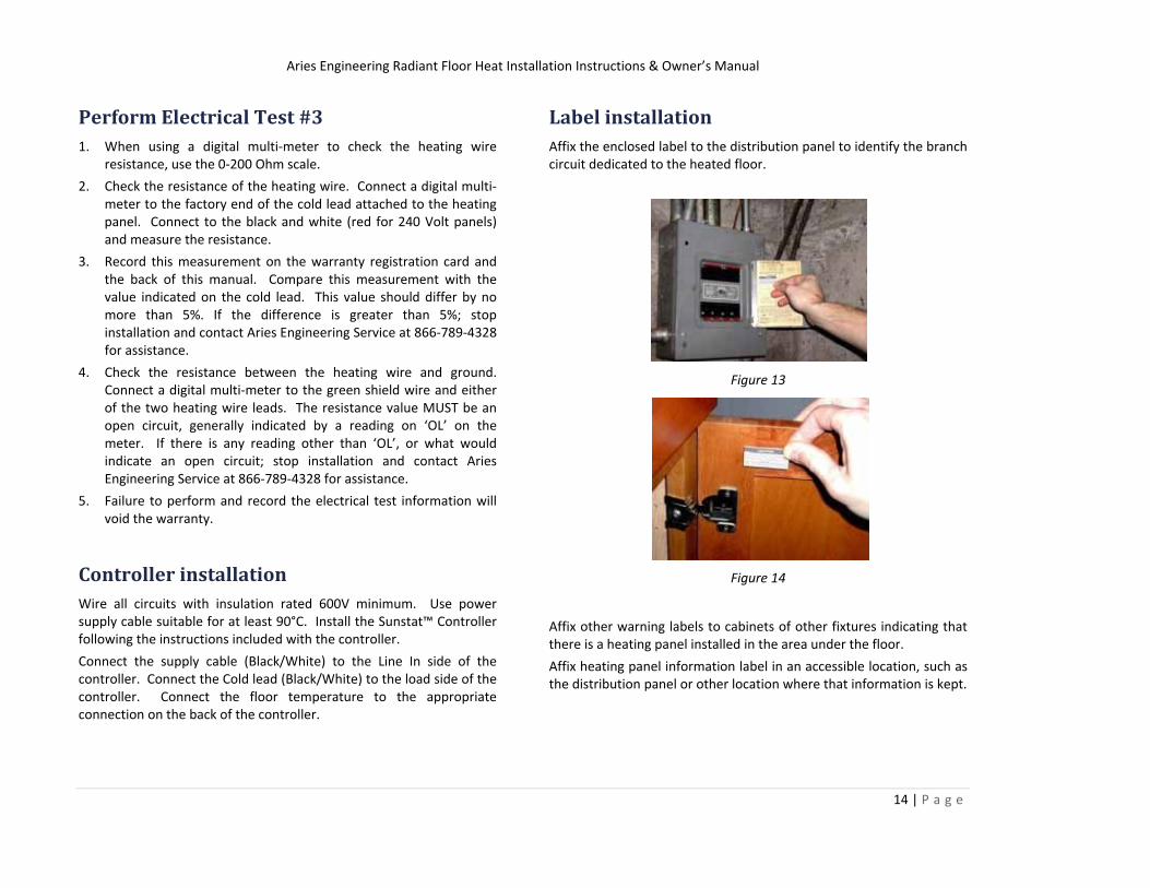
Label installation Affix the enclosed label to the distribution panel to identify the branch circuit dedicated to the heated floor.
Figure 13
Figure 14
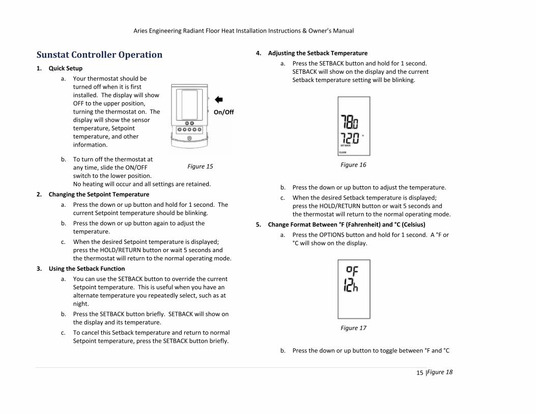
Affix other warning labels to cabinets of other fixtures indicating that there is a heating panel installed in the area under the floor.
Affix heating panel information label in an accessible location, such as the distribution panel or other location where that information is kept.
Aries Engineering Radiant Floor Heat Installation Instructions & Owner’s Manual
15 | P a g e
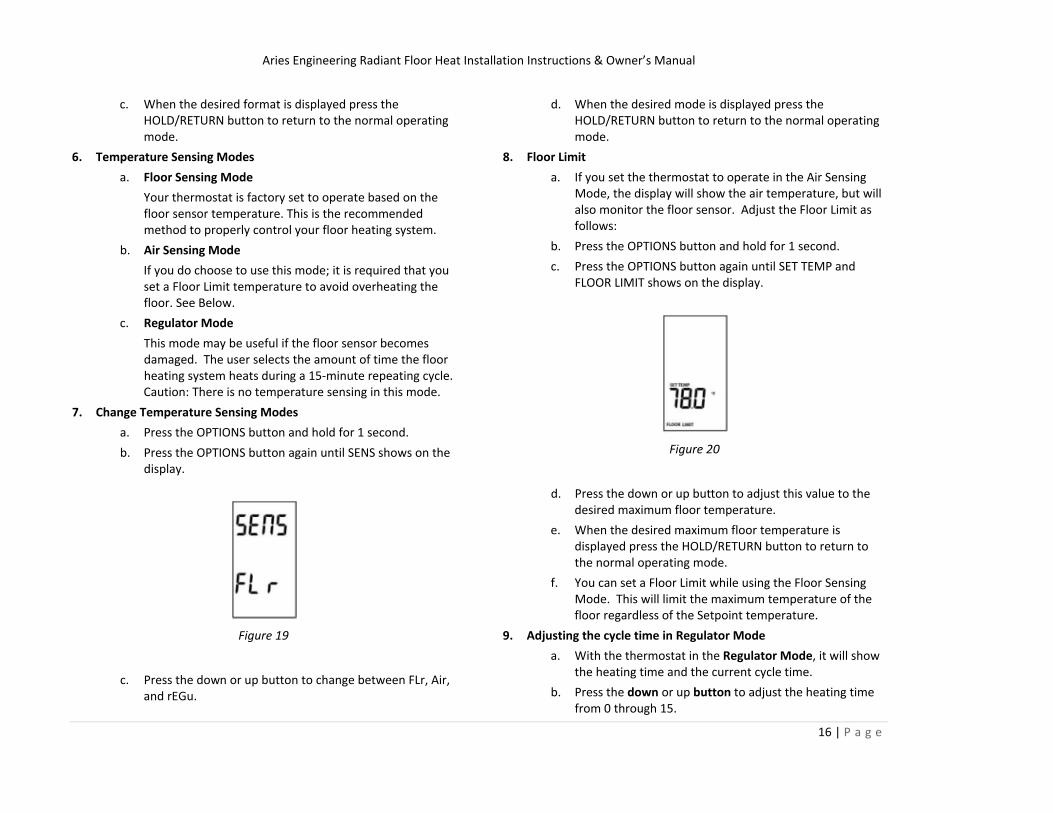
Sunstat Controller Operation 1. Quick Setup
a. Your thermostat should be turned off when it is first installed. The display will show OFF to the upper position, turning the thermostat on. The display will show the sensor temperature, Setpoint temperature, and other information.
b. To turn off the thermostat at any time, slide the ON/OFF switch to the lower position. No heating will occur and all settings are retained.
2. Changing the Setpoint Temperature
a. Press the down or up button and hold for 1 second. The current Setpoint temperature should be blinking.
b. Press the down or up button again to adjust the temperature.
c. When the desired Setpoint temperature is displayed; press the HOLD/RETURN button or wait 5 seconds and the thermostat will return to the normal operating mode.
3. Using the Setback Function
a. You can use the SETBACK button to override the current Setpoint temperature. This is useful when you have an alternate temperature you repeatedly select, such as at night.
b. Press the SETBACK button briefly. SETBACK will show on the display and its temperature.
c. To cancel this Setback temperature and return to normal Setpoint temperature, press the SETBACK button briefly.
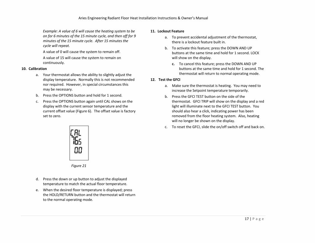
4. Adjusting the Setback Temperature
a. Press the SETBACK button and hold for 1 second. SETBACK will show on the display and the current Setback temperature setting will be blinking.
Figure 16
b. Press the down or up button to adjust the temperature.
c. When the desired Setback temperature is displayed; press the HOLD/RETURN button or wait 5 seconds and the thermostat will return to the normal operating mode.
5. Change Format Between °F (Fahrenheit) and °C (Celsius)
a. Press the OPTIONS button and hold for 1 second. A °F or °C will show on the display.
Figure 17
b. Press the down or up button to toggle between °F and °C
On/Off
Figure 18
Figure 15
Aries Engineering Radiant Floor Heat Installation Instructions & Owner’s Manual
16 | P a g e
c. When the desired format is displayed press the HOLD/RETURN button to return to the normal operating mode.
6. Temperature Sensing Modes
a. Floor Sensing Mode
Your thermostat is factory set to operate based on the floor sensor temperature. This is the recommended method to properly control your floor heating system.
b. Air Sensing Mode
If you do choose to use this mode; it is required that you set a Floor Limit temperature to avoid overheating the floor. See Below.
c. Regulator Mode
This mode may be useful if the floor sensor becomes damaged. The user selects the amount of time the floor heating system heats during a 15‐minute repeating cycle. Caution: There is no temperature sensing in this mode.
7. Change Temperature Sensing Modes
a. Press the OPTIONS button and hold for 1 second.
b. Press the OPTIONS button again until SENS shows on the display.
Figure 19
c. Press the down or up button to change between FLr, Air, and rEGu.
d. When the desired mode is displayed press the HOLD/RETURN button to return to the normal operating mode.
8. Floor Limit
a. If you set the thermostat to operate in the Air Sensing Mode, the display will show the air temperature, but will also monitor the floor sensor. Adjust the Floor Limit as follows:
b. Press the OPTIONS button and hold for 1 second.
c. Press the OPTIONS button again until SET TEMP and FLOOR LIMIT shows on the display.
Figure 20
d. Press the down or up button to adjust this value to the desired maximum floor temperature.
e. When the desired maximum floor temperature is displayed press the HOLD/RETURN button to return to the normal operating mode.
f. You can set a Floor Limit while using the Floor Sensing Mode. This will limit the maximum temperature of the floor regardless of the Setpoint temperature.
9. Adjusting the cycle time in Regulator Mode
a. With the thermostat in the Regulator Mode, it will show the heating time and the current cycle time.
b. Press the down or up button to adjust the heating time from 0 through 15.
Aries Engineering Radiant Floor Heat Installation Instructions & Owner’s Manual
17 | P a g e
Example: A value of 6 will cause the heating system to be on for 6 minutes of the 15 minute cycle, and then off for 9 minutes of the 15 minute cycle. After 15 minutes the cycle will repeat.
A value of 0 will cause the system to remain off.
A value of 15 will cause the system to remain on continuously.
10. Calibration a. Your thermostat allows the ability to slightly adjust the
display temperature. Normally this is not recommended nor required. However, in special circumstances this may be necessary.
b. Press the OPTIONS button and hold for 1 second.
c. Press the OPTIONS button again until CAL shows on the display with the current sensor temperature and the current offset value (Figure 6). The offset value is factory set to zero.
Figure 21
d. Press the down or up button to adjust the displayed temperature to match the actual floor temperature.
e. When the desired floor temperature is displayed; press the HOLD/RETURN button and the thermostat will return to the normal operating mode.
11. Lockout Feature a. To prevent accidental adjustment of the thermostat,
there is a lockout feature built in.
b. To activate this feature; press the DOWN AND UP buttons at the same time and hold for 1 second. LOCK will show on the display.
c. To cancel this feature; press the DOWN AND UP buttons at the same time and hold for 1 second. The thermostat will return to normal operating mode.
12. Test the GFCI a. Make sure the thermostat is heating. You may need to
increase the Setpoint temperature temporarily.
b. Press the GFCI TEST button on the side of the thermostat. GFCI TRIP will show on the display and a red light will illuminate next to the GFCI TEST button. You should also hear a click, indicating power has been removed from the floor heating system. Also, heating will no longer be shown on the display.
c. To reset the GFCI, slide the on/off switch off and back on.
Aries Engineering Radiant Floor Heat Installation Instructions & Owner’s Manual
18 | P a g e
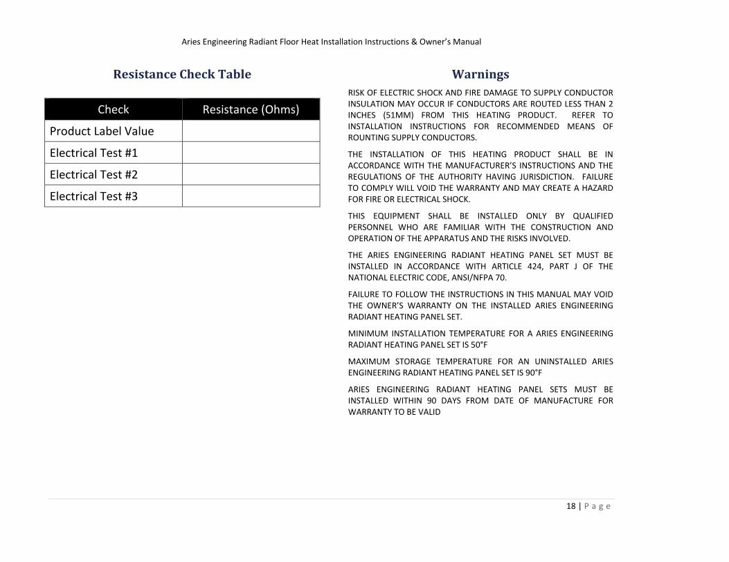
Resistance Check Table
Check Resistance (Ohms)
Product Label Value
Electrical Test #1
Electrical Test #2
Electrical Test #3
Warnings RISK OF ELECTRIC SHOCK AND FIRE DAMAGE TO SUPPLY CONDUCTOR INSULATION MAY OCCUR IF CONDUCTORS ARE ROUTED LESS THAN 2 INCHES (51MM) FROM THIS HEATING PRODUCT. REFER TO INSTALLATION INSTRUCTIONS FOR RECOMMENDED MEANS OF ROUNTING SUPPLY CONDUCTORS.
THE INSTALLATION OF THIS HEATING PRODUCT SHALL BE IN ACCORDANCE WITH THE MANUFACTURER’S INSTRUCTIONS AND THE REGULATIONS OF THE AUTHORITY HAVING JURISDICTION. FAILURE TO COMPLY WILL VOID THE WARRANTY AND MAY CREATE A HAZARD FOR FIRE OR ELECTRICAL SHOCK.
THIS EQUIPMENT SHALL BE INSTALLED ONLY BY QUALIFIED PERSONNEL WHO ARE FAMILIAR WITH THE CONSTRUCTION AND OPERATION OF THE APPARATUS AND THE RISKS INVOLVED.
THE ARIES ENGINEERING RADIANT HEATING PANEL SET MUST BE INSTALLED IN ACCORDANCE WITH ARTICLE 424, PART J OF THE NATIONAL ELECTRIC CODE, ANSI/NFPA 70.
FAILURE TO FOLLOW THE INSTRUCTIONS IN THIS MANUAL MAY VOID THE OWNER’S WARRANTY ON THE INSTALLED ARIES ENGINEERING RADIANT HEATING PANEL SET.
MINIMUM INSTALLATION TEMPERATURE FOR A ARIES ENGINEERING RADIANT HEATING PANEL SET IS 50°F
MAXIMUM STORAGE TEMPERATURE FOR AN UNINSTALLED ARIES ENGINEERING RADIANT HEATING PANEL SET IS 90°F
ARIES ENGINEERING RADIANT HEATING PANEL SETS MUST BE INSTALLED WITHIN 90 DAYS FROM DATE OF MANUFACTURE FOR WARRANTY TO BE VALID
Aries Engineering Radiant Floor Heat Installation Instructions & Owner’s Manual
19 | P a g e
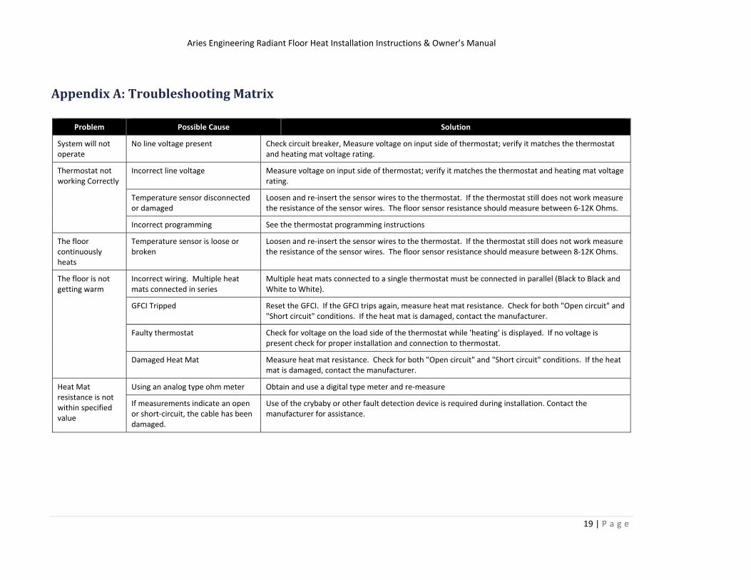
Appendix A: Troubleshooting Matrix
Problem Possible Cause Solution
System will not operate
No line voltage present Check circuit breaker, Measure voltage on input side of thermostat; verify it matches the thermostat and heating mat voltage rating.
Thermostat not working Correctly
Incorrect line voltage Measure voltage on input side of thermostat; verify it matches the thermostat and heating mat voltage rating.
Temperature sensor disconnected or damaged
Loosen and re‐insert the sensor wires to the thermostat. If the thermostat still does not work measure the resistance of the sensor wires. The floor sensor resistance should measure between 6‐12K Ohms.
Incorrect programming See the thermostat programming instructions
The floor continuously heats
Temperature sensor is loose or broken
Loosen and re‐insert the sensor wires to the thermostat. If the thermostat still does not work measure the resistance of the sensor wires. The floor sensor resistance should measure between 8‐12K Ohms.
The floor is not getting warm
Incorrect wiring. Multiple heat mats connected in series
Multiple heat mats connected to a single thermostat must be connected in parallel (Black to Black and White to White).
GFCI Tripped Reset the GFCI. If the GFCI trips again, measure heat mat resistance. Check for both "Open circuit" and "Short circuit" conditions. If the heat mat is damaged, contact the manufacturer.
Faulty thermostat Check for voltage on the load side of the thermostat while 'heating' is displayed. If no voltage is present check for proper installation and connection to thermostat.
Damaged Heat Mat Measure heat mat resistance. Check for both "Open circuit" and "Short circuit" conditions. If the heat mat is damaged, contact the manufacturer.
Heat Mat resistance is not within specified value
Using an analog type ohm meter Obtain and use a digital type meter and re‐measure
If measurements indicate an open or short‐circuit, the cable has been damaged.
Use of the crybaby or other fault detection device is required during installation. Contact the manufacturer for assistance.
Aries Engineering Radiant Floor Heat Installation Instructions & Owner’s Manual
20 | P a g e
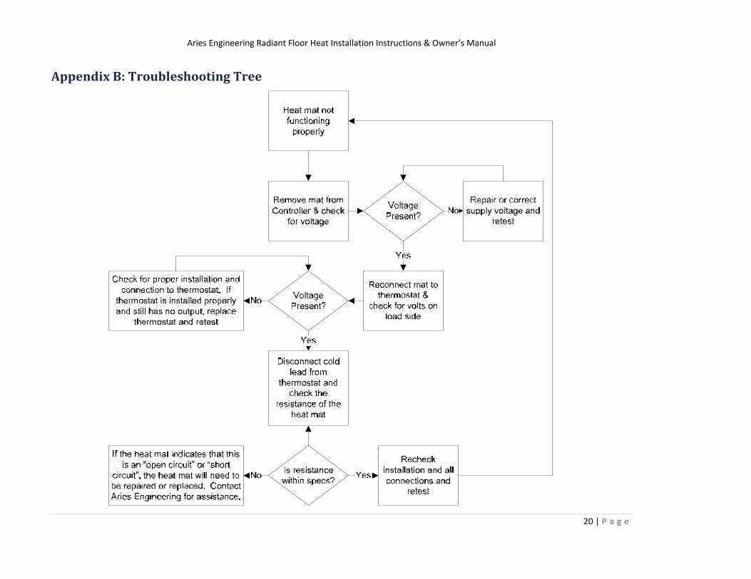
Appendix B: Troubleshooting Tree


![Radiant Floor Cooling Systems[1]](https://img.pdfslide.us/doc/110x75/5514c6bc497959f81d8b4975/radiant-floor-cooling-systems1.jpg)