Embed Size (px)
Citation preview
WARNINGThe operator of this instrument is advised that if equipment is used in a manner not specified in this manual, the protection provided by the equipment may be impaired.
Failure to comply with these instructions could result in death or serious injury.
WARNINGPERSONAL INJURYDO NOT use these devices as safety or emergency stop devices, or in any other application where failure of the product could result in personal injury.
Failure to comply with these instructions could result in death or serious injury.
CAUTIONOnly qualified, service-trained personnel who are aware of the hazards involved should remove the cover from the instrument or connect external wiring to the instrument.
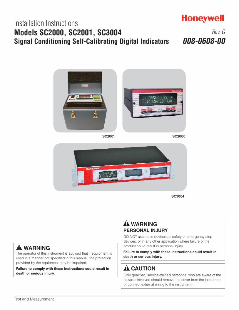
Installation InstructionsModels SC2000, SC2001, SC3004Signal Conditioning Self-Calibrating Digital Indicators
Test and Measurement
Rev. G
008-0608-00
SC2001 SC2000
SC3004
ii Honeywell Sensing and Control
Signal Conditioning, Self Calibrating Digital Indicators Rev. G, 008-0608-00
Table of Contents
Chapter 1 - Introduction. . . . . . . . . . . . . . . . . . 11.1 About this manual. . . . . . . . . . . . . . . . . .1
1.1.1 Scope . . . . . . . . . . . . . . . . . . . . . .11.1.2 Conventions . . . . . . . . . . . . . . . . . . .11.1.3 Organization . . . . . . . . . . . . . . . . . .1
1.2 Related Documents . . . . . . . . . . . . . . . . .2Customer Information Sheet. . . . . . . . . . . . . .2Communications Guide. . . . . . . . . . . . . . . .2Supplemental Instructions . . . . . . . . . . . . . .2
1.3 What is the SC Series? . . . . . . . . . . . . . . .21.3.1 Features . . . . . . . . . . . . . . . . . . . . .21.3.2 Chassis Models. . . . . . . . . . . . . . . . .21.3.3 Channel Types. . . . . . . . . . . . . . . . . .2
1.4 What is Signature Calibration? . . . . . . . . . . .31.4.1 Overview . . . . . . . . . . . . . . . . . . . .31.4.2 Benefits . . . . . . . . . . . . . . . . . . . . .31.4.3. Information Stored . . . . . . . . . . . . . . .3
Chapter 2 Getting Started Quickly . . . . . . . . . 42.1 Locate Required Parts and Information . . . . . . .42.2 Connect Transducer to the Correct Channel . . . .42.3 Turn on the Instrument . . . . . . . . . . . . . . .42.4 Use the SETUP Menus to Enter Information . . . .52.5 Calibrate the Transducers to Their Channels . . . .52.6 The SC Series Instrument is Ready for Use . . . . .5
Chapter 3 Operating Modes. . . . . . . . . . . . . . . 63.1 Operating Modes . . . . . . . . . . . . . . . . . .63.2 INITIALIZE Mode. . . . . . . . . . . . . . . . . . .63.3 RUN Mode. . . . . . . . . . . . . . . . . . . . . .6
3.3.1 Display. . . . . . . . . . . . . . . . . . . . . .63.3.2 [VALUE] button . . . . . . . . . . . . . . . . .63.3.3 [CLEAR] Button . . . . . . . . . . . . . . . . .73.3.4 [CHANNEL] button. . . . . . . . . . . . . . .73.3.5 [TARE] button . . . . . . . . . . . . . . . . . .73.3.6 Indicator Lights . . . . . . . . . . . . . . . . .7
3.4 ERROR mode. . . . . . . . . . . . . . . . . . . . .73.5 SETUP Menu mode . . . . . . . . . . . . . . . . .7
3.5.1 Available Menus. . . . . . . . . . . . . . . . .73.5.2 Entering and Exiting the SETUP Menu mode. .73.5.3 Moving Through SETUP Menus . . . . . . . . .83.5.4 Exiting the SETUP Menu mode . . . . . . . . .8
Chapter 4 Chassis Models. . . . . . . . . . . . . . . . 94.1 Introduction . . . . . . . . . . . . . . . . . . . . .94.2 Specifications . . . . . . . . . . . . . . . . . . . .9
4.3 Model SC2000. . . . . . . . . . . . . . . . . . . 104.3.1 External Arrangement . . . . . . . . . . . . . 104.3.2 Rear Panel . . . . . . . . . . . . . . . . . . 114.3.3 Panel Mounting . . . . . . . . . . . . . . . . 114.3.4 Rack Mounting . . . . . . . . . . . . . . . . 114.3.5 Bench Mounting . . . . . . . . . . . . . . . . 114.3.6 Case Removal . . . . . . . . . . . . . . . . . 114.3.7 Internal Arrangement . . . . . . . . . . . . . 124.3.8 Cleaning . . . . . . . . . . . . . . . . . . . . 124.3.9 Vehicle Power Option . . . . . . . . . . . . . 124.3.10 Fuse Replacement . . . . . . . . . . . . . . 12
4.4 Model SC2001. . . . . . . . . . . . . . . . . . . 124.4.1 Differences . . . . . . . . . . . . . . . . . . 134.4.2 External Arrangement . . . . . . . . . . . . 134.4.3 Front Panel . . . . . . . . . . . . . . . . . . 134.4.4 Case Removal . . . . . . . . . . . . . . . . 144.4.5 Internal Arrangement . . . . . . . . . . . . . 144.4.6 Cleaning . . . . . . . . . . . . . . . . . . . . 144.4.7 Vehicle Power Option . . . . . . . . . . . . . 144.4.8 Fuse Replacement. . . . . . . . . . . . . . . 14
4.5 Model SC3004. . . . . . . . . . . . . . . . . . . 154.5.1 External Arrangement . . . . . . . . . . . . . 154.5.2 Rear Panel. . . . . . . . . . . . . . . . . . . 154.5.3. Panel Mounting . . . . . . . . . . . . . . . 154.5.4 Bench Mounting . . . . . . . . . . . . . . . . 154.5.5 Case Removal . . . . . . . . . . . . . . . . . 154.5.6 Rear Panel . . . . . . . . . . . . . . . . . . 164.5.7 Internal Arrangement . . . . . . . . . . . . . 164.5.8 Cleaning . . . . . . . . . . . . . . . . . . . 164.5.9 Fuse Replacement. . . . . . . . . . . . . . . 16
Chapter 5 System Connector. . . . . . . . . . . . . 175.1 Introduction . . . . . . . . . . . . . . . . . . . . 175.3 Function Input Pins . . . . . . . . . . . . . . . . 18
5.3.1 Overview . . . . . . . . . . . . . . . . . . . 185.3.2. Example . . . . . . . . . . . . . . . . . . . 18
5.4 Limit Output Pins . . . . . . . . . . . . . . . . . 185.4.1 Overview . . . . . . . . . . . . . . . . . . . 185.4.2 Example . . . . . . . . . . . . . . . . . . . . 18
Chapter 6 System Menu . . . . . . . . . . . . . . . . 196.1 Overview . . . . . . . . . . . . . . . . . . . . . 196.2 Menu Items . . . . . . . . . . . . . . . . . . . . 19
6.2.1 SOFTWARE REVISION Menu Item. . . . . . . 196.2.2 CONFIGURATION Sub-Menu . . . . . . . . . 196.2.3 DIAGNOSTICS Sub-Menu . . . . . . . . . . 196.2.4 INSTALL CHANNEL Menu Item . . . . . . . . 196.2.5 DELETE CHANNEL Menu Item . . . . . . . . 206.2.6 DEFAULT CHANNEL Menu Item. . . . . . . . 20
Honeywell Sensing and Control iii
SC 2000, SC2001, SC3004 Rev. G, 008-0608-00Chapter 7 Serial Communications . . . . . . . . 21
7.1 Overview . . . . . . . . . . . . . . . . . . . . . 217.2 Wiring . . . . . . . . . . . . . . . . . . . . . . . 217.3 Communications Protocol. . . . . . . . . . . . . 21
7.3.1 RS-232 vs. RS-485 . . . . . . . . . . . . . . 217.3.2 Parameters . . . . . . . . . . . . . . . . . . 21
7.4 Serial Com Menu . . . . . . . . . . . . . . . . . 217.4.1 Overview . . . . . . . . . . . . . . . . . . . 217.4.2 INTERFACE Menu Item . . . . . . . . . . . . 217.4.3. ADDRESS Menu Item . . . . . . . . . . . . 217.4.4. BAUD RATE Menu Item. . . . . . . . . . . . 217.4.5 AUTO LINE-FEED Menu Item . . . . . . . . . 217.4.6 TRANSMIT TEST Menu Item . . . . . . . . . 227.4.7 LEAVE MENU Menu Item . . . . . . . . . . . 22
Chapter 8 Display Menu . . . . . . . . . . . . . . . . 238.1 Overview . . . . . . . . . . . . . . . . . . . . . 238.2 Menu Items for Models SC2000, SC2001 . . . . . 23
8.2.1 UPPER CHANNEL Menu Item . . . . . . . . 238.2.2 LOWER CHANNEL Menu Item . . . . . . . . 238.2.3 LOWER MODE Menu Item . . . . . . . . . . 238.2.4 DISPLAY DISABLE Menu Item . . . . . . . . 23
8.3 Menu Items for Model SC3004 . . . . . . . . . . 238.3.1 POWER-ON CHANNEL Menu Item . . . . . . 23
Chapter 9 Limits . . . . . . . . . . . . . . . . . . . . . . 249.1 Limits, Set Points and Return Points . . . . . . . 249.2 Limit Operation . . . . . . . . . . . . . . . . . . 24
9.2.1 Actions When Activated . . . . . . . . . . . 249.2.2 Scan Time. . . . . . . . . . . . . . . . . . . 24
9.3 Limit Menus . . . . . . . . . . . . . . . . . . . . 249.3.1 Overview. . . . . . . . . . . . . . . . . . . . 249.3.2 LIMIT.ENABLE Menu Item . . . . . . . . . . . 249.3.3 LIMIT.SETPOINT Menu Item . . . . . . . . . 249.3.4 LIMIT.RETURN PNT Menu Item . . . . . . . . 259.3.5 LIMIT.ENERGIZE Menu Item . . . . . . . . . 259.3.6 LIMIT.LATCHING Menu Item . . . . . . . . . 269.3.7 LIMIT.CHANNEL Menu Item . . . . . . . . . 269.3.8 LIMIT.SOURCE Menu Item . . . . . . . . . . 269.3.9 LEAVE MENU Menu Item . . . . . . . . . . . 26
Chapter 10 Strain-Gage Input Channel . . . . 2610.1 Features . . . . . . . . . . . . . . . . . . . . . 2610.2 Wiring . . . . . . . . . . . . . . . . . . . . . . 2710.3 Calibration Procedure . . . . . . . . . . . . . . 2810.4 Specifications . . . . . . . . . . . . . . . . . . 2810.5 Channel Menu . . . . . . . . . . . . . . . . . . 29
10.5.1 OPERATION Sub-Menu. . . . . . . . . . . . 29
10.5.2 DISPLAY SETUP Sub-Menu . . . . . . . . . 2910.5.3 AUXn FUNCTION Menu Items . . . . . . . . 3010.5.4 CALIBRATION TYPE Menu Item . . . . . . . 3110.5.5 CALIBRATION DATA Sub-Menu . . . . . . . 3210.5.6 CALIBRATE Menu Item . . . . . . . . . . . 3310.5.7 DAC SETUP Sub-Menu. . . . . . . . . . . . 3410.5.8 SIGNATURE MODULE Sub-Menu . . . . . . 3510.5.9 DIAGNOSTICS Sub-Menu . . . . . . . . . . 36
10.6 Analog Output Configuration . . . . . . . . . . 3610.6.1 Identifying the Output Type . . . . . . . . . 3610.6.2 Channel Menu Items . . . . . . . . . . . . . 3610.6.3. Output Selection . . . . . . . . . . . . . . 36
10.7 Troubleshooting . . . . . . . . . . . . . . . . . 3710.7.1 Error Messages . . . . . . . . . . . . . . . 3710.7.2 Common Problems and Solutions . . . . . . 37
Chapter 11 AC/AC-LVDT Input Channel . . . . 3911.1 Features . . . . . . . . . . . . . . . . . . . . . 3911.2 Wiring . . . . . . . . . . . . . . . . . . . . . . 3911.3 Calibration Procedure . . . . . . . . . . . . . . 4011.4 Specifications . . . . . . . . . . . . . . . . . . 4011.5 Channel Menu . . . . . . . . . . . . . . . . . . 41
11.5.1 OPERATION Sub-Menu. . . . . . . . . . . . 4111.5.2 DISPLAY SETUP Sub-Menu . . . . . . . . . 4111.5.3 AUXn FUNCTION Menu Items . . . . . . . . 4211.5.4 CALIBRATION TYPE Menu Item . . . . . . . 4211.5.5. CALIBRATION DATA Sub-Menu . . . . . . 4211.5.6 CALIBRATE Menu Item . . . . . . . . . . . 4311.5.7 DAC SETUP Sub-Menu . . . . . . . . . . . 4411.5.8 DIAGNOSTICS Sub-Menu . . . . . . . . . . 44
11.6 Electrical Null and Transducer Mounting . . . . 4511.6.1 Overview . . . . . . . . . . . . . . . . . . . 45
11.7 Analog Output Configuration . . . . . . . . . . 4611.7.1 Identifying the Output Type. . . . . . . . . . 4611.7.2 Channel Menu Items . . . . . . . . . . . . . 4611.7.3 Output Selection . . . . . . . . . . . . . . . 46
11.8 Troubleshooting . . . . . . . . . . . . . . . . . 4711.8.1 Error Messages. . . . . . . . . . . . . . . . 4711.8.2 Common Problems and Solutions . . . . . . 47
Chapter 12 High-Level Input Channel . . . . . 4812.1 Features . . . . . . . . . . . . . . . . . . . . . 4812.2 Wiring . . . . . . . . . . . . . . . . . . . . . . 48
12.2.1 Channel Connector . . . . . . . . . . . . . 4812.2.2 Bi-polar Voltage Amplifiers . . . . . . . . . 4912.2.3 “3-wire Voltage” Amplifiers. . . . . . . . . . 5012.2.4 “3-wire Voltage” Amps with 1-wire Shunt Cal.5112.2.5 3-wire Current” Amplifier . . . . . . . . . . . 52
iv Honeywell Sensing and Control
Signal Conditioning, Self Calibrating Digital Indicators Rev. G, 008-0608-0012.2.6 “2-wire Current” Amps Buff. Shunt Cal . . . 5312.2.7 “2-wire Current” Amps 1-wire Shunt Cal . . . 5412.2.8 Low Voltage dc-dc LVDTs . . . . . . . . . . 55
12.3 Excitation and Signal Jumpers. . . . . . . . . . 5612.3.1 Overview . . . . . . . . . . . . . . . . . . . 5612.3.2 Setting Jumpers . . . . . . . . . . . . . . . 56
12.4 Calibration Procedure . . . . . . . . . . . . . . 5612.5 Specifications . . . . . . . . . . . . . . . . . . 5712.6 Channel Menu. . . . . . . . . . . . . . . . . . . 57
12.6.1 OPERATION Sub-Menu . . . . . . . . . . . 5712.6.2 DISPLAY SETUP Sub-Menu . . . . . . . . . 5812.6.3 AUXn FUNCTION Menu Items . . . . . . . . 5912.6.4 CALIBRATION TYPE Menu Item . . . . . . . 5912.6.5 CALIBRATION DATA Sub-Menu. . . . . . . 6012.6.6 CALIBRATE Menu Item . . . . . . . . . . . 6112.6.7 DAC SETUP Sub-Menu. . . . . . . . . . . . 6212.6.8 DIAGNOSTICS Sub-Menu. . . . . . . . . . 63
12.7 Analog Output Configuration . . . . . . . . . . 6312.7.1 Identifying the Output Type . . . . . . . . . 6312.7.2 Channel Menu Items . . . . . . . . . . . . . 6312.7.3 Output Selection . . . . . . . . . . . . . . . 63
12.8 Troubleshooting . . . . . . . . . . . . . . . . . 6412.8.1 Error Messages. . . . . . . . . . . . . . . . 6412.8.2. Common Problems and Solutions . . . . . . 64
Chapter 13 Relay Output Channel. . . . . . 6513.1 Features . . . . . . . . . . . . . . . . . . . . . 65
13.1.1 First Channel Installed . . . . . . . . . . . . 6513.1.2 Second Channel Installed . . . . . . . . . . 6513.1.3 Third Channel Installed. . . . . . . . . . . . 6513.1.4 Fourth Channel Installed . . . . . . . . . . . 65
13.2 Wiring . . . . . . . . . . . . . . . . . . . . . . 6513.3 Setup Procedure . . . . . . . . . . . . . . . . . 6513.4 Specifications. . . . . . . . . . . . . . . . . . . 6513.5 Channel Menu . . . . . . . . . . . . . . . . . . 66
13.5.1 DIAGNOSTICS Sub-Menu . . . . . . . . . . 66
Chapter 14 DAC Output Channel . . . . . . . . . 6614.1 Features . . . . . . . . . . . . . . . . . . . . . 6614.2 Wiring . . . . . . . . . . . . . . . . . . . . . . 6614.3 Setup Procedure . . . . . . . . . . . . . . . . . 6714.4 Specifications . . . . . . . . . . . . . . . . . . 6714.5 Channel Menu . . . . . . . . . . . . . . . . . . 67
14.5.1 DAC SETUP Sub-Menu. . . . . . . . . . . . 6714.5.2 DIAGNOSTICS Sub-Menu. . . . . . . . . . 68
14.6 Analog Output Configuration . . . . . . . . . . 6814.6.1 Identifying the Output Type . . . . . . . . . 6814.6.2 Channel Menu Items . . . . . . . . . . . . . 6814.6.3 Output Selection . . . . . . . . . . . . . . . 68
14.7 Troubleshooting. . . . . . . . . . . . . . . . . . 6914.7.1 Error Messages . . . . . . . . . . . . . . . 6914.7.2 Common Problems and Solutions . . . . . . 69
Chapter 15 Split Display Virtual Channel. . . 7015.1 Features . . . . . . . . . . . . . . . . . . . . . 7015.2 Wiring . . . . . . . . . . . . . . . . . . . . . . 7015.3 Setup Procedure. . . . . . . . . . . . . . . . . 7015.4 Channel Menu . . . . . . . . . . . . . . . . . . 7015.5 Troubleshooting . . . . . . . . . . . . . . . . . 70
Chapter 16 Mathematics Virtual Channel . . 7116.1 Features . . . . . . . . . . . . . . . . . . . . . 7116.2 Wiring . . . . . . . . . . . . . . . . . . . . . . 7116.3 Setup Procedure . . . . . . . . . . . . . . . . . 7116.4 Channel Menu. . . . . . . . . . . . . . . . . . . 71
16.4.5 DISPLAY SETUP Sub-Menu . . . . . . . . . 7216.4.6 POWER-ON SOURCE Menu Item . . . . . . 72
16.5 Troubleshooting . . . . . . . . . . . . . . . . . 72
Chapter 17 Error Messages . . . . . . . . . . . . . 7317.1 Overview . . . . . . . . . . . . . . . . . . . . . 7317.2 Error Message List . . . . . . . . . . . . . . . . 73
Chapter 18 Setup Menu Reference . . . . . . . . 7718.1 Navigation Instructions. . . . . . . . . . . . . . 77
Honeywell Sensing and Control v
SC 2000, SC2001, SC3004 Rev. G, 008-0608-00
FiguresFigure 4-1: External Arrangement of ac powered SC2000 . . . . . . . . . . . . . . . . . . . . . . . . . . . . . . 10Figure 4-2: Panel Cutout Drawing for SC2000 (not to scale) . . . . . . . . . . . . . . . . . . . . . . . . . . . . . 11Figure 4-3: Internal Arrangement of SC2000 . . . . . . . . . . . . . . . . . . . . . . . . . . . . . . . . . . . . . 12Figure 4-4: External Arrangement of AC powered Model SC2001 . . . . . . . . . . . . . . . . . . . . . . . . . . 13Figure 4-5: External Arrangement of Model SC3004 . . . . . . . . . . . . . . . . . . . . . . . . . . . . . . . . . 15Figure 5-1: Function Input Example . . . . . . . . . . . . . . . . . . . . . . . . . . . . . . . . . . . . . . . . . . 18Figure 5-2: Open-Collector Output Example . . . . . . . . . . . . . . . . . . . . . . . . . . . . . . . . . . . . . 18Figure 6-1: Address Jumper Block Location . . . . . . . . . . . . . . . . . . . . . . . . . . . . . . . . . . . . . 19Figure 6-2: Address Jumper Settings . . . . . . . . . . . . . . . . . . . . . . . . . . . . . . . . . . . . . . . . . 20Figure 9-1: Limit Operation when LIMIT.ENERGIZE = SIGNAL > SETPOINT . . . . . . . . . . . . . . . . . . . . . 25Figure 9-2: Limit Operation when LIMIT.ENERGIZE = SIGNAL < SETPOINT . . . . . . . . . . . . . . . . . . . . . 25Figure 9-3: Limit Operation when LIMIT.ENERGIZE = SIGNAL INSIDE . . . . . . . . . . . . . . . . . . . . . . . . 25Figure 9-4: Limit Operation when LIMIT.ENERGIZE = SIGNAL OUTSIDE . . . . . . . . . . . . . . . . . . . . . . 25Figure 10-1: Unamplified Transducer Connection to Strain-Gage Input Channel . . . . . . . . . . . . . . . . . . 27Figure 10-2: Shunt Calibration Resistor Location . . . . . . . . . . . . . . . . . . . . . . . . . . . . . . . . . . . 33Figure 10-3: Digital-to-Analog Output Jumper Locations . . . . . . . . . . . . . . . . . . . . . . . . . . . . . . . 37Figure 11-2: Digital-to-Analog Output Jumper Locations . . . . . . . . . . . . . . . . . . . . . . . . . . . . . . . 46Figure 12-1: “Bi-polar Voltage Amp” Connection to High-Level Input Channel . . . . . . . . . . . . . . . . . . . . 49Figure 12-2: “3-wire Voltage Amp” Connection to High-Level Input Channel . . . . . . . . . . . . . . . . . . . . 50Figure 12-3: “3-wire Voltage Amp w/Single-Wire Shunt Cal” Connection to High-Level Input Channel . . . . . . . 51Figure 12-4: “3-wire Current Amp” Connection to High-Level Input Channel . . . . . . . . . . . . . . . . . . . . . 52Figure 12-5: “2-wire Current Amp w/Buffered Shunt Cal” Connection to High-Level Input Channel . . . . . . . . . 53Figure 12-6: “2-wire Current Amp w/Single-Wire Shunt Cal” Connection to High-Level Input Channel . . . . . . . 54Figure 12-7: “Low Voltage” dc-dc LVDT Connection to High-Level Input Channel . . . . . . . . . . . . . . . . . . 55Figure 12-8: Excitation and Signal Jumper Locations on the High-Level Input Channel . . . . . . . . . . . . . . . 56Figure 12-9: Digital-to-Analog Output Jumper Locations . . . . . . . . . . . . . . . . . . . . . . . . . . . . . . . 64Figure 14-1: Digital-to-Analog Output Jumper Locations . . . . . . . . . . . . . . . . . . . . . . . . . . . . . . . 68
vi Honeywell Sensing and Control
Signal Conditioning, Self Calibrating Digital Indicators Rev. G, 008-0608-00
TablesTable 3-1: Navigating the Menus . . . . . . . . . . . . . . . . . . . . . . . . . . . . . . . . . . . . . . . . . . . . 8Table 5-2: System Connector . . . . . . . . . . . . . . . . . . . . . . . . . . . . . . . . . . . . . . . . . . . . . 17Table 10-1: Strain Gage Input Channel Pin Connectors . . . . . . . . . . . . . . . . . . . . . . . . . . . . . . . 27Table 10-: Comparison of Calibration Types . . . . . . . . . . . . . . . . . . . . . . . . . . . . . . . . . . . . . 31Table 11-1: ac/ac-LVDT Input Channel Pin Connections . . . . . . . . . . . . . . . . . . . . . . . . . . . . . . . 39Table 12-1: High-Level Input Channel Pin Connections . . . . . . . . . . . . . . . . . . . . . . . . . . . . . . . 48Table 12-2: Comparison of Calibration Types . . . . . . . . . . . . . . . . . . . . . . . . . . . . . . . . . . . . . 59Table 13-1 Relay Output Channel Pin Connections . . . . . . . . . . . . . . . . . . . . . . . . . . . . . . . . . . 65Table 14-1: DAC Output Channel Pin Connections . . . . . . . . . . . . . . . . . . . . . . . . . . . . . . . . . . 66Table 18-1: SETUP Menu . . . . . . . . . . . . . . . . . . . . . . . . . . . . . . . . . . . . . . . . . . . . . . . 77Table 18-2: System Menu . . . . . . . . . . . . . . . . . . . . . . . . . . . . . . . . . . . . . . . . . . . . . . . 78Table 18-3: LIMIT Menu . . . . . . . . . . . . . . . . . . . . . . . . . . . . . . . . . . . . . . . . . . . . . . . . 79Table 18-4: SERIAL COMMUNICATIONS Menu . . . . . . . . . . . . . . . . . . . . . . . . . . . . . . . . . . . 79Table 18-5: DISPLAY Menu for Models SC2000, SC2001 . . . . . . . . . . . . . . . . . . . . . . . . . . . . . . . 79Table 18-6: Display Menu for Model SC3004 . . . . . . . . . . . . . . . . . . . . . . . . . . . . . . . . . . . . . 79Table 18-7: Strain Gage Input Channel Menu . . . . . . . . . . . . . . . . . . . . . . . . . . . . . . . . . . . . . 80Table 18-7: Strain Gage Input Channel Menu, continued . . . . . . . . . . . . . . . . . . . . . . . . . . . . . . . 81Table 18-8: ac-ac LVDT Input Channel Menu . . . . . . . . . . . . . . . . . . . . . . . . . . . . . . . . . . . . . 82Table 18-8: ac-ac LVDT Input Channel Menu, continued . . . . . . . . . . . . . . . . . . . . . . . . . . . . . . . 83Table 18-9: High Level Input Channel Menu . . . . . . . . . . . . . . . . . . . . . . . . . . . . . . . . . . . . . 84Table 18-9: High Level Input Channel Menu, continued . . . . . . . . . . . . . . . . . . . . . . . . . . . . . . . 85Table 18-10: Relay Output Channel . . . . . . . . . . . . . . . . . . . . . . . . . . . . . . . . . . . . . . . . . . 86Table 18-11: DAC Output Channel Menu . . . . . . . . . . . . . . . . . . . . . . . . . . . . . . . . . . . . . . . 86Table 18-12: Split Display Virtual Channel . . . . . . . . . . . . . . . . . . . . . . . . . . . . . . . . . . . . . . 86Table 18-13: Mathematics Virtual Channel . . . . . . . . . . . . . . . . . . . . . . . . . . . . . . . . . . . . . . 87
Honeywell Sensing and Control 1
SC 2000, SC2001, SC3004 Rev. G, 008-0608-00
Chapter 9, “Limits”, discusses how the limits operate and de-scribes how to alter their settings via the Limit Menus.
Chapter 10, “Strain-Gage Input Channel”, explains how to wire, configure, operate and calibrate Strain-Gage Input Channels with your transducers.
Chapter 11, “AC/AC-LVDT Input Channel”, explains how to wire, configure, operate and calibrate AC/AC-LVDT Input Channels with your transducers.
Chapter 12, “High-Level Input Channel”, explains how to wire, configure, operate and calibrate High-Level Input Channels with your amplified transducers, in-line amplifiers, or dc-dc LVDTs.
Chapter 13, “Relay Output Channel”, describes how a Relay Output channel can enable additional limits in the instrument.
Chapter 14, “DAC Output Channel”, explains the configuration and operation of additional digital-to-analog voltage or current outputs.
Chapter 15, “Split Display Virtual Channel”, shows how you can display two values from any of the channels in the instrument at the same time.
Chapter 16, “Mathematics Virtual Channel”, describes the flex-ibility of customer-specific SensoCode programming.
Chapter 17, “Error Messages”, lists error messages that the instrument may display, describes their causes and, where pos-sible, suggests solutions.
Chapter 18, “Setup Menu Reference”, is a list of all SETUP menus and a cross-reference to related information in this instruc-tion manual.
Chapter 1 - Introduction
1.1 About this manual
1.1.1 ScopeThis manual will explain the setup, features and operation of 3rd generation SC Series instruments, specifically the models SC2000, SC2001 and SC3004.
Further information about customer specific programming and setup will be explained on the Customer Information Sheet that is provided with every instrument.
1.1.2 ConventionsThis manual uses the following conventions to present informa-tion:
[TEXT IN BRACKETS] The label of a front panel button.
DISPLAY Text that appears on the display, such as error messages or menu items.
-> Indicates that what follows is an item from a sub-menu, such as SYSTEM MENU -> DIAGNOSTICS.
1.1.3 OrganizationChapter 1, “Introduction”, offers general information about the SC Series and this instruction manual.
Chapter 2, “Getting Started Quickly”, provides an overview of how to get started quickly if your instrument and transducers were ordered at the same time, or if Signature Calibration is used.
Chapter 3, “Operating Modes”, discusses the significant fea-tures of the SC Series and operation procedures when the instru-ment is in the INITIALIZE, RUN, ERROR or SETUP modes.
Chapter 4, “Chassis Models”, explains the differences between the SC2000, SC2001 and SC3004 chassis. Information relating to the hardware chassis such as panel and rack mounting is given.
Chapter 5, “System Connector”, contains information about wir-ing to the 25-pin System connector to access the Limit Outputs, Function Inputs and serial communications.
Chapter 6, “System Menu”, discusses the System Menu which allows you to examine and change settings that affect the opera-tion of the chassis.
Chapter 7, “Serial Communications”, briefly describes RS-232 and RS-485 communications. It also shows how to use the SE-RIAL COM Menu to examine the settings and test the RS-232 or RS-485 communications.
Chapter 8, “Display Menu”, describes the Display Menu which allows you to change what is displayed on the lower line of the SC2000 and SC2001 instruments.
2 Honeywell Sensing and Control
Signal Conditioning, Self Calibrating Digital Indicators Rev. G, 008-0608-00
1.2 Related DocumentsCustomer Information SheetEvery instrument is shipped with a Customer Information Sheet which documents important information specific to each instru-ment, such as:
• Partnumber,• Dateofmanufacture,• Listofallinstalledchannelsandtheirsetupinformation,• CustomerspecificSensoCodeprogrammingofMathematics
Virtual channels and operation notes.Communications GuideThe “SC Series Communications Guide”, document 008-0610-00, describes in detail how to communicate with an SC Series instrument using RS-232 and RS-485. Wiring diagrams, sample programs, and descriptions of each command are included.
A printed copy of this document is available for order, or you may download it from http://measurementsensors.honeywell.com.
Supplemental InstructionsIf an instrument is configured with Mathematics Virtual channels, one or more sets of Supplemental Instructions may be included. These instructions contain important information about which in-dicator lights, Function Input pins and/or Limit Output pins of the System connector are used by the Mathematics Virtual channel.
1.3 What is the SC Series?The SC Series of Signal Conditioners/Indicators are versatile, multi-channel devices designed to operate with many different types of sensors. Several different chassis types, Input chan-nels, and Output channels are available to allow the configura-tion of an SC instrument to meet a variety of measurement and control needs. The operation of an SC instrument is based on digital technology to provide improved accuracy, superior ease of setup, and a wealth of features.
1.3.1 FeaturesThe main features of the models SC2000, SC2001 and SC3004 are:
• Fouralarmlimits(optionalsixteen),withversatilesetup• Automaticsetup,calibration,andscalingofstrain-gagesen-
sors through the use of Signature Calibration
• Fieldselectable,digital,low-passfiltering(“damping”)oneach Input channel
• Upto±50,000partresolution• Fieldselectablefive-,six-orseven-digit(9,999,999maxi-
mum) display• RS-232communicationsstandard(RS-485optional)• LocalorremotesetupusingtheRS-232orRS-485port• Push-buttonon/offtarefeature
1.3.2 Chassis ModelsSeveral models (i.e. chassis types) are available:
• SC2000:1to4physicalchannels,3/8DINcase• SC2001:1to4physicalchannels,portablecase• SC3004:1to14physicalchannels,19”rackmountcase,1
to 3 quad-line displays
1.3.3 Channel TypesChannels can be one of three types: Input, Output, or Virtual
Input ChannelsInput channels are hardware circuit boards with a unique channel number. Currently, they are available for the following types of sensors:
• Strain-gagesensors,suchasunamplifiedpressuretransduc-ers and load cells
• Sensorswithvoltageoutputs,suchastransducerswiththeOption 2a, 2b, 2c, 2d, 2g, 2j, 2k, 2p, 2t or 2y internal ampli-fier
• Sensorswithcurrentoutputs,suchastransducerswiththeOption 2j, 2k or 2n internal amplifier
• ac-acLVDTs(LinearVariableDisplacementTransducers)• dc-dcLVDTs
Output ChannelsOutput channels are hardware circuit boards with a unique chan-nel number. They include:
• RelayOutputchannels,whichcanaddadditionallimitstothestandard four.
• DACOutputchannels,whichprovideadditionalvoltageorcurrent outputs.
Virtual ChannelsVirtual channels are software based devices that occupy a chan-nel number, but not a physical slot, in an instrument.
• SplitDisplayVirtualchannelsallowthedisplayingofanytwochannel’s track, peak or valley values at the same time.
• MathematicsVirtualchannelsrunsmallprogramswritteninan interpretive language called SensoCode. This provides great flexibility which allows the SC Series to do many jobs which otherwise requires a personal computer or PLC.
Honeywell Sensing and Control 3
SC 2000, SC2001, SC3004 Rev. G, 008-0608-00
1.4 What is Signature Calibration?
1.4.1 OverviewA small integrated circuit is located either inside the transducer, in an in-line package between the instrument and the transducer, or in the connector of a cable. All data necessary to set up the transducer with the instrument are stored (even linearity data), and setup is automatic when a new transducer is connected to the instrument.
The Strain-Gage Input channel of the SC Series is designed to operate with Signature Calibration. It will automatically set itself up with transducers which contain the memory device, but can also be set up using a front-panel interactive procedure. The Signature Calibration module can also be programmed from the instrument’s front panel.
Signature Calibration is only available with unamplified strain-gage transducers.
1.4.2 Benefits• Thetransducer’sCalibrationRecordisalwayslocatedwhere
it is needed most... with the transducer.• Theinstrumentisalwayssetupcorrectlywiththetransducer.• Interchangingoftransducersandinstrumentsisaquick
process.• AUserCalibrationDataareathatcanbealteredbycustom-
ers to fit their requirements.• AFactoryCalibrationSheetDataarea,unalterablebythe
customer, can be copied back into the User Calibration Data.
1.4.3. Information StoredThe following information is stored inside transducers equipped with Signature Calibration:
• Full-scalemV/V:Thefull-scalemillivolt-per-volt(mV/V)ratingof the transducer when its full load is applied; also called “calibration factor”.
• Shunt-CalmV/V:Themillivolt-per-voltoutputofthetransduc-er when the shunt calibration resistor is placed across its (-)SIGNAL and (-)EXCITATION leads.
• ShuntResistance:Theresistancevalue,inOhms,thatwasused to obtain the shunt-cal mV/V value above.
• Full-ScaleValue:Thefullscalevalueofthetransducer,inengineering units.
• EngineeringUnits:Theengineeringunitsthatthetransduceris calibrated in (i.e. pounds, grams, pascals, inches of water, etc.).
• SerialNumber:Theserialnumberofthetransducer.• ExcitationVoltage:Themagnitudeandtypeofsignalusedto
excite the transducer. NOTE: The excitation voltage of the instrument is set to 5 Vdc
regardless of the value stored within the Signature Module.• LinearizationPoints(optional):Thesecanbeusedbyan
instrument using Shunt Calibration or Millivolt-per-Volt Cali-bration to correct any non-linearity in the transducer and thus improve the accuracy of the system. An additional “multiple-point calibration” can be purchased with the transducer that allows linearity correction information to be placed into its Signature Calibration module.
4 Honeywell Sensing and Control
Signal Conditioning, Self Calibrating Digital Indicators Rev. G, 008-0608-00
Chapter 2 Getting Started Quickly
2.1 Locate Required Parts and InformationThe following items are required to set up an SC Series instru-ment with your transducer:
• SCSeriesinstrument• Transducersthataretobeconnectedtotheinstrument• Foreachtransducertobeconnectedtotheinstrument,
a connecting cable. This cable will have a 12-pin, green, plastic connector on one end and the transducer’s mating connector on the other end. Usually, this cable is ordered along with the instrument and transducer.
• Iftheconnectingcablewasnotorderedwiththeinstrument,you may need to make this cable.
• Thetransducer’sCalibrationRecordorCertificateofCalibra-tion.
• TheCustomerInformationSheetthatshippedwithyourinstrument. This sheet describes which cards are installed in each channel.
• Powercordfortheinstrument.
2.2 Connect the Transducer to the Correct Channel of the InstrumentFor each transducer, attach its connecting cable to the trans-ducer, and then to the correct 12-pin channel-connector on the instrument.
The Customer Information Sheet indicates which serial numbered transducer is to be connected to each channel of the instrument.
If the instrument and transducer(s) were not purchased with a connecting cable, you may need to make this cable. For the transducer’s pin connections, see that transducer’s calibration record. For the pin connections for that channel of the instru-ment, see the appropriate chapter in this manual. For example, if you wish to wire to a Strain-Gage Input Channel see the chapter “Strain-Gage Input Channel” on page 26.
2.3 Turn on the InstrumentConnect the power cord between the instrument power source and the instrument, and turn the On/Off switch on the back of the instrument to the On position.
The instrument enters its INITIALIZE mode that lasts a few sec-onds per channel. As each channel in the instrument is initial-ized, the transducer’s serial number may be seen on the display if the transducer has a Signature Calibration Module in it.
NOTICEIf the channel’s display flashes “APPLY 00000.” (or some other load value), the instrument has detected a transducer other than the one which was last calibrated with that chan-nel. The instrument is prompting you to apply the requested load to the transducer so that a “mV/V Calibration” or a “Shunt Calibration” can take place.
After making certain that the correct transducer is connected this channel, press the [ENTER] button after you have applied the requested load to perform the calibration.
NOTICEIf the instrument displays error code 57 or 68, it has detected a transducer other than the one which was last calibrated with that channel. Furthermore, the channel cannot perform an automatic calibration because its calibration type has been set to “Known Load Calibration”.
Either re-connect the correct transducer to the channel, or see “CALIBRATION TYPE Menu Item” on page 31 to select an-other calibration type.
When the instrument enters its normal operating mode (RUN mode), you will see the following format on the front panel dis-play:
1p 00000. PSIG ¸
where:
• Channel number: “1” is the channel number.• Value type: The next character indicates the nature of the
following value. A blank character indicates the tracking value. The instrument is “tracking” the signal, continuously updating the display in response to the signal from the trans-ducer.
A “p” character indicates the peak value (highest value seen since the [CLEAR] button was last pressed).
A “q” character indicates the valley value (lowest value seen since the [CLEAR] button was last pressed).
• Data value: “00000.” displays the value from the transducer in engineering units.
• Units label: “PSIG” indicates the engineering units being used (up to 4 characters).
• Tare indicator: A “¸“ symbol indicates tare is off; a “®“ sym-bol indicates tare is on.
Honeywell Sensing and Control 5
SC 2000, SC2001, SC3004 Rev. G, 008-0608-00
2.4 Use the SETUP Menus to Enter Transducer InformationYou can skip this step if:
• YouareusingatransducerequippedwithSignature Calibra-tion, or
• Thetransducerandinstrumentwerepurchasedtogetherandset up by Honeywell.
Otherwise, you must enter information about your transducer into the SETUP menu of the channel to which it is connected. See the appropriate chapter of this manual for that card type.
2.5 Calibrate the Transducers to Their ChannelsYou can skip this step if:
• YouareusingatransducerequippedwithSignature Calibra-tion, or
• Thetransducerandinstrumentwerepurchasedtogetherandset up by Honeywell.
Otherwise, you must choose a calibration method (e.g. Shunt Calibration, mV/V Calibration, or Known Load Calibration) ap-propriate for your application and use the SETUP menu for that channel to calibrate the channel to the transducer. See the appro-priate chapter of this manual for that card type.
2.6 The SC Series Instrument is Ready for UseSee “RUN Mode” on page 6 for information on how to operate the instrument while it is in the RUN mode.
Apply some test stimulus on the transducer to observe changes in the display.
6 Honeywell Sensing and Control
Signal Conditioning, Self Calibrating Digital Indicators Rev. G, 008-0608-00
Chapter 3 Operating Modes
3.1 Operating ModesThe SC Series instruments have four modes of operation:
• INITIALIZE,totesttheinstrumentuponpowerup• RUN,normaloperation• ERROR,whichindicatesthatanabnormalsituationhasoc-
curred that stopped the operation of the instrument• SETUP,amenuwhichallowssetupandcalibrationofthe
chassis and its channelsEach of these will be described in this chapter.
3.2 INITIALIZE ModeWhen the instrument is powered up or otherwise reset, it enters the INITIALIZE mode. As the instrument enters this mode, all seg-ments of the display and all front panel indicator lights (if avail-able) illuminate momentarily. Next, each channel in the instrument is checked for proper operation.
If a problem is detected, the instrument may enter the ERROR mode.
Depending on the type of channel, other actions may occur. For example, a Strain-Gage channel will calibrate its analog-to-digital converter and attempt to read the transducer’s Signature Calibra-tion information. If the transducer is equipped with Signature Cali-bration, the transducer’s serial number is displayed momentarily.
3.3 RUN ModeAfter the INITIALIZE mode finishes, the instrument enters the RUN mode, its normal mode of operation.
3.3.1 DisplayModel SC3004 and upper line of SC2000, SC2001The display will show a channel number on the far left, followed by the channel’s operation messages.
For example, a Strain Gage amplifier channel will use the format below:
1p 00000. PSIG ¸
where:
• Channel number: “1” is the channel number.• Value type: The next character indicates the nature of the
following value. A blank character indicates the tracking value. The instrument is “tracking” the signal, continuously updating the display in response to the signal from the trans-ducer.
A “p” character indicates the peak value (highest value seen since the [CLEAR] button was last pressed).
A “q” character indicates the valley value (lowest value seen since the [CLEAR] button was last pressed).
• Data value: “00000.” displays the value from the transducer in engineering units.
• Units label: “PSIG” indicates the engineering units being used (up to 4 characters).
• Tare indicator: A “¸“ symbol indicates tare is off; a “®“ sym-bol indicates tare is on.
Lower Line of SC2000, SC2001The contents of the display’s lower line is selected with the “DISPLAY MENU -> LOWER MODE” menu item as either displaying a channel or indicating the status of Limits. See “Indicator Lights” on page 21.
3.3.2 [VALUE] buttonAfter the channel number, the next characters indicate which data value for the displayed channel is shown. There are three (possibly four) data values available from each channel:
(blank), tracking data value• “p”, peak data value, (highest value since the peak/valley
detector was cleared)• “q”, valley data value, (lowest value since the peak/valley
detector was cleared)• “0”, percentage of the Analog-to-Digital converter’s full-scale
digitizing capability. This data value is only available when the channel’s “DIAGNOSTICS->DISPLAY ADC” menu item is set to “ON”.
Pressing and releasing the [VALUE] button cycles though the available sources for data values for the displayed channel.
Honeywell Sensing and Control 7
SC 2000, SC2001, SC3004 Rev. G, 008-0608-00
3.3.3 [CLEAR] ButtonPressing and releasing the [CLEAR] button will reset the peak and valley values of the channel being monitored by the display to the track value. Additionally, any limits in the instrument that are “latched” will be reset.
To clear the peak and valley values of all channels simultane-ously, use the System connector’s Function Input #2 pin. See “System Connector” on page 17 for details.
To clear the peak and valley values of a single channel regard-less of which channel is being monitored by the display, use the channel’s AUX1 or AUX2 control pins on its connector. See the particular chapter regarding that channel for details.
3.3.4 [CHANNEL] buttonIf the configuration of the instrument contains more than one channel, the left most characters of the display indicates which channel the display is monitoring. Pressing and releasing the [CHANNEL] button will cause the next channel to be displayed.
On instruments with a dual-line display, the [CHANNEL] button cannot be used to change which channel the lower line is moni-toring. That is selected with the “DISPLAY MENU -> LOWER CHANNEL” menu item.
Shunt Calibration CheckIf the [CHANNEL] button is held down for more than 3 seconds, the present channel’s shunt calibration value (if the channel has shunt calibration available) will be displayed.
3.3.5 [TARE] buttonTo reset the channel’s display to zero, press the [TARE] button while in RUN mode. To restore the tare value, press the [TARE] button again. The “Tare” indicator will illuminate when tare is on.
To tare all channels simultaneously, use the System connector’s Function 1 Input pin. See “System Connector” on page 17.
To tare a single channel regardless of which channel is being monitored by the display, use the channel’s AUX1 or AUX2 con-trol pins on its connector. See the particular chapter regarding that channel for details.
3.3.6 Indicator Lights Models SC2000, SC2001 A “¸“ symbol on the right side of a channel’s display indicates tare is off for that channel; a “®“ symbol indicates tare is on.
If the lower line of the display is configured with the “DISPLAY MENU -> LOWER MODE” menu item as “LIMIT 01-04”, then the lower line will monitor the status of Limits 1, 2, 3 and 4. A “¸“ symbol indicates a limit is deactivated; a “®“ symbol indicates a limit is activated. For example:
L1¸ L2¸ L3® L4®
indicates that Limit 1 and Limit 2 are deactivated and Limit 3 and Limit 4 are activated.
These indicators may be overridden by the operation of a Math-ematics channel in special applications.
Model SC3004Front panel lights “L-1”, “L-2”, “L-3”, and “L-4”, monitor the status of Limits 1, 2, 3, and 4. Model SC3004 instruments also include front panel lights labeled “L-5”, “L-6”, “L-7” and “L-8” which moni-tor the status of optional Limits 5, 6, 7, and 8.
The function of the front panel lights may be overridden by the operation of a Mathematics channel in special applications.
3.4 ERROR modeThe instrument enters the ERROR mode when a critical error oc-curs that prevents the instrument from operating. The display al-ternates between displaying a two-digit code in the form “ERROR xx ON CH.yy” and a short description of the error. The first two digits “xx” hold the error code. The last two digits, “yy” is channel number that caused the error. For example, “ERROR 60 ON CH.01” indicates that error number 60 occurred on channel 1.
While the instrument is in the ERROR mode, no other operations are taking place except for limited serial communications ca-pabilities. See “Error Message List” on page 73 for a list of error codes and their probable causes.
3.5 SETUP Menu modeThe SETUP Menu mode is used to display or change the settings that control the operation of the instrument.
3.5.1 Available MenusEach major function of the instrument has its own SETUP Menu. See “Setup Menu Reference” on page 77.
3.5.2 Entering and Exiting the SETUP Menu modeTo enter the SETUP Menu mode, press and hold the [UP] and [DOWN] buttons at the same time until you see “SETUP” on the display. When you release the buttons, you will see the first SETUP Menu item.
8 Honeywell Sensing and Control
Signal Conditioning, Self Calibrating Digital Indicators Rev. G, 008-0608-00
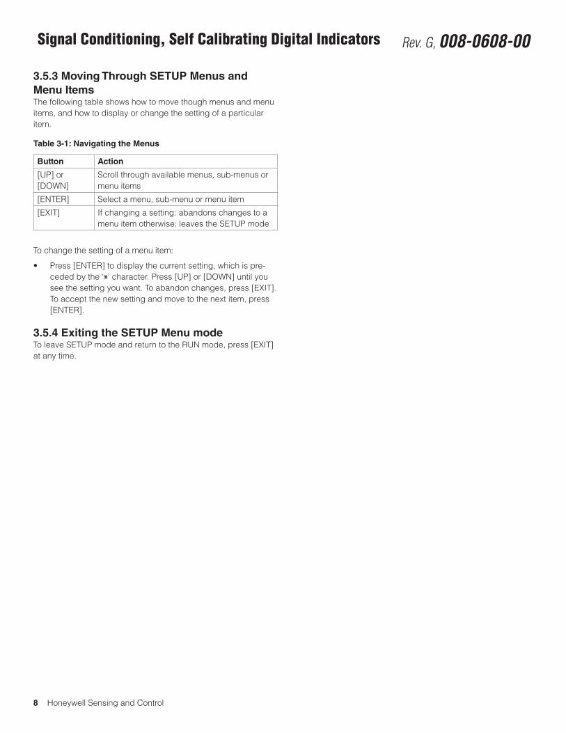
3.5.3 Moving Through SETUP Menus and Menu ItemsThe following table shows how to move though menus and menu items, and how to display or change the setting of a particular item.
Table 3-1: Navigating the Menus
Button Action
[UP] or [DOWN]
Scroll through available menus, sub-menus or menu items
[ENTER] Select a menu, sub-menu or menu item
[EXIT] If changing a setting: abandons changes to a menu item otherwise: leaves the SETUP mode
To change the setting of a menu item:
• Press[ENTER]todisplaythecurrentsetting,whichispre-ceded by the ‘*’ character. Press [UP] or [DOWN] until you see the setting you want. To abandon changes, press [EXIT]. To accept the new setting and move to the next item, press [ENTER].
3.5.4 Exiting the SETUP Menu modeTo leave SETUP mode and return to the RUN mode, press [EXIT] at any time.
Honeywell Sensing and Control 9
SC 2000, SC2001, SC3004 Rev. G, 008-0608-00
Chapter 4 Chassis Models
4.1 IntroductionThe SC Series of Signal Conditioners/Indicators are available in several different chassis models. In general, each chassis model operates in an identical fashion and can be ordered with any type of Input channels, Output channels, or Virtual channels.
Input channels and Output channels are printed circuit boards that occupy a physical slot inside the instrument’s chassis. 12-
pin connectors are located on the rear panel to connect to each Input or Output Channel. Each channel in the instrument is identi-fied by a number (channel 01, channel 02, etc.).
A Virtual channel exists in software only; it does not occupy a physical slot inside the instrument’s chassis. There is no rear-panel connector for a Virtual channel. However, a Virtual channel does require a channel number.
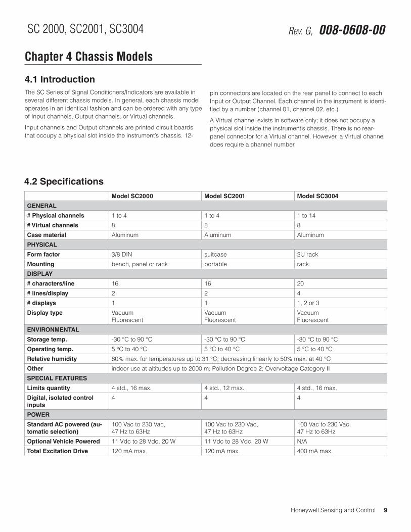
4.2 SpecificationsModel SC2000 Model SC2001 Model SC3004
GENERAL
# Physical channels 1 to 4 1 to 4 1 to 14
# Virtual channels 8 8 8
Case material Aluminum Aluminum Aluminum
PHYSICAL
Form factor 3/8 DIN suitcase 2U rack
Mounting bench, panel or rack portable rack
DISPLAY
# characters/line 16 16 20
# lines/display 2 2 4
# displays 1 1 1, 2 or 3
Display type VacuumFluorescent
VacuumFluorescent
VacuumFluorescent
ENVIRONMENTAL
Storage temp. -30 °C to 90 °C -30 °C to 90 °C -30 °C to 90 °C
Operating temp. 5 °C to 40 °C 5 °C to 40 °C 5 °C to 40 °C
Relative humidity 80% max. for temperatures up to 31 °C; decreasing linearly to 50% max. at 40 °C
Other indoor use at altitudes up to 2000 m; Pollution Degree 2; Overvoltage Category II
SPECIAL FEATURES
Limits quantity 4 std., 16 max. 4 std., 12 max. 4 std., 16 max.
Digital, isolated control inputs
4 4 4
POWER
Standard AC powered (au-tomatic selection)
100 Vac to 230 Vac, 47 Hz to 63Hz
100 Vac to 230 Vac, 47 Hz to 63Hz
100 Vac to 230 Vac, 47 Hz to 63Hz
Optional Vehicle Powered 11 Vdc to 28 Vdc, 20 W 11 Vdc to 28 Vdc, 20 W N/A
Total Excitation Drive 120 mA max. 120 mA max. 400 mA max.
10 Honeywell Sensing and Control
Signal Conditioning, Self Calibrating Digital Indicators Rev. G, 008-0608-00
4.3 Model SC2000
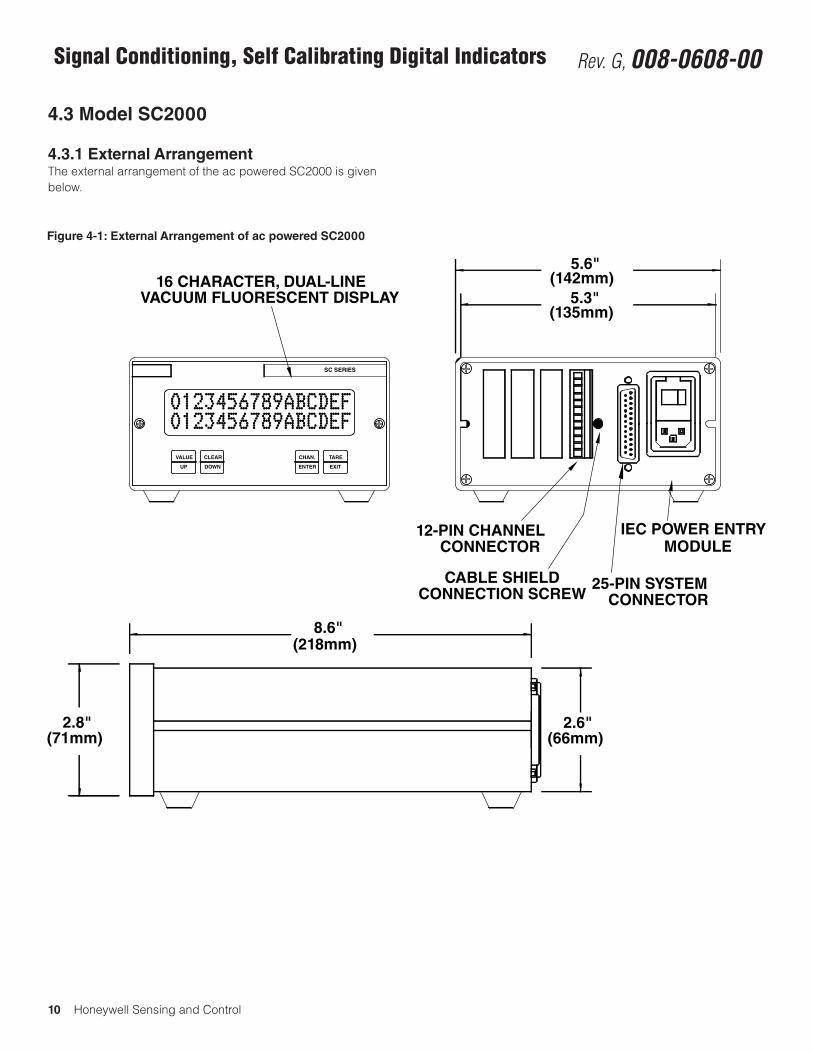
4.3.1 External ArrangementThe external arrangement of the ac powered SC2000 is given below.
Figure 4-1: External Arrangement of ac powered SC2000
8.6"
2.8" 2.6"
5.6"
5.3"
12-PIN CHANNEL
25-PIN SYSTEM
IEC POWER ENTRY
VACUUM FLUORESCENT DISPLAY16 CHARACTER, DUAL-LINE
(66mm)(71mm)
(218mm)
(135mm)
(142mm)
CONNECTOR
CONNECTOR
MODULE
CABLE SHIELDCONNECTION SCREW
SC SERIES
0123456789ABCDEF0123456789ABCDEF
VALUE
UP
CLEAR
DOWN
TARE
EXITENTER
CHAN.
Honeywell Sensing and Control 11
SC 2000, SC2001, SC3004 Rev. G, 008-0608-00
4.3.2 Rear PanelThe pinout for the 25-pin System connector is provided later in this chapter. The pinouts for the individual channels are located in the chapter for that channel.
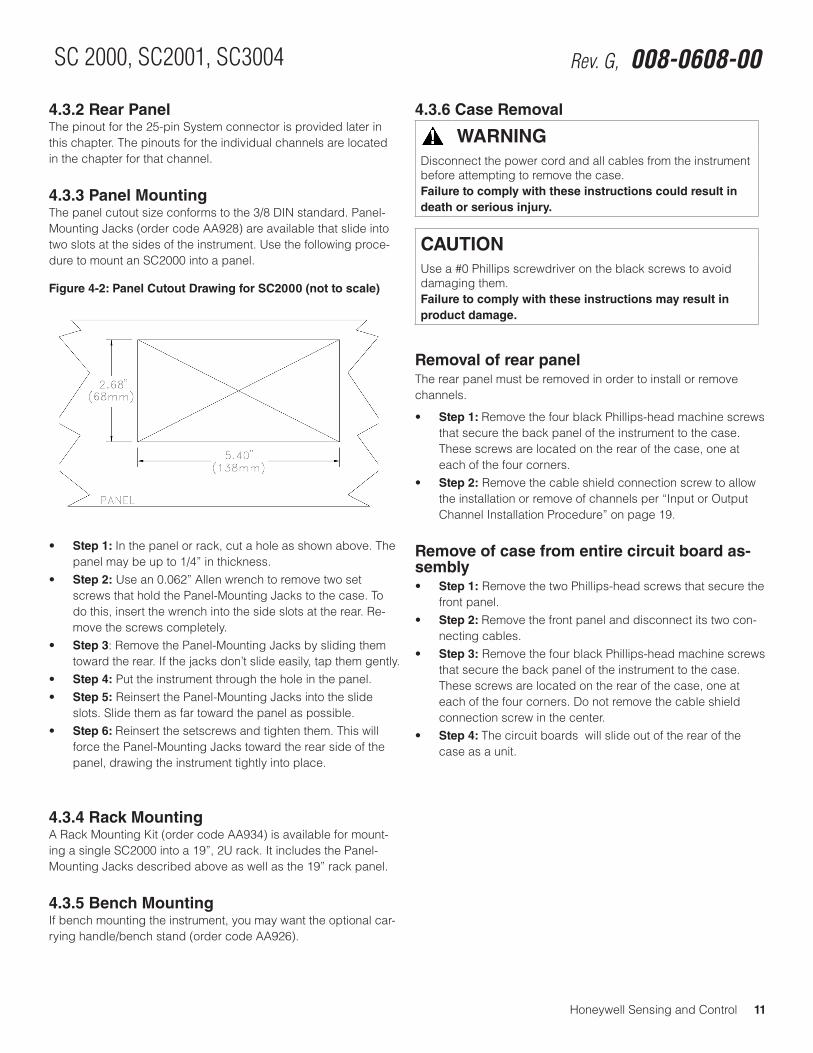
4.3.3 Panel MountingThe panel cutout size conforms to the 3/8 DIN standard. Panel-Mounting Jacks (order code AA928) are available that slide into two slots at the sides of the instrument. Use the following proce-dure to mount an SC2000 into a panel.
Figure 4-2: Panel Cutout Drawing for SC2000 (not to scale)
• Step 1: In the panel or rack, cut a hole as shown above. The panel may be up to 1/4” in thickness.
• Step 2: Use an 0.062” Allen wrench to remove two set screws that hold the Panel-Mounting Jacks to the case. To do this, insert the wrench into the side slots at the rear. Re-move the screws completely.
• Step 3: Remove the Panel-Mounting Jacks by sliding them toward the rear. If the jacks don’t slide easily, tap them gently.
• Step 4: Put the instrument through the hole in the panel.• Step 5: Reinsert the Panel-Mounting Jacks into the slide
slots. Slide them as far toward the panel as possible.• Step 6: Reinsert the setscrews and tighten them. This will
force the Panel-Mounting Jacks toward the rear side of the panel, drawing the instrument tightly into place.
4.3.4 Rack MountingA Rack Mounting Kit (order code AA934) is available for mount-ing a single SC2000 into a 19”, 2U rack. It includes the Panel-Mounting Jacks described above as well as the 19” rack panel.
4.3.5 Bench MountingIf bench mounting the instrument, you may want the optional car-rying handle/bench stand (order code AA926).
4.3.6 Case Removal
WARNINGDisconnect the power cord and all cables from the instrument before attempting to remove the case.Failure to comply with these instructions could result in death or serious injury.
CAUTIONUse a #0 Phillips screwdriver on the black screws to avoid damaging them.Failure to comply with these instructions may result in product damage.
Removal of rear panelThe rear panel must be removed in order to install or remove channels.
• Step 1: Remove the four black Phillips-head machine screws that secure the back panel of the instrument to the case. These screws are located on the rear of the case, one at each of the four corners.
• Step 2: Remove the cable shield connection screw to allow the installation or remove of channels per “Input or Output Channel Installation Procedure” on page 19.
Remove of case from entire circuit board as-sembly• Step 1: Remove the two Phillips-head screws that secure the
front panel.• Step 2: Remove the front panel and disconnect its two con-
necting cables.• Step 3: Remove the four black Phillips-head machine screws
that secure the back panel of the instrument to the case. These screws are located on the rear of the case, one at each of the four corners. Do not remove the cable shield connection screw in the center.
• Step 4: The circuit boards will slide out of the rear of the case as a unit.
12 Honeywell Sensing and Control
Signal Conditioning, Self Calibrating Digital Indicators Rev. G, 008-0608-00
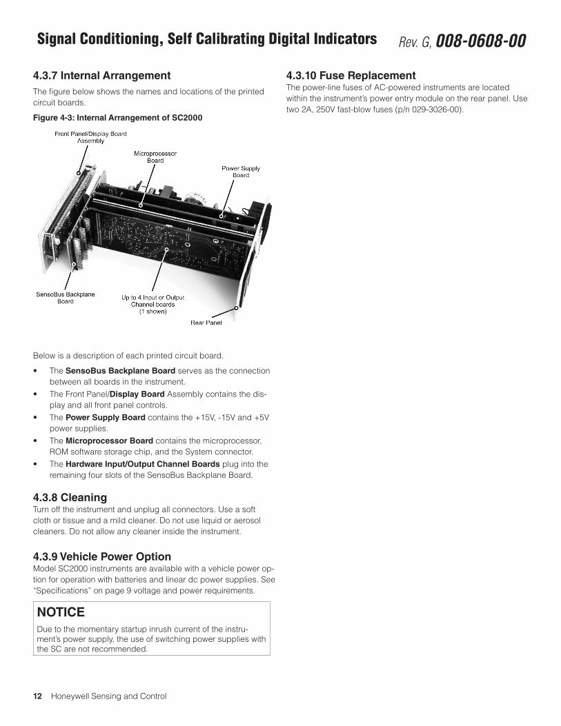
4.3.7 Internal Arrangement The figure below shows the names and locations of the printed circuit boards.
Figure 4-3: Internal Arrangement of SC2000
Below is a description of each printed circuit board.
• TheSensoBus Backplane Board serves as the connection between all boards in the instrument.
• TheFrontPanel/Display Board Assembly contains the dis-play and all front panel controls.
• ThePower Supply Board contains the +15V, -15V and +5V power supplies.
• TheMicroprocessor Board contains the microprocessor, ROM software storage chip, and the System connector.
• TheHardware Input/Output Channel Boards plug into the remaining four slots of the SensoBus Backplane Board.
4.3.8 CleaningTurn off the instrument and unplug all connectors. Use a soft cloth or tissue and a mild cleaner. Do not use liquid or aerosol cleaners. Do not allow any cleaner inside the instrument.
4.3.9 Vehicle Power OptionModel SC2000 instruments are available with a vehicle power op-tion for operation with batteries and linear dc power supplies. See “Specifications” on page 9 voltage and power requirements.
NOTICEDue to the momentary startup inrush current of the instru-ment’s power supply, the use of switching power supplies with the SC are not recommended.
4.3.10 Fuse ReplacementThe power-line fuses of AC-powered instruments are located within the instrument’s power entry module on the rear panel. Use two 2A, 250V fast-blow fuses (p/n 029-3026-00).
Honeywell Sensing and Control 13
SC 2000, SC2001, SC3004 Rev. G, 008-0608-00
4.4 Model SC2001
4.4.1 DifferencesModel SC2001 instruments are SC2000 instruments housed in a portable case.
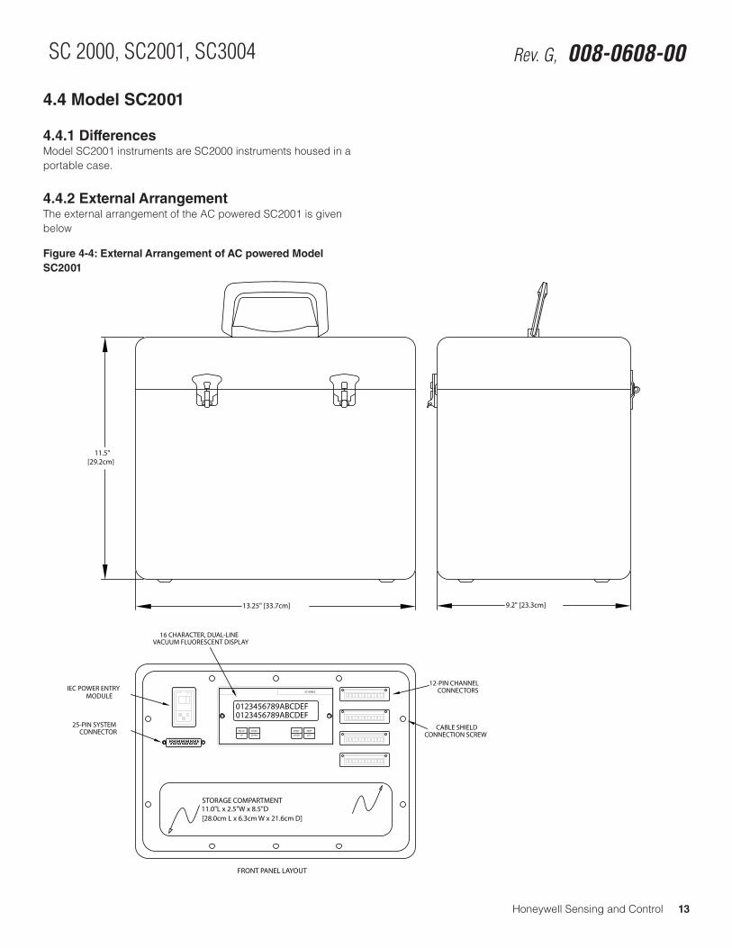
4.4.2 External ArrangementThe external arrangement of the AC powered SC2001 is given below
Figure 4-4: External Arrangement of AC powered Model SC2001
11.5" [29.2cm]
13.25" [33.7cm] 9.2" [23.3cm]
UP DOWN ENTER EXIT
0123456789ABCDEF0123456789ABCDEF
VALUE
SC SERIES
CLEAR CHAN. TARE
STORAGE COMPARTMENT11.0"L x 2.5"W x 8.5"D[28.0cm L x 6.3cm W x 21.6cm D]
12-PIN CHANNELCONNECTORS
MODULEIEC POWER ENTRY
16 CHARACTER, DUAL-LINEVACUUM FLUORESCENT DISPLAY
25-PIN SYSTEMCONNECTOR
CABLE SHIELDCONNECTION SCREW
FRONT PANEL LAYOUT
14 Honeywell Sensing and Control
Signal Conditioning, Self Calibrating Digital Indicators Rev. G, 008-0608-00
4.4.3 Front PanelThe pinout for the 25-pin System connector is provided later in this chapter. The pinouts for the individual channels are located in the chapter for that channel.
4.4.4 Case Removal
WARNINGDisconnect the power cord and all cables from the instrument before attempting to remove the case.Failure to comply with these instructions could result in death or serious injury.
• Step 1: Remove the 10 Phillips-head machine screws that secure the front panel to the case.
• Step 2: Pull the front panel assembly out of the case.• Step 3: Proceed with Model SC2000 “Case Removal” on
page 11.
4.4.5 Internal ArrangementSee the Model SC2000 “Internal Arrangement” on page 12.
4.4.6 CleaningTurn off the instrument and unplug all connectors. Use a soft cloth or tissue and a mild cleaner. Do not use liquid or aerosol cleaners. Do not allow any cleaner inside the instrument.
4.4.7 Vehicle Power OptionThe Model SC2001 is available with a vehicle power option for operation with batteries and linear dc power supplies. See “Spec-ifications” on page 26 voltage and power requirements..
NOTICEDue to the momentary startup inrush current of the instru-ment’s power supply, the use of switching power supplies with the SC are not recommended.
4.4.8 Fuse ReplacementThe power-line fuses of AC-powered instruments are located within the instrument’s power entry module on the rear panel. Use two 2 A, 250 V fast-blow fuses (p/n 029-3026-00).
Honeywell Sensing and Control 15
SC 2000, SC2001, SC3004 Rev. G, 008-0608-00
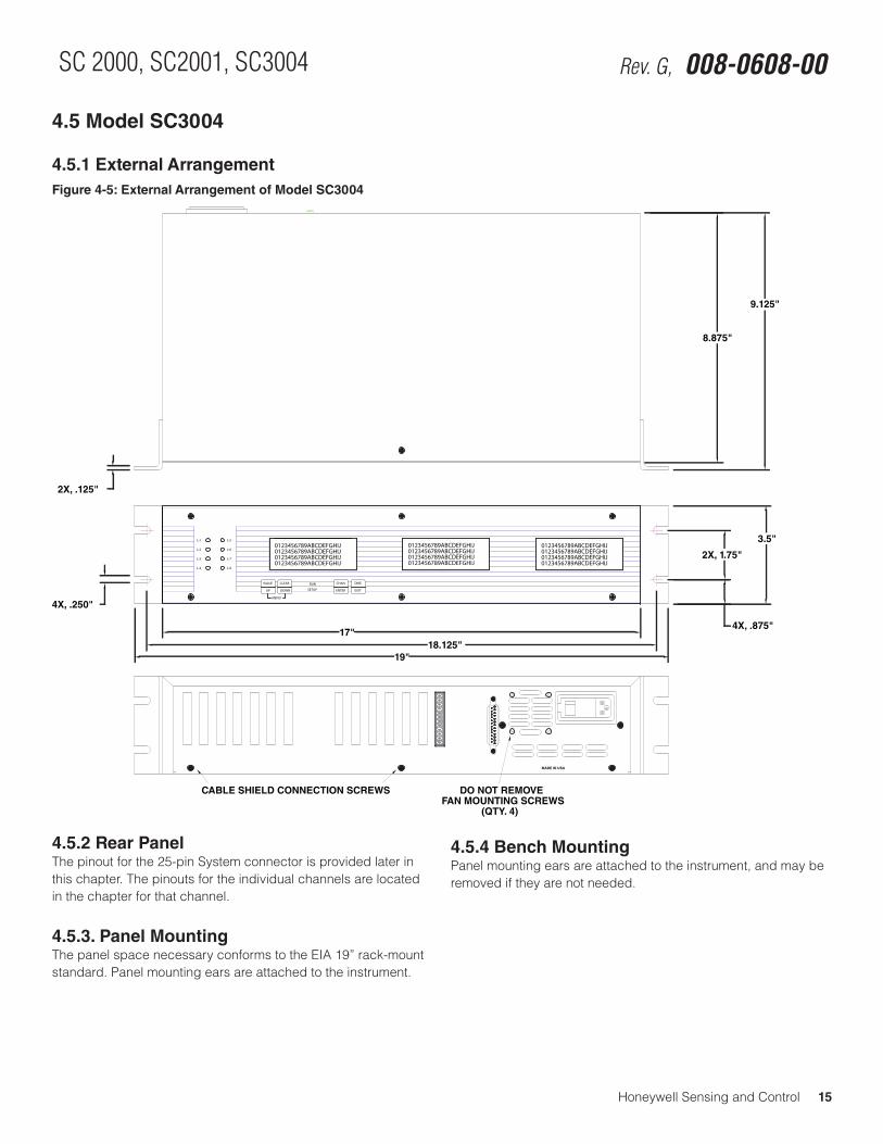
4.5 Model SC3004
4.5.1 External ArrangementFigure 4-5: External Arrangement of Model SC3004
L-4 L-8
ENTER
L-3
L-2
L-7
L-6
L-1 L-5
EXIT
CHAN. TAREVALUE RUN
SETUPUP
CLEAR
DOWN
MENU
0123456789ABCDEFGHIJ0123456789ABCDEFGHIJ
0123456789ABCDEFGHIJ0123456789ABCDEFGHIJ
0123456789ABCDEFGHIJ0123456789ABCDEFGHIJ0123456789ABCDEFGHIJ0123456789ABCDEFGHIJ
0123456789ABCDEFGHIJ
0123456789ABCDEFGHIJ0123456789ABCDEFGHIJ0123456789ABCDEFGHIJ
4X, .250"
2X, .125"
CABLE SHIELD CONNECTION SCREWS
(QTY. 4)FAN MOUNTING SCREWS
DO NOT REMOVE
MADE IN USA
17"18.125"
19"
4X, .875"
2X, 1.75"
3.5"
9.125"
8.875"
4.5.2 Rear PanelThe pinout for the 25-pin System connector is provided later in this chapter. The pinouts for the individual channels are located in the chapter for that channel.
4.5.3. Panel MountingThe panel space necessary conforms to the EIA 19” rack-mount standard. Panel mounting ears are attached to the instrument.
4.5.4 Bench MountingPanel mounting ears are attached to the instrument, and may be removed if they are not needed.
16 Honeywell Sensing and Control
Signal Conditioning, Self Calibrating Digital Indicators Rev. G, 008-0608-00
4.5.5 Case Removal
WARNINGDisconnect the power cord and all cables from the instrument before attempting to remove the case.Failure to comply with these instructions could result in death or serious injury.
CAUTIONUse a #0 Phillips screwdriver on the black screws to avoid damaging them.Failure to comply with these instructions may result in product damage.
• Step 1: Remove the four, silver rack-mounting ears from the left and right sides.
• Step 2: Remove one Phillips screw from the top of the case.• Step 3: Remove two Phillips screws from the bottom of the
black case cover.• Step 4: Remove the black case cover from the instrument.• Step 5: Remove eight Phillips screws from the rear panel,
including the two cable shield connection screws. NOTE: Do not remove the four screws which secure the cooling fan to the rear panel.
• Step 6: Remove the rear panel.
4.5.6 Rear PanelThe pinout for the 25-pin System connector is provided later in this chapter.
4.5.7 Internal ArrangementUser installable printed circuit boards will slide out of the rear of the case once the case and rear panel have been removed as described above.
4.5.8 CleaningTurn off the instrument and unplug all connectors. Use a soft cloth or tissue and a mild cleaner. Do not use liquid or aerosol cleaners. Do not allow any cleaner inside the instrument.
4.5.9 Fuse ReplacementThe power-line fuses are located within the instrument’s power entry module on the rear panel. Use two 2 A, 250 V fast-blow fuses (p/n 029-3026-00).
Honeywell Sensing and Control 17
SC 2000, SC2001, SC3004 Rev. G, 008-0608-00
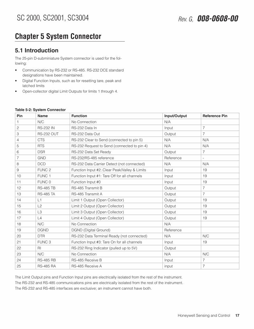
Chapter 5 System Connector
5.1 IntroductionThe 25-pin D-subminiature System connector is used for the fol-lowing:
• CommunicationbyRS-232orRS-485.RS-232DCEstandarddesignations have been maintained.
• DigitalFunctionInputs,suchasforresettingtare,peakandlatched limits
• Open-collectordigitalLimitOutputsforlimits1through4.
Table 5-2: System Connector
Pin Name Function Input/Output Reference Pin
1 N/C No Connection N/A
2 RS-232 IN RS-232 Data In Input 7
3 RS-232 OUT RS-232 Data Out Output 7
4 CTS RS-232 Clear to Send (connected to pin 5) N/A N/A
5 RTS RS-232 Request to Send (connected to pin 4) N/A N/A
6 DSR RS-232 Data Set Ready Output 7
7 GND RS-232/RS-485 reference Reference -
8 DCD RS-232 Data Carrier Detect (not connected) N/A N/A
9 FUNC 2 Function Input #2:.Clear Peak/Valley & Limits Input 19
10 FUNC 1 Function Input #1: Tare Off for all channels Input 19
11 FUNC 0 Function Input #0 Input 19
12 RS-485 TB RS-485 Transmit B Output 7
13 RS-485 TA RS-485 Transmit A Output 7
14 L1 Limit 1 Output (Open Collector) Output 19
15 L2 Limit 2 Output (Open Collector) Output 19
16 L3 Limit 3 Output (Open Collector) Output 19
17 L4 Limit 4 Output (Open Collector) Output 19
18 N/C No Connection N/A
19 DGND DGND (Digital Ground) Reference
20 DTR RS-232 Data Terminal Ready (not connected) N/A N/C
21 FUNC 3 Function Input #3: Tare On for all channels Input 19
22 RI RS-232 Ring Indicator (pulled up to 5V) Output
23 N/C No Connection N/A N/C
24 RS-485 RB RS-485 Receive B Input 7
25 RS-485 RA RS-485 Receive A input 7
The Limit Output pins and Function Input pins are electrically isolated from the rest of the instrument.The RS-232 and RS-485 communications pins are electrically isolated from the rest of the instrument.The RS-232 and RS-485 interfaces are exclusive; an instrument cannot have both.
18 Honeywell Sensing and Control
Signal Conditioning, Self Calibrating Digital Indicators Rev. G, 008-0608-00
5.3 Function Input Pins
5.3.1 OverviewTo use a Function Input pin (9, 10, 11 or 21), connect it to the DGND (pin 19) momentarily. This can be accomplished by a push button switch, relay contact closure, or PLC output.
Usually, the Function Input pins perform the default actions de-scribed in the “System Connector Pinout” on page 17. However, a SensoCode program running on a Mathematics Virtual Channel may replace these default actions. Consult the Customer Infor-mation Sheet included with your instrument for details.
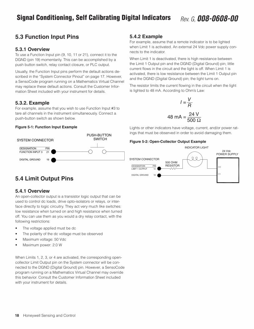
5.3.2. ExampleFor example, assume that you wish to use Function Input #3 to tare all channels in the instrument simultaneously. Connect a push-button switch as shown below.
Figure 5-1: Function Input Example
PUSH-BUTTONSWITCH
DIGITAL GROUND 19
DESIGNATION
FUNCTION INPUT 3
PIN
21
SYSTEM CONNECTOR
5.4 Limit Output Pins
5.4.1 OverviewAn open-collector output is a transistor logic output that can be used to control dc loads, drive opto-isolators or relays, or inter-face directly to logic circuitry. They act very much like switches: low resistance when turned on and high resistance when turned off. You can use them as you would a dry relay contact, with the following restrictions:
• Thevoltageappliedmustbedc• Thepolarityofthedcvoltagemustbeobserved• Maximumvoltage:50Vdc• Maximumpower:2.0W
When Limits 1, 2, 3, or 4 are activated, the corresponding open-collector Limit Output pin on the System connector will be con-nected to the DGND (Digital Ground) pin. However, a SensoCode program running on a Mathematics Virtual Channel may override this behavior. Consult the Customer Information Sheet included with your instrument for details.
5.4.2 ExampleFor example, assume that a remote indicator is to be lighted when Limit 1 is activated. An external 24 Vdc power supply con-nects to the indicator.
When Limit 1 is deactivated, there is high resistance between the Limit 1 Output pin and the DGND (Digital Ground) pin; little current flows in the circuit and the light is off. When Limit 1 is activated, there is low resistance between the Limit 1 Output pin and the DGND (Digital Ground) pin; the light turns on.
The resistor limits the current flowing in the circuit when the light is lighted to 48 mA. According to Ohm’s Law:
I = VR
48 mA = 24 V500 Ω
Lights or other indicators have voltage, current, and/or power rat-ings that must be observed in order to avoid damaging them.
Figure 5-2: Open-Collector Output Example
(+)
24 VdcPOWER SUPPLY
(-)
INDICATOR LIGHT
500 OHMRESISTOR
DIGITAL GROUND 19
DESIGNATION
LIMIT 1 OUTPUT
PIN
14
SYSTEM CONNECTOR
Honeywell Sensing and Control 19
SC 2000, SC2001, SC3004 Rev. G, 008-0608-00
Chapter 6 System Menu
6.1 OverviewThe System menu allows you to examine and change settings that affect the chassis of the SC instrument. You can view the internal software revision and the instrument’s configuration (i.e. what types of cards are installed in each channel).
Detailed instructions on operating the SC instrument in the SET-UP Menu mode can be found in “SETUP Menu mode” on page 7. A diagram of all menus is located in the “Setup Menu Reference” on page 77.
6.2 Menu Items
6.2.1 SOFTWARE REVISION Menu ItemThis displays the software part number and revision that is resi-dent in the Microprocessor Board of the SC instrument.
6.2.2 CONFIGURATION Sub-MenuWhen selected, a sub-menu is displayed which lists all avail-able channels in an SC Series instrument. By pressing [ENTER] when a channel number is displayed, the card type installed in that channel is shown. If a card is not installed in that channel, the message “NOT INSTALLED” is shown. Press [ENTER] again to return to the sub-menu listing of all channels.
6.2.3 DIAGNOSTICS Sub-MenuThis sub-menu allows exercising and monitoring of the System connector’s output and input pins.
OUTPUT n, PIN nn Menu ItemsThese menus items are used to select an output pin to turn “on” (connected to pin 19) or “off” (disconnected from pin 19). The output pins are updated immediately.INPUT TEST Menu ItemWhen this item is selected, the status of all four digital inputs are continuously scanned and displayed. A “0” means that an input is not connected to pin 19 (not asserted), and a “1” means that it is connected (asserted). Press any button to exit this operation.SCAN TIME Menu ItemWhen selected, this menu item displays the time, in seconds, that it last took for the chassis to service all of the channels. In the RUN mode, the chassis reads each channel’s track, peak and valley value sequentially. After each channel has been serviced, the limits are processed.The value displayed is obtained from the last execution of the RUN mode prior to entering the SETUP menu mode. If you enter the SETUP mode immediately after power up, the display will read “NOT AVAILABLE”.
6.2.4 INSTALL CHANNEL Menu ItemThis menu item will add an Input, Output or Virtual channel as the next highest channel number in the system.
NOTICEInstalling a channel will cause it to use the “default” or “empty” configuration information for that channel. All other channels are unaffected.Any calibration data, SensoCode mathematics programs, display setup, or other information for that channel will be erased to default values.
Input or Output Channel Installation ProcedureBefore installing an Input or Output card, make certain that you know the “card type” (a two-digit hexadecimal number) of the card you wish to install.
CAUTIONUse Electrostatic Discharge (ESD) precautions when unpack-ing and handling circuit boards..Failure to comply with these instructions may result in product damage.
Use the following procedure to install an Input or Output card:
1. When the instrument is in the RUN mode, use the [ENTER] button to change which channel the display is monitoring. Note the highest channel number that is presently installed. The new circuit card for the new channel will be installed as the next channel number.
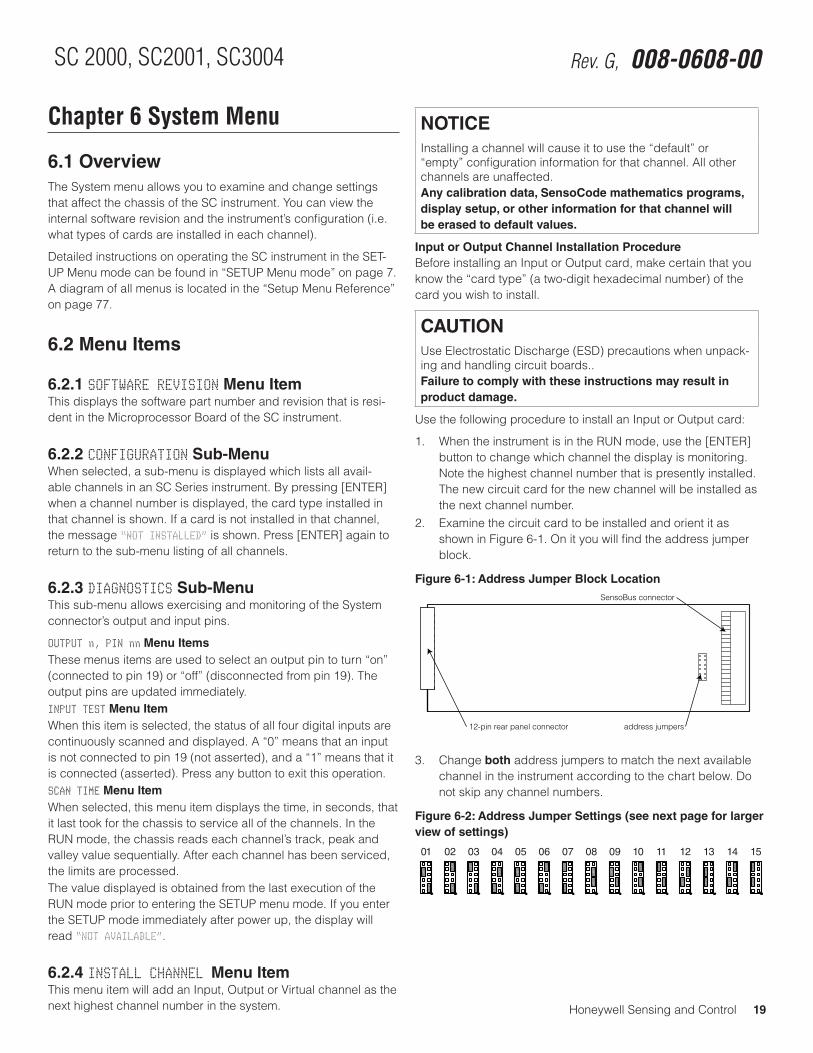
2. Examine the circuit card to be installed and orient it as shown in Figure 6-1. On it you will find the address jumper block.
Figure 6-1: Address Jumper Block Location
12-pin rear panel connector address jumpers
SensoBus connector
3. Change both address jumpers to match the next available channel in the instrument according to the chart below. Do not skip any channel numbers.
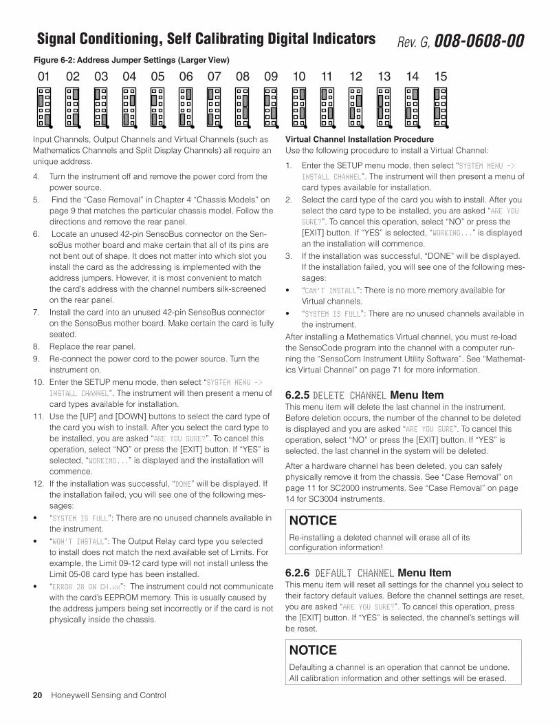
Figure 6-2: Address Jumper Settings (see next page for larger view of settings)
0401 02 03 0705 06 0908 10 1211 13 14 15
20 Honeywell Sensing and Control
Signal Conditioning, Self Calibrating Digital Indicators Rev. G, 008-0608-00
Input Channels, Output Channels and Virtual Channels (such as Mathematics Channels and Split Display Channels) all require an unique address.
4. Turn the instrument off and remove the power cord from the power source.
5. Find the “Case Removal” in Chapter 4 “Chassis Models” on page 9 that matches the particular chassis model. Follow the directions and remove the rear panel.
6. Locate an unused 42-pin SensoBus connector on the Sen-soBus mother board and make certain that all of its pins are not bent out of shape. It does not matter into which slot you install the card as the addressing is implemented with the address jumpers. However, it is most convenient to match the card’s address with the channel numbers silk-screened on the rear panel.
7. Install the card into an unused 42-pin SensoBus connector on the SensoBus mother board. Make certain the card is fully seated.
8. Replace the rear panel.9. Re-connect the power cord to the power source. Turn the
instrument on.10. Enter the SETUP menu mode, then select “SYSTEM MENU ->
INSTALL CHANNEL”. The instrument will then present a menu of card types available for installation.
11. Use the [UP] and [DOWN] buttons to select the card type of the card you wish to install. After you select the card type to be installed, you are asked “ARE YOU SURE?”. To cancel this operation, select “NO” or press the [EXIT] button. If “YES” is selected, “WORKING...” is displayed and the installation will commence.
12. If the installation was successful, “DONE” will be displayed. If the installation failed, you will see one of the following mes-sages:
• “SYSTEM IS FULL”: There are no unused channels available in the instrument.
• “WON’T INSTALL”: The Output Relay card type you selected to install does not match the next available set of Limits. For example, the Limit 09-12 card type will not install unless the Limit 05-08 card type has been installed.
• “ERROR 28 ON CH.xx”: The instrument could not communicate with the card’s EEPROM memory. This is usually caused by the address jumpers being set incorrectly or if the card is not physically inside the chassis.
Virtual Channel Installation ProcedureUse the following procedure to install a Virtual Channel:
1. Enter the SETUP menu mode, then select “SYSTEM MENU -> INSTALL CHANNEL”. The instrument will then present a menu of card types available for installation.
2. Select the card type of the card you wish to install. After you select the card type to be installed, you are asked “ARE YOU SURE?”. To cancel this operation, select “NO” or press the [EXIT] button. If “YES” is selected, “WORKING...” is displayed an the installation will commence.
3. If the installation was successful, “DONE” will be displayed. If the installation failed, you will see one of the following mes-sages:
• “CAN’T INSTALL”: There is no more memory available for Virtual channels.
• “SYSTEM IS FULL”: There are no unused channels available in the instrument.
After installing a Mathematics Virtual channel, you must re-load the SensoCode program into the channel with a computer run-ning the “SensoCom Instrument Utility Software”. See “Mathemat-ics Virtual Channel” on page 71 for more information.
6.2.5 DELETE CHANNEL Menu ItemThis menu item will delete the last channel in the instrument. Before deletion occurs, the number of the channel to be deleted is displayed and you are asked “ARE YOU SURE”. To cancel this operation, select “NO” or press the [EXIT] button. If “YES” is selected, the last channel in the system will be deleted.
After a hardware channel has been deleted, you can safely physically remove it from the chassis. See “Case Removal” on page 11 for SC2000 instruments. See “Case Removal” on page 14 for SC3004 instruments.
NOTICERe-installing a deleted channel will erase all of its configuration information!
6.2.6 DEFAULT CHANNEL Menu ItemThis menu item will reset all settings for the channel you select to their factory default values. Before the channel settings are reset, you are asked “ARE YOU SURE?”. To cancel this operation, press the [EXIT] button. If “YES” is selected, the channel’s settings will be reset.
NOTICEDefaulting a channel is an operation that cannot be undone. All calibration information and other settings will be erased.
Figure 6-2: Address Jumper Settings (Larger View)
0401 02 03 0705 06 0908 10 1211 13 14 15
Honeywell Sensing and Control 21
SC 2000, SC2001, SC3004 Rev. G, 008-0608-00
Chapter 7 Serial Communications
7.1 OverviewThe SC Series instruments are designed to communicate with a remote computer system or terminal for the purpose of transfer-ring data values from the instrument to the remote system. The re-mote computer or terminal also can control many of the functions performed by the instrument.
This chapter is a brief introduction to serial communications with SC Series instruments. A separate instruction manual is available to assist with the hookup and wiring for data communications as well as provide detailed information of all the available com-mands. Ask for manual 008-0610-00, “SC Series Communica-tions Guide” or download it from http://measurementsensors.honeywell.com.
7.2 WiringThe System connector on the instrument’s rear panel is used, among other things, for serial communications. See “System Con-nector” on page 17 for wiring information.
All of the serial communications pins on the 25-pin System con-nector have 500 V of electrical isolation from all other pins and connectors on the instrument. Additionally, all serial communica-tions pins are protected against electrostatic discharge (ESD).
7.3 Communications Protocol
7.3.1 RS-232 vs. RS-485SC Series instruments are available with either of two communi-cations protocols, RS-232 or RS-485. Only one of these can be installed at a time at the factory.
• RS-232providesforonlyonereceiverandtransmitterperloop, and a loop length of no more than 50 feet.
• RS-485allowsupto32devicesperloop,andalooplengthof no more than 4000 feet. All devices receive messages in parallel on the line, the so-called “multi-drop” system. To avoid garbled transmissions, only one device should respond to a particular message. Therefore, every device on the loop must have a unique address.
If you have an instrument with more than one channel, transmis-sion must be addressed to the appropriate channel within the instrument.
7.3.2 ParametersAll SC instruments use no parity, 8 data bits, and 1 stop bits (“N,8,1”) for serial communications. Baud rates available are 300, 600, 1200, 2400, 4800, 9600, 19200 and 38400. As shipped from the factory, all instruments are set at 9600 baud. The baud rate can be selected though the front panel.
7.4 Serial Com Menu
7.4.1 OverviewThe Serial Com menu allows you to examine and change the settings for serial communications as well as test the communica-tions link.
Detailed instructions on operating the SC instrument in the SET-UP Menu mode can be found in “SETUP Menu mode” on page 7. A diagram of all menus is located in “Setup Menu Reference” on page 77.
7.4.2 INTERFACE Menu ItemThis menu item indicates which serial communications interface is installed in the instrument: “RS-232” or “RS-485”.
7.4.3. ADDRESS Menu Item This allows you to examine and change the two-character ad-dress that the instrument will respond to. The default address of “00” (ASCII codes decimal 30, decimal 30).
7.4.4. BAUD RATE Menu ItemThis allows you to examine and change the baud rate that the instrument uses for serial communications. The default baud rate is 9600.
7.4.5 AUTO LINE-FEED Menu ItemThis allows you to examine the setting (on/off) of the auto line-feed function. When set to “on”, a line-feed character (ASCII code decimal 10) is transmitted just before the carriage return (ASCII code decimal 13) that signifies the end of the instrument’s response.
If the instrument is connected to a dumb terminal or printer, inserting a line feed before the carriage return will make each message sent by the instrument appear on a separate line and thus be easier to read.
The default setting is “on”.
22 Honeywell Sensing and Control
Signal Conditioning, Self Calibrating Digital Indicators Rev. G, 008-0608-00
7.4.6 TRANSMIT TEST Menu ItemWhen this menu item is selected, the instrument immediately transmits the message “ADDRESS nn TEST” where “nn” is the two-character address of the instrument. Then the message “MESSAGE SENT” is shown on the display. This helps detect wiring or other problems with serial communications from the instrument to the computer or PLC.
7.4.7 LEAVE MENU Menu ItemWhen the menu item is displayed, press [ENTER] to leave this menu. Press [EXIT] to return to the RUN mode.
Honeywell Sensing and Control 23
SC 2000, SC2001, SC3004 Rev. G, 008-0608-00
Chapter 8 Display Menu
8.1 OverviewThe Display menu allows you to examine and change settings that affect the operation of the display of the SC instrument. You can change which channel is displayed when the instrument is powered-up and what information is shown on the lower line of SC2000 and SC2001 instruments.
Detailed instructions on operating the SC instrument in the SETUP Menu mode can be found in “SETUP Menu mode” on page 7. A diagram of all menus is located in the “Setup Menu Reference” on page 77.
8.2 Menu Items for Models SC2000, SC2001These instruments have a dual-line display which consists of an upper line and a lower line.
8.2.1 UPPER CHANNEL Menu ItemSpecifies the channel that is displayed on the upper line when the instrument is powered-up.
To change whether the channel’s track, peak or valley data value is displayed on power-up, use the channel’s “OPERATION -> POWER-ON SOURCE” menu item.
8.2.2 LOWER CHANNEL Menu ItemSpecifies the channel that is displayed on the lower line when the “LOWER MODE” menu item is set to “CHANNEL”.
To change whether the channel’s track, peak or valley data value is displayed on power-up, use the channel’s “OPERATION -> POWER-ON SOURCE” menu item.
8.2.3 LOWER MODE Menu ItemDetermines what is displayed on the lower line. The choices are:
• “BLANK” means that nothing is displayed.• “LIMIT 01-04” means that the status of Limit 1, Limit 2, Limit
3, and Limit 4 are displayed as described in “Indicator Lights” on page 7
• “CHANNEL” means that the channel specified with the “LOWER CHANNEL” menu item is displayed.
8.2.4 DISPLAY DISABLE Menu ItemDetermines if the display is enabled or not. In some applications, the display is not used in order to reduce power consumption; the instrument is then completely controlled with the Serial Com-munications interface. The choices are:
• “OFF” means that the display operates normally.• “ON” means that the display is blanked after the instrument
is powered up. Pressing any button on the front panel will temporarily re-enable the display until the instrument is reset.
8.3 Menu Items for Model SC3004
8.3.1 POWER-ON CHANNEL Menu ItemSpecifies the channel that is selected when the instrument is powered up.
To change whether the channel’s track, peak or valley data value is displayed on power-up, use the channel’s “OPERATION -> POWER-ON SOURCE” menu item.
24 Honeywell Sensing and Control
Signal Conditioning, Self Calibrating Digital Indicators Rev. G, 008-0608-00
Chapter 9 Limits
9.1 Understanding Limits, Set Points and Return PointsLimits are signal levels at which some action (such as a light to come on or go out, or a switch to close) is desired to take place. The point at which this action takes place is the SET POINT. The RETURN POINT is the point at which the action that took place at the SET POINT returns to its original state.
If the SET POINT and RETURN POINT are identical and the signal level is changing slowly near these points, “chatter” may result and the limit rapidly energizes and de-energizes. To keep this from happening, we can specify the SET POINT at which the action would occur as well as the RETURN POINT where we want the action to cease. If the amount of “dead band” between these two values is more than the expected noise, the desired ac-tion will take place only once. The SET POINT and the RETURN POINT should always be separated to insure that small amounts of noise on the signal will not become a problem.
A good general rule for SET POINT and RETURN POINT values is that they should be separated by at least one percent of the full-scale value.
9.2 Limit Operation
9.2.1 Actions When ActivatedWhen Limits 1, 2, 3, or 4 are activated, the following actions oc-cur:
• Thefrontpanellightforthelimitwillilluminate.• Thecorrespondingopen-collectorLimitOutputpinonthe
System connector will be connected to the DGND (Digital Ground) pin.
• IfaRelayOutputchannelisinstalled,therelayforthelimitwill activate.
A Relay Output channel can be installed for Limits 5, 6, 7, and 8. When these limits are activated, the following actions occur:
• IfthedisplayismonitoringthechannelofthisRelayOutputchannel, the display will indicate the status of these limits.
• OnaModelSC3004,thefrontpanellightforthelimitwillilluminate.
• TherelayforthelimitonthisRelayOutputchannelwillacti-vate.
A Relay Output channel can be installed for Limits 9, 10, 11 and 12. When these limits are activated, the following actions occur:
• IftheRelayOutputchannelisdisplayed,thedisplaywillindicate the status of these limits.
• TherelayforthelimitonthisRelayOutputchannelwillacti-vate.
A Relay Output channel can be installed for Limits 13, 14, 15 and 16. When these limits are activated, the following actions occur:
• IftheRelayOutputchannelisdisplayed,thedisplaywillindicate the status of these limits.
• TherelayforthelimitonthisRelayOutputchannelwillacti-vate.
9.2.2 Scan TimeThe “scan time” or update rate of the limits depends on how many channels are installed in the instrument. To determine the scan time of the limits for your particular instrument, see “SCAN TIME Menu Item” on page 19.
9.3 Limit Menus
9.3.1 OverviewThere are four, eight, twelve or sixteen Limit menus depending on how many Relay Output channels are installed in the instrument. These menus determine the operation of the each of the limits.
If no Relay Output channels are installed, there are four Limit menus which control the operation of the open-collector Limit Outputs on the System connector.
Detailed instructions on operating the instrument in the SETUP Menu mode can be found in “SETUP Menu mode” on page 7. A diagram of all menus is located in “Setup Menu Reference” on page 77.
9.3.2 LIMIT.ENABLE Menu Item This enables or disables the operation of this limit. The two op-tions for this menu item are “ON” and “OFF”.
9.3.3 LIMIT.SETPOINT Menu ItemThis is the numeric value in engineering units for the signal level that activates the limit.
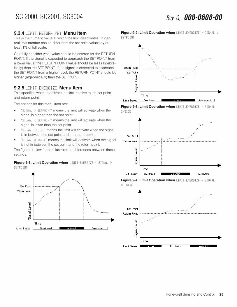
Honeywell Sensing and Control 25
SC 2000, SC2001, SC3004 Rev. G, 008-0608-00
9.3.4 LIMIT.RETURN PNT Menu ItemThis is the numeric value at which the limit deactivates. In gen-eral, this number should differ from the set point values by at least 1% of full scale.
Carefully consider what value should be entered for the RETURN POINT. If the signal is expected to approach the SET POINT from a lower value, the RETURN POINT value should be less (algebra-ically) than the SET POINT. If the signal is expected to approach the SET POINT from a higher level, the RETURN POINT should be higher (algebraically) than the SET POINT.
9.3.5 LIMIT.ENERGIZE Menu ItemThis specifies when to activate the limit relative to the set point and return point.
The options for this menu item are:
• “SIGNAL > SETPOINT” means the limit will activate when the signal is higher than the set point.
• “SIGNAL < SETPOINT” means the limit will activate when the signal is lower than the set point.
• “SIGNAL INSIDE” means the limit will activate when the signal is in between the set point and the return point.
• “SIGNAL OUTSIDE” means the limit will activate when the signal is not in between the set point and the return point.
The figures below further illustrate the differences between these settings.
Figure 9-1: Limit Operation when LIMIT.ENERGIZE = SIGNAL > SETPOINT
Figure 9-2: Limit Operation when LIMIT.ENERGIZE = SIGNAL < SETPOINT
Figure 9-3: Limit Operation when LIMIT.ENERGIZE = SIGNAL INSIDE
Figure 9-4: Limit Operation when LIMIT.ENERGIZE = SIGNAL OUTSIDE
26 Honeywell Sensing and Control
Signal Conditioning, Self Calibrating Digital Indicators Rev. G, 008-0608-00
9.3.6 LIMIT.LATCHING Menu ItemThis specifies whether to latch the activated limit so that only manually clearing the limit will deactivate it. A latched limit can be manually cleared by pressing the [CLEAR] button, sending the “F8” serial communications command, or by using the Function Input #2 (Clear Peak/Valley & Limits pin on the System Connector. See “Function Input Pins” on page 18.
The options for this menu item are:
• “ON” means that once a signal activates the limit, the limit will remain activated until it is reset.
• “OFF” means that the limit will deactivate immediately when the signal crosses the return point.
9.3.7 LIMIT.CHANNEL Menu ItemThis specifies the channel that is monitored by this limit.
9.3.8 LIMIT.SOURCE Menu ItemThis designates the data source of the channel monitored by this limit. Each channel has three data sources: the live tracking value (TRACK), its highest value (PEAK), and its lowest value (VALLEY).
The options for this menu item are:
• “TRACK” means the live tracking value of the channel. • “PEAK” means the highest value of the channel since the
peak/valley detector was last cleared.• “VALLEY” means the lowest value of the channel since the
peak/valley detector was last cleared.
9.3.9 LEAVE MENU Menu ItemWhen the menu item is displayed, press [ENTER] to leave this menu. Press [EXIT] to return to the RUN mode.
Chapter 10 Strain-Gage Input Channel
10.1 FeaturesThe Strain-Gage Input channel provides a dc excitation voltage to and accepts millivolt signals from strain-gage transducers. These millivolt signals are digitized, converted into engineering units, and placed into the track, peak and valley data values of the channel. Setup and calibration of the channel can be made manually through the SETUP mode or automatically if the trans-ducers are equipped with Signature Calibration. See “What is Signature Calibration?” on page 3.
The analog-to-digital converter input circuit is ratiometric to the excitation voltage, features adjustable digital, low-pass filtering, 12- to 18-bit resolution (depending on the filter setting) and has several different mV/V input ranges. These many input ranges al-low±50,000countresolution(attheslowestfiltersetting)acrossa wide variety of mV/V input ranges.
Three methods of calibrating the Strain-Gage Input channel to the transducer are available: known-load calibration, shunt calibra-tion and mV/V calibration. The benefits of each are discussed in “CALIBRATION TYPE Menu Item” on page 31.
Two rear panel control inputs can be field-configured for such functions as remote tare, disabling peak/valley detection and clearing the peak/valley values. A voltage or current digital-to-analog output is also provided.
Many diagnostic functions are performed automatically to insure correct wiring and operation of the transducer.
FP2000 TransducersThe Strain-Gage Input channel has its own internal shunt resis-tor for use in Shunt Calibration. It is not compatible with FP2000 mV/V output transducers that are equipped with “Buffered Shunt Calibration”. If you wish to use Shunt Calibration with an FP2000 transducer, use an FP2000 with Buffered Shunt cal and amplified output (e.g. 5 Vdc, 10 Vdc or 4 mA to 20 mA) connected to an SC’s High-Level Input channel.
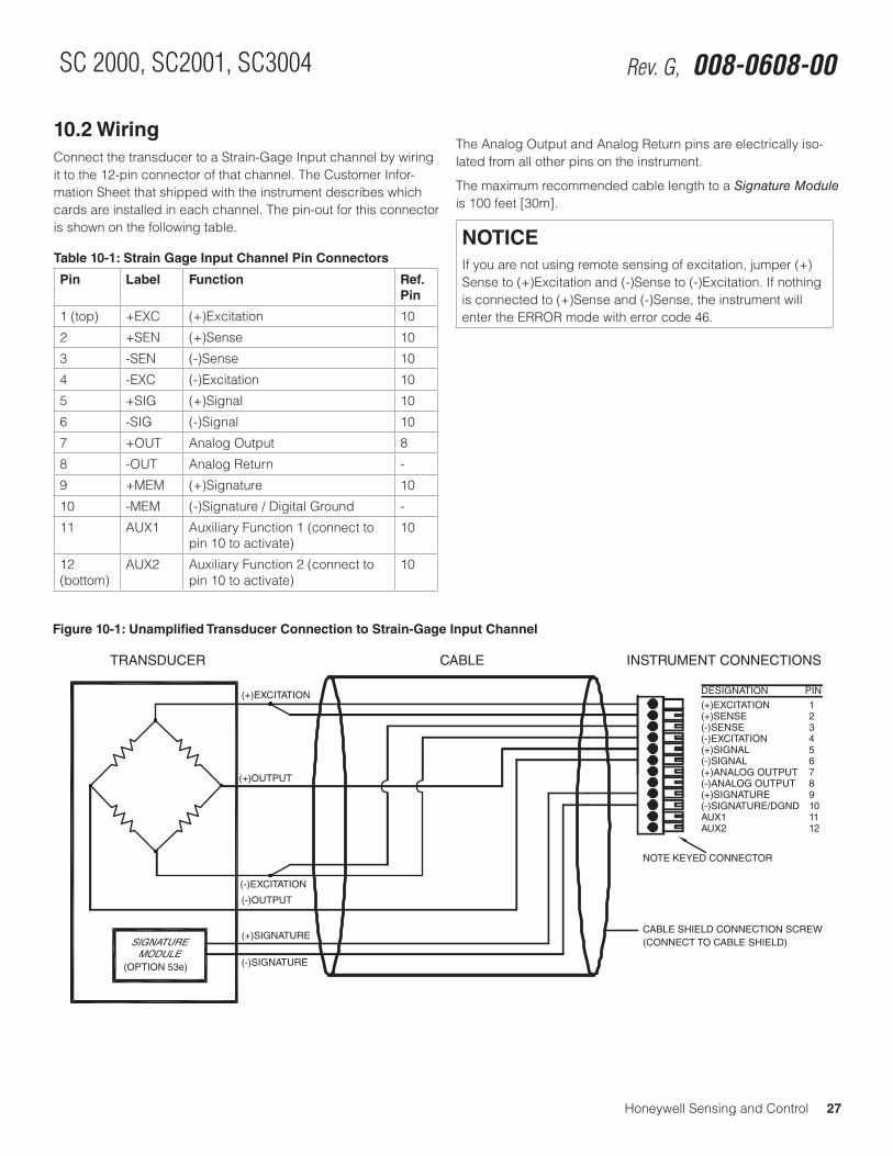
Honeywell Sensing and Control 27
SC 2000, SC2001, SC3004 Rev. G, 008-0608-00
10.2 WiringConnect the transducer to a Strain-Gage Input channel by wiring it to the 12-pin connector of that channel. The Customer Infor-mation Sheet that shipped with the instrument describes which cards are installed in each channel. The pin-out for this connector is shown on the following table.
Table 10-1: Strain Gage Input Channel Pin Connectors
Pin Label Function Ref. Pin
1 (top) +EXC (+)Excitation 10
2 +SEN (+)Sense 10
3 -SEN (-)Sense 10
4 -EXC (-)Excitation 10
5 +SIG (+)Signal 10
6 -SIG (-)Signal 10
7 +OUT Analog Output 8
8 -OUT Analog Return -
9 +MEM (+)Signature 10
10 -MEM (-)Signature / Digital Ground -
11 AUX1 Auxiliary Function 1 (connect to pin 10 to activate)
10
12 (bottom)
AUX2 Auxiliary Function 2 (connect to pin 10 to activate)
10
The Analog Output and Analog Return pins are electrically iso-lated from all other pins on the instrument.
The maximum recommended cable length to a Signature Module is 100 feet [30m].
NOTICEIf you are not using remote sensing of excitation, jumper (+)Sense to (+)Excitation and (-)Sense to (-)Excitation. If nothing is connected to (+)Sense and (-)Sense, the instrument will enter the ERROR mode with error code 46.
Figure 10-1: Unamplified Transducer Connection to Strain-Gage Input Channel
123456789101112
(+)EXCITATION(+)SENSE(-)SENSE(-)EXCITATION(+)SIGNAL(-)SIGNAL(+)ANALOG OUTPUT(-)ANALOG OUTPUT(+)SIGNATURE(-)SIGNATURE/DGNDAUX1AUX2
DESIGNATION PIN
CABLE SHIELD CONNECTION SCREW
(+)EXCITATION
(-)EXCITATION
(+)OUTPUT
(-)OUTPUT
TRANSDUCER CABLE INSTRUMENT CONNECTIONS
(CONNECT TO CABLE SHIELD)SIGNATUREMODULE
(+)SIGNATURE
(-)SIGNATURE
NOTE KEYED CONNECTOR
(OPTION 53e)
28 Honeywell Sensing and Control
Signal Conditioning, Self Calibrating Digital Indicators Rev. G, 008-0608-00
10.3 Calibration ProcedureIf you are not familiar with operating the instrument in the SETUP menu mode, see “SETUP Menu mode” on page 7. A listing of all menu items is given in “Setup Menu Reference” on page 77.
• Step1:Wirethetransducertothechannel’sconnector. See “Wiring” on page 27 for details.
• Step2:EntertheCALIBRATION TYPE. There are three methods that can be used to calibrate the
transducer to the Input Channel. Each has advantages and disadvantages as described in “CALIBRATION TYPE Menu Item” on page 31. It is important to know your application in order to select the appropriate calibration type.
• Step3:EntertheCALIBRATION DATA. - If your transducer has Signature Calibration, you don’t
need to enter these values as they are entered automatically. - If your transducer was ordered and shipped along with
the instrument, you don’t need to enter these values as they have been entered at the factory.
- Otherwise, consult the Certificate of Calibration for the transducer when entering information in the CALIBRATION DATA sub-menu.
• Step4:Performthecalibration. Otherwise, use the CALIBRATE menu item to start the calibra-
tion process. You will be prompted to apply loads to the transducer as required.
10.4 SpecificationsTRANSDUCER INPUT
Transducer type full-bridge, strain gage
Excitation voltage 5 Vdc or 10 Vdc, short circuit pro-tected with sensing
Transducer full-scale output
0.5 to 11.0 mV/V @ 5V excitation0.5 to 5.5 mV/V @ 10 V excitation
Amplifier gain selection automatic
Calibration type shunt, mV/V or 2-, 3- or 5-point known load
Differential Input Volt-age
±55mV(max.)
A/D Converter 24-bit Sigma-Delta
Low-pass filter digital, 24-tap FIR
Resolution and Fre-quency Response
see “FREQ. RESPONSE Menu Item” on page 29
INSTRUMENT-ONLY ACCURACY(Sense wires used; frequency response setting <16 Hz; Linearity, repeatability, and hysteresis)
mV/V calibration ±0.1%FS
Known-load calibration ±0.01%FS
AUXILLARY INPUTS
Quantity 2
Type momentary contact closure
Response time < 5 ms
Field-selectable func-tions
tare on, tare off, peak/valley clear, peak/valley hold, track hold
ANALOG OUTPUTS
Output voltage range 5,±5,10or±10Vdc (field selectable)
Output current range (optional current output channels)
4 mA to 20 mA
Source any channel’s track, peak, or valley value
Isolation 500 V
Resolution 13 bits
Frequency response same as input when driven by the same channel’s tracking data
Honeywell Sensing and Control 29
SC 2000, SC2001, SC3004 Rev. G, 008-0608-00
10.5 Channel MenuEach Strain-Gage Input channel is configured and calibrated via its channel menu. Detailed instructions on operating the instru-ment in the SETUP Menu mode can be found in “SETUP Menu mode” on page 7. A diagram of all menus is located in “Setup Menu Reference” on page 77.
10.5.1 OPERATION Sub-MenuThis menu controls the operation of this channel when the instru-ment is in the RUN mode.
AUTO-ZERO Menu ItemThis enables or disables the channel’s automatic zeroing func-tion. The auto-zero function can be beneficial by removing the effect of slight temperature shifts in the transducer’s output. The two options for this menu item are “ON” and “OFF”.
When enabled, the channel will reset its tracking value to zero when the tracking value has never been more positive than +10 or more negative than -10 display counts for any 10 second period.
For example, assume that the DISPLAY.DECPT menu item is set to 000.00 (two decimal points). If the tracking value never leaves the range of -000.10 to +000.10 for any 10 second period, then track-ing value will reset to 000.00 automatically.
NOTICETo compensate for the transducer’s initial warm-up shift, the auto-zero function operates every 2 seconds during the first 60 seconds of RUN mode operation.
FREQ. RESPONSE Menu ItemThis sets the frequency response, step response, and resolution of the channel according to the table below. The tracking value, peak/valley detector values and analog output on this channel are all affected. The default value of 016. HERTZ is suitable for most applications.
Frequency Response
Step Re-sponse (ms) (typical)
Resolution (counts) (not including min. 10% overrange/underrange capability)
002. HERTZ/FAST
40 ±50000
002. HERTZ 440 ±50000
008. HERTZ 110 ±25000
016. HERTZ 55 ±20000
032. HERTZ 28 ±10000
050. HERTZ 16 ±5000
100. HERTZ 8 ±5000
250. HERTZ 3 ±2000
500. HERTZ 2 ±2000
800. HERTZ 2 ±2000
POWER-ON SOURCE Menu ItemThis menu selects which value is displayed by the channel when first entering the RUN mode.
The choices are:
• “TRACK” means the live tracking value of the channel. • “PEAK” means the highest value of the channel.• “VALLEY” means the lowest value of the channel.• “TRACK / PEAK” means the live tracking value and the highest
value of the channel. (Only available on Model SC3004).• “TRACK / VALLEY” means the live tracking value and the low-
est value of the channel. (Only available on Model SC3004).• “PEAK / VALLEY” means the highest and lowest values of the
channel. (Only available on Model SC3004).
10.5.2 DISPLAY SETUP Sub-MenuThis menu controls how data values are displayed by the channel and transmitted via serial communications.
DISPLAY. DIGITS Menu ItemSelects the number of digits displayed by the channel. The choices are:
• “5 DIGIT-BIPOLAR” displays both positive and negative num-berswithfivefulldigits(±99999).
• “6 DIGIT-UNIPOLAR” displays positive numbers with six full digits (999999) and negative numbers with five full digits (-99999).
• “7 DIGIT UNIPOLAR” displays positive number with seven full digits (9999999) and negative numbers with six digits (-999999).
This menu item may be automatically updated by a transducer’s Signature Module.
DISPLAY. DECPT Menu ItemSelects the decimal point location on the channel’s display and serial communications output. Use the [UP] and [DOWN] buttons to move the decimal point to the right and left.
This menu item may be automatically updated by a transducer’s Signature Module.
30 Honeywell Sensing and Control
Signal Conditioning, Self Calibrating Digital Indicators Rev. G, 008-0608-00
DISPLAY. COUNT-BY Menu ItemDetermines by what value the display increments or decrements. This will make the display less sensitive to a noisy signal. The choices are:
• “00001”
• “00002”
• “00005”
• “00010”
• “00020”
• “00050”
• “00100”
• “00200”
This menu item may be automatically updated by a transducer’s Signature Module.
DISPLAY. UNITS Menu ItemSpecifies the four character label that is displayed to the right of the channel’s values.
NOTICEThis menu item doesn’t change the mathematical scaling of the channel’s values; that can be changed by altering the “CALIBRATION DATA -> FULL SCALE VALUE” menu item and then performing a re-calibration.
When a character position is flashing press the [UP] or [DOWN] button to change the character. Press [ENTER] to advance to the next character.
This menu item may be automatically updated by a transducer’s Signature Module.
DISPLAY. AVERAGE Menu ItemControls the speed with which the channel’s display values will update. Display averaging does not affect the channel’s analog output or its peak/valley detection, which will proceed at the speed selected by the ”OPERATION -> FREQ. RESPONSE” menu item. The choices are:
• “ON” means that the display will update four times each sec-ond. The channel’s values will be averaged for 1/4 second, then displayed.
• “OFF” means that the channel’s display will update as quickly as possible.
10.5.3 AUXn FUNCTION Menu ItemsThe AUX1 FUNCTION and AUX2 FUNCTION menu items determine what happens when the Auxiliary Function pins (labeled as “AUX1” and “AUX2”) on the channel’s connector are activated. These pins are “activated” when they are connected to the (-)Signature (labeled as “-MEM”) pin. The choices are:
• “DISABLED” means that activating the pin does nothing.• “TRACK HOLD” means that the tracking, peak and valley values
will not be updated.• “HIGH/LOW HOLD” means that the peak and valley values will
not be updated.• “HIGH/LOW CLEAR” means that the peak and valley values are
reset.• “TARE ON” activates the channel’s Tare function (resets it to
zero).• “TARE OFF” deactivates the channel’s Tare function.As the Auxiliary Function pins are not isolated, it is recommended that a push-button switch or relay is used to connect these pins to the (-)Signature pin.
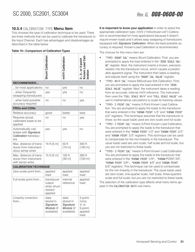
Honeywell Sensing and Control 31
SC 2000, SC2001, SC3004 Rev. G, 008-0608-00
10.5.4 CALIBRATION TYPE Menu ItemThis chooses the type of calibration technique to be used. There are three methods that can be used to calibrate the transducer to the Input Channel. Each has advantages and disadvantages as described in the table below
Table 10-: Comparison of Calibration Types
Sh
un
t C
alib
rati
on
mV
/V C
alib
rati
on
2-, 3
-, o
r 5-
po
int
Kn
ow
n L
oad
Cal
i-b
rati
on
RECOMMENDED...
...for most applications no yes no
...when frequently swapping transducers
yes yes no
...when best possible accuracy required
no no yes
PROs and CONs
Relative accuracy good better best
Requires actual, calibrated loads to be applied
no no yes
Automatically cali-brates with Signature Calibration transduc-ers
yes yes no
Max. distance of trans-ducer from instrument w/out sense wires
15 ft [5 m] 50 ft [15 m]
300 ft [100 m]
Max. distance of trans-ducer from instrument with sense wires
15 ft [5 m] 100 ft [30 m]
300 ft [100 m]
CALIBRATION TECHNIQUE
Zero-scale point from... applied load
applied load
applied load
Full-scale point from... transducer output when shunt resistor applied
internal reference
applied load
Linearity correction from...
data stored in Signature Module (if available)
data stored in Signature Module (if available)
2-point: none;3- or 5-point: applied load
It is important to know your application in order to select the appropriate calibration type. mV/V (“millivolt-per-volt”) Calibra-tion is recommended for most applications because it doesn’t require known loads and it allows easy swapping of transducers equipped with Signature Calibration. When the best possible ac-curacy is required, Known-Load Calibration is recommended.
The choices for this menu item are:
• “TYPE= SHUNT CAL” means Shunt Calibration. First, you are prompted to apply the load entered in the “ZERO SCALE VAL-UE” register. Next, the instrument inserts a known, precision resistor into the transducer circuit, which causes a predict-able apparent signal. The instrument then takes a reading and adjusts itself using the “SHUNT CAL VALUE” register.
• “TYPE= MV/V CAL” means Millivolt-per-Volt Calibration. First, you are prompted to apply the load entered in the “ZERO SCALE VALUE” register. Next, the instrument takes a reading from an accurate, internal mV/V reference. The instrument then uses the “FULL SCALE MV/V” and “FULL SCALE VALUE” val-ues in mathematical calculations to scale its tracking values.
• “TYPE= 2 POINT CAL” means 2-Point Known Load Calibra-tion. You are prompted to apply the loads to the transducer that were entered in the “KNOWN POINT 1/2” and “KNOWN POINT 2/2” registers. This technique assumes that the transducer is linear, so the usual loads used are zero scale and full scale.
• “TYPE= 3 POINT CAL” means 3-Point Known Load Calibration. You are prompted to apply the loads to the transducer that were entered in the “KNOWN POINT 1/3” and “KNOWN POINT 2/3” and “KNOWN POINT 3/3” registers. This technique can be used to compensate for the non-linearity in the transducer. The usual loads used are zero scale, half scale and full scale, but you are not restricted to these loads.
• “TYPE= 5 POINT CAL” means 5-Point Known Load Calibration. You are prompted to apply the loads to the transducer that were entered in the “KNOWN POINT 1/5”, “KNOWN POINT 2/5”, “KNOWN POINT 3/5”, “KNOWN POINT 4/5” and “KNOWN POINT 5/5” registers. This technique can be used to compensate for the non-linearity in the transducer. The usual loads used are zero scale, one-quarter scale, half scale, three-quarters scale and full scale, but you are not restricted to these loads.
The selection of the calibration type affects what menu items ap-pear in the CALIBRATION DATA sub-menu.
32 Honeywell Sensing and Control
Signal Conditioning, Self Calibrating Digital Indicators Rev. G, 008-0608-00
10.5.5 CALIBRATION DATA Sub-MenuThis enters the values that will be used by the instrument when it calibrates itself to the transducer. The menu items that are displayed will change according to what the CALIBRATION TYPE is set for.
EXCITATION Menu ItemThis sets the excitation voltage used to power up the transducer. The choice are:
• “EXCITATION=5VDC” means 5 volts dc excitation.• “EXCITATION=10VDC” means 10 volts dc excitation.NOTE: if the transducer includes a Signature Module, the excita-tion voltage of the instrument is set to 5 Vdc regardless of the value stored within the Signature Module.
FULL SCALE MV/V Menu ItemThe transducer output when its full-scale load is applied to it, in milliVolts-per-Volt. This menu item is used by the instrument to set the gain of its amplifier circuit, and (when the CALIBRATION TYPE is set to mV/V Calibration) to calibrate the instrument. This value is normally found on the transducer’s Certificate of Calibra-tion issued by its manufacturer.
This menu item may be automatically updated by a transducer’s Signature Module. It is available for all calibration types.
FULL SCALE VALUE Menu ItemThe transducer’s full-scale output in engineering units.
This menu item may be automatically updated by a transducer’s Signature Module. It is available only with the Shunt Calibration and mV/V Calibration types.
ZERO SCALE VALUE Menu ItemThe transducer’s zero-scale output in engineering units, which is usually zero.
This menu item may be automatically updated by a transducer’s Signature Module. It is available only with the Shunt Calibration and mV/V Calibration types.
SHUNT CAL VALUE Menu ItemThe shunt calibration value must be calculated by using informa-tion found on the transducer’s Certificate of Calibration and the following formula:
SHUNT CAL VALUE = Shunt-calibration output
Full-scale outputx Full-scale capacity
The terms have the following meanings:
• Shunt-CalibrationOutput:Thetransducer’soutputundershunt calibration conditions in mV/V. Sometimes called “Shunt Cal. Factor”.
• Full-ScaleOutput:Thetransducer’sfull-scaleoutputinmV/V.Sometimes called “Calibration Factor”.
• Full-ScaleCapacity:Thetransducer’sdesiredfull-scaleread-ing in engineering units (PSI, lbs, Kg, etc.). You may wish to convert the engineering units of this value. For example, if the transducer full scale is 3000PSIG and you wish the chan-nel to read in bar, you must convert 3000PSIG into 206.84 bar.
This menu item may be automatically updated by a transducer’s Signature Module.
The shunt resistor’s ohmic value used to generate the Shunt-Cal-ibration Output is given on the transducer’s Certificate of Calibra-tion. Normally, the instrument has a shunt calibration resistor of 59000 (59K) ohms installed. If your transducer and instrument were purchased at the same time from Honeywell, the correct shunt resistor has been installed.
This menu item is only available with the Shunt Calibration type.
To verify proper transducer operation, you can apply the shunt re-sistor to the transducer while the instrument is in the RUN mode. Press and hold the [ENTER] button for three seconds; this will apply the shunt resistor and display the reading.
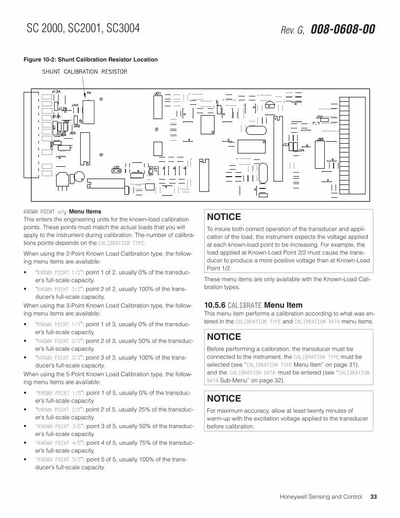
Honeywell Sensing and Control 33
SC 2000, SC2001, SC3004 Rev. G, 008-0608-00
Figure 10-2: Shunt Calibration Resistor Location
KNOWN POINT x/y Menu ItemsThis enters the engineering units for the known-load calibration points. These points must match the actual loads that you will apply to the instrument during calibration. The number of calibra-tions points depends on the CALIBRATION TYPE.
When using the 2-Point Known Load Calibration type, the follow-ing menu items are available:
• “KNOWN POINT 1/2”: point 1 of 2, usually 0% of the transduc-er’s full-scale capacity.
• “KNOWN POINT 2/2”: point 2 of 2, usually 100% of the trans-ducer’s full-scale capacity.
When using the 3-Point Known Load Calibration type, the follow-ing menu items are available:
• “KNOWN POINT 1/3”: point 1 of 3, usually 0% of the transduc-er’s full-scale capacity.
• “KNOWN POINT 2/3”: point 2 of 3, usually 50% of the transduc-er’s full-scale capacity.
• “KNOWN POINT 3/3”: point 3 of 3, usually 100% of the trans-ducer’s full-scale capacity.
When using the 5-Point Known Load Calibration type, the follow-ing menu items are available:
• “KNOWN POINT 1/5”: point 1 of 5, usually 0% of the transduc-er’s full-scale capacity.
• “KNOWN POINT 2/5”: point 2 of 5, usually 25% of the transduc-er’s full-scale capacity.
• “KNOWN POINT 3/5”: point 3 of 5, usually 50% of the transduc-er’s full-scale capacity.
• “KNOWN POINT 4/5”: point 4 of 5, usually 75% of the transduc-er’s full-scale capacity.
• “KNOWN POINT 5/5”: point 5 of 5, usually 100% of the trans-ducer’s full-scale capacity.
NOTICETo insure both correct operation of the transducer and appli-cation of the load, the instrument expects the voltage applied at each known-load point to be increasing. For example, the load applied at Known-Load Point 2/2 must cause the trans-ducer to produce a more positive voltage than at Known-Load Point 1/2.
These menu items are only available with the Known-Load Cali-bration types.
10.5.6 CALIBRATE Menu ItemThis menu item performs a calibration according to what was en-tered in the CALIBRATION TYPE and CALIBRATION DATA menu items.
NOTICEBefore performing a calibration, the transducer must be connected to the instrument, the CALIBRATION TYPE must be selected (see “CALIBRATION TYPE Menu Item” on page 31), and the CALIBRATION DATA must be entered (see “CALIBRATION DATA Sub-Menu” on page 32).
NOTICEFor maximum accuracy, allow at least twenty minutes of warm-up with the excitation voltage applied to the transducer before calibration.
34 Honeywell Sensing and Control
Signal Conditioning, Self Calibrating Digital Indicators Rev. G, 008-0608-00
If the CALIBRATION TYPE is Shunt Calibration...
• ThedisplaywillreadDOING SHUNT CAL, and prompt you to APPLY 00000 UNIT (where 00000 and UNIT are previously entered as ZERO SCALE VALUE and DISPLAY. UNITS. When you have applied this load to the transducer, press [ENTER].
• ThedisplaywillthenreadWORKING and calibration will take place. Upon completion, the display will indicate DONE and the instrument will return to the RUN mode.
If the CALIBRATION TYPE is mV/V Calibration...
• ThedisplaywillreadDOING MV/V CAL, and prompt you to APPLY 00000 UNIT (where 00000 and UNIT are previously entered as ZERO SCALE VALUE and DISPLAY. UNITS). When you have applied this load to the transducer, press [ENTER].
• ThedisplaywillthenreadWORKING and calibration will take place. Upon completion, the display will indicate DONE and the instrument will return to the RUN mode.
If the CALIBRATION TYPE is 2-Point Known Load Calibration...
• ThedisplaywillreadDOING 2POINT CAL, and prompt you to APPLY 00000 UNIT (where 00000 and UNIT are previously entered as KNOWN POINT 1/2 and DISPLAY. UNITS). When you have applied this load to the transducer, press [ENTER].
• ThedisplaywillreadWORKING, then APPLY 01000 UNIT (where 01000 and UNIT are previously entered as KNOWN POINT 2/2 and DISPLAY. UNITS). When you have applied this load to the transducer, press [ENTER].
• Uponcompletion,thedisplaywillindicateDONE and the instrument will return to the RUN mode.
If the CALIBRATION TYPE is 3-Point Known Load Calibration...
• ThedisplaywillreadDOING 3POINT CAL, and prompt you to APPLY 00000 UNIT (where 00000 and UNIT are previously entered as KNOWN POINT 1/3 and DISPLAY. UNITS). When you have applied this load to the transducer, press [ENTER].
• ThedisplaywillreadWORKING, then APPLY 00500 UNIT (where 00500 and UNIT are previously entered as KNOWN POINT 2/3 and DISPLAY. UNITS). When you have applied this load to the transducer, press [ENTER].
• ThedisplaywillreadWORKING, then APPLY 01000 UNIT (where 01000 and UNIT are previously entered as KNOWN POINT 3/3 and DISPLAY. UNITS). When you have applied this load to the transducer, press [ENTER].
• Uponcompletion,thedisplaywillindicateDONE and the instrument will return to the RUN mode.
If the CALIBRATION TYPE is 5-Point Known Load Calibration...
• ThedisplaywillreadDOING 5POINT CAL, and prompt you to APPLY 00000 UNIT (where 00000 and UNIT are previously entered as KNOWN POINT 1/5 and DISPLAY. UNITS). When you have applied this load to the transducer, press [ENTER].
• ThedisplaywillreadWORKING, then APPLY 00250 UNIT (where 00250 and UNIT are previously entered as KNOWN POINT 2/5 and DISPLAY. UNITS). When you have applied this load to the transducer, press [ENTER].
• ThedisplaywillreadWORKING, then APPLY 00500 UNIT (where 00500 and UNIT are previously entered as KNOWN POINT 3/5 and DISPLAY. UNITS). When you have applied this load to the transducer, press [ENTER].
• ThedisplaywillreadWORKING, then APPLY 00750 UNIT (where 00750 and UNIT are previously entered as KNOWN POINT 4/5 and DISPLAY. UNITS). When you have applied this load to the transducer, press [ENTER].
• ThedisplaywillreadWORKING, then APPLY 01000 UNIT (where 01000 and UNIT are previously entered as KNOWN POINT 5/5 and DISPLAY. UNITS). When you have applied this load to the transducer, press [ENTER].
• ThedisplaywillnowreadRETURN PNTS.=NO. If you press [ENTER], the display will indicate DONE and the instrument will return to the RUN mode. If you use the [UP] button and [ENTER] to select RETURN POINTS=YES, you may now apply the same loads again but in reverse order. This will allow the instrument to measure and partially eliminate any hysteresis that may be present in the transducer. After the loads have been applied again, the display will indicate DONE and the instrument will return to the RUN mode.
10.5.7 DAC SETUP Sub-MenuThis sub-menu contains four items that control the Digital-to-Ana-log Converter (DAC) output of the channel.
DAC. CHANNEL Menu ItemThis chooses which channel will drive the DAC output. Normally, the DAC located on a particular channel will be driven by that channel, but that need not be the case. For example, if several channels were assigned to load cells on a weighing platform, the sum of all channels could (mathematically) drive one channel’s DAC output.
If the DAC is set-up to be driven by its own channel’s tracking value, the Analog Output will have the frequency response speci-fied by the channel’s FREQ. RESPONSE menu item. Otherwise, the Analog Output will operate more slowly.
Honeywell Sensing and Control 35
SC 2000, SC2001, SC3004 Rev. G, 008-0608-00
DAC. SOURCE Menu ItemThis designates the data source of the channel monitored by the analog output.
The options for this menu item are:
• “TRACK” means the live tracking value of the channel. • “PEAK” means the highest value of the channel since the
peak/valley detector was last cleared.• “VALLEY” means the lowest value of the channel since the
peak/valley detector was last cleared.If the DAC is set-up to be driven by its own channel’s tracking value, the Analog Output will have the frequency response speci-fied by the channel’s FREQ. RESPONSE menu item. Otherwise, the Analog Output will operate more slowly.
DAC. ZERO-SCALE Menu ItemThis specifies what value, in engineering units, corresponds to zero output on the Analog Output.
“Zero output” might be 0 Volts, 2.5 Volts, 5 Volts, 4 mA or 12 mA depending on if the channel has a voltage or current output and how it is configured. See “Analog Output Configuration” on page 36 the for details.
If the UPDATE DAC SETUP menu item is set to “ON” and the DAC. CHANNEL menu item is set to this channel, this menu item may be automatically updated by a transducer’s Signature Module. If the UPDATE DAC SETUP menu item is “OFF”, a transducer’s Signa-ture Module will not change this menu item.
DAC. FULL-SCALE Menu ItemSpecifies what value, in engineering units, corresponds to full output on the Analog Output.
“Full output” might be 5 Volts, 10 Volts or 20 mA depending on if the channel has a voltage or current output and how it is config-ured. See “Analog Output Configuration” on page 36 for details.
If the UPDATE DAC SETUP menu item is set to “ON” and the DAC. CHANNEL menu item is set to this channel, this menu item may be automatically updated by a transducer’s Signature Module. If the UPDATE DAC SETUP menu item is “OFF”, a transducer’s Signature Module will not change this menu item.
10.5.8 SIGNATURE MODULE Sub-Menu
UPDATE SIG.MOD? Menu ItemUpdates the information stored in the transducer’s Signature Module with any new settings that is entered into the instrument with the SETUP menus. The settings that will be updated are:
• FULL SCALE MV/V
• FULL SCALE VALUE
• SHUNT CAL VALUE
• DISPLAY. UNITS
Note that changes made to the instruments display setup (such as decimal point and count-by settings) are not updated into the Signature Module.
Updating enters these new settings from the instrument into the Signature Module. If you do not update the Signature Module, connect a different transducer to the instrument and then re-connect the original transducer again, the instrument will revert to the settings that are stored inside the Signature Module.
The options for this menu item are:
• “NO” will not update the Signature Module.• “YES” will display WORKING, update the Signature Module,
then display DONE.
DEFAULT SIG.MOD? Menu ItemThis menu item will overwrite any user settings in the Signature Module with the original default settings. The Signature Module always maintains a copy of the original default settings that were created at the factory.
The options for this menu item are:
• “NO” will not restore original default settings.• “YES” will display WORKING, update the Signature Module, with
the original factory settings, then display DONE.
UPDATE DAC SETUP Menu ItemThis menu item determines whether or not the DAC. FULL SCALE and DAC. ZERO SCALE Analog Output settings are overwritten with information from a Signature Module when a new transducer is detected by the instrument.
The options for this menu item are:
• “YES” will allow a newly detected Signature Module to update the Analog Output settings.
• “NO” will not allow automatic updating of the Analog Output settings.
36 Honeywell Sensing and Control
Signal Conditioning, Self Calibrating Digital Indicators Rev. G, 008-0608-00
10.5.9 DIAGNOSTICS Sub-Menu
DAC FULL SCALE Menu ItemWhen this menu item is selected, the Analog Output of the chan-nel is forced to its full-scale output, then DAC UPDATED is displayed. This is useful when calibrating or trimming the readout connected to the Analog Output.
DAC ZERO SCALE Menu ItemWhen this menu item is selected, the Analog Output of the channel is forced to its zero-scale output, then DAC UPDATED is displayed. This is useful when calibrating or trimming the readout connected to the Analog Output.
VERSION INFO Menu ItemThis menu item displays the part number and revision level of the firmware used by this channels microprocessor.
DISPLAY ADC Menu ItemThe options for this menu item are:
• “OFF” will allow the [VALUE] button to cycle through “TK” (tracking value), “HI” (peak value) and “LO” (valley value). This is the recommended option.
• “ON” will allow the “AD” (percentage of the Analog-to-Digital converter’s full-scale digitizing capability) display source to be available along with “TK” (tracking value), “HI” (peak value) and “LO” (valley value) when the [VALUE] button is pressed on the front panel.
The Analog-to-Digital converter counts are displayed as a per-centage from -100.00% to 100.00%.
This can be used to verify that the transducer’s output does not exceed the input range of the instrument. If the Analog-to-Digital converterreadingsdisplaymorethan±10%whenthereisnoload on the transducer, the transducer has a high zero offset.
LINEARIZATION Menu ItemThe options for this menu item are:
• “ON” will allow linearization data obtained from either the Sig-nature Module or a 3-Point or 5-Point Known Load Calibra-tion to affect a channel’s scaled values. This is the recom-mended option.
• “OFF” will not allow linearization data to effect the channel’s scaled values. This is useful when diagnosing problems in a calibration procedure.
DISABLE CHANNEL Menu ItemThe options for this menu item are:
• “ON” will bypass the INITIALIZE and RUN modes of the chan-nel. The track, peak and valley values of the channel are forced to 0. This option is helpful when a channel is installed but not being used. ERROR 46, which will normally occur when the (+)Sense and (-)Sense wires are not connected properly, will be surpressed.
• “OFF” will allow normal operation of the channel.
10.6 Analog Output Configuration
10.6.1 Identifying the Output TypeA Strain-Gage Input channel is available with one of two types of digital-to-analog (DAC) outputs: voltage or current. You can de-termine which type of output a channel has by one of three ways:
• Consultingtheinstrument’sCustomerInformationSheet• ExaminingtheSYSTEM MENU -> CONFIGURATION -> CHANNEL nn
TYPE menu item where nn is the number of the channel. If the channel’s type is STRAIN GAGE V, it has a voltage output. If the channel’s type is STRAIN GAGE I, it has a current output.
• Examiningthechannel’scircuitboardasshowninthefigurebelow.
10.6.2 Channel Menu ItemsThe Analog Output can be driven by any channel’s track, peak or valley value.
See the “Channel Menu” section earlier in this chapter for a com-plete listing of SETUP menu items available on the DAC. SETUP sub-menu.
10.6.3. Output SelectionJumpers located on the channel’s circuit board determine what outputs are generated when the value selected to drive the Ana-log Output (from the DAC. CHANNEL and DAC. SOURCE menu items) equals the DAC. FULL SCALE and DAC. ZERO SCALE settings.
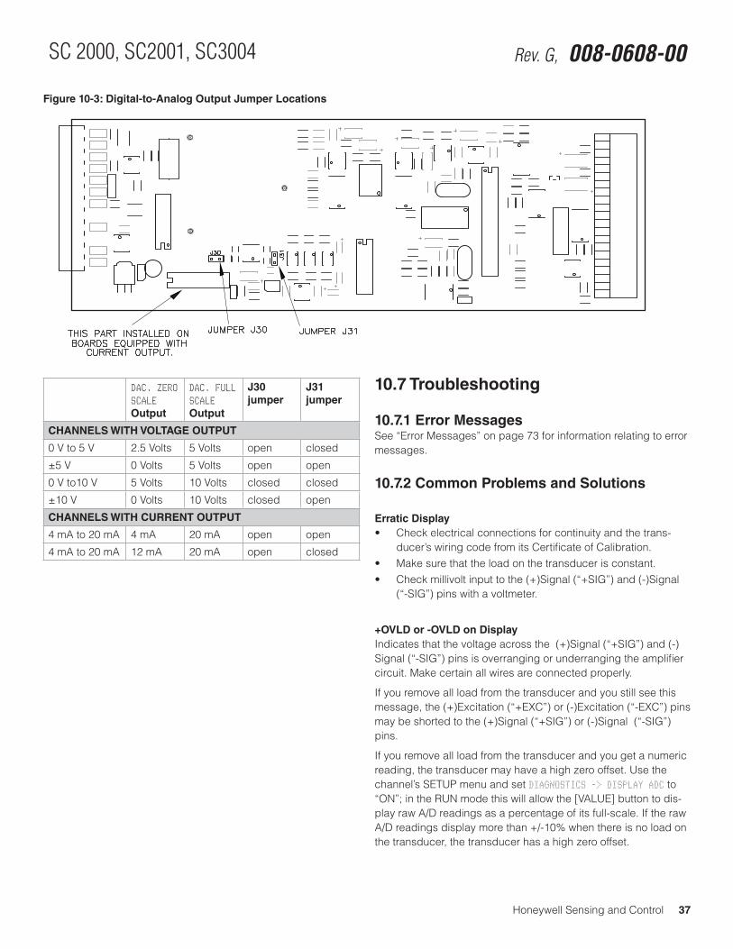
Honeywell Sensing and Control 37
SC 2000, SC2001, SC3004 Rev. G, 008-0608-00
10.7 Troubleshooting
10.7.1 Error MessagesSee “Error Messages” on page 73 for information relating to error messages.
10.7.2 Common Problems and Solutions
Erratic Display• Checkelectricalconnectionsforcontinuityandthetrans-
ducer’s wiring code from its Certificate of Calibration.• Makesurethattheloadonthetransducerisconstant.• Checkmillivoltinputtothe(+)Signal(“+SIG”)and(-)Signal
(“-SIG”) pins with a voltmeter.
+OVLD or -OVLD on DisplayIndicates that the voltage across the (+)Signal (“+SIG”) and (-)Signal (“-SIG”) pins is overranging or underranging the amplifier circuit. Make certain all wires are connected properly.
If you remove all load from the transducer and you still see this message, the (+)Excitation (“+EXC”) or (-)Excitation (“-EXC”) pins may be shorted to the (+)Signal (“+SIG”) or (-)Signal (“-SIG”) pins.
If you remove all load from the transducer and you get a numeric reading, the transducer may have a high zero offset. Use the channel’s SETUP menu and set DIAGNOSTICS -> DISPLAY ADC to “ON”; in the RUN mode this will allow the [VALUE] button to dis-play raw A/D readings as a percentage of its full-scale. If the raw A/D readings display more than +/-10% when there is no load on the transducer, the transducer has a high zero offset.
Figure 10-3: Digital-to-Analog Output Jumper Locations
DAC. ZERO SCALE Output
DAC. FULL SCALE Output
J30 jumper
J31 jumper
CHANNELS WITH VOLTAGE OUTPUT
0 V to 5 V 2.5 Volts 5 Volts open closed
±5V 0 Volts 5 Volts open open
0 V to10 V 5 Volts 10 Volts closed closed
±10V 0 Volts 10 Volts closed open
CHANNELS WITH CURRENT OUTPUT
4 mA to 20 mA 4 mA 20 mA open open
4 mA to 20 mA 12 mA 20 mA open closed
38 Honeywell Sensing and Control
Signal Conditioning, Self Calibrating Digital Indicators Rev. G, 008-0608-00
Analog Output IncorrectMake certain of the type of Analog Output (voltage or current) that the channel is equipped with; see “Identifying the Output Type” on page 36.
Use the DIAGNOSTICS -> DAC FULL SCALE and DIAGNOSTICS -> DAC ZERO SCALE menu items to force the Analog Output to a known output. Then, adjust your readout device, panel meter, PLC or data acquisition system to match.
Check the output selection jumpers; see “Output Selection” on page 36.
“APPLY 00000” on Power-upThe channel has detected that the transducer connected to the instrument is different than the one the channel was last calibrat-ed with. Because the CALIBRATION TYPE is set to either Shunt Cali-bration or mV/V Calibration, the instrument is prompting you to apply zero load in order to auto-calibrate to this new transducer.
Do one of the following, depending on the situation:
• Re-connecttheoriginaltransducertothechannelandre-start the instrument.
• Press[ENTER]tore-calibratethechanneltothisnewtransducer using Shunt or mV/V Calibration and accept the presently applied load as “0”. (In situations where one can’t apply “0” load to an absolute pressure transducer or a load cell with a pre-load, you can change the CALIBRATION DATA -> ZERO-SCALE VALUE menu item from “0” to a load that can be applied. For example, 14.7 PSIA or the known pre-load on the load cell.
• UsetheCALIBRATE menu item to perform a Known-Load Cali-bration with this new transducer.
Auxiliary Function Pins Not OperatingMake sure that the AUX1 FUNCTION or AUX2 FUNCTION SETUP menu items are set correctly; if they are set to DISABLED then they will not operate.
The Auxiliary Function (“AUX1” and “AUX2”) pins must be con-nected to pin 10, not pin 8, to activate them.
Sensitivity to EMI/RFITo obtain maximum immunity to electromagnetic or radio frequen-cy interference, make certain that the shields of the transducer cables are connected to the “cable shield connection screw” on the rear panel of the instrument. See “Unamplified Transducer Connection to Strain-Gage Input Channel” on page 27, “External Arrangement of AC powered SC2000” on page 10 and “External Arrangement of Model SC3004” on page 15.
Shunt Calibration Feature not OperatingTo activate the channel’s shunt calibration function while the in-strument is in RUN Mode, see “Shunt Calibration Check” on page 7. This serves as a quick check of the shunt cal feature.
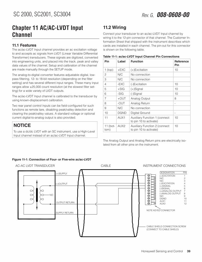
Honeywell Sensing and Control 39
SC 2000, SC2001, SC3004 Rev. G, 008-0608-00
Chapter 11 AC/AC-LVDT Input Channel
11.1 FeaturesThe ac/ac-LVDT Input channel provides an ac excitation voltage to and accepts ac signals from LVDT (Linear Variable Differential Transformer) transducers. These signals are digitized, converted into engineering units, and placed into the track, peak and valley data values of the channel. Setup and calibration of the channel are made manually through the SETUP mode.
The analog-to-digital converter features adjustable digital, low-pass filtering, 12- to 18-bit resolution (depending on the filter setting) and has several different input ranges. These many input rangesallow±25,000countresolution(attheslowestfilterset-ting) for a wide variety of LVDT outputs.
The ac/ac-LVDT Input channel is calibrated to the transducer by using known-displacement calibration.
Two rear panel control inputs can be field-configured for such functions as remote tare, disabling peak/valley detection and clearing the peak/valley values. A standard voltage or optional current digital-to-analog output is also provided.
NOTICETo use a dc/dc LVDT with an SC instrument, use a High-Level Input channel instead of an ac/ac-LVDT Input channel.
11.2 Wiring Connect your transducer to an ac/ac-LVDT Input channel by wiring it to the 12-pin connector of that channel. The Customer In-formation Sheet that shipped with the instrument describes which cards are installed in each channel. The pin-out for this connector is shown on the following table.
Table 11-1: ac/ac-LVDT Input Channel Pin Connections
Pin Label Function Reference Pin
1 (top) +EXC (+)Excitation 10
2 N/C No connection
3 N/C No connection
4 -EXC (-)Excitation 10
5 +SIG (+)Signal 10
6 -SIG (-)Signal 10
7 +OUT Analog Output 8
8 -OUT Analog Return -
9 N/C No connection
10 DGND Digital Ground -
11 AUX1 Auxiliary Function 1 (connect to pin 10 to activate)
10
11 (bot-tom)
AUX2 Auxiliary Function 2 (connect to pin 10 to activate)
10
The Analog Output and Analog Return pins are electrically iso-lated from all other pins on the instrument.
Figure 11-1: Connection of Four- or Five-wire ac/ac-LVDT
123456789101112
(+)EXCITATIONN/CN/C(-)EXCITATION(+)SIGNAL(-)SIGNAL(+)ANALOG OUTPUT(-)ANALOG OUTPUTN/CDGNDAUX1AUX2
DESIGNATION PIN
CABLE SHIELD CONNECTION SCREW
(+)SUPPLY
SUPPLY RETURN
(+)OUTPUT
OUTPUT RETURN
AC-AC LVDT TRANSDUCER CABLE INSTRUMENT CONNECTIONS
(CONNECT TO CABLE SHIELD)
N/C
NOTE KEYED CONNECTOR
40 Honeywell Sensing and Control
Signal Conditioning, Self Calibrating Digital Indicators Rev. G, 008-0608-00
11.3 Calibration ProcedureIf you are not familiar with operating the instrument in the SETUP menu mode, see “SETUP Menu mode” on page 7. A listing of all menu items is given in “Setup Menu Reference” on page 77.
• Step1:Wirethetransducertothechannel’sconnector. See “Wiring” on page 39 for details.
• Step2:EntertheCALIBRATION TYPE. You must have the capability to apply either two, three, or
five known displacements to the transducer. The CALIBRA-TION TYPE menu item allows you to specify how many known displacements will be applied during calibration.
• Step3:EntertheCALIBRATION DATA. Consult the Certificate of Calibration for the transducer when
entering information in the CALIBRATION DATA sub-menu.
• Step4:DeterminetheLVDT’selectricalnullpoint,thenphysi-cally mount it.
The electrical null is the armature position that produces the least electrical output. Once this point has been determined, the transducer is physically clamped into position. See “Electrical Null and Transducer Mounting” on page 45.
• Step5:Performthecalibration. Using the CALIBRATE menu item starts the calibration pro-
cess. You will be prompted to apply displacements to the transducer as required.
11.4 Specifications
TRANSDUCER INPUT
Transducer type full-bridge, AC/AC-LVDT
Excitation Voltage 3 V RMS @ 5kHz, short circuit pro-tected
Transducer full-scale output
0.1 to 15 V RMS @ 3 V RMS excita-tion
Amplifier gain selection automatic
Calibration type 2-, 3- or 5- point known displace-ment
A/D converter 24-bit Sigma-Delta
Low-pass filter digital, 24-tap FIR
Resolution see page 41
Frequency response see page 41
AUXILLARY INPUTS
Quantity 2
Type momentary contact closure
Response time < 5 ms
Field-selectable func-tions
tare on, tare off, peak/valley clear, peak/valley hold, track hold
ANALOG OUTPUTS
Voltage range (voltage output channels)
5,±5,10or±10Vdc
Current range (current output channels)
4 mA to 20 mA
Source any channel’s track, peak, or valley value
Isolation 500 V
Resolution 13 bits
Frequency response same as input when driven by the same channel’s tracking data
Honeywell Sensing and Control 41
SC 2000, SC2001, SC3004 Rev. G, 008-0608-00
11.5 Channel MenuEach ac/ac-LVDT Input channel is configured and calibrated via its channel menu. Detailed instructions on operating the instru-ment in the SETUP Menu mode can be found in “SETUP Menu mode” on page 7. A diagram of all menus is located in “Setup Menu Reference” on page 77.
11.5.1 OPERATION Sub-MenuThis menu controls the operation of this channel when the instru-ment is in the RUN mode.
AUTO-ZERO Menu ItemThis enables or disables the channel’s automatic zeroing func-tion. When enabled, the channel will reset its tracking value to zero when the tracking value is less than 10 display counts for a period of 10 seconds. This removes the effect of slight tempera-ture shifts in the transducer’s output.
NOTICETo compensate for the transducer’s initial warm-up shift, the auto-zero function operates every 2 seconds during the first 60 seconds of RUN mode operation.
The two options for this menu item are “ON” and “OFF”.
FREQ. RESPONSE Menu ItemThis sets the frequency response, step response, and resolution of the channel according to the table below. The tracking value, peak/valley detector values and analog output on this channel are all affected. The default value of 016. HERTZ is suitable for most applications.
Frequency Response
Step Response (ms) (typical)
Resolution (counts) (not including min. 10% overrange/underrange capability)
002. HERTZ/FAST
40 ±25000
002. HERTZ 440 ±25000
008. HERTZ 110 ±15000
016. HERTZ 55 ±10000
032. HERTZ 28 ±10000
050. HERTZ 16 ±5000
100. HERTZ 8 ±5000
250. HERTZ 3 ±2000
500. HERTZ 2 ±2000
800. HERTZ 2 ±2000
NOTICEYour particular LVDT may have a lower frequency response than the ac-ac LVDT Input channel.
POWER-ON SOURCE Menu ItemThis menu selects which value is displayed by the channel when first entering the RUN mode.
The choices are:
• “TRACK” means the live tracking value of the channel. • “PEAK” means the highest value of the channel.• “VALLEY” means the lowest value of the channel.• “TRACK / PEAK” means the live tracking value and the highest
value of the channel. (Only available on Model SC3004).• “TRACK / VALLEY” means the live tracking value and the low-
est value of the channel. (Only available on Model SC3004).• “PEAK / VALLEY” means the highest and lowest values of the
channel. (Only available on Model SC3004).
11.5.2 DISPLAY SETUP Sub-MenuThis menu controls how data values are displayed by the channel and transmitted via serial communications.
DISPLAY. DIGITS Menu ItemSelects the number of digits displayed by the channel. The choices are:
• “5 DIGIT-BIPOLAR” displays both positive and negative num-berswithfivefulldigits(±99999).
• “6 DIGIT-UNIPOLAR” displays positive numbers with six full digits (999999) and negative numbers with five full digits (-99999).
• “7 DIGIT UNIPOLAR” displays positive number with seven full digits (9999999) and negative numbers with six digits (-999999).
DISPLAY. DECPT Menu ItemSelects the decimal point location on the channel’s display and serial communications output. Use the [UP] and [DOWN] buttons to move the decimal point to the right and left.
DISPLAY. COUNT-BY Menu ItemDetermines by what value the display increments or decrements. This will make the display less sensitive to a noisy signal. The choices are:
• “00001”
• “00002”
• “00005”
• “00010”
• “00020”
• “00050”
• “00100”
• “00200”
42 Honeywell Sensing and Control
Signal Conditioning, Self Calibrating Digital Indicators Rev. G, 008-0608-00
DISPLAY. UNITS Menu ItemSpecifies the four character label that is displayed to the right of the channel’s values.
NOTICEThis menu item doesn’t change the mathematical scaling of the channel’s values; that can be changed by altering the “CALIBRATION DATA -> KNOWN POINT X/Y” menu items and then performing a re-calibration.
When a character position is flashing press the [UP] or [DOWN] button to change the character. Press [ENTER] to advance to the next character.
DISPLAY. AVERAGE Menu ItemControls the speed with which the channel’s display values will update. Display averaging does not affect the channel’s analog output or its peak/valley detection, which will proceed at the speed selected by the ”OPERATION -> FREQ. RESPONSE” menu item. The choices are:
• “ON” means that the display will update four times each sec-ond. The channel’s values will be averaged for 1/4 second, then displayed.
• “OFF” means that the channel’s display will update as quickly as possible.
11.5.3 AUXn FUNCTION Menu ItemsThe AUX1 FUNCTION and AUX2 FUNCTION menu items determine what happens when the Auxiliary Function pins (labeled as “AUX1” and “AUX2”) on the channel’s connector are activated. These pins are “activated” when they are connected to the DGND pin. The choices are:
• “DISABLED” means that activating the pin does nothing.• “TRACK HOLD” means that the tracking, peak and valley values
will not be updated.• “HIGH/LOW HOLD” means that the peak and valley values will
not be updated.• “HIGH/LOW CLEAR” means that the peak and valley values are
reset. • “TARE ON” activates the channel’s Tare function (resets it to
zero).• “TARE OFF” deactivates the channel’s Tare function.As the Auxiliary Function pins are not isolated, it is recommended that a push-button switch or relay is used to connect these pins to the DGND pin.
11.5.4 CALIBRATION TYPE Menu ItemThe choices for this menu item are:
• “TYPE= 2 POINT CAL” means 2-Point Known Displacement Calibration. You are prompted to apply the displacements to the transducer that were entered in the “KNOWN POINT 1/2” and “KNOWN POINT 2/2” registers. This technique assumes that the transducer is linear throughout the entire stroke, so the usual displacements used are zero scale and full scale.
• “TYPE= 3 POINT CAL” means 3-Point Known Displacement Calibration. You are prompted to apply the displacements to the transducer that were entered in the “KNOWN POINT 1/3” and “KNOWN POINT 2/3” and “KNOWN POINT 3/3” registers. This technique can be used to compensate for the different sen-sitivities that an LVDT may have on each side of its electrical null. The usual displacements used are zero scale, half scale and full scale, but you are not restricted to these displace-ments.
• “TYPE= 5 POINT CAL” means 5-Point Known Displacement Calibration. You are prompted to apply the displacements to the transducer that were entered in the “KNOWN POINT 1/5”, “KNOWN POINT 2/5”, “KNOWN POINT 3/5”, “KNOWN POINT 4/5” and “KNOWN POINT 5/5” registers. This technique can be used to compensate for the non-linearity in the transducer as well as the different sensitivities on each side of its electrical null. The usual displacements used are zero scale, one-quarter scale, half scale, three-quarters scale and full scale, but you are not restricted to these displacements.
The selection of the calibration type affects what menu items ap-pear in the CALIBRATION DATA sub-menu.
11.5.5. CALIBRATION DATA Sub-MenuThis sub-menu enters the values that will be used by the instru-ment when it calibrates itself to the transducer. The menu items that are displayed will change according to what the CALIBRATION TYPE is set for.
FULL SCALE VRMS Menu ItemThe transducer output when its full-scale displacement is applied to it, in Volts RMS (root-mean-squared) assuming 3 VRMS excita-tion. This menu item is used by the instrument to set gain of its amplifier circuit. This value is normally found on the transducer’s Certificate of Calibration issued by its manufacturer.
Honeywell Sensing and Control 43
SC 2000, SC2001, SC3004 Rev. G, 008-0608-00
KNOWN POINT x/y Menu ItemsThis enters the engineering units for the known-displacement calibration points. These points must match the actually dis-placements that you will apply to the transducer during calibra-tion. The number of calibrations points depends on the CALIBRA-TION TYPE.
When using the 2-Point Known Displacement Calibration type, the following menu items are available:
• “KNOWN POINT 1/2”: point 1 of 2, usually 0% of the transduc-er’s full-scale capacity.
• “KNOWN POINT 2/2”: point 2 of 2, usually 100% of the trans-ducer’s full-scale capacity.
When using the 3-Point Known Displacement Calibration type, the following menu items are available:
• “KNOWN POINT 1/3”: point 1 of 3, usually 0% of the transduc-er’s full-scale capacity.
• “KNOWN POINT 2/3”: point 2 of 3, usually 50% of the transduc-er’s full-scale capacity.
• “KNOWN POINT 3/3”: point 3 of 3, usually 100% of the trans-ducer’s full-scale capacity.
When using the 5-Point Known Displacement Calibration type, the following menu items are available:
• “KNOWN POINT 1/5”: point 1 of 5, usually 0% of the transduc-er’s full-scale capacity.
• “KNOWN POINT 2/5”: point 2 of 5, usually 25% of the transduc-er’s full-scale capacity.
• “KNOWN POINT 3/5”: point 3 of 5, usually 50% of the transduc-er’s full-scale capacity.
• “KNOWN POINT 4/5”: point 4 of 5, usually 75% of the transduc-er’s full-scale capacity.
• “KNOWN POINT 5/5”: point 5 of 5, usually 100% of the trans-ducer’s full-scale capacity.
NOTICETo insure both correct operation of the transducer and ap-plication of the displacement, the instrument expects the voltage applied at each known-displacement point to be increasing. For example, the displacement applied at Known-Displacement Point 2/2 must cause the transducer to produce a more positive voltage than at Known-Displacement Point 1/2. You may need to swap the (+)Signal and (-)Signal wires on the 12-pin channel connector to accomplish this.
11.5.6 CALIBRATE Menu ItemThis menu item performs a calibration according to what was en-tered in the CALIBRATION TYPE and CALIBRATION DATA menu items.
NOTICEBefore performing a calibration, the transducer must be connected to the instrument, the must be selected (see “ Menu Item” on page 42) and the must be entered (see “ Sub-Menu” on page 42).
NOTICEFor maximum accuracy, allow at least twenty minutes of warm-up with the excitation voltage applied to the transducer before calibration.
If the CALIBRATION TYPE is 2-Point Known Displacement Cali-bration...• ThedisplaywillreadDOING 2POINT CAL, and prompt you to
APPLY 00000 UNIT (where 00000 and UNIT are previously entered as KNOWN POINT 1/2 and DISPLAY. UNITS). When you have applied this displacement to the transducer, press [ENTER].
• ThedisplaywillreadWORKING, then APPLY 01000 UNIT (where 01000 and UNIT are previously entered as KNOWN POINT 2/2 and DISPLAY. UNITS). When you have applied this displace-ment to the transducer, press [ENTER].
• Uponcompletion,thedisplaywillindicateDONE and the instrument will return to the RUN mode.
If the CALIBRATION TYPE is 3-Point Known Displacement Cali-bration...• Thedisplaywillread DOING 3POINT CAL, and prompt you to
APPLY 00000 UNIT (where 00000 and UNIT are previously entered as KNOWN POINT 1/3 and DISPLAY. UNITS). When you have applied this displacement to the transducer, press [ENTER].
• ThedisplaywillreadWORKING, then APPLY 00500 UNIT (where 00500 and UNIT are previously entered as KNOWN POINT 2/3 and DISPLAY. UNITS). When you have applied this displace-ment to the transducer, press [ENTER].
• ThedisplaywillreadWORKING, then APPLY 01000 UNIT (where 01000 and UNIT are previously entered as KNOWN POINT 2/3 and DISPLAY. UNITS). When you have applied this displace-ment to the transducer, press [ENTER].
• Uponcompletion,thedisplaywillindicateDONE and the instrument will return to the RUN mode.
44 Honeywell Sensing and Control
Signal Conditioning, Self Calibrating Digital Indicators Rev. G, 008-0608-00
If the CALIBRATION TYPE is 5-Point Known Displacement Cali-bration...• ThedisplaywillreadDOING 5POINT CAL, and prompt you to
APPLY 00000 UNIT (where 00000 and UNIT are previously entered as KNOWN POINT 1/5 and DISPLAY. UNITS). When you have applied this displacement to the transducer, press [ENTER].
• ThedisplaywillreadWORKING, then APPLY 00250 UNIT (where 00250 and UNIT are previously entered as KNOWN POINT 2/5 and DISPLAY. UNITS). When you have applied this displace-ment to the transducer, press [ENTER].
• Thedisplaywillread WORKING, then APPLY 00500 UNIT (where 00500 and UNIT are previously entered as KNOWN POINT 3/5 and DISPLAY. UNITS). When you have applied this displace-ment to the transducer, press [ENTER].
• ThedisplaywillreadWORKING, then APPLY 00750 UNIT (where 00750 and UNIT are previously entered as KNOWN POINT 4/5 and DISPLAY. UNITS). When you have applied this displace-ment to the transducer, press [ENTER].
• ThedisplaywillreadWORKING, then APPLY 01000 UNIT (where 01000 and UNIT are previously entered as KNOWN POINT 5/5 and DISPLAY. UNITS). When you have applied this displace-ment to the transducer, press [ENTER].
• Uponcompletion,thedisplaywillindicateDONEandtheinstrument will return to the RUN mode.
11.5.7 DAC SETUP Sub-MenuThis sub-menu contains four items that control the Digital-to-Ana-log (DAC) output of the channel.
DAC. CHANNEL Menu ItemThis chooses which channel will drive the DAC output. Normally, the DAC located on a particular channel will be driven by that channel, but that need not be the case. For example, if several channels were assigned to various transducers in a system, the sum of all channels could (mathematically) drive one channel’s DAC output.
If the DAC is set-up to be driven by its own channel’s tracking value, the Analog Output will have the frequency response speci-fied by the channel’s FREQ. RESPONSE menu item. Otherwise, the Analog Output will operate more slowly.
DAC. SOURCE Menu ItemThis designates the data source of the channel monitored by the analog output. Each channel has three data sources: the live tracking value (TRACK), its highest value (PEAK), and its lowest value (VALLEY).
The options for this menu item are:
• “TRACK” means the live tracking value of the channel. • “PEAK” means the highest value of the channel since the
peak/valley detector was last cleared.• “VALLEY” means the lowest value of the channel since the
peak/valley detector was last cleared.If the DAC is set-up to be driven by its own channel’s tracking value, the Analog Output will have the frequency response speci-fied by the channel’s FREQ. RESPONSE menu item. Otherwise, the Analog Output will operate more slowly.
DAC. ZERO-SCALE Menu ItemThis specifies what value, in engineering units, corresponds to zero output on the Analog Output.
“Zero output” might be 0 Volts, 2.5 Volts, 5 Volts, 4 mA or 12 mA depending on if the channel has a voltage or current output and how it is configured. See “Analog Output Configuration” on page 46 for details.
DAC. FULL-SCALE Menu ItemThis specifies what value, in engineering units, corresponds to full output on the Analog Output.
“Full output” might be 5 Volts, 10 Volts or 20 mA depending on if the channel has a voltage or current output and how it is config-ured. See “Analog Output Configuration” on page 46 for details.
11.5.8 DIAGNOSTICS Sub-MenuDAC FULL SCALE Menu ItemWhen this menu item is selected, the Analog Output of the chan-nel is forced to its full-scale output, then DAC UPDATED is displayed. This is useful when calibrating or trimming the readout connected to the Analog Output.
DAC ZERO SCALE Menu ItemWhen this menu item is selected, the Analog Output of the channel is forced to its zero-scale output, then DAC UPDATED is displayed. This is useful when calibrating or trimming the readout connected to the Analog Output.
Honeywell Sensing and Control 45
SC 2000, SC2001, SC3004 Rev. G, 008-0608-00
VERSION INFO Menu ItemThis menu item displays the part number and revision level of the firmware used by this channels microprocessor.
DISPLAY ADC Menu ItemThe options for this menu item are:
• “OFF” will allow the [VALUE] button to cycle through “TK” (tracking value), “HI” (peak value) and “LO” (valley value). This is the recommended option.
• “ON” will allow the “AD” (percentage of the Analog-to-Digital converter’s full-scale digitizing capability) display source to be available along with “TK” (tracking value), “HI” (peak value) and “LO” (valley value) when the [VALUE] button is pressed on the front panel.
The Analog-to-Digital converter counts are displayed as a per-centage from -100.00% to 100.00%.
This can be used to establish the transducer’s electrical null prior to mounting. See “Electrical Null and Transducer Mounting” on page 45 for this procedure.
LINEARIZATION Menu ItemThe options for this menu item are:
• “ON” will allow linearization data obtained from a 3-Point or 5-Point Known Displacement Calibration to affect a channel’s scaled values. This is the recommended option.
• “OFF” will not allow linearization data to effect the channel’s scaled values.
DISABLE CHANNEL Menu ItemThe options for this menu item are:
• “ON” will bypass the INITIALIZE and RUN modes of the chan-nel. The track, peak and valley values of the channel are forced to 0.
• “OFF” will allow normal operation of the channel.
11.6 Electrical Null and Transducer Mounting
11.6.1 OverviewThe mechanical travel of an LVDT transducer is not the same as its usable measuring range. All LVDTs exhibit some non-linearity near the ends of its armature’s mechanical travel. To insure that the LVDT will be used in its linear measuring range, its electri-cal null point must be determined. This electrical null point is the armature position which produces the minimal electrical signal output. After electrical null has been established, the LVDT is clamped down into final position in its mounting fixture.
As long as the LVDT remains clamped in this position, you do not need to re-establish the electrical null prior to every calibration.
11.6.2 Procedure
• Step1:Usethechannel’sSETUPmenuandsetDIAGNOSTICS -> DISPLAY ADC to “ON”. Exit the SETUP menu and re-start the instrument.
• Step2:DisplaythechanneltowhichtheLVDTisconnected.Press and release the [VALUE] button until the “AD” display source is shown. This is the raw analog-to-digital converter readings displayed as a percentage of its full-scale (-100% to +100%).
• Step3:MovetheLVDT’sarmaturetothepositionwhichdisplays the lowest value of raw analog-to-digital converter readings (i.e. a number close to 00.000%. This is the LVDT’s electrical null.
• Step4:FirmlyclampdowntheLVDT’sbody.• Step5:MovetheLVDT’sarmaturetoroughlytheposition
you wish to define as “positive full scale”. If the displayed analog-to-digital converter reading is a negative value, you must swap the wires connected to the (+)Signal and (-)Signal pins (labeled as “+SIG” and “-SIG”) on the channel’s 12-pin connector to make the reading positive.
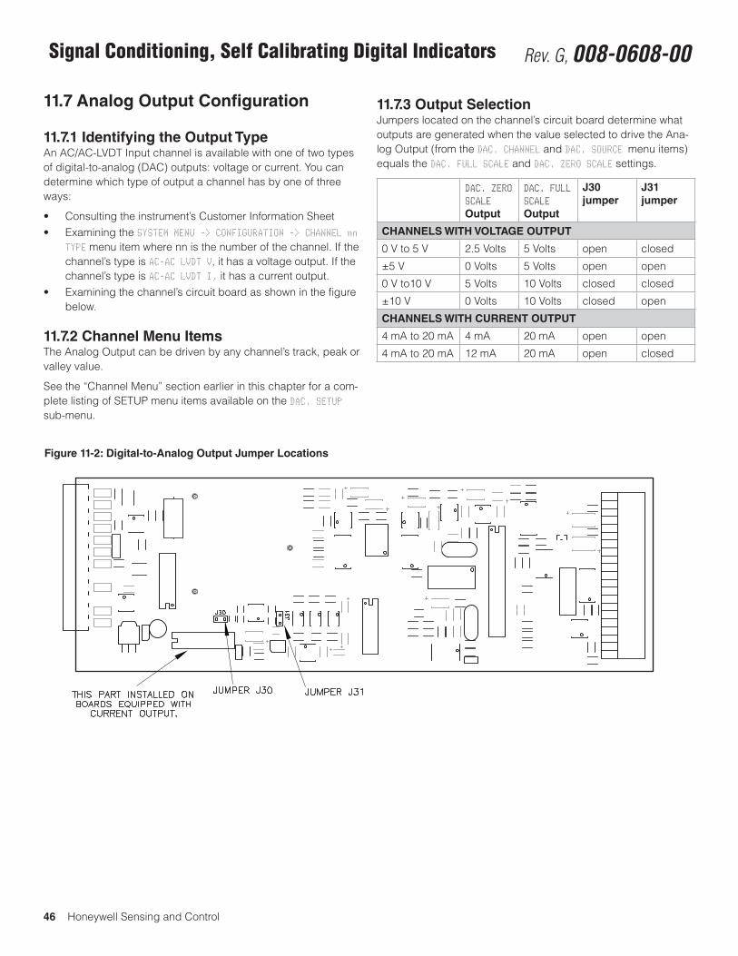
46 Honeywell Sensing and Control
Signal Conditioning, Self Calibrating Digital Indicators Rev. G, 008-0608-00
11.7 Analog Output Configuration
11.7.1 Identifying the Output TypeAn AC/AC-LVDT Input channel is available with one of two types of digital-to-analog (DAC) outputs: voltage or current. You can determine which type of output a channel has by one of three ways:
• Consultingtheinstrument’sCustomerInformationSheet• ExaminingtheSYSTEM MENU -> CONFIGURATION -> CHANNEL nn
TYPE menu item where nn is the number of the channel. If the channel’s type is AC-AC LVDT V, it has a voltage output. If the channel’s type is AC-AC LVDT I, it has a current output.
• Examiningthechannel’scircuitboardasshowninthefigurebelow.
11.7.2 Channel Menu ItemsThe Analog Output can be driven by any channel’s track, peak or valley value.
See the “Channel Menu” section earlier in this chapter for a com-plete listing of SETUP menu items available on the DAC. SETUP sub-menu.
11.7.3 Output SelectionJumpers located on the channel’s circuit board determine what outputs are generated when the value selected to drive the Ana-log Output (from the DAC. CHANNEL and DAC. SOURCE menu items) equals the DAC. FULL SCALE and DAC. ZERO SCALE settings.
Figure 11-2: Digital-to-Analog Output Jumper Locations
DAC. ZERO SCALE Output
DAC. FULL SCALE Output
J30 jumper
J31 jumper
CHANNELS WITH VOLTAGE OUTPUT
0 V to 5 V 2.5 Volts 5 Volts open closed
±5V 0 Volts 5 Volts open open
0 V to10 V 5 Volts 10 Volts closed closed
±10V 0 Volts 10 Volts closed open
CHANNELS WITH CURRENT OUTPUT
4 mA to 20 mA 4 mA 20 mA open open
4 mA to 20 mA 12 mA 20 mA open closed
Honeywell Sensing and Control 47
SC 2000, SC2001, SC3004 Rev. G, 008-0608-00
11.8 Troubleshooting
11.8.1 Error MessagesSee “Error Messages” on page 73 for information relating to error messages.
11.8.2 Common Problems and SolutionsErratic Display• Checkelectricalconnectionsforcontinuityandthetrans-
ducer’s wiring code from its Certificate of Calibration.• Makesurethatthedisplacementonthetransduceriscon-
stant.• Checktheinputtothe(+)Signal(“+SIG”)and(-)Signal(“-
SIG”) pins with an RMS voltmeter in its “AC Voltage” mode. Using a voltmeter in its dc Voltage mode will always display 0.
+OVLD or -OVLD on Display• Indicatesthatthevoltageacrossthe(+)Signal(“+SIG”)and
(-)Signal (“-SIG”) pins is overranging or underranging the amplifier circuit. Make certain all wires are connected prop-erly, the “CALIBRATION DATA -> FULL SCALE VRMS” menu item is set correctly, and that a calibration has been performed per “Calibration Procedure” on page 40.
• Ifyoumovethearmaturebacktoitselectricalnullpointandyou still see this message, the (+)Excitation (“+EXC”) or (-)Excitation (“-EXC”) pins may be shorted to the (+)Signal (“+SIG”) or (-)Signal (“-SIG”) pins.
Analog Output Incorrect• MakecertainofthetypeofAnalogOutput(voltageorcur-
rent) that the channel is equipped with; see “Identifying the Output Type” on page 46.
• UsetheDIAGNOSTICS -> DAC FULL SCALE and DIAGNOSTICS -> DAC ZERO SCALE menu items to force the Analog Output to a known output. Then, adjust your readout device, panel meter, PLC or data acquisition system to match.
• Checktheoutputselectionjumpers;see“OutputSelection”on page 46.
Auxiliary Function Pins Not Operating• MakesurethattheAUX1 FUNCTION or AUX2 FUNCTION SETUP
menu items are set correctly; if they are set to DISABLED then they will not operate.
• TheAuxiliaryFunction(“AUX1”and“AUX2”)pinsmustbeconnected to pin 10, not pin 8, to activate them.
Sensitivity to EMI/RFITo obtain maximum immunity to electromagnetic or radio frequen-cy interference, make certain that the shields of the transducer cables are connected to the “cable shield connection screw” on the rear panel of the instrument. See “Connection of Four- or Five-wire AC/AC-LVDT” on page 39, “External Arrangement of AC powered SC2000” on page 10 and “External Arrangement of Model SC3004” on page 15.
Non-linearity at the end of the LVDT’s mechanical rangeMost LVDTs have a usable measuring range that is smaller than their mechanical range. See “Electrical Null and Transducer Mounting” on page 45 for information on establishing the LVDT’s electrical null point to insure that the LVDT will be operated in its usable measuring range.
48 Honeywell Sensing and Control
Signal Conditioning, Self Calibrating Digital Indicators Rev. G, 008-0608-00
Chapter 12 High-Level Input Channel
12.1 FeaturesThe High-Level Input channel provides a dc supply voltage to and accepts voltage or current signals from amplified transduc-ers such as pressure transducers, load cells and dc-dc LVDTs. These signals are digitized, converted into engineering units, and placed into the track, peak and valley data values of the channel. Setup and calibration of the channel is made manually through the SETUP menu mode. Signature Calibration is not available with amplified transducers.
The analog-to-digital converter input circuit features adjustable digital, low-pass filtering, 12- to 18-bit resolution (depending on the filter setting) and has several different input ranges. These manyrangesallow±50,000countresolution(attheslowestfiltersetting) across a wide variety of input ranges.
A combination of SETUP menu items and hardware jumpers are used to configure the excitation supply output voltage (+28 Vdc, ±15Vdc,+15Vdcor+12Vdc),theinputtype(voltageorcurrent)and input reference (differential or single ended).
Two methods of calibrating the High-Level Input channel to the transducer are available: known-load calibration and shunt cali-bration. The benefits of each are discussed in “CALIBRATION TYPE Menu Item” on page 59.
Two rear panel control inputs can be field-configured for such functions as remote tare, disabling peak/valley detection and clearing the peak/valley values. A voltage or current digital-to-analog output is also provided.
12.2 Wiring
12.2.1 Channel ConnectorConnect the amplified transducer, in-line amplifier or dc-dc LVDT to a High-Level Input channel by wiring it to the 12-pin connec-tor of that channel. The Customer Information Sheet that shipped with the instrument describes which cards are installed in each channel. The pin-out for this connector is shown on the following table.
Table 12-1: High-Level Input Channel Pin Connections
Pin Label Function Ref. Pin
1 (top) +EXC (+)Excitation 10
2 SHUNT1 Shunt Cal Relay 3
3 -SHUNT2 Shunt Cal Relay 2
4 -EXC (-)Excitation 10
5 +SIG (+)Signal 10
6 -SIG (-)Signal 10
7 +OUT Analog Output 8
8 -OUT Analog Return -
9 N/C No Connection -
10 DGND Digital Ground -
11 AUX1 Auxiliary Function 1 (connect to pin 10 to activate)
10
12 (bot-tom)
AUX2 Auxiliary Function 2 (connect to pin 10 to activate)
10
The Analog Output and Analog Return pins are electrically iso-lated from all other pins on the instrument.
CAUTIONIdentify the amplified transducer or in-line amplifier accord-ing to the Option Code or model name as shown on its serial number tag. Use this information to select the correct wiring diagram on the following pages. Incorrect wiring can damage both the transducer and the instrument.
Failure to comply with these instructions may result in product damage.
Honeywell Sensing and Control 49
SC 2000, SC2001, SC3004 Rev. G, 008-0608-00
12.2.2 Bi-polar Voltage AmplifiersUse the following wiring diagram when connecting an amplified transducer, in-line amplifier or dc-dc LVDT with a bi-polar volt-age amplifier to a High-Level Input channel. Examples of such devices include
• transducerswithOption2aorOption2binternalamplifiers(with shunt cal)
• ModelsUBPorUBP-10UniversalIn-Lineamplifiers(withshunt cal)
• ModelsJEC(replacesmodelMDL),JEC-AG(replacesmodelDLA), JEC-C (replaces model MDLC), DW7U, DW7C and DW7S dc-dc LVDTs (no shunt cal)
Figure 12-1: “Bi-polar Voltage Amp” Connection to High-Level Input Channel
NOTICESee “Low Voltage dc-dc LVDTs” on page 55 for information on wiring Model DLB, DLE and DLF low-voltage dc-dc LVDTs.
The High-Level Input channel’s Configuration Jumpers must be set as follows for proper operation. See “Excitation and Signal Jumpers” on page 56.
• (+)Excitationsupply:“+15Vdc”• (-)Excitationsupply:“-15Vdc”• Signaltype:“voltage”• Signalreference:“singleended”
123456789101112
(+)EXCITATIONSHUNT CAL 1SHUNT CAL 2(-)EXCITATION(+)SIGNAL(-)SIGNAL(+)ANALOG OUTPUT(-)ANALOG OUTPUTN/CDGNDAUX1AUX2
DESIGNATION PIN
CABLE SHIELD CONNECTION SCREW
(+)SUPPLY
SHUNT CAL 1
(+)OUTPUT
(-)OUTPUT
IN-LINE AMPLIFIER CABLE INSTRUMENT CONNECTIONS
(CONNECT TO CABLE SHIELD)
ORAMPLIFIED TRANSDUCER
(-)SUPPLY
SHUNT CAL 2
NOTE: SHUNT CALIBRATIONNOT AVAILABLE ON ALL
DEVICES.
SUPPLYBI-POLAR POWERVOLTAGE OUTPUT,
DEVICE WITH
NOTE KEYED CONNECTOR
+15V
-15V
50 Honeywell Sensing and Control
Signal Conditioning, Self Calibrating Digital Indicators Rev. G, 008-0608-00
12.2.3 “3-wire Voltage” AmplifiersUse the following wiring diagram when connecting an amplified transducer or in-line amplifier with a 3-wire voltage amplifier to a High-Level Input channel. Examples of such devices include
• transducerswithOption2corOption2tinternalamplifiers(with shunt cal)
• ModelsUVorUV-10UniversalIn-Lineamplifiers(withshuntcal)
The High-Level Input channel’s Configuration Jumpers must be set as follows for proper operation. See “Excitation and Signal Jumpers” on page 56.
• (+)Excitationsupply:“+28Vdc”• (-)Excitationsupply:“GND”• Signaltype:“voltage”• Signalreference:“differential”
Figure 12-2: “3-wire Voltage Amp” Connection to High-Level Input Channel
123456789101112
(+)EXCITATIONSHUNT CAL 1SHUNT CAL 2(-)EXCITATION(+)SIGNAL(-)SIGNAL(+)ANALOG OUTPUT(-)ANALOG OUTPUTN/CDGNDAUX1AUX2
DESIGNATION PIN
CABLE SHIELD CONNECTION SCREW
(+)SUPPLY
SHUNT CAL 1
(+)OUTPUT
(-)OUTPUT
IN-LINE AMPLIFIER CABLE INSTRUMENT CONNECTIONS
(CONNECT TO CABLE SHIELD)
ORAMPLIFIED TRANSDUCER
SUPPLY RETURN
SHUNT CAL 2
NOTE: SHUNT CALIBRATIONNOT AVAILABLE ON ALL
DEVICES.
SEPARATE POWERVOLTAGE OUTPUT,
DEVICE WITH
NOTE KEYED CONNECTOR
+28V
0V
WIRES
NOTE: INTERNALCONNECTION
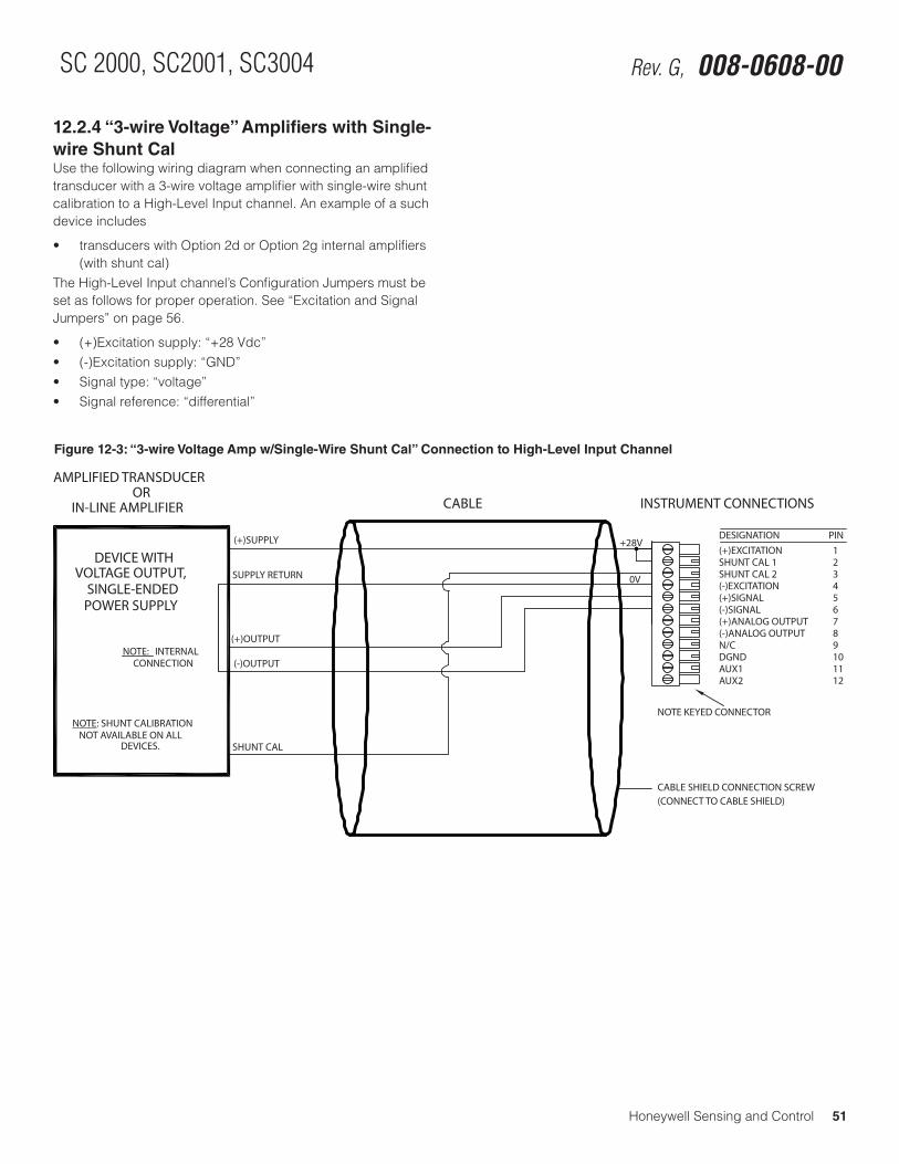
Honeywell Sensing and Control 51
SC 2000, SC2001, SC3004 Rev. G, 008-0608-00
12.2.4 “3-wire Voltage” Amplifiers with Single-wire Shunt CalUse the following wiring diagram when connecting an amplified transducer with a 3-wire voltage amplifier with single-wire shunt calibration to a High-Level Input channel. An example of a such device includes
• transducerswithOption2dorOption2ginternalamplifiers(with shunt cal)
The High-Level Input channel’s Configuration Jumpers must be set as follows for proper operation. See “Excitation and Signal Jumpers” on page 56.
• (+)Excitationsupply:“+28Vdc”• (-)Excitationsupply:“GND”• Signaltype:“voltage”• Signalreference:“differential”
Figure 12-3: “3-wire Voltage Amp w/Single-Wire Shunt Cal” Connection to High-Level Input Channel
123456789101112
(+)EXCITATIONSHUNT CAL 1SHUNT CAL 2(-)EXCITATION(+)SIGNAL(-)SIGNAL(+)ANALOG OUTPUT(-)ANALOG OUTPUTN/CDGNDAUX1AUX2
DESIGNATION PIN
CABLE SHIELD CONNECTION SCREW
(+)SUPPLY
(+)OUTPUT
(-)OUTPUT
IN-LINE AMPLIFIER CABLE INSTRUMENT CONNECTIONS
(CONNECT TO CABLE SHIELD)
ORAMPLIFIED TRANSDUCER
SUPPLY RETURN
SHUNT CAL
NOTE: SHUNT CALIBRATIONNOT AVAILABLE ON ALL
DEVICES.
POWER SUPPLYSINGLE-ENDED
VOLTAGE OUTPUT,DEVICE WITH
NOTE KEYED CONNECTOR
+28V
0V
NOTE: INTERNALCONNECTION
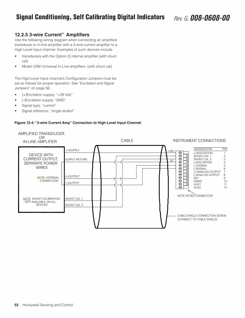
52 Honeywell Sensing and Control
Signal Conditioning, Self Calibrating Digital Indicators Rev. G, 008-0608-00
12.2.5 3-wire Current” AmplifiersUse the following wiring diagram when connecting an amplified transducer or in-line amplifier with a 3-wire current amplifier to a High-Level Input channel. Examples of such devices include
• transducerswiththeOption2jinternalamplifier(withshuntcal)
• ModelU3WUniversalIn-Lineamplifiers(withshuntcal)
The High-Level Input channel’s Configuration Jumpers must be set as follows for proper operation. See “Excitation and Signal Jumpers” on page 56.
• (+)Excitationsupply:“+28Vdc”• (-)Excitationsupply:“GND”• Signaltype:“current”• Signalreference:“singleended”
123456789101112
(+)EXCITATIONSHUNT CAL 1SHUNT CAL 2(-)EXCITATION(+)SIGNAL(-)SIGNAL(+)ANALOG OUTPUT(-)ANALOG OUTPUTN/CDGNDAUX1AUX2
DESIGNATION PIN
CABLE SHIELD CONNECTION SCREW
(+)SUPPLY
SHUNT CAL 1
(+)OUTPUT
(-)OUTPUT
IN-LINE AMPLIFIER CABLE INSTRUMENT CONNECTIONS
(CONNECT TO CABLE SHIELD)
ORAMPLIFIED TRANSDUCER
SUPPLY RETURN
SHUNT CAL 2
NOTE: SHUNT CALIBRATIONNOT AVAILABLE ON ALL
DEVICES.
SEPARATE POWERCURRENT OUTPUT,
DEVICE WITH
NOTE KEYED CONNECTOR
+28V
0V
WIRES
NOTE: INTERNALCONNECTION
Figure 12-4: “3-wire Current Amp” Connection to High-Level Input Channel
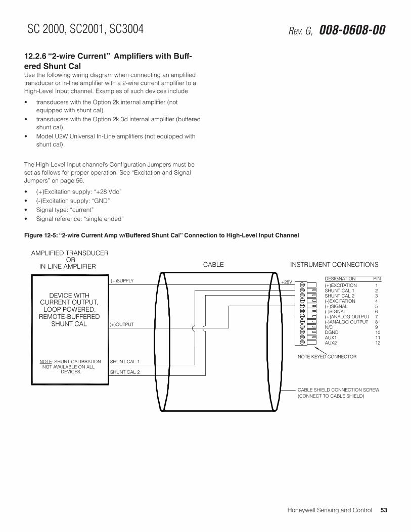
Honeywell Sensing and Control 53
SC 2000, SC2001, SC3004 Rev. G, 008-0608-00
12.2.6 “2-wire Current” Amplifiers with Buff-ered Shunt CalUse the following wiring diagram when connecting an amplified transducer or in-line amplifier with a 2-wire current amplifier to a High-Level Input channel. Examples of such devices include
• transducerswiththeOption2kinternalamplifier(notequipped with shunt cal)
• transducerswiththeOption2k,3dinternalamplifier(bufferedshunt cal)
• ModelU2WUniversalIn-Lineamplifiers(notequippedwithshunt cal)
The High-Level Input channel’s Configuration Jumpers must be set as follows for proper operation. See “Excitation and Signal Jumpers” on page 56.
• (+)Excitationsupply:“+28Vdc”• (-)Excitationsupply:“GND”• Signaltype:“current”• Signalreference:“singleended”
Figure 12-5: “2-wire Current Amp w/Buffered Shunt Cal” Connection to High-Level Input Channel
123456789101112
(+)EXCITATIONSHUNT CAL 1SHUNT CAL 2(-)EXCITATION(+)SIGNAL(-)SIGNAL(+)ANALOG OUTPUT(-)ANALOG OUTPUTN/CDGNDAUX1AUX2
DESIGNATION PIN
CABLE SHIELD CONNECTION SCREW
(+)SUPPLY
SHUNT CAL 1
(+)OUTPUT
IN-LINE AMPLIFIER CABLE INSTRUMENT CONNECTIONS
(CONNECT TO CABLE SHIELD)
ORAMPLIFIED TRANSDUCER
SHUNT CAL 2
NOTE: SHUNT CALIBRATIONNOT AVAILABLE ON ALL
DEVICES.
LOOP POWERED,CURRENT OUTPUT,
DEVICE WITH
NOTE KEYED CONNECTOR
+28V
REMOTE-BUFFEREDSHUNT CAL
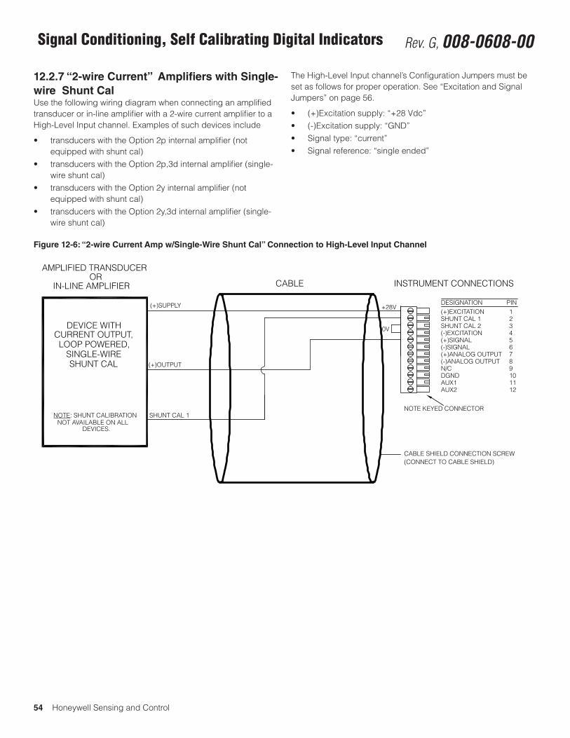
54 Honeywell Sensing and Control
Signal Conditioning, Self Calibrating Digital Indicators Rev. G, 008-0608-00
12.2.7 “2-wire Current” Amplifiers with Single-wire Shunt CalUse the following wiring diagram when connecting an amplified transducer or in-line amplifier with a 2-wire current amplifier to a High-Level Input channel. Examples of such devices include
• transducerswiththeOption2pinternalamplifier(notequipped with shunt cal)
• transducerswiththeOption2p,3dinternalamplifier(single-wire shunt cal)
• transducerswiththeOption2yinternalamplifier(notequipped with shunt cal)
• transducerswiththeOption2y,3dinternalamplifier(single-wire shunt cal)
The High-Level Input channel’s Configuration Jumpers must be set as follows for proper operation. See “Excitation and Signal Jumpers” on page 56.
• (+)Excitationsupply:“+28Vdc”• (-)Excitationsupply:“GND”• Signaltype:“current”• Signalreference:“singleended”
Figure 12-6: “2-wire Current Amp w/Single-Wire Shunt Cal” Connection to High-Level Input Channel
123456789101112
(+)EXCITATIONSHUNT CAL 1SHUNT CAL 2(-)EXCITATION(+)SIGNAL(-)SIGNAL(+)ANALOG OUTPUT(-)ANALOG OUTPUTN/CDGNDAUX1AUX2
DESIGNATION PIN
CABLE SHIELD CONNECTION SCREW
(+)SUPPLY
SHUNT CAL 1
(+)OUTPUT
IN-LINE AMPLIFIER CABLE INSTRUMENT CONNECTIONS
(CONNECT TO CABLE SHIELD)
ORAMPLIFIED TRANSDUCER
NOTE: SHUNT CALIBRATIONNOT AVAILABLE ON ALL
DEVICES.
LOOP POWERED,CURRENT OUTPUT,
DEVICE WITH
NOTE KEYED CONNECTOR
+28V
SINGLE-WIRESHUNT CAL
0V
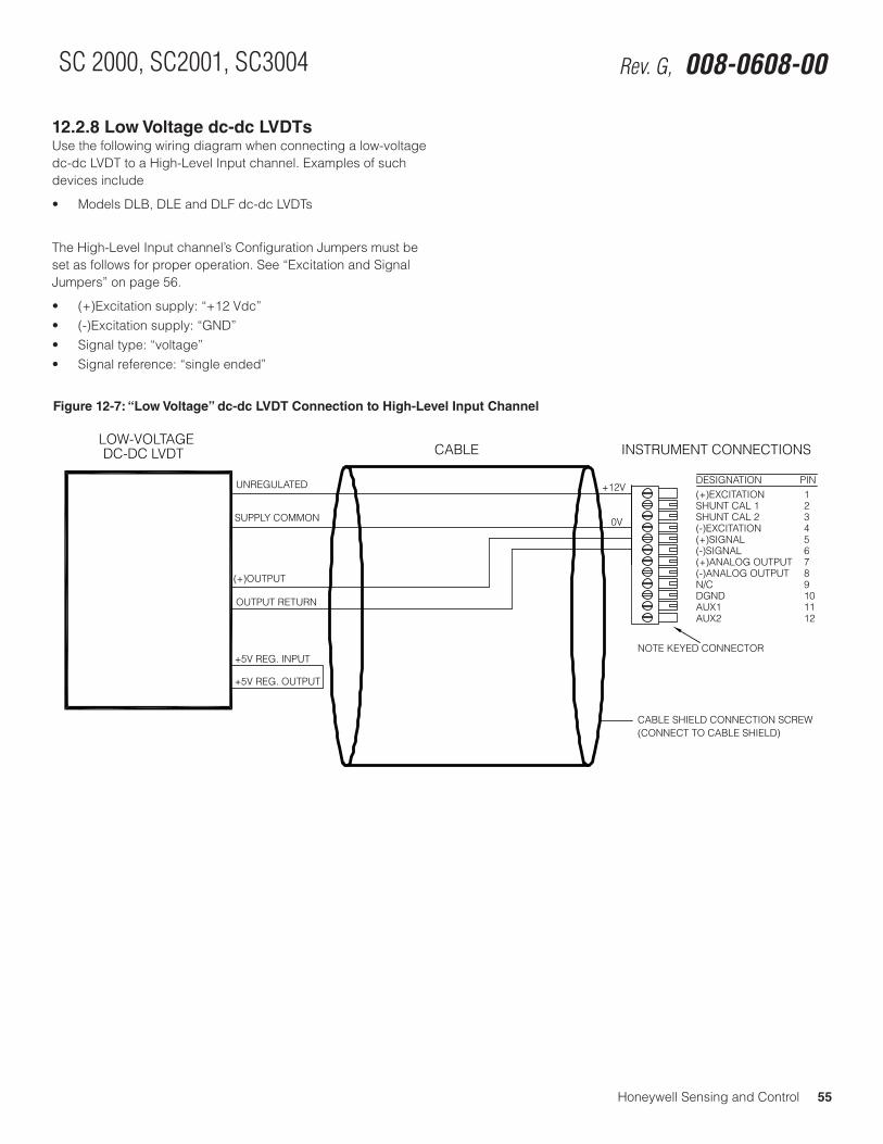
Honeywell Sensing and Control 55
SC 2000, SC2001, SC3004 Rev. G, 008-0608-00
12.2.8 Low Voltage dc-dc LVDTsUse the following wiring diagram when connecting a low-voltage dc-dc LVDT to a High-Level Input channel. Examples of such devices include
• ModelsDLB,DLEandDLFdc-dcLVDTs
The High-Level Input channel’s Configuration Jumpers must be set as follows for proper operation. See “Excitation and Signal Jumpers” on page 56.
• (+)Excitationsupply:“+12Vdc”• (-)Excitationsupply:“GND”• Signaltype:“voltage”• Signalreference:“singleended”
Figure 12-7: “Low Voltage” dc-dc LVDT Connection to High-Level Input Channel
123456789101112
(+)EXCITATIONSHUNT CAL 1SHUNT CAL 2(-)EXCITATION(+)SIGNAL(-)SIGNAL(+)ANALOG OUTPUT(-)ANALOG OUTPUTN/CDGNDAUX1AUX2
DESIGNATION PIN
CABLE SHIELD CONNECTION SCREW
UNREGULATED
+5V REG. INPUT
(+)OUTPUT
OUTPUT RETURN
DC-DC LVDT CABLE INSTRUMENT CONNECTIONS
(CONNECT TO CABLE SHIELD)
LOW-VOLTAGE
SUPPLY COMMON
+5V REG. OUTPUT
NOTE KEYED CONNECTOR
+12V
0V
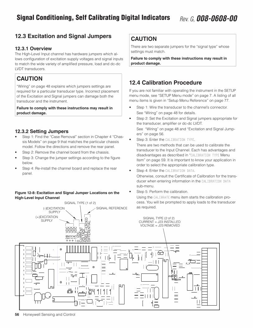
56 Honeywell Sensing and Control
Signal Conditioning, Self Calibrating Digital Indicators Rev. G, 008-0608-00
12.3 Excitation and Signal Jumpers
12.3.1 OverviewThe High-Level Input channel has hardware jumpers which al-lows configuration of excitation supply voltages and signal inputs to match the wide variety of amplified pressure, load and dc-dc LVDT transducers.
CAUTION“Wiring” on page 48 explains which jumpers settings are required for a particular transducer type. Incorrect placement of the Excitation and Signal jumpers can damage both the transducer and the instrument.
Failure to comply with these instructions may result in product damage.
12.3.2 Setting Jumpers• Step1:Findthe“CaseRemoval”sectioninChapter4“Chas-
sis Models” on page 9 that matches the particular chassis model. Follow the directions and remove the rear panel.
• Step2:Removethechannelboardfromthechassis.• Step3:Changethejumpersettingsaccordingtothefigure
below.• Step4:Re-installthechannelboardandreplacetherear
panel.
CAUTIONThere are two separate jumpers for the “signal type” whose settings must match.
Failure to comply with these instructions may result in product damage.
12.4 Calibration ProcedureIf you are not familiar with operating the instrument in the SETUP menu mode, see “SETUP Menu mode” on page 7. A listing of all menu items is given in “Setup Menu Reference” on page 77.
• Step1:Wirethetransducertothechannel’sconnector. See “Wiring” on page 48 for details.• Step2:SettheExcitationandSignaljumpersappropriatefor
the transducer, amplifier or dc-dc LVDT. See “Wiring” on page 48 and “Excitation and Signal Jump-
ers” on page 56.• Step3:EntertheCALIBRATION TYPE. There are two methods that can be used to calibrate the
transducer to the Input Channel. Each has advantages and disadvantages as described in “CALIBRATION TYPE Menu Item” on page 59. It is important to know your application in order to select the appropriate calibration type.
• Step4:EntertheCALIBRATION DATA. Otherwise, consult the Certificate of Calibration for the trans-
ducer when entering information in the CALIBRATION DATA sub-menu.
• Step5:Performthecalibration. Using the CALIBRATE menu item starts the calibration pro-
cess. You will be prompted to apply loads to the transducer as required.
Figure 12-8: Excitation and Signal Jumper Locations on the High-Level Input Channel
(+)EXCITATIONSUPPLY
(-)EXCITATIONSUPPLY
SIGNAL TYPE (1 of 2)
SIGNAL REFERENCE
SIGNAL TYPE (2 of 2)CURRENT = J23 INSTALLEDVOLTAGE = J23 REMOVED
Honeywell Sensing and Control 57
SC 2000, SC2001, SC3004 Rev. G, 008-0608-00
12.5 SpecificationsTRANSDUCER INPUT
Transducer type amplified with voltage or current output, (field selectable)
Excitation voltage1 ±15Vdc@40mAmax.+28 Vdc @ 75 mA max.+12 Vdc @ 40 mA max.(field selectable)
Excitation overcurrent protection
yes
Transducer full-scale output
±1,±5,±10Vdc4 mA to 20 mA (field selectable)
Amplifier gain selection automatic
Calibration type shunt, or 2-, 3- or 5-point known load
Differential Input Volt-age
±55mV(max.)
A/D Converter 24-bit Sigma-Delta
Low-pass filter digital, 24-tap FIR
Resolution and frequen-cy response
see “FREQ. RESPONSE Menu Item” on page 58
INSTRUMENT-ONLY ACCURACY(Sense wires used; frequency response setting <16 Hz; Linearity, repeatability, and hysteresis)
Known-load calibration ±0.01%FS
AUXILLARY INPUTS
Quantity 2
Type momentary contact closure
Response time < 5 ms
Field-selectable func-tions
tare on, tare off, peak/valley clear, peak/valley hold, track hold
ANALOG OUTPUTS
Output voltage range 5,±5,10or±10Vdc(fieldselect-able)
Output current range (optional current output channels)
4 mA to 20 mA
Source any channel’s track, peak, or valley value
Isolation 500 V
Resolution 13 bits
Frequency response same as input when driven by the same channel’s tracking data
1 Total excitation current of all channels must not exceed 120 mA for Models SC2000 or SC2001 and 310 mA for Model SC3004.
12.6 Channel MenuEach High-Level Input channel is configured and calibrated via its channel menu. Detailed instructions on operating the instru-ment in the SETUP Menu mode can be found in “SETUP Menu mode” on page 7. A diagram of all menus is located in “Setup Menu Reference” on page 77.
12.6.1 OPERATION Sub-MenuThis menu controls the operation of this channel when the instru-ment is in the RUN mode.
AUTO-ZERO Menu ItemThis enables or disables the channel’s automatic zeroing func-tion. The auto-zero function can remove the effect of slight tem-perature shifts in the transducer’s output. The two options for this menu item are “ON” and “OFF”.
When enabled, the channel will reset its tracking value to zero when the tracking value has never been more positive than +10 or more negative than -10 display counts for any 10 second period.
For example, assume that the DISPLAY.DECPT menu item is set to 000.00 (two decimal points). If the tracking value never leaves the range of -000.10 to +000.10 for any 10 second period, then tracking value will reset to 000.00 automatically.
NOTICETo compensate for the transducer’s initial warm-up shift, the auto-zero function operates every 2 seconds during the first 60 seconds of RUN mode operation.
58 Honeywell Sensing and Control
Signal Conditioning, Self Calibrating Digital Indicators Rev. G, 008-0608-00
FREQ. RESPONSE Menu ItemThis sets the frequency response, step response, and resolution of the channel according to the table below. The tracking value, peak/valley detector values and analog output on this channel are all affected. The default value of 016. HERTZ is suitable for most applications.
Frequency Response
Step Response (ms) (typical)
Resolution (counts) (not including min. 10% overrange/underrange capability)
5V & 10V Inputs
1V & 4-20mA Inputs
002. HERTZ/FAST
40 ±50000 ±50000
002. HERTZ 440 ±50000 ±50000
008. HERTZ 110 ±25000 ±25000
016. HERTZ 55 ±25000 ±20000
032. HERTZ 28 ±20000 ±10000
050. HERTZ 16 ±15000 ±10000
100. HERTZ 8 ±10000 ±5000
250. HERTZ 3 ±10000 ±5000
500. HERTZ 2 ±4000 ±2500
800. HERTZ 2 ±2500 ±2500
POWER-ON SOURCE Menu ItemThis menu selects which value is displayed by the channel when first entering the RUN mode.
The choices are:
• “TRACK” means the live tracking value of the channel. • “PEAK” means the highest value of the channel.• “VALLEY” means the lowest value of the channel.• “TRACK / PEAK” means the live tracking value and the highest
value of the channel. (Only available on Model SC3004).• “TRACK / VALLEY” means the live tracking value and the low-
est value of the channel. (Only available on Model SC3004).• “PEAK / VALLEY” means the highest and lowest values of the
channel. (Only available on Model SC3004).
12.6.2 DISPLAY SETUP Sub-MenuThis menu controls how data values are displayed by the channel and transmitted via serial communications.
DISPLAY. DIGITS Menu ItemSelects the number of digits displayed by the channel. The choices are:
• “5 DIGIT-BIPOLAR” displays both positive and negative num-berswithfivefulldigits(±99999).
• “6 DIGIT-UNIPLOAR” displays positive numbers with six full digits (999999) and negative numbers with five full digits (-99999).
• “7 DIGIT UNIPOLAR” displays positive number with seven full digits (9999999) and negative numbers with six digits (-999999).
DISPLAY. DECPT Menu ItemSelects the decimal point location on the channel’s display and serial communications output. Use the [UP] and [DOWN] buttons to move the decimal point to the right and left.
This menu item may be automatically updated by a transducer’s Signature Module.
DISPLAY. COUNT-BY Menu ItemDetermines by what value the display increments or decrements. This will make the display less sensitive to a noisy signal. The choices are:
• “00001”
• “00002”
• “00005”
• “00010”
• “00020”
• “00050”
• “00100”
• “00200”
DISPLAY. UNITS Menu ItemSpecifies the four character label that is displayed to the right of the channel’s values.
NOTICEThis menu item doesn’t change the mathematical scaling of the channel’s values; that can be changed by altering the “CALIBRATION DATA -> FULL SCALE VALUE” menu item and then performing a re-calibration.
This menu item doesn’t change the mathematical scaling of the channel’s values; that can be changed by altering the “CALIBRA-TION DATA -> FULL SCALE VALUE” menu item and then performing a re-calibration.
When a character position is flashing press the [UP] or [DOWN] button to change the character. Press [ENTER] to advance to the next character.
Honeywell Sensing and Control 59
SC 2000, SC2001, SC3004 Rev. G, 008-0608-00
DISPLAY. AVERAGE Menu ItemControls the speed with which the channel’s display values will update. Display averaging does not affect the channel’s analog output or its peak/valley detection, which will proceed at the speed selected by the ”OPERATION -> FREQ. RESPONSE” menu item. The choices are:
• “ON”meansthatthedisplaywillupdatefourtimeseachsec-ond. The channel’s values will be averaged for 1/4 second, then displayed.
• “OFF”meansthatthechannel’sdisplaywillupdateasquickly as possible.
12.6.3 AUXn FUNCTION Menu ItemsThe AUX1 FUNCTION and AUX2 FUNCTION menu items determine what happens when the Auxiliary Function pins (labeled as “AUX1” and “AUX2”) on the channel’s connector are activated. These pins are “activated” when connected to the DGND pin. The choices are:
• “DISABLED” means that activating the pin does nothing.• “TRACK HOLD” means that the tracking, peak and valley values
will not be updated.• “HIGH/LOW HOLD” means that the peak and valley values will
not be updated.• “HIGH/LOW CLEAR” means that the peak and valley values are
reset.• “TARE ON” activates the channel’s Tare function (resets it to
zero).• “TARE OFF” deactivates the channel’s Tare function.
As the Auxiliary Function pins are not isolated, it is recommended that a push-button switch or relay is used to connect these pins to the Digital Ground pin.
12.6.4 CALIBRATION TYPE Menu ItemThis chooses the type of calibration technique to be used. There are two methods that can be used to calibrate the transducer to the Input Channel. Each has advantages and disadvantages as described in the table below.
Table 12-2: Comparison of Calibration Types
Sh
un
t C
alib
rati
on
2-, 3
-, o
r 5-
po
int
Kn
ow
n L
oad
Cal
i-b
rati
on
RECOMMENDED...
...for most applications no yes
...when frequently swapping transducers
yes no
...when best possible accu-racy required
no yes
PROs and CONs
Relative accuracy good best
Requires actual, calibrated loads to be applied
no yes
CALIBRATION TECHNIQUE
Zero-scale point from... applied load applied load
Full-scale point from... transducer output when shunt cal pins applied
applied load
Linearity correction from... n/a 2-point: none;3- or 5-point: applied load
60 Honeywell Sensing and Control
Signal Conditioning, Self Calibrating Digital Indicators Rev. G, 008-0608-00
It is important to know your application in order to select the appropriate calibration type. When the best possible accuracy is required, Known-Load Calibration is recommended. However, if known-loads are not available, Shunt Calibration may be used instead.
The choices for this menu item are:
• “TYPE= SHUNT CAL” means Shunt Calibration. First, you are prompted to apply the load entered in the “ZERO SCALE VALUE” register. Next, the instrument interconnects the Shunt Cal 1 and Shunt Cal 2 pins. This activates the transducer’s or in-line amplifier’s shunt calibration circuit which causes a predictable apparent signal. The instrument then takes a reading and adjusts itself using the “SHUNT CAL VALUE” regis-ter.
• “TYPE= 2 POINT CAL” means 2-Point Known Load Calibra-tion. You are prompted to apply the loads to the transducer that were entered in the “KNOWN POINT 1/2” and “KNOWN POINT 2/2” registers. This technique assumes that the transducer is linear, so the usual loads used are zero scale and full scale.
• “TYPE= 3 POINT CAL” means 3-Point Known Load Calibration. You are prompted to apply the loads to the transducer that were entered in the “KNOWN POINT 1/3” and “KNOWN POINT 2/3” and “KNOWN POINT 3/3” registers. This technique can be used to compensate for the non-linearity in the transducer. The usual loads used are zero scale, half scale and full scale, but you are not restricted to these loads.
• “TYPE= 5 POINT CAL” means 5-Point Known Load Calibration. You are prompted to apply the loads to the transducer that were entered in the “KNOWN POINT 1/5”, “KNOWN POINT 2/5”, “KNOWN POINT 3/5”, “KNOWN POINT 4/5” and “KNOWN POINT 5/5” registers. This technique can be used to compensate for the non-linearity in the transducer. The usual loads used are zero scale, one-quarter scale, half scale, three-quarters scale and full scale, but you are not restricted to these loads.
The selection of the calibration type affects what menu items ap-pear in the CALIBRATION DATA sub-menu.
12.6.5 CALIBRATION DATA Sub-MenuThis enters the values that will be used by the instrument when it calibrates itself to the transducer. The menu items that are displayed will change according to what the CALIBRATION TYPE is set for.
FULL SCALE VOLT or FULL SCALE CURR Menu ItemThe nominal transducer/amplifier output when its full-scale load is applied to it, in volts or milliamps. This menu item is used by the instrument to set gain of its amplifier circuit. This value is normally found on the transducer’s Certificate of Calibration or amplifier’s Application Note.
FULL SCALE VALUE Menu ItemThe transducer’s full-scale output in engineering units. It is avail-able only with the Shunt Calibration type.
ZERO SCALE VALUE Menu ItemThe transducer’s zero-scale output in engineering units, which is usually zero. It is available only with the Shunt Calibration type.
SHUNT CAL VALUE Menu ItemThe shunt calibration value must be calculated by using informa-tion found on the transducer’s Certificate of Calibration and the following formula:
SHUNT CAL VALUE = Shunt-calibration output
Full-scale outputx Full-scale capacity
The terms have the following meanings:
• Shunt-CalibrationOutput:Thetransducer’soutputwhenitsshunt calibration function is activated in Volts or milliamps. Sometimes called “Shunt Cal. Factor”.
• Full-ScaleOutput:Thetransducer’sfull-scaleoutputinVoltsor milliamps. Sometimes called “Calibration Factor”.
• Full-ScaleCapacity:Thetransducer’sdesiredfull-scaleread-ing in engineering units (PSI, lbs, Kg, etc.). You may wish to convert the engineering units of this value. For example, if the transducer full scale is 3000 PSIG and you wish the channel to read in bar, you must convert 3000 PSIG into 206.84 bar.
This menu item is only available with the Shunt Calibration type.
To verify proper transducer/amplifier operation, you can activate the transducer’s/amplifier’s shunt calibration function while the instrument is in the RUN mode. Press and hold the [ENTER] but-ton for three seconds; this will activate the transducer’s/amplifier’s shunt calibration function and display the reading.
Honeywell Sensing and Control 61
SC 2000, SC2001, SC3004 Rev. G, 008-0608-00
KNOWN POINT x/y Menu ItemsThis enters the engineering units for the known-load calibration points. These points must match the actual loads that you will apply to the instrument during calibration. The number of calibra-tions points depends on the CALIBRATION TYPE.
When using the 2-Point Known Load Calibration type, the follow-ing menu items are available:
• “KNOWN POINT 1/2”: point 1 of 2, usually 0% of the transduc-er’s full-scale capacity.
• “KNOWN POINT 2/2”: point 2 of 2, usually 100% of the trans-ducer’s full-scale capacity.
When using the 3-Point Known Load Calibration type, the follow-ing menu items are available:
• “KNOWN POINT 1/3”: point 1 of 3, usually 0% of the transduc-er’s full-scale capacity.
• “KNOWN POINT 2/3”: point 2 of 3, usually 50% of the transduc-er’s full-scale capacity.
• “KNOWN POINT 3/3”: point 3 of 3, usually 100% of the trans-ducer’s full-scale capacity.
When using the 5-Point Known Load Calibration type, the follow-ing menu items are available:
• “KNOWN POINT 1/5”: point 1 of 5, usually 0% of the transduc-er’s full-scale capacity.
• “KNOWN POINT 2/5”: point 2 of 5, usually 25% of the transduc-er’s full-scale capacity.
• “KNOWN POINT 3/5”: point 3 of 5, usually 50% of the transduc-er’s full-scale capacity.
• “KNOWN POINT 4/5”: point 4 of 5, usually 75% of the transduc-er’s full-scale capacity.
• “KNOWN POINT 5/5”: point 5 of 5, usually 100% of the trans-ducer’s full-scale capacity.
NOTICETo insure both correct operation of the transducer and ap-plication of the load, the instrument expects the voltage or current applied at each known-load point to be increasing. For example, the load applied at Known-Load Point 2/2 must cause the transducer to produce a more positive voltage or current than at Known-Load Point 1/2.
These menu items are only available with the Known-Load Cali-bration types.
12.6.6 CALIBRATE Menu ItemThis menu item performs a calibration according to what was en-tered in the CALIBRATION TYPE and CALIBRATION DATA menu items.
NOTICEBefore performing a calibration,
• thetransducermustbeconnectedtotheinstrument,• thechannel’sExcitationandSignalJumpersmustbeset,• theCALIBRATION TYPE must be selected (see “CALIBRATION
TYPE Menu Item” on page 59), and • theCALIBRATION DATA must be entered (see “CALIBRATION
DATA Sub-Menu” on page 60).
NOTICEFor maximum accuracy, allow at least twenty minutes of warm-up with the excitation voltage applied to the transducer before calibration.
If the CALIBRATION TYPE is Shunt Calibration...• ThedisplaywillreadDOING SHUNT CAL, and prompt you to
APPLY 00000 UNIT (where 00000 and UNIT are previously entered as ZERO SCALE VALUE and DISPLAY. UNITS. When you have applied this load to the transducer, press [ENTER].
• ThedisplaywillthenreadWORKING and calibration will take place. Upon completion, the display will indicate DONE and the instrument will return to the RUN mode.
If the CALIBRATION TYPE is 2-Point Known Load Calibration...• ThedisplaywillreadDOING 2POINT CAL, and prompt you to
APPLY 00000 UNIT (where 00000 and UNIT are previously entered as KNOWN POINT 1/2 and DISPLAY. UNITS). When you have applied this load to the transducer, press [ENTER].
• ThedisplaywillreadWORKING, then APPLY 01000 UNIT (where 01000 and UNIT are previously entered as KNOWN POINT 2/2 and DISPLAY. UNITS). When you have applied this load to the transducer, press [ENTER].
• Uponcompletion,thedisplaywillindicateDONE and the instrument will return to the RUN mode.
62 Honeywell Sensing and Control
Signal Conditioning, Self Calibrating Digital Indicators Rev. G, 008-0608-00
If the CALIBRATION TYPE is 3-Point Known Load Calibration...• ThedisplaywillreadDOING 3POINT CAL, and prompt you to
APPLY 00000 UNIT (where 00000 and UNIT are previously entered as KNOWN POINT 1/3 and DISPLAY. UNITS). When you have applied this load to the transducer, press [ENTER].
• ThedisplaywillreadWORKING, then APPLY 00500 UNIT (where 00500 and UNIT are previously entered as KNOWN POINT 2/3 and DISPLAY. UNITS). When you have applied this load to the transducer, press [ENTER].
• ThedisplaywillreadWORKING, then APPLY 01000 UNIT (where 01000 and UNIT are previously entered as KNOWN POINT 3/3 and DISPLAY. UNITS). When you have applied this load to the transducer, press [ENTER].
• Uponcompletion,thedisplaywillindicate DONE and the instrument will return to the RUN mode.
If the CALIBRATION TYPE is 5-Point Known Load Calibration...• ThedisplaywillreadDOING 5POINT CAL, and prompt you to
APPLY 00000 UNIT (where 00000 and UNIT are previously entered as KNOWN POINT 1/5 and DISPLAY. UNITS). When you have applied this load to the transducer, press [ENTER].
• ThedisplaywillreadWORKING, then APPLY 00250 UNIT (where 00250 and UNIT are previously entered as KNOWN POINT 2/5 and DISPLAY. UNITS). When you have applied this load to the transducer, press [ENTER].
• ThedisplaywillreadWORKING, then APPLY 00500 UNIT (where 00500 and UNIT are previously entered as KNOWN POINT 3/5 and DISPLAY. UNITS). When you have applied this load to the transducer, press [ENTER].
• Thedisplaywillread WORKING, then APPLY 00750 UNIT (where 00750 and UNIT are previously entered as KNOWN POINT 4/5 and DISPLAY. UNITS). When you have applied this load to the transducer, press [ENTER].
• ThedisplaywillreadWORKING, then APPLY 01000 UNIT (where 01000 and UNIT are previously entered as KNOWN POINT 5/5 and DISPLAY. UNITS). When you have applied this load to the transducer, press [ENTER].
• ThedisplaywillnowreadRETURN PNTS.=NO. If you press [ENTER], the display will indicate DONE and the instrument will return to the RUN mode. If you use the [UP] button and [ENTER] to select RETURN POINTS=YES, you may now apply the same loads again but in reverse order. This will allow the instrument to measure and partially eliminate any hysteresis that may be present in the transducer. After the loads have been applied again, the display will indicate DONE and the instrument will return to the RUN mode.
12.6.7 DAC SETUP Sub-MenuThis sub-menu contains four items that control the Digital-to-Ana-log Converter (DAC) output of the channel.
DAC. CHANNEL Menu ItemThis chooses which channel will drive the DAC output. Normally, the DAC located on a particular channel will be driven by that channel, but that need not be the case. For example, if several channels were assigned to load cells on a weighing platform, the sum of all channels could (mathematically) drive one channel’s DAC output.
If the DAC is set-up to be driven by its own channel’s tracking value, the Analog Output will have the frequency response speci-fied by the channel’s FREQ. RESPONSE menu item. Otherwise, the Analog Output will operate more slowly.
DAC. SOURCE Menu ItemThis designates the data source of the channel monitored by the analog output.
The options for this menu item are:
• “TRACK” means the live tracking value of the channel. • “PEAK” means the highest value of the channel since the
peak/valley detector was last cleared.• “VALLEY” means the lowest value of the channel since the
peak/valley detector was last cleared.
If the DAC is set-up to be driven by its own channel’s tracking value, the Analog Output will have the frequency response speci-fied by the channel’s FREQ. RESPONSE menu item. Otherwise, the Analog Output will operate more slowly.
DAC. ZERO-SCALE Menu ItemThis specifies what value, in engineering units, corresponds to zero output on the Analog Output.
“Zero output” might be 0 Volts, 2.5 Volts, 5 Volts, 4 mA or 12 mA depending on if the channel has a voltage or current output and how it is configured. See “Analog Output Configuration” on page 68 for details.
DAC. FULL-SCALE Menu ItemSpecifies what value, in engineering units, corresponds to full output on the Analog Output.
“Full output” might be 5 Volts, 10 Volts or 20 mA depending on if the channel has a voltage or current output and how it is config-ured. See “Analog Output Configuration” on page 68 for details.
Honeywell Sensing and Control 63
SC 2000, SC2001, SC3004 Rev. G, 008-0608-00
12.6.8 DIAGNOSTICS Sub-Menu DAC FULL SCALE Menu ItemWhen this menu item is selected, the Analog Output of the channel is forced to its full-scale output, then DAC UPDATED is displayed. This is useful when calibrating or trimming the readout connected to the Analog Output.
DAC ZERO SCALE Menu ItemWhen this menu item is selected, the Analog Output of the channel is forced to its zero-scale output, then DAC UPDATED is displayed. This is useful when calibrating or trimming the readout connected to the Analog Output.
VERSION INFO Menu ItemThis menu item displays the part number and revision level of the firmware used by this channels microprocessor.
DISPLAY ADC Menu ItemThe options for this menu item are:
• “OFF” will allow the [VALUE] button to cycle through “TK” (tracking value), “HI” (peak value) and “LO” (valley value). This is the recommended option.
• “ON” will allow the “AD” (percentage of the Analog-to-Digital converter’s full-scale digitizing capability) display source to be available along with “TK” (tracking value), “HI” (peak value) and “LO” (valley value) when the [VALUE] button is pressed on the front panel.
The Analog-to-Digital converter counts are displayed as a per-centage from -100.00% to 100.00%.
This can be used to verify that the transducer’s output does not exceed the input range of the instrument. If the Analog-to-Digital converterreadingsdisplaymorethan±10%whenthereisnoload on the transducer, the transducer has a high zero offset.
LINEARIZATION Menu ItemThe options for this menu item are:
• “ON” will allow linearization data obtained from either the Sig-nature Module or a 3-Point or 5-Point Known Load Calibra-tion to affect a channel’s scaled values. This is the recom-mended option.
• “OFF” will not allow linearization data to effect the channel’s scaled values. This is useful when diagnosing problems in a calibration procedure.
DISABLE CHANNEL Menu ItemThe options for this menu item are:
• “ON” will bypass the INITIALIZE and RUN modes of the chan-nel. The track, peak and valley values of the channel are forced to 0.
• “OFF” will allow normal operation of the channel.
12.7 Analog Output Configuration
12.7.1 Identifying the Output TypeA High-Level Input channel is available with one of two types of digital-to-analog (DAC) outputs: voltage or current. You can de-termine which type of output a channel has by one of three ways:
• Consultingtheinstrument’sCustomerInformationSheet• ExaminingtheSYSTEM MENU -> CONFIGURATION -> CHANNEL nn
TYPE menu item where nn is the number of the channel. If the channel’s type is HIGH-LEVEL V, it has a voltage output. If the channel’s type is HIGH-LEVEL I, it has a current output.
• Examiningthechannel’scircuitboardasshowninthefigurebelow.
12.7.2 Channel Menu ItemsThe Analog Output can be driven by any channel’s track, peak or valley value.
See the “Channel Menu” section earlier in this chapter for a com-plete listing of SETUP menu items available on the DAC. SETUP sub-menu.
12.7.3 Output SelectionJumpers located on the channel’s circuit board determine what outputs are generated when the value selected to drive the Ana-log Output (from the DAC. CHANNEL and DAC. SOURCE menu items) equals the DAC. FULL SCALE and DAC. ZERO SCALE settings.
DAC. ZERO SCALE Output
DAC. FULL SCALE Output
J30 jumper
J31 jumper
CHANNELS WITH VOLTAGE OUTPUT
0 V to 5 V 2.5 Volts 5 Volts open closed
±5V 0 Volts 5 Volts open open
0 V to10 V 5 Volts 10 Volts closed closed
±10V 0 Volts 10 Volts closed open
CHANNELS WITH CURRENT OUTPUT
4 mA to 20 mA 4 mA 20 mA open open
4 mA to 20 mA 12 mA 20 mA open closed
64 Honeywell Sensing and Control
Signal Conditioning, Self Calibrating Digital Indicators Rev. G, 008-0608-00
12.8 Troubleshooting
12.8.1 Error MessagesSee “Error Messages” on page 73 for information relating to error messages.
12.8.2. Common Problems and SolutionsErratic DisplayCheck electrical connections for continuity and the transducer’s and/or amplifier’s wiring code from its Certificate of Calibration and Application Note.
Incorrect wiring may have shorted the excitation power supply. Use the correct wiring diagram to connect the transducer or amplifier to the instrument.
Make sure that the load on the transducer is constant.
Check input voltage or current to the (+)Signal (“+SIG”) and (-)Signal (“-SIG”) pins with a multi-meter.
Blank DisplayIncorrectwiringmayhaveshortedthe±15Vdcexcitationpowersupply. Use the correct wiring diagram to connect the transducer or amplifier to the instrument.
+OVLD or -OVLD on DisplayIndicates that the voltage across the (+)Signal (“+SIG”) and (-)Signal (“-SIG”) pins is overranging or underranging the amplifier circuit. Make certain all wires are connected properly.
If you remove all load from the transducer and you still see this message, the (+)Excitation (“+EXC”) or (-)Excitation (“-EXC”) pins may be shorted to the (+)Signal (“+SIG”) or (-)Signal (“-SIG”) pins.
If you remove all load from the transducer and you get a numeric reading, the transducer may have a high zero offset. Use the
Figure 12-9: Digital-to-Analog Output Jumper Locations
channel’s SETUP menu and set DIAGNOSTICS -> DISPLAY ADC to “ON”; in the RUN mode this will allow the [VALUE] button to dis-play raw A/D readings as a percentage of its full-scale. If the raw A/D readings display more than +/-10% when there is no load on the transducer, the transducer has a high zero offset.
Analog Output IncorrectMake certain of the type of Analog Output (voltage or current) that the channel is equipped with; see “Identifying the Output Type” on page 63.
Use the DIAGNOSTICS -> DAC FULL SCALE and DIAGNOSTICS -> DAC ZERO SCALE menu items to force the Analog Output to a known output. Then, adjust your readout device, panel meter, PLC or data acquisition system to match.
Check the output selection jumpers; see “Output Selection” on page 63.
Auxiliary Function Pins Not OperatingMake sure that the AUX1 FUNCTION or AUX2 FUNCTION SETUP menu items are set correctly; if they are set to DISABLED then they will not operate.
The Auxiliary Function (“AUX1” and “AUX2”) pins must be con-nected to pin 10, not pin 8, to activate them.
Sensitivity to EMI/RFITo obtain maximum immunity to electromagnetic or radio frequen-cy interference, make certain that the shields of the transducer cables are connected to the “cable shield connection screw” on the rear panel of the instrument. See “Wiring” on page 48, “External Arrangement of AC powered SC2000” on page 10 and “External Arrangement of Model SC3004” on page 15.
Honeywell Sensing and Control 65
SC 2000, SC2001, SC3004 Rev. G, 008-0608-00
Chapter 13 Relay Output Channel
13.1 Features
13.1.1 First Channel InstalledThe first Relay Output channel installed in an instrument supple-ments the standard four limits (Limit 1, Limit 2, Limit 3 and Limit 4) . Its four, dry contact relay outputs will mirror the Limit Outputs pins of the System connector.
In the SYSTEM -> CONFIGURATION sub-menu, channels of this type are identified as LIMIT 01-04.
13.1.2 Second Channel InstalledThe second Relay Output channel installed in an instrument adds another four limits to the instrument (Limit 5, Limit 6, Limit 7 and Limit 8). Its relay outputs show the status of these limits.
In the SYSTEM -> CONFIGURATION sub-menu, channels of this type are identified as LIMIT 05-08.
13.1.3 Third Channel InstalledThe third Relay Output channel installed in an instrument adds another four limits to the instrument (Limit 9, Limit 10, Limit 11 and Limit 12). Its relay outputs show the status of these limits.
In the SYSTEM -> CONFIGURATION sub-menu, channels of this type are identified as LIMIT 09-12.
13.1.4 Fourth Channel InstalledThe fourth Relay Output channel installed in an instrument adds another four limits to the instrument (Limit 13, Limit 14, Limit 15 and Limit 16). Its relay outputs show the status of these limits.
In the SYSTEM -> CONFIGURATION sub-menu, channels of this type are identified as LIMIT 13-16.
13.2 WiringThe pin-out for the Relay Output channel’s 12-pin connector is shown in the following table.
Table 13-1 Relay Output Channel Pin Connections
Pin Label Function Ref. Pin
1 (top) RELAY1 NC Relay 1 normally closed 2
2 RELAY1 C Relay 1 common -
3 RELAY1 NO Relay 1 normally open 2
4 RELAY2 NC Relay 2 normally closed 5
5 RELAY2 C Relay 2 common -
6 RELAY2 NO Relay 2 normally open 5
7 RELAY3 NC Relay 3 normally closed 8
8 RELAY3 C Relay 3 common -
9 RELAY3 NO Relay 3 normally open 8
10 RELAY4 NC Relay 4 normally closed 11
11 RELAY4 C Relay 4 common -
12 (bottom)
RELAY4 NO Relay 4 normally open 11
13.3 Setup ProcedureIf you are not familiar with operating the instrument in the SETUP menu mode, see “SETUP Menu mode” on page 7. A listing of all menu item is given in “Setup Menu Reference” on page 77.
• Step1:Wiretothechannel’sconnector. See the “Wiring” section earlier in this chapter for details.• Step2:UsetheappropriateLimitMenutosetupthelimits. See “Limits” on page 24 for information about limits.
NOTICEA SensoCode program running on a Mathematics Virtual Channel may override the default behavior of the relay out-puts. Consult the Customer Information Sheet included with your instrument for details.
13.4 SpecificationsRELAY OUTPUT
Quantity and Type 4 form C
Contact rating 0.5 A @ 50 Vac max. (consult factory for 125 Vac max. operation) 1 A @ 30 Vdc max.
66 Honeywell Sensing and Control
Signal Conditioning, Self Calibrating Digital Indicators Rev. G, 008-0608-00
13.5 Channel MenuThe Relay Output channel’s SETUP menu allows you to manually turn the relays on and off to verify that they are functioning. To change the operation of the limits, see “Limit Menus” on page 55.
Detailed instructions on operating the instrument in the SETUP Menu mode can be found in “SETUP Menu mode” on page 7. A diagram of all menus is located in “Setup Menu Reference” on page 77.
13.5.1 DIAGNOSTICS Sub-Menu
RELAY 1 Menu ItemThe options for this menu item are:• “ON” will turn the relay on.• “OFF” will turn the relay off.
RELAY 2 Menu ItemThe options for this menu item are:• “ON” will turn the relay on.• “OFF” will turn the relay off.
RELAY 3 Menu ItemThe options for this menu item are:• “ON” will turn the relay on.• “OFF” will turn the relay off.
RELAY 4 Menu ItemThe options for this menu item are:• “ON” will turn the relay on.• “OFF” will turn the relay off.
Chapter 14 DAC Output Channel
14.1 FeaturesThe DAC Output channel uses a digital-to-analog converter to generate a voltage or current from any channel’s track, peak or valley value. This type of channel is often used to provide a Math-ematics Virtual channel with an analog output.
14.2 WiringConnect your readout instrument to a DAC Output channel by wiring it to the 12-pin connector of that channel. The Customer In-formation Sheet that shipped with the instrument describes which cards are installed in each channel. The pin-out for this connector is shown on the following table.
Table 14-1: DAC Output Channel Pin Connections
Pin Label Function Ref. Pin
1 (top) N/C No connection
2 N/C No connection
3 N/C No connection
4 N/C No connection
5 N/C No connection
6 N/C No connection
7 +OUT Analog Output 8
8 -OUT Analog Return -
9 N/C No connection
0 N/C No connection
11 N/C No connection
12 (bottom)
N/C No connection
The Analog Output and Analog Return pins are electrically iso-lated from all other pins on the instrument.
Honeywell Sensing and Control 67
SC 2000, SC2001, SC3004 Rev. G, 008-0608-00
14.3 Setup ProcedureIf you are not familiar with operating the instrument in the SETUP menu mode, see “SETUP Menu mode” on page 7. A listing of all menu items is given in “Setup Menu Reference” on page 77.
• Step1:DetermineifyouhaveaVoltageDACOutputchannelor a Current DAC Output channel.
Check the instrument’s Customer Information Sheet, or see “Identifying the Output Type” on page 68.
• Step2:Wirethereadoutinstrumenttothechannel’sconnec-tor.
See the “Wiring” section earlier in this chapter for details.• Step3:Selectthevalue(channelandsource)usedtodrive
the Analog Output See the “Channel Menu” on page 67 for details.• Step4:Selectthefull-scaleandzero-scalesettingsusedto
drive the Analog Output. See the “Channel Menu” on page 67 for details.
14.4 SpecificationsANALOG OUTPUT
Voltage range (voltage output channels)
5Vdc,±5Vdc,or10Vdc
Current range (current output channels)
4 mA to 20 mA
Source any channel’s track, peak or valley value
Isolation 500 V
Resolution 12 bits
Update Rate depends on how many channels are installed in the instrument
14.5 Channel MenuEach DAC Output channel is configured and calibrated via its channel menu. Detailed instructions on operating the instrument in the SETUP Menu mode can be found in “SETUP Menu mode” on page 7. A diagram of all menus is located in “Setup Menu Reference” on page 77.
14.5.1 DAC SETUP Sub-MenuThis sub-menu contains four items that controls the analog output of the channel.
DAC. CHANNEL Menu ItemThis chooses which channel will drive the Digital-to-Analog Con-verter (DAC) output.
DAC. SOURCE Menu ItemThis designates the data source of the channel monitored by the analog output. Each channel has three data sources: the live tracking value (TRACK), its highest value (PEAK), and its lowest value (VALLEY).
The options for this menu item are:
• “TRACK” means the live tracking value of the channel. • “PEAK” means the highest value of the channel since the
peak/valley detector was last cleared.• “VALLEY” means the lowest value of the channel since the
peak/valley detector was last cleared.
DAC. ZERO-SCALE Menu ItemThis specifies what value, in engineering units, corresponds to zero output on the Analog Output.
“Zero output” might be 0 Volts, 2.5 Volts, 5 Volts, 4 mA or 12 mA depending on if the channel has a voltage or current output and how it is configured. See the “Digital-to-Analog Output” section of this chapter for details.
This menu item is not automatically updated by another channel’s Signature Module equipped transducer.
DAC. FULL-SCALE Menu ItemThis specifies what value, in engineering units, corresponds to full output on the Analog Output.
“Full output” might be 5 Volts, 10 Volts or 20 mA depending on if the channel has a voltage or current output and how it is config-ured. See the “Digital-to-Analog Output” section of this chapter for details.
This menu item is not automatically updated by another chan-nel’s Signature Module equipped transducer.
68 Honeywell Sensing and Control
Signal Conditioning, Self Calibrating Digital Indicators Rev. G, 008-0608-00
14.5.2 DIAGNOSTICS Sub-Menu
DAC FULL SCALE Menu ItemWhen this menu item is selected, the Analog Output of the chan-nel is forced to its full-scale output, then DAC UPDATED is displayed. This is useful when calibrating or trimming the readout connected to the Analog Output.
AC ZERO SCALE Menu ItemWhen this menu item is selected, the Analog Output of the channel is forced to its zero-scale output, then DAC UPDATED is displayed. This is useful when calibrating or trimming the readout connected to the Analog Output.
14.6 Analog Output Configuration
14.6.1 Identifying the Output TypeA DAC Output channel is available with one of two types of digital-to-analog (DAC) outputs: voltage or current. You can de-termine which type of output a channel has by one of three ways:
• Consultingtheinstrument’sCustomerInformationSheet• ExaminingtheSYSTEM MENU -> CONFIGURATION -> CHANNEL nn
TYPE menu item where nn is the number of the channel. If the channel’s type is VOLTAGE DAC, it has a voltage output. If the channel’s type is CURRENT DAC, it has a current output.
• Examiningthechannel’scircuitboardasshowninthefigurebelow.
14.6.2 Channel Menu ItemsThe Analog Output can be driven by any channel’s track, peak or valley value.
See the “Channel Menu” section earlier in this chapter for a com-plete listing of SETUP menu items available on the DAC. SETUP sub-menu.
14.6.3 Output SelectionJumpers located on the channel’s circuit board determine what outputs are generated when the value selected to drive the Ana-log Output (from the DAC. CHANNEL and DAC. SOURCE menu items) equals the DAC. FULL SCALE and DAC. ZERO SCALE settings.
DAC. ZERO SCALE Output
DAC. FULL SCALE Output
P31 jumper
J11 jumper
CHANNELS WITH VOLTAGE OUTPUT
0 V to 5 V 2.5 Volts 5 Volts bottom open
±5V 0 Volts 5 Volts bottom closed
5 V 0 Volts 5 Volts top open
0 V to10 V 5 Volts 10 Volts middle open
±10V 0 Volts 10 Volts middle closed
CHANNELS WITH CURRENT OUTPUT
4 mA to 20 mA 4 mA 20 mA bottom closed
4 mA to 20 mA 12 mA 20 mA bottom open
Figure 14-1: Digital-to-Analog Output Jumper Locations
Honeywell Sensing and Control 69
SC 2000, SC2001, SC3004 Rev. G, 008-0608-00
14.7 Troubleshooting
14.7.1 Error MessagesSee “Error Messages” on page 73 for information relating to error messages.
14.7.2 Common Problems and Solutions Analog Output IncorrectMake certain of the type of Analog Output (voltage or current) that the channel is equipped with; see “Identifying the Output Type” on page 68.
Use the DIAGNOSTICS -> DAC FULL SCALE and DIAGNOSTICS -> DAC ZERO SCALE menu items to force the Analog Output to a known output. Then, adjust your readout device, panel meter, PLC or data acquisition system to match.
Check the output selection jumpers; see “Output Selection” on page 68.
Check the “DAC SETUP -> DAC. ZERO-SCALE” and “DAC SETUP -> DAC FULL-SCALE” menu items.
Sensitivity to EMI/RFITo obtain maximum immunity to electromagnetic or radio fre-quency interference, make certain that the shield of the cable is connected to ground/earth only at the readout device. The shield of the cable should not be connected to the instrument.
70 Honeywell Sensing and Control
Signal Conditioning, Self Calibrating Digital Indicators Rev. G, 008-0608-00
Chapter 15 Split Display Virtual Channel
15.1 FeaturesThe Split Display Virtual Channel allows the display of two track, peak or valley values from any two channels at the same time. One value is displayed on the left side of the display, and another value is displayed on the right side.
The display setup used to format each value is inherited from the source channel of the value.
Split Displays are most useful on chassis with a 16-character display such as the Models SC2000 and SC2001. The quad-line, 20-character display of the Model SC3004, however, already allows an Input Channel to show its own Track & Peak, Track & Valley or Peak & Valley values on the display at the same time. Thus, a Split Display Virtual Channel is not generally used on an Model SC3004.
15.2 WiringA Virtual Channel exists in software only; it does not occupy a physical slot inside of the instrument’s chassis. However, a Virtual Channel does require a channel number.
There is no rear-panel connector for a Virtual Channel.
15.3 Setup ProcedureIf you are not familiar with operating the instrument in the SETUP menu mode, see “SETUP Menu mode” on page 7. A listing of all menu item is given in “Setup Menu Reference” on page 77.
• Step1:EnterthevaluetobedisplayedontheleftsidewithLEFT CHANNEL and LEFT SOURCE.
• Step2:EnterthevaluetobedisplayedontherightsidewithRIGHT CHANNEL and RIGHT SOURCE.
15.4 Channel MenuDetailed instructions on operating the instrument in the SETUP Menu mode can be found in “SETUP Menu mode” on page 7. A diagram of all menus is located in “Setup Menu Reference” on page 77.
LEFT CHANNEL Menu ItemThis specifies the channel that is displayed on the left half of the split display.
LEFT SOURCE Menu ItemThis lets you designate the data source of the channel moni-tored by the left half of the split display. Each channel has three data sources: the live tracking value (TRACK), its highest value (PEAK), and its lowest value (VALLEY).
The options for this menu item are:• “TRACK” means the live tracking value of the channel. • “PEAK” means the highest value of the channel since the
peak detector was last cleared.• “VALLEY” means the lowest value of the channel since the
valley detector was last cleared.
RIGHT CHANNEL Menu ItemThis specifies the channel that is displayed on the right half of the split display.
RIGHT SOURCE Menu ItemThis lets you designate the data source of the channel monitored by the right half of the split display. Each channel has three data sources: the live tracking value (TRACK), its highest value (PEAK), and its lowest value (VALLEY).
The options for this menu item are:• “TRACK” means the live tracking value of the channel. • “PEAK” means the highest value of the channel since the
peak detector was last cleared.• “VALLEY” means the lowest value of the channel since the val-
ley detector was last cleared.
LEAVE MENU Menu ItemWhen the menu item is displayed, press [ENTER] to leave this menu. Press [EXIT] to return to the RUN mode.
15.5 TroubleshootingFront Panel Buttons not Operating in RUN ModeWhen a Split Display Virtual channel is displayed the [VALUE], [CLEAR] and [TARE] buttons have no effect. To change one of the values shown on a Split Display Virtual channel, use the its SETUP menu. To clear peak/valley values or tare an Input chan-nel, use the [CHANNEL] button to select an Input channel and then use the [CLEAR] or [TARE] buttons.
Honeywell Sensing and Control 71
SC 2000, SC2001, SC3004 Rev. G, 008-0608-00
Chapter 16 Mathematics Virtual Channel
16.1 FeaturesThe Mathematics Virtual Channel is a powerful, flexible means to allow SC Series Instruments to perform simple to moderate func-tions that previously required the use of expensive programmable logic controllers (PLC).
A Mathematics Virtual Channel is akin to a PLC; it can execute programs written in an interpretive language called SensoCode. At the time of order, your specific application is analyzed by our sales and engineering staff and one or more SensoCode pro-grams are created. These SensoCode programs are loaded into the Mathematics Virtual channels of the instrument at the factory. The end result is an instrument that meets your specific needs but is built with “off-the-shelf” hardware and software.
SensoCode programs allow the instrument to perform a variety of functions including:
• Mathematics: addition, subtraction, multiplication, division, square roots, etc.
• Logical: if/then condition statements, comparison of values• Timing
• Input: from any channel’s track, peak or valley values, open-collector inputs, constant user-entered values from the SETUP menu
• Output: Each Mathematics Channel generates its own track, peak, and valley values. A SensoCode program can “take control” of the Limit Output and/or front panel indicator lights.
16.2 WiringA Virtual Channel exists in software only; it does not occupy a physical slot inside of the instrument’s chassis. However, a Virtual Channel does require a channel number.
A SensoCode program that is executed by a Mathematics Virtual Channel can use the System connector’s Limit Output pins and Function Input pins for its own purposes. Consult the Customer Information Sheet and Supplemental Instructions included with the particular instrument for details.
16.3 Setup ProcedureIf you are not familiar with operating the instrument in the SETUP menu mode, see “SETUP Menu mode” on page 7. A listing of all menu item is given in “Setup Menu Reference” on page 77.
• Step1:ExaminetheSupplementalInstructions. Supplemental Instructions contain important information
about what each Mathematics Channel does and what Func-tion Inputs and/or Limit Output pins of the System connector are used.
• Step2:WiretothepinsontheSystemconnector. See “System Connector” on page 17. It is important to read
the Supplemental Instructions to determine the wiring for your application.
• Step3:Verifyoperation.
16.4 Channel MenuEach Mathematics Virtual Channel can have its configuration and SensoCode programming examined via its channel menu. It is not possible to alter the SensoCode program with the SETUP menu. Detailed instructions on operating the instrument in the SETUP Menu mode can be found in “SETUP Menu mode” on page 7. A diagram of all menus is located in “Setup Menu Refer-ence” on page 77.
16.4.1 SENSOCODE P/N Menu ItemThis menu item displays the part number and revision level of the SensoCode program loaded in this Mathematics Virtual Channel.
16.4.2 USER VALUES Sub-MenuThis sub-menu contains menu items for each of the User Values. User Values are constant numeric values that can be edited by the user and read by a SensoCode program. The use of each User Value depends on the SensoCode program loaded in the Mathematics Virtual Channel.
By default, the four items on this menu are USER VALUE 1, USER VALUE 2, USER VALUE 3 and USER VALUE 4. However, a SensoCode program can alter the menu item text for each of the User Values to make them more relevant to the operator. For example, USER VALUE 1 might be re-titled JELLY BEAN COUNT.
16.4.3 VIEW SENSOCODE Menu ItemThis menu item allows the display of each “step” (either an operand or an instruction) of the SensoCode program presently loaded into a Mathematics Virtual Channel. Pressing [ENTER] will display the next step of the SensoCode program until the entire program has been viewed.
SensoCode programs cannot be altered with the SETUP Mode menu; they can only be loaded via the serial port with the Instru-ment Utility Software.
72 Honeywell Sensing and Control
Signal Conditioning, Self Calibrating Digital Indicators Rev. G, 008-0608-00
16.4.4 VIEW COMMANDS Sub-MenuThis sub-menu contains menu items for each of the Command Strings that can be used by a SensoCode program. Command Strings are text constants that can be read by a SensoCode program. They are not able to be changed with the SETUP menu. The use of each Command String depends on the SensoCode program loaded in the Mathematics Virtual Channel.
The items on this menu are COMMAND 0, COMMAND 1, COMMAND 2, COMMAND 3, COMMAND 4, COMMAND 5, COMMAND 6, and COMMAND 7.
16.4.5 DISPLAY SETUP Sub-MenuThis menu controls how data values are displayed by the channel and transmitted via serial communications.
DISPLAY. DIGITS Menu ItemSelects the number of digits displayed by the channel. The choices are:
• “5 DIGIT-BIPOLAR” displays both positive and negative num-berswithfivefulldigits(±99999).
• “6 DIGIT-UNIPLOAR” displays positive numbers with six full digits (999999) and negative numbers with five full digits (-99999).
• “7 DIGIT UNIPOLAR” displays positive number with seven full digits (9999999) and negative numbers with six digits (-999999).
DISPLAY. DECPT Menu ItemSelects the decimal point location on the channel’s display and serial communications output. Use the [UP] and [DOWN] buttons to move the decimal point to the right and left.
DISPLAY. COUNT-BY Menu ItemDetermines by what value the display increments or decrements. This will make the display less sensitive to a noisy signal. The choices are:
• “00001”
• “00002”
• “00005”
• “00010”
• “00020”
• “00050”
• “00100”
• “00200”
DISPLAY. UNITS Menu ItemSpecifies the four character label that is displayed to the right of the channel’s values. This menu item doesn’t change the mathe-matical scaling of the channel’s values; that is determined by the “CALIBRATION DATA -> FULL SCALE VALUE” menu item.
When a character position is flashing press the [UP] or [DOWN] button to change the character. Press [ENTER] to advance to the next character.
DISPLAY. AVERAGE Menu ItemControls the speed with which the channel’s display values will update. The choices are:
• “ON” means that the display will update four times each sec-ond. The channel’s values will be averaged for 1/4 second, then displayed.
• “OFF” means that the channel’s display will update as quickly as possible.
16.4.6 POWER-ON SOURCE Menu ItemThis menu selects which value is displayed by the channel when first entering the RUN mode.
For single-line displays, the choices are:
• “TRACK” means the live tracking value of the channel. • “PEAK” means the highest value of the channel.• “VALLEY” means the lowest value of the channel.
For multi-line displays, the choices are:
• “TRACK” means the live tracking value of the channel. • “PEAK” means the highest value of the channel.• “VALLEY” means the lowest value of the channel.• “TRACK / PEAK” means the live tracking value and the highest
value of the channel.• “TRACK / VALLEY” means the live tracking value and the low-
est value of the channel.• “PEAK / VALLEY” means the highest and lowest values of the
channel.
16.5 TroubleshootingSee “Error Messages” on page 73 for information relating to error messages.
NOTICESupplemental Instructions included with the instrument may contain important information about which indicator lights, Function Input pins and/or Limit Output pins of the System connector are used by the Mathematics Virtual channel.
Honeywell Sensing and Control 73
SC 2000, SC2001, SC3004 Rev. G, 008-0608-00
Chapter 17 Error Messages
17.1 OverviewIf the instrument detects an error during the RUN, INITIALIZE, or SETUP modes, it stops operation and enters its ERROR mode as described in “Operating Modes” on page 6.
The most frequent causes of error messages are:
• Wiring/electricalconnectionproblems• Misplacedaddressjumperswheninstallingorremoving
channel circuit boards• Swappingchannelcircuitboardsbetweeninstruments• Incorrectcalibrationofthetransducertotheinstrument
17.2 Error Message List
Error Title Description
Error 05 DIVIDE BY ZERO A Mathematics Virtual channel has attempted to divide by zero.
Error 07 SQUARE ROOT A Mathematics Virtual channel has attempted to take the square root of a negative num-ber.
Error 09 LOG/LN A Mathematics Virtual channel has attempted to take the logarithm of either zero or a negative number.
Error 16 +15V SUPPLY HIGH The internal +15 Vdc power supply is generating a voltage that is too high.
Error 17 +15V SUPPLY LOW The internal +15 Vdc power supply is generating a voltage that is too low. Check the wir-ing between the instrument and the transducer or amplifier.
Error 18 -15V SUPPLY HIGH The internal -15 Vdc power supply is generating a voltage that is too high (more positive). Check the wiring between the instrument and the transducer or amplifier.
Error 19 -15V SUPPLY LOW The internal -15 Vdc power supply is generating a voltage that is too low (more negative).
Error 20 CHANNEL >MAXCH An invalid channel number has been encountered by the instrument. Restart the instru-ment. If this error persists, contact our Service department with the information found in the SYSTEM MENU -> SOFTWARE REV. menu item.
Error 21 BLOWN STACK The instrument’s software stack has overflowed. Restart the instrument. If this error per-sists, contact our Service department with the information found in the SYSTEM MENU -> SOFTWARE REV. menu item.
Error 22 TYPE NOT FOUND The instrument has not been programmed to understand the type of channel. Contact our Service department with the information found in the SYSTEM MENU -> SOFTWARE REV. menu item.
Error 23 CAN'T RENDER FS The full-scale value of the transducer cannot be rendered on the display with the selected DISPLAY SETUP menu settings. Change the DISPLAY SETUP menu settings to better match the transducer’s capacity.
Error 24 SIG.MOD CRC ROM A checksum error occurred while reading a Signature Module’s read-only-memory. Check the wiring and restart the instrument. This error may occur with very long cable lengths.
Error 25 SIG.MOD CRC READ A checksum failure occurred reading data from a Signature Module. Check the wiring. This error may be caused by a faulty Signature Module.
Error 26 NO SIG.MOD. No Signature Module was detected during UPDATE SIG.MOD. or DEFAULT SIG.MOD. Check wiring.
Error 27 S.EE WRITE NAK The channel’s EEPROM could not be detected during a write operation. Check that the channel’s address jumpers are set properly so that each card has an unique address.
Error 28 S.EE READ NAK The channel’s EEPROM could not be detected during a read operation. Check that the channel’s address jumpers are set properly.
Error 29 S.EE VERIFY FAIL A verification failure occurred during a write operation to the channel’s EEPROM. Restart the instrument.
Error 30 S.EE ERASE NAK The channel’s EEPROM could not be detected during an erase operation. Check that the channel’s address jumpers are set properly.
Error 31 BLANK IDENT The channel does not appear to have been installed properly. This occurs if you swap Input or Output boards without using SYSTEM MENU -> INSTALL CHANNEL to format the chan-nel’s EEPROM.
74 Honeywell Sensing and Control
Signal Conditioning, Self Calibrating Digital Indicators Rev. G, 008-0608-00
Error Title Description
Error 32 BOGUS EE ADDR An invalid address has been passed to the programmer. Restart the instrument. If this problem persists, contact our Service department with the information found in the SYSTEM MENU -> SOFTWARE REV. menu item.
Error 33 SIG.MOD WIRES The instrument has detected that the (+)Signature and (-)Signature pins (labeled as “+MEM” and “-MEM) are likely reversed.
Error 34 SIG.MOD MISMATCH The excitation type byte found inside a Signature Module indicates that the channel is not designed to operate with that type of transducer.
Error 35 BOGUS MENU TYPE A menu contains an invalid menu type. Contact Honeywell with the information found in the SYSTEM MENU -> SOFTWARE REV. menu item.
Error 36 BAD EE TABLE The instrument doesn’t understand the EEPROM type setting for the channel. Contact Honeywell with the information found in the SYSTEM MENU -> SOFTWARE REV. menu item.
Error 37 BAD PERSONALITY The channel doesn’t understand the given card type. Contact Honeywell with the informa-tion found in the SYSTEM MENU -> SOFTWARE REV. menu item.
Error 38 BAD FORMAT The channel’s EEPROM memory contains a display setting which is not understood by the instrument. Check that every item in the channel’s DISPLAY SETUP menu has a valid setting.
Error 39 WRONG HARDWARE The channel type expected by the instrument for the channel number is not the channel type that is physically installed. If you have changed the address jumpers on one or more channels, replace them in their original configuration.
Error 41 SHUNT CAL ERROR The application of the shunt resistor did not affect the transducer’s output. Check the wir-ing and the transducer output with a voltmeter to verify proper operation. If this is a Strain Gage Channel, make certain that the shunt calibration resistor installed on the circuit board is the correct value per the transducer’s Calibration Record. If this is a High-Level Input Channel, make certain that the Shunt Cal 1 and Shunt Cal 2 pins are connected to the correct pins of the transducer/amplifier.
Error 43 BAD IDENT CRC A checksum failure has occurred when reading a channel’s EEPROM. Restart the instru-ment.
Error 44 BAD FUNCTION The instrument has requested that the channel perform a function that it is not capable of. Restart the instrument.
Error 45 A/D NAK Hardware error. The channel’s Analog-to-Digital converter is not communicating with the channel’s microprocessor. Restart the instrument.
Error 46 SENSE WIRES The Strain Gage Channel’s (+)Sense and (-)Sense pins (labeled as “+SEN” and “-SEN”) are not connected to the (+)Excitation and (-)Excitation pins (labeled as “+EXC” and “-EXC”), respectively, This is most likely caused by the connector being unplugged from the channel. If you are not interested in the using this channel and you wish to suppress this error, see “DISABLE CHANNEL Menu Item” on page 36.
Error 47 BAD EE TYPE REQ When installing a channel, the EEPROM type requested by the channel is not valid. Con-tact Honeywell with the information found in the SYSTEM MENU -> SOFTWARE REV. menu item.
Error 48 NULL MENU A menu contains a NULL item. Contact our Service department with the information found in the SYSTEM MENU -> SOFTWARE REV. menu item.
Error 49 NULL ACTION FCN A menu contains a NULL action function. Contact our Service department with the infor-mation found in the SYSTEM MENU -> SOFTWARE REV. menu item.
Error 50 EXCITATION The channel’s excitation voltage regulator has shut down because the protection circuit that limits the output current has activated. This is most likely caused by a short of the (+)Excitation and (-)Excitation pins (labeled as “+EXC” and “-EXC”).
Error 51 CAN'T DO EXC. The channel’s EEPROM memory contains an excitation setting which is not understood by the instrument. Change the channel’s CALIBRATION DATA -> EXCITATION menu item to another setting.
Error 52 SIG.MOD LENGTH R An unexpected length byte was found inside a Signature Module during a read operation. Check the wiring.
Error 53 SIG.MOD RECTYPE An unexpected record type was found inside a Signature Module during a read opera-tion. Check the wiring.
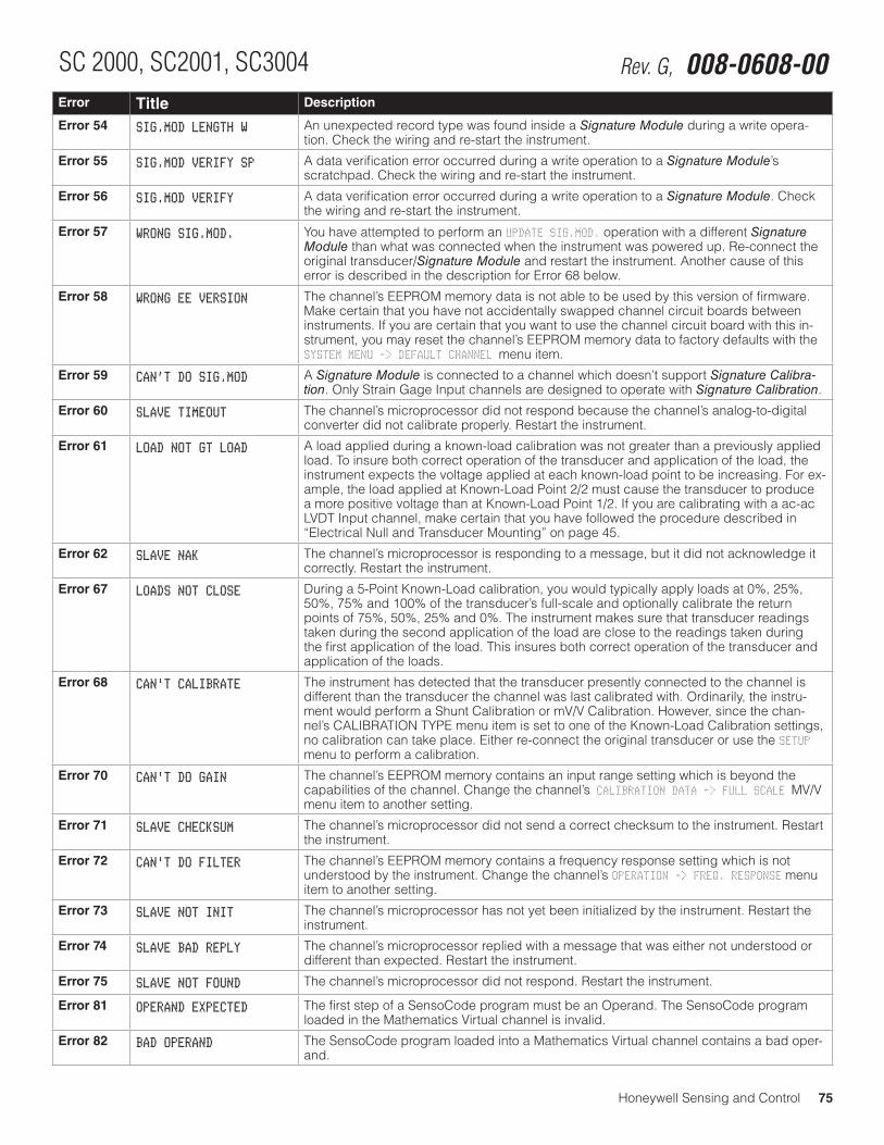
Honeywell Sensing and Control 75
SC 2000, SC2001, SC3004 Rev. G, 008-0608-00Error Title Description
Error 54 SIG.MOD LENGTH W An unexpected record type was found inside a Signature Module during a write opera-tion. Check the wiring and re-start the instrument.
Error 55 SIG.MOD VERIFY SP A data verification error occurred during a write operation to a Signature Module’s scratchpad. Check the wiring and re-start the instrument.
Error 56 SIG.MOD VERIFY A data verification error occurred during a write operation to a Signature Module. Check the wiring and re-start the instrument.
Error 57 WRONG SIG.MOD. You have attempted to perform an UPDATE SIG.MOD. operation with a different Signature Module than what was connected when the instrument was powered up. Re-connect the original transducer/Signature Module and restart the instrument. Another cause of this error is described in the description for Error 68 below.
Error 58 WRONG EE VERSION The channel’s EEPROM memory data is not able to be used by this version of firmware. Make certain that you have not accidentally swapped channel circuit boards between instruments. If you are certain that you want to use the channel circuit board with this in-strument, you may reset the channel’s EEPROM memory data to factory defaults with the SYSTEM MENU -> DEFAULT CHANNEL menu item.
Error 59 CAN’T DO SIG.MOD A Signature Module is connected to a channel which doesn’t support Signature Calibra-tion. Only Strain Gage Input channels are designed to operate with Signature Calibration.
Error 60 SLAVE TIMEOUT The channel’s microprocessor did not respond because the channel’s analog-to-digital converter did not calibrate properly. Restart the instrument.
Error 61 LOAD NOT GT LOAD A load applied during a known-load calibration was not greater than a previously applied load. To insure both correct operation of the transducer and application of the load, the instrument expects the voltage applied at each known-load point to be increasing. For ex-ample, the load applied at Known-Load Point 2/2 must cause the transducer to produce a more positive voltage than at Known-Load Point 1/2. If you are calibrating with a ac-ac LVDT Input channel, make certain that you have followed the procedure described in “Electrical Null and Transducer Mounting” on page 45.
Error 62 SLAVE NAK The channel’s microprocessor is responding to a message, but it did not acknowledge it correctly. Restart the instrument.
Error 67 LOADS NOT CLOSE During a 5-Point Known-Load calibration, you would typically apply loads at 0%, 25%, 50%, 75% and 100% of the transducer’s full-scale and optionally calibrate the return points of 75%, 50%, 25% and 0%. The instrument makes sure that transducer readings taken during the second application of the load are close to the readings taken during the first application of the load. This insures both correct operation of the transducer and application of the loads.
Error 68 CAN'T CALIBRATE The instrument has detected that the transducer presently connected to the channel is different than the transducer the channel was last calibrated with. Ordinarily, the instru-ment would perform a Shunt Calibration or mV/V Calibration. However, since the chan-nel’s CALIBRATION TYPE menu item is set to one of the Known-Load Calibration settings, no calibration can take place. Either re-connect the original transducer or use the SETUP menu to perform a calibration.
Error 70 CAN'T DO GAIN The channel’s EEPROM memory contains an input range setting which is beyond the capabilities of the channel. Change the channel’s CALIBRATION DATA -> FULL SCALE MV/V menu item to another setting.
Error 71 SLAVE CHECKSUM The channel’s microprocessor did not send a correct checksum to the instrument. Restart the instrument.
Error 72 CAN'T DO FILTER The channel’s EEPROM memory contains a frequency response setting which is not understood by the instrument. Change the channel’s OPERATION -> FREQ. RESPONSE menu item to another setting.
Error 73 SLAVE NOT INIT The channel’s microprocessor has not yet been initialized by the instrument. Restart the instrument.
Error 74 SLAVE BAD REPLY The channel’s microprocessor replied with a message that was either not understood or different than expected. Restart the instrument.
Error 75 SLAVE NOT FOUND The channel’s microprocessor did not respond. Restart the instrument.
Error 81 OPERAND EXPECTED The first step of a SensoCode program must be an Operand. The SensoCode program loaded in the Mathematics Virtual channel is invalid.
Error 82 BAD OPERAND The SensoCode program loaded into a Mathematics Virtual channel contains a bad oper-and.
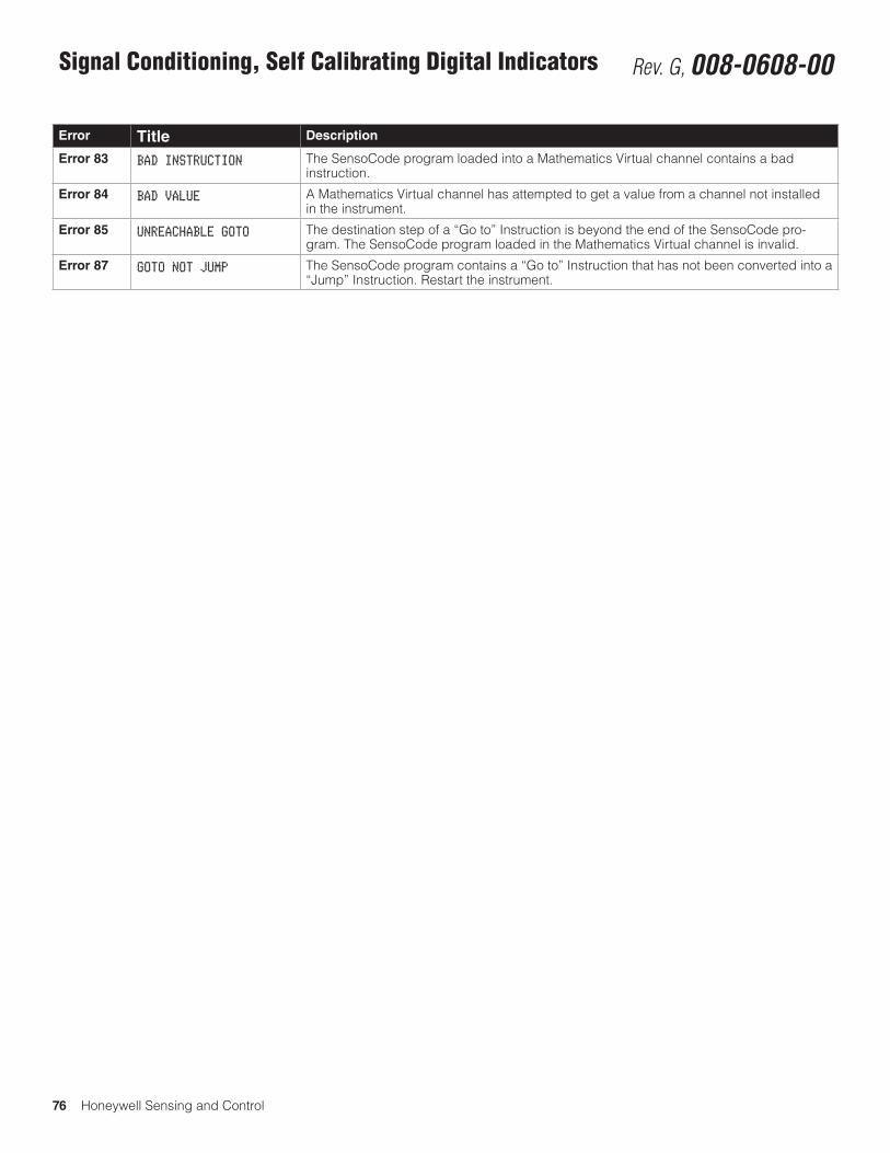
76 Honeywell Sensing and Control
Signal Conditioning, Self Calibrating Digital Indicators Rev. G, 008-0608-00
Error Title Description
Error 83 BAD INSTRUCTION The SensoCode program loaded into a Mathematics Virtual channel contains a bad instruction.
Error 84 BAD VALUE A Mathematics Virtual channel has attempted to get a value from a channel not installed in the instrument.
Error 85 UNREACHABLE GOTO The destination step of a “Go to” Instruction is beyond the end of the SensoCode pro-gram. The SensoCode program loaded in the Mathematics Virtual channel is invalid.
Error 87 GOTO NOT JUMP The SensoCode program contains a “Go to” Instruction that has not been converted into a “Jump” Instruction. Restart the instrument.
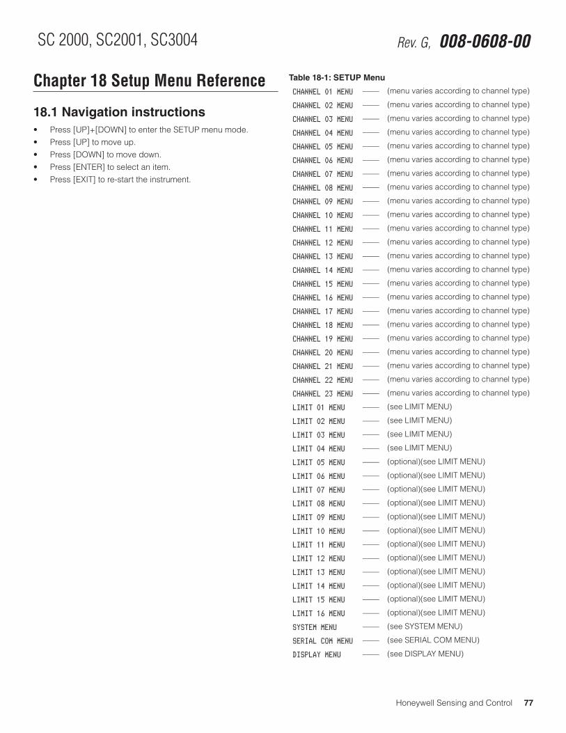
Honeywell Sensing and Control 77
SC 2000, SC2001, SC3004 Rev. G, 008-0608-00
Chapter 18 Setup Menu Reference
18.1 Navigation instructions• Press[UP]+[DOWN]toentertheSETUPmenumode.• Press[UP]tomoveup.• Press[DOWN]tomovedown.• Press[ENTER]toselectanitem.• Press[EXIT]tore-starttheinstrument.
Table 18-1: SETUP Menu
CHANNEL 01 MENU –––– (menu varies according to channel type)
CHANNEL 02 MENU –––– (menu varies according to channel type)
CHANNEL 03 MENU –––– (menu varies according to channel type)
CHANNEL 04 MENU –––– (menu varies according to channel type)
CHANNEL 05 MENU –––– (menu varies according to channel type)
CHANNEL 06 MENU –––– (menu varies according to channel type)
CHANNEL 07 MENU –––– (menu varies according to channel type)
CHANNEL 08 MENU –––– (menu varies according to channel type)
CHANNEL 09 MENU –––– (menu varies according to channel type)
CHANNEL 10 MENU –––– (menu varies according to channel type)
CHANNEL 11 MENU –––– (menu varies according to channel type)
CHANNEL 12 MENU –––– (menu varies according to channel type)
CHANNEL 13 MENU –––– (menu varies according to channel type)
CHANNEL 14 MENU –––– (menu varies according to channel type)
CHANNEL 15 MENU –––– (menu varies according to channel type)
CHANNEL 16 MENU –––– (menu varies according to channel type)
CHANNEL 17 MENU –––– (menu varies according to channel type)
CHANNEL 18 MENU –––– (menu varies according to channel type)
CHANNEL 19 MENU –––– (menu varies according to channel type)
CHANNEL 20 MENU –––– (menu varies according to channel type)
CHANNEL 21 MENU –––– (menu varies according to channel type)
CHANNEL 22 MENU –––– (menu varies according to channel type)
CHANNEL 23 MENU –––– (menu varies according to channel type)
LIMIT 01 MENU –––– (see LIMIT MENU)
LIMIT 02 MENU –––– (see LIMIT MENU)
LIMIT 03 MENU –––– (see LIMIT MENU)
LIMIT 04 MENU –––– (see LIMIT MENU)
LIMIT 05 MENU –––– (optional)(see LIMIT MENU)
LIMIT 06 MENU –––– (optional)(see LIMIT MENU)
LIMIT 07 MENU –––– (optional)(see LIMIT MENU)
LIMIT 08 MENU –––– (optional)(see LIMIT MENU)
LIMIT 09 MENU –––– (optional)(see LIMIT MENU)
LIMIT 10 MENU –––– (optional)(see LIMIT MENU)
LIMIT 11 MENU –––– (optional)(see LIMIT MENU)
LIMIT 12 MENU –––– (optional)(see LIMIT MENU)
LIMIT 13 MENU –––– (optional)(see LIMIT MENU)
LIMIT 14 MENU –––– (optional)(see LIMIT MENU)
LIMIT 15 MENU –––– (optional)(see LIMIT MENU)
LIMIT 16 MENU –––– (optional)(see LIMIT MENU)
SYSTEM MENU –––– (see SYSTEM MENU)
SERIAL COM MENU –––– (see SERIAL COM MENU)
DISPLAY MENU –––– (see DISPLAY MENU)
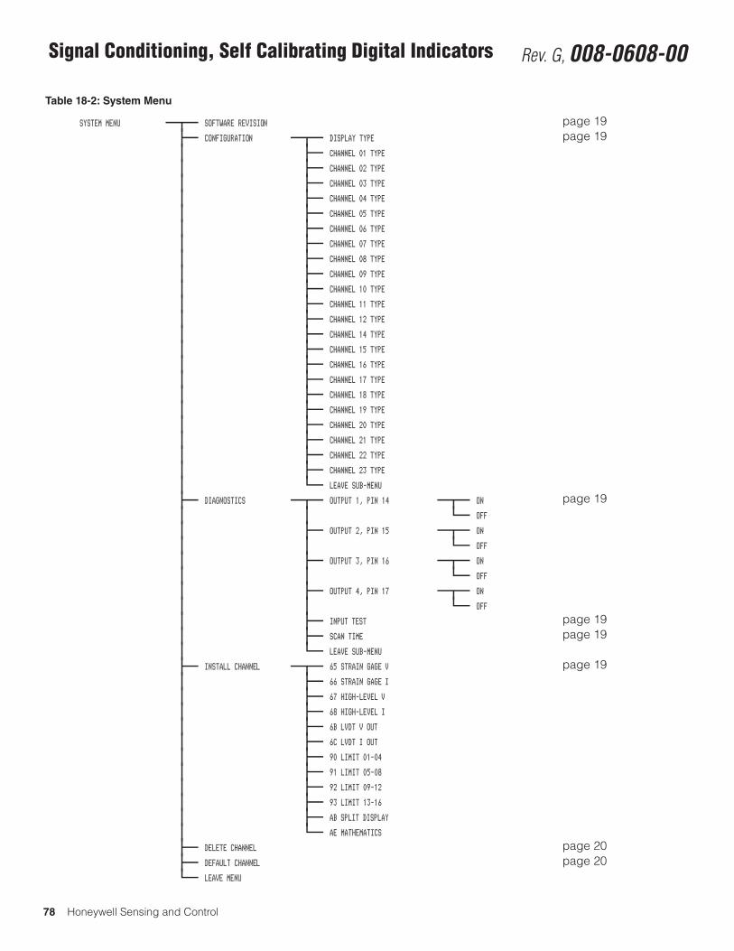
78 Honeywell Sensing and Control
Signal Conditioning, Self Calibrating Digital Indicators Rev. G, 008-0608-00
Table 18-2: System Menu
SYSTEM MENU SOFTWARE REVISION page 19CONFIGURATION DISPLAY TYPE page 19
CHANNEL 01 TYPE
CHANNEL 02 TYPE
CHANNEL 03 TYPE
CHANNEL 04 TYPE
CHANNEL 05 TYPE
CHANNEL 06 TYPE
CHANNEL 07 TYPE
CHANNEL 08 TYPE
CHANNEL 09 TYPE
CHANNEL 10 TYPE
CHANNEL 11 TYPE
CHANNEL 12 TYPE
CHANNEL 14 TYPE
CHANNEL 15 TYPE
CHANNEL 16 TYPE
CHANNEL 17 TYPE
CHANNEL 18 TYPE
CHANNEL 19 TYPE
CHANNEL 20 TYPE
CHANNEL 21 TYPE
CHANNEL 22 TYPE
CHANNEL 23 TYPE
LEAVE SUB-MENU
DIAGNOSTICS OUTPUT 1, PIN 14 ON page 19OFF
OUTPUT 2, PIN 15 ON
OFF
OUTPUT 3, PIN 16 ON
OFF
OUTPUT 4, PIN 17 ON
OFF
INPUT TEST page 19SCAN TIME page 19LEAVE SUB-MENU
INSTALL CHANNEL 65 STRAIN GAGE V page 1966 STRAIN GAGE I
67 HIGH-LEVEL V
68 HIGH-LEVEL I
6B LVDT V OUT
6C LVDT I OUT
90 LIMIT 01-04
91 LIMIT 05-08
92 LIMIT 09-12
93 LIMIT 13-16
AB SPLIT DISPLAY
AE MATHEMATICS
DELETE CHANNEL page 20DEFAULT CHANNEL page 20LEAVE MENU
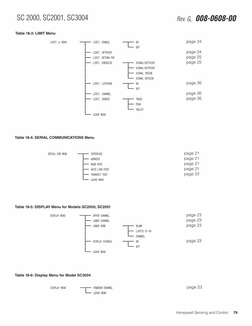
Honeywell Sensing and Control 79
SC 2000, SC2001, SC3004 Rev. G, 008-0608-00
Table 18-3: LIMIT Menu
Table 18-4: SERIAL COMMUNICATIONS Menu
Table 18-5: DISPLAY Menu for Models SC2000, SC2001
Table 18-6: Display Menu for Model SC3004
LIMIT xx MENU LIMIT. ENABLE ON page 24OFF
LIMIT. SETPOINT page 24LIMIT. RETURN PNT page 25LIMIT. ENERGIZE SIGNAL>SETPOINT page 25
SIGNAL<SETPOINT
SIGNAL INSIDE
SIGNAL OUTSIDE
LIMIT. LATCHING ON page 26OFF
LIMIT. CHANNEL page 26LIMIT. SOURCE TRACK page 26
PEAK
VALLEY
LEAVE MENU
DISPLAY MENU POWERON CHANNEL page 23LEAVE MENU
DISPLAY MENU UPPER CHANNEL page 23LOWER CHANNEL page 23LOWER MODE BLANK page 23
LIMITS 01-04
CHANNEL
DISPLAY DISABLE ON page 23OFF
LEAVE MENU
Table 7-13: SERIAL COMMUNICATIONS Menu
SERIAL COM MENU INTERFACE page 21ADDRESS page 21BAUD RATE page 21AUTO LINE-FEED page 21TRANSMIT TEST page 22LEAVE MENU
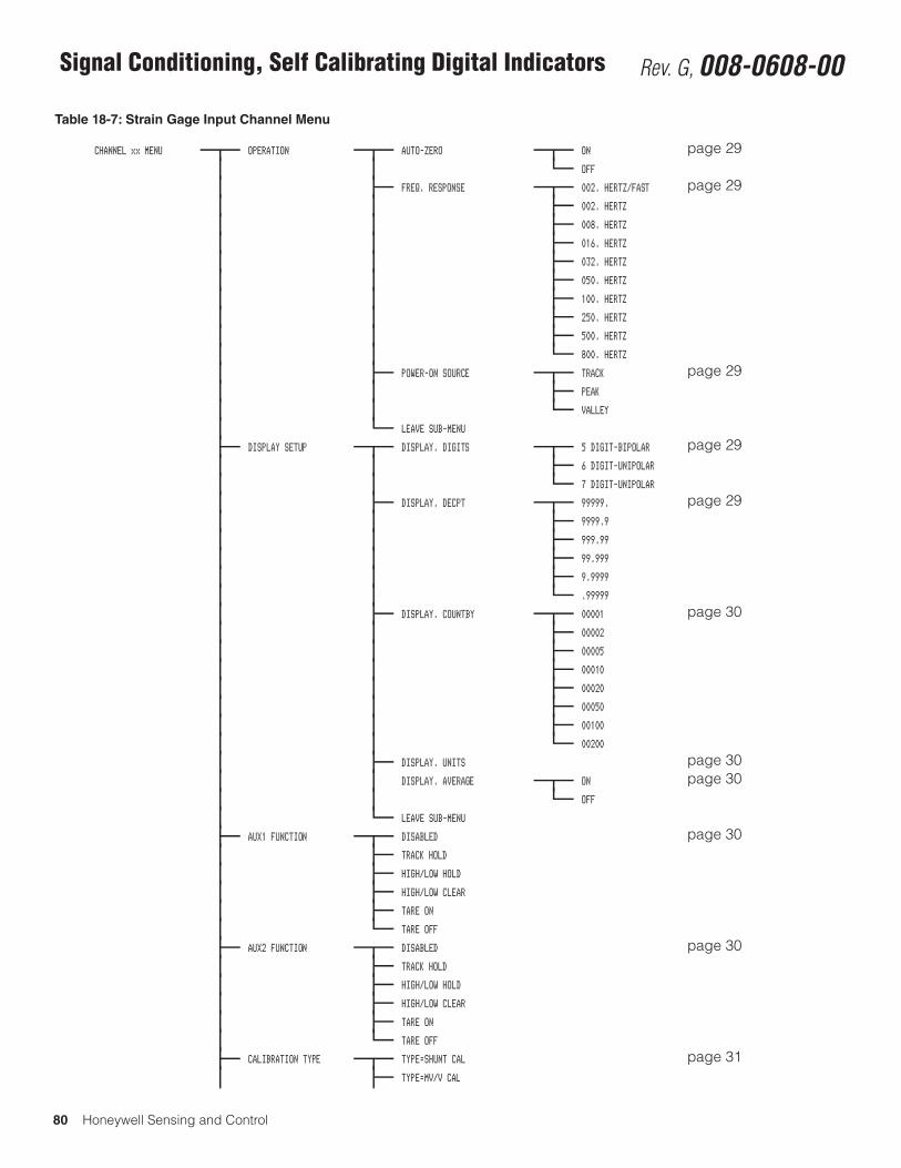
80 Honeywell Sensing and Control
Signal Conditioning, Self Calibrating Digital Indicators Rev. G, 008-0608-00
Table 18-7: Strain Gage Input Channel Menu
CHANNEL xx MENU OPERATION AUTO-ZERO ON page 29OFF
FREQ. RESPONSE 002. HERTZ/FAST page 29002. HERTZ
008. HERTZ
016. HERTZ
032. HERTZ
050. HERTZ
100. HERTZ
250. HERTZ
500. HERTZ
800. HERTZ
POWER-ON SOURCE TRACK page 29PEAK
VALLEY
LEAVE SUB-MENU
DISPLAY SETUP DISPLAY. DIGITS 5 DIGIT-BIPOLAR page 296 DIGIT-UNIPOLAR
7 DIGIT-UNIPOLAR
DISPLAY. DECPT 99999. page 299999.9
999.99
99.999
9.9999
.99999
DISPLAY. COUNTBY 00001 page 3000002
00005
00010
00020
00050
00100
00200
DISPLAY. UNITS page 30DISPLAY. AVERAGE ON page 30
OFF
LEAVE SUB-MENU
AUX1 FUNCTION DISABLED page 30TRACK HOLD
HIGH/LOW HOLD
HIGH/LOW CLEAR
TARE ON
TARE OFF
AUX2 FUNCTION DISABLED page 30TRACK HOLD
HIGH/LOW HOLD
HIGH/LOW CLEAR
TARE ON
TARE OFF
CALIBRATION TYPE TYPE=SHUNT CAL page 31TYPE=MV/V CAL
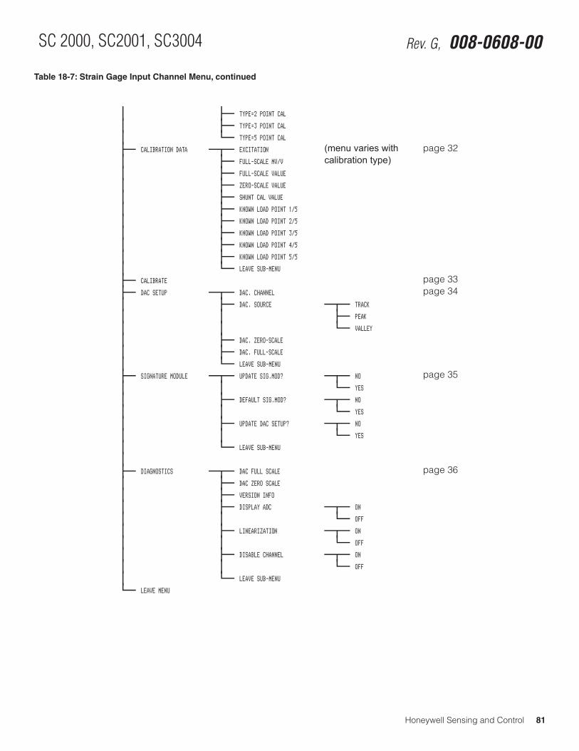
Honeywell Sensing and Control 81
SC 2000, SC2001, SC3004 Rev. G, 008-0608-00
Table 18-7: Strain Gage Input Channel Menu, continued
TYPE=2 POINT CAL
TYPE=3 POINT CAL
TYPE=5 POINT CAL
CALIBRATION DATA EXCITATION (menu varies with page 32FULL-SCALE MV/V calibration type)FULL-SCALE VALUE
ZERO-SCALE VALUE
SHUNT CAL VALUE
KNOWN LOAD POINT 1/5
KNOWN LOAD POINT 2/5
KNOWN LOAD POINT 3/5
KNOWN LOAD POINT 4/5
KNOWN LOAD POINT 5/5
LEAVE SUB-MENU
CALIBRATE page 33DAC SETUP DAC. CHANNEL page 34
DAC. SOURCE TRACK
PEAK
VALLEY
DAC. ZERO-SCALE
DAC. FULL-SCALE
LEAVE SUB-MENU
SIGNATURE MODULE UPDATE SIG.MOD? NO page 35YES
DEFAULT SIG.MOD? NO
YES
UPDATE DAC SETUP? NO
YES
LEAVE SUB-MENU
DIAGNOSTICS DAC FULL SCALE page 36DAC ZERO SCALE
VERSION INFO
DISPLAY ADC ON
OFF
LINEARIZATION ON
OFF
DISABLE CHANNEL ON
OFF
LEAVE SUB-MENU
LEAVE MENU
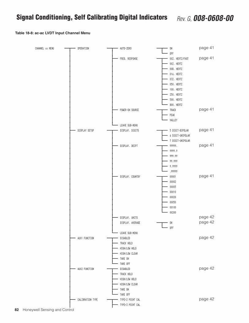
82 Honeywell Sensing and Control
Signal Conditioning, Self Calibrating Digital Indicators Rev. G, 008-0608-00
Table 18-8: ac-ac LVDT Input Channel Menu
CHANNEL xx MENU OPERATION AUTO-ZERO ON page 41OFF
FREQ. RESPONSE 002. HERTZ/FAST page 41002. HERTZ
008. HERTZ
016. HERTZ
032. HERTZ
050. HERTZ
100. HERTZ
250. HERTZ
500. HERTZ
800. HERTZ
POWER-ON SOURCE TRACK page 41PEAK
VALLEY
LEAVE SUB-MENU
DISPLAY SETUP DISPLAY. DIGITS 5 DIGIT-BIPOLAR page 416 DIGIT-UNIPOLAR
7 DIGIT-UNIPOLAR
DISPLAY. DECPT 99999. page 419999.9
999.99
99.999
9.9999
.99999
DISPLAY. COUNTBY 00001 page 4100002
00005
00010
00020
00050
00100
00200
DISPLAY. UNITS page 42DISPLAY. AVERAGE ON page 42
OFF
LEAVE SUB-MENU
AUX1 FUNCTION DISABLED page 42TRACK HOLD
HIGH/LOW HOLD
HIGH/LOW CLEAR
TARE ON
TARE OFF
AUX2 FUNCTION DISABLED page 42TRACK HOLD
HIGH/LOW HOLD
HIGH/LOW CLEAR
TARE ON
TARE OFF
CALIBRATION TYPE TYPE=2 POINT CAL page 42TYPE=3 POINT CAL
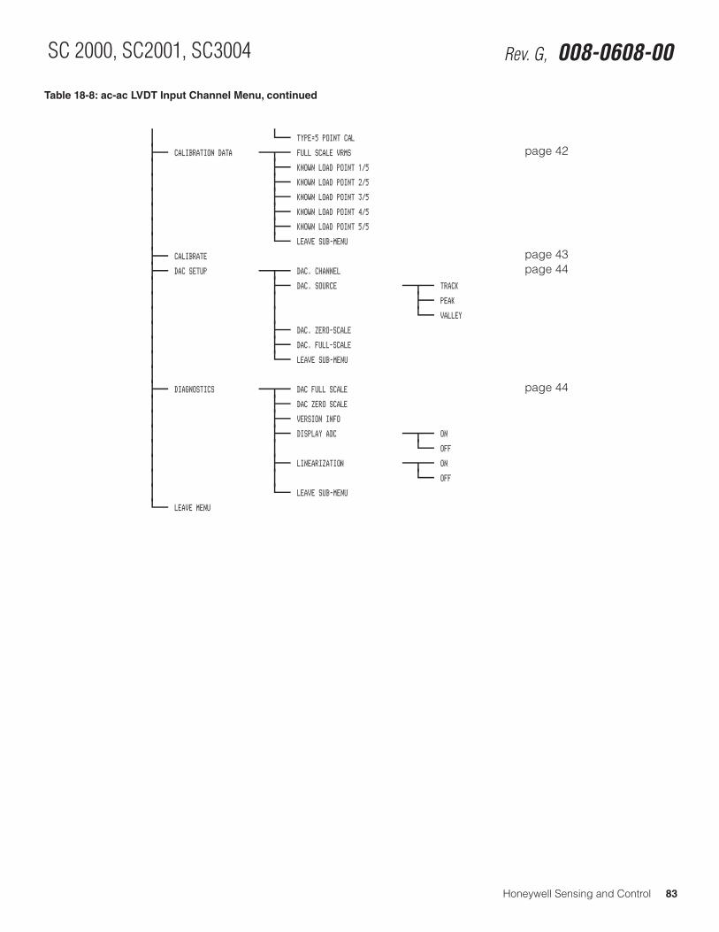
Honeywell Sensing and Control 83
SC 2000, SC2001, SC3004 Rev. G, 008-0608-00
Table 18-8: ac-ac LVDT Input Channel Menu, continued
TYPE=5 POINT CAL
CALIBRATION DATA FULL SCALE VRMS page 42KNOWN LOAD POINT 1/5
KNOWN LOAD POINT 2/5
KNOWN LOAD POINT 3/5
KNOWN LOAD POINT 4/5
KNOWN LOAD POINT 5/5
LEAVE SUB-MENU
CALIBRATE page 43DAC SETUP DAC. CHANNEL page 44
DAC. SOURCE TRACK
PEAK
VALLEY
DAC. ZERO-SCALE
DAC. FULL-SCALE
LEAVE SUB-MENU
DIAGNOSTICS DAC FULL SCALE page 44DAC ZERO SCALE
VERSION INFO
DISPLAY ADC ON
OFF
LINEARIZATION ON
OFF
LEAVE SUB-MENU
LEAVE MENU
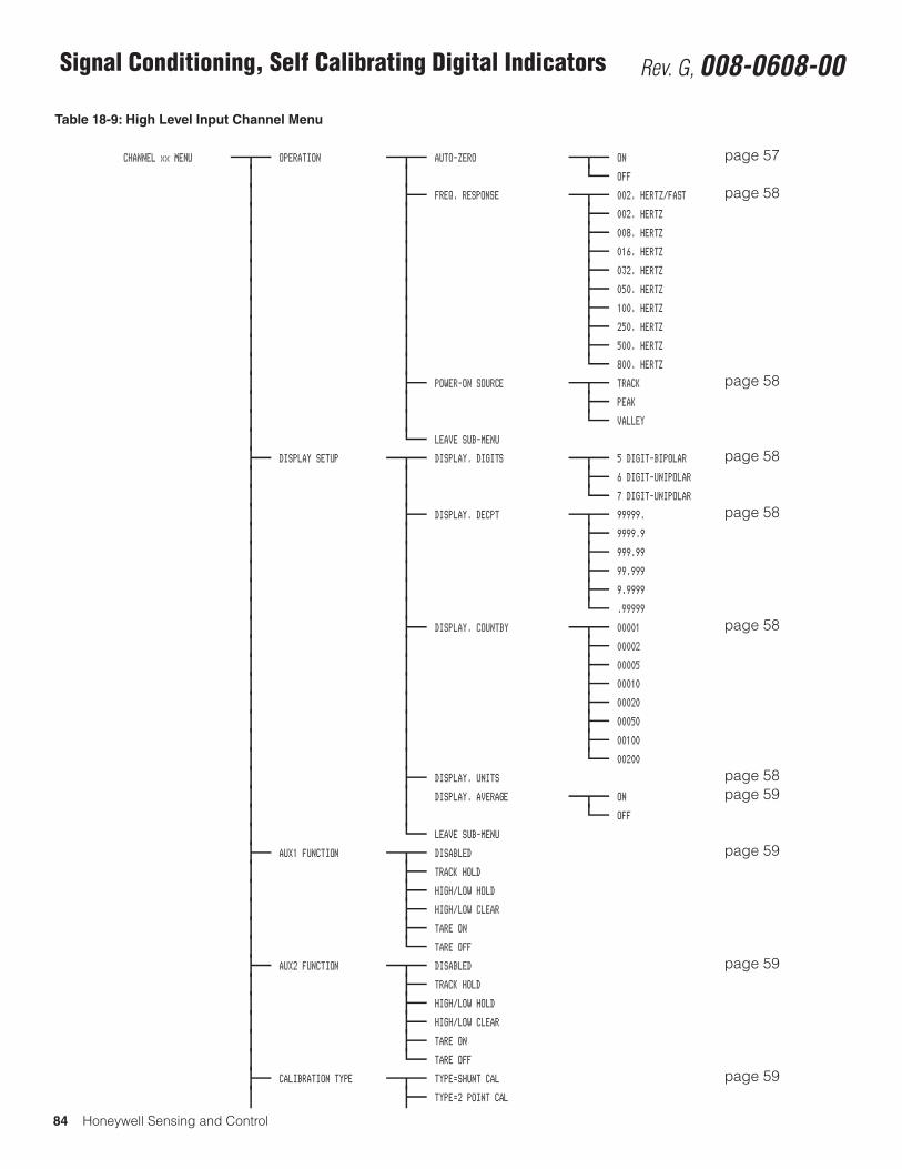
84 Honeywell Sensing and Control
Signal Conditioning, Self Calibrating Digital Indicators Rev. G, 008-0608-00
Table 18-9: High Level Input Channel Menu
CHANNEL xx MENU OPERATION AUTO-ZERO ON page 57OFF
FREQ. RESPONSE 002. HERTZ/FAST page 58002. HERTZ
008. HERTZ
016. HERTZ
032. HERTZ
050. HERTZ
100. HERTZ
250. HERTZ
500. HERTZ
800. HERTZ
POWER-ON SOURCE TRACK page 58PEAK
VALLEY
LEAVE SUB-MENU
DISPLAY SETUP DISPLAY. DIGITS 5 DIGIT-BIPOLAR page 586 DIGIT-UNIPOLAR
7 DIGIT-UNIPOLAR
DISPLAY. DECPT 99999. page 589999.9
999.99
99.999
9.9999
.99999
DISPLAY. COUNTBY 00001 page 5800002
00005
00010
00020
00050
00100
00200
DISPLAY. UNITS page 58DISPLAY. AVERAGE ON page 59
OFF
LEAVE SUB-MENU
AUX1 FUNCTION DISABLED page 59TRACK HOLD
HIGH/LOW HOLD
HIGH/LOW CLEAR
TARE ON
TARE OFF
AUX2 FUNCTION DISABLED page 59TRACK HOLD
HIGH/LOW HOLD
HIGH/LOW CLEAR
TARE ON
TARE OFF
CALIBRATION TYPE TYPE=SHUNT CAL page 59TYPE=2 POINT CAL
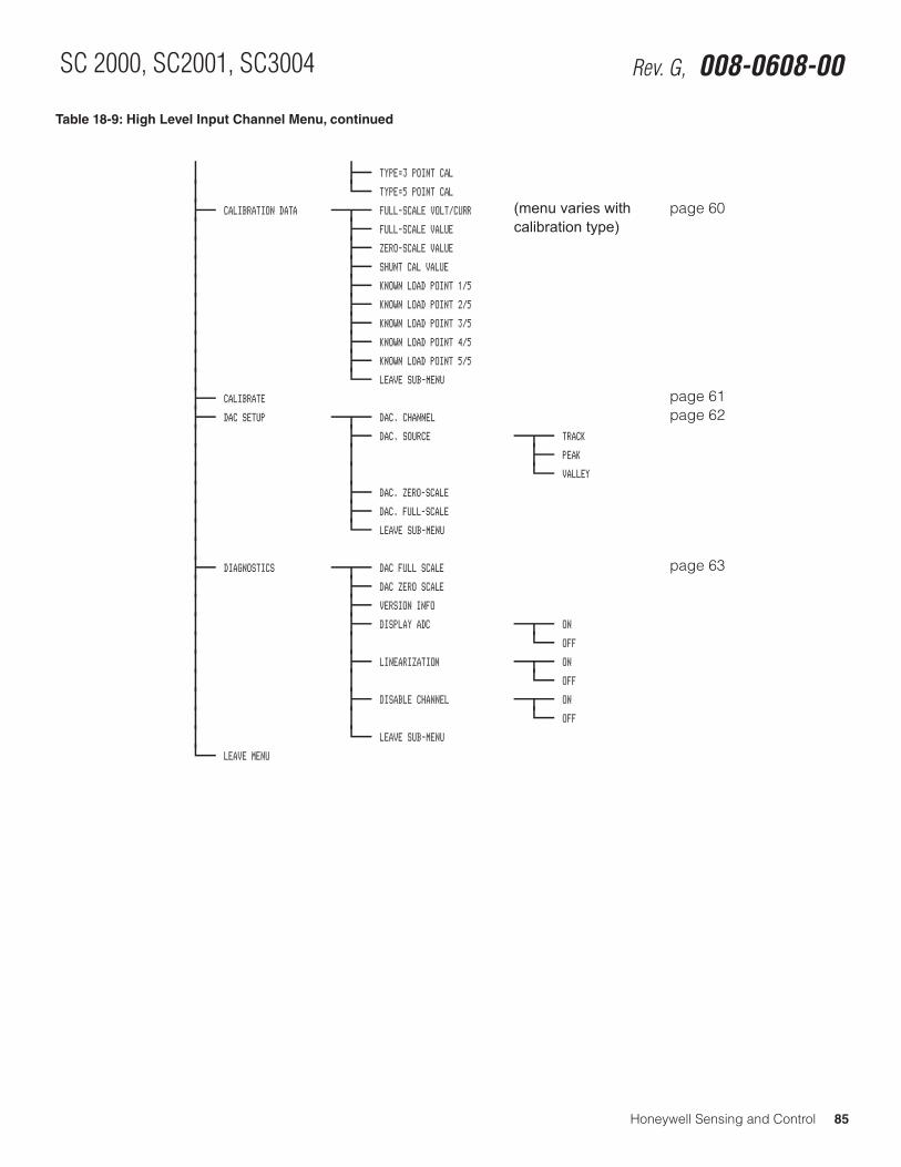
Honeywell Sensing and Control 85
SC 2000, SC2001, SC3004 Rev. G, 008-0608-00
Table 18-9: High Level Input Channel Menu, continued
TYPE=3 POINT CAL
TYPE=5 POINT CAL
CALIBRATION DATA FULL-SCALE VOLT/CURR (menu varies with page 60FULL-SCALE VALUE calibration type)ZERO-SCALE VALUE
SHUNT CAL VALUE
KNOWN LOAD POINT 1/5
KNOWN LOAD POINT 2/5
KNOWN LOAD POINT 3/5
KNOWN LOAD POINT 4/5
KNOWN LOAD POINT 5/5
LEAVE SUB-MENU
CALIBRATE page 61DAC SETUP DAC. CHANNEL page 62
DAC. SOURCE TRACK
PEAK
VALLEY
DAC. ZERO-SCALE
DAC. FULL-SCALE
LEAVE SUB-MENU
DIAGNOSTICS DAC FULL SCALE page 63DAC ZERO SCALE
VERSION INFO
DISPLAY ADC ON
OFF
LINEARIZATION ON
OFF
DISABLE CHANNEL ON
OFF
LEAVE SUB-MENU
LEAVE MENU
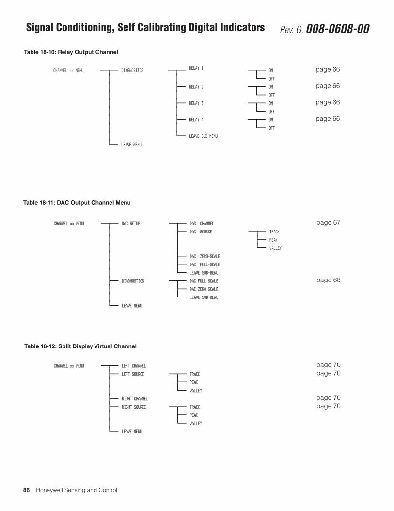
86 Honeywell Sensing and Control
Signal Conditioning, Self Calibrating Digital Indicators Rev. G, 008-0608-00
Table 18-10: Relay Output Channel
Table 18-11: DAC Output Channel Menu
Table 18-12: Split Display Virtual Channel
CHANNEL xx MENU DIAGNOSTICS RELAY 1 ON page 66OFF
RELAY 2 ON page 66OFF
RELAY 3 ON page 66OFF
RELAY 4 ON page 66OFF
LEAVE SUB-MENU
LEAVE MENU
CHANNEL xx MENU DAC SETUP DAC. CHANNEL page 67DAC. SOURCE TRACK
PEAK
VALLEY
DAC. ZERO-SCALE
DAC. FULL-SCALE
LEAVE SUB-MENU
DIAGNOSTICS DAC FULL SCALE page 68DAC ZERO SCALE
LEAVE SUB-MENU
LEAVE MENU
CHANNEL xx MENU LEFT CHANNEL page 70LEFT SOURCE TRACK page 70
PEAK
VALLEY
RIGHT CHANNEL page 70RIGHT SOURCE TRACK page 70
PEAK
VALLEY
LEAVE MENU
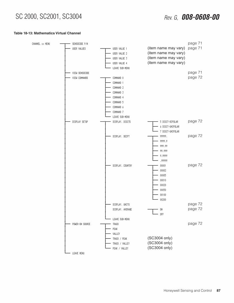
Honeywell Sensing and Control 87
SC 2000, SC2001, SC3004 Rev. G, 008-0608-00
Table 18-13: Mathematics Virtual Channel
CHANNEL xx MENU SENSOCODE P/N page 71USER VALUES USER VALUE 1 (item name may vary) page 71
USER VALUE 2 (item name may vary)USER VALUE 3 (item name may vary)USER VALUE 4 (item name may vary)LEAVE SUB-MENU
VIEW SENSOCODE page 71VIEW COMMANDS COMMAND 0 page 72
COMMAND 1
COMMAND 2
COMMAND 3
COMMAND 4
COMMAND 5
COMMAND 6
COMMAND 7
LEAVE SUB-MENU
DISPLAY SETUP DISPLAY. DIGITS 5 DIGIT-BIPOLAR page 726 DIGIT-UNIPOLAR
7 DIGIT-UNIPOLAR
DISPLAY. DECPT 99999. page 729999.9
999.99
99.999
9.9999
.99999
DISPLAY. COUNTBY 00001 page 7200002
00005
00010
00020
00050
00100
00200
DISPLAY. UNITS page 72DISPLAY. AVERAGE ON page 72
OFF
LEAVE SUB-MENU
POWER-ON SOURCE TRACK page 72PEAK
VALLEY
TRACK / PEAK (SC3004 only)TRACK / VALLEY (SC3004 only)PEAK / VALLEY (SC3004 only)
LEAVE MENU
88 Honeywell Sensing and Control
Signal Conditioning, Self Calibrating Digital Indicators Rev. G, 008-0608-00Index2-wire Current Amps 1-wire Shunt Cal . . . . . . . . . . . . . . . . . . . 542-wire Current Amps Buff. Shunt Cal . . . . . . . . . . . . . . . . . . . . . 533-wire Current Amplifiers . . . . . . . . . . . . . . . . . . . . . . . . . . . . . . 523-wire Voltage Amplifiers . . . . . . . . . . . . . . . . . . . . . . . . . . . . . . 503-wire Voltage Amps with 1-wire Shunt Cal . . . . . . . . . . . . . . . . 51
AAC/AC-LVDT Input Channel . . . . . . . . . . . . . . . . . . . . . 39, 82-83ADDRESS Menu Item . . . . . . . . . . . . . . . . . . . . . . . . . . . . . . . . 21Analog Output Configuration . . . . . . . . . . . . . . . . . . . . . . . . 36, 46Analog Output Configuration, DAC Output Channel . . . . . . . . . 68AUTO LINE-FEED Menu Item . . . . . . . . . . . . . . . . . . . . . . . . . . 21AUXn FUNCTION, AC/AC LVDT Input. . . . . . . . . . . . . . . . . . . . 42AUXn FUNCTION, High Level Input . . . . . . . . . . . . . . . . . . . . . 59AUXn FUNCTION, Strain-Gage Input . . . . . . . . . . . . . . . . . . . . 30
B BAUD RATE Menu Item . . . . . . . . . . . . . . . . . . . . . . . . . . . . . . . 21Bi-polar Voltage Amplifiers . . . . . . . . . . . . . . . . . . . . . . . . . . . . 49
CCALIBRATE, AC/AC LVDT Input . . . . . . . . . . . . . . . . . . . . . . . . 43CALIBRATE, High Level Input . . . . . . . . . . . . . . . . . . . . . . . . . . 61CALIBRATE, Strain-Gage Input . . . . . . . . . . . . . . . . . . . . . . . . . 33CALIBRATION DATA, AC/AC LVDT Input . . . . . . . . . . . . . . . . . 42CALIBRATION DATA, High Level Input . . . . . . . . . . . . . . . . . . . 60CALIBRATION DATA, Strain-Gage Input . . . . . . . . . . . . . . . . . . 32Calibration . . . . . . . . . . . . . . . . . . . . . . . . . . . . . . . . . . . . . . . . . . 5Calibration Procedure . . . . . . . . . . . . . . . . . . . . . . . . . . 28, 40, 56CALIBRATION TYPE, AC/AC LVDT Input . . . . . . . . . . . . . . . . . 42CALIBRATION TYPE, High Level Input . . . . . . . . . . . . . . . . . . . 59CALIBRATION TYPE, Strain-Gage Input . . . . . . . . . . . . . . . . . . 31CHANNEL button . . . . . . . . . . . . . . . . . . . . . . . . . . . . . . . . . . . . 7Channel Menu Items . . . . . . . . . . . . . . . . . . . . . . . . . . . 36, 46, 63Channel Menu . . . . . . . . . . . . . . . . . . . . . . . . . . . . . . . . . . . 29, 41Channel Menu, DAC Output Channel . . . . . . . . . . . . . . . . . 66-68Channel Menu, Mathematics Virtual Channel . . . . . . . . . . . . . . 71Channel Menu, Split Display Virtual Channel . . . . . . . . . . . . . . 70Chassis Models . . . . . . . . . . . . . . . . . . . . . . . . . . . . . . . . . . . . . . 9CLEAR button . . . . . . . . . . . . . . . . . . . . . . . . . . . . . . . . . . . . . . . 7Communications Guide . . . . . . . . . . . . . . . . . . . . . . . . . . . . . . . . 2Communications Protocol . . . . . . . . . . . . . . . . . . . . . . . . . . . . . 21CONFIGURATION Sub-Menu . . . . . . . . . . . . . . . . . . . . . . . . . . 19Connecting Transducerl . . . . . . . . . . . . . . . . . . . . . . . . . . . . . . . 4Customer Information Sheet . . . . . . . . . . . . . . . . . . . . . . . . . . . . 2
DDAC Output Channel . . . . . . . . . . . . . . . . . . . . . . . . . . . . . . 66, 86DAC SETUP, AC/AC LVDT Input . . . . . . . . . . . . . . . . . . . . . . . . 44DAC SETUP, DAC Output Channel . . . . . . . . . . . . . . . . . . . . . . 67DAC SETUP, High Level Input . . . . . . . . . . . . . . . . . . . . . . . . . . 62DAC SETUP, Strain-Gage Input . . . . . . . . . . . . . . . . . . . . . . . . . 34DEFAULT CHANNEL Menu Item . . . . . . . . . . . . . . . . . . . . . . . . 20DELETE CHANNEL Menu Item . . . . . . . . . . . . . . . . . . . . . . . . . 20DIAGNOSTICS Sub-Menu . . . . . . . . . . . . . . . . . . . . . . . . . . . . . 19
DIAGNOSTICS, AC/AC LVDT Input . . . . . . . . . . . . . . . . . . . . . . 44DIAGNOSTICS, DAC Output Channel . . . . . . . . . . . . . . . . 66, 68DIAGNOSTICS, High Level Input . . . . . . . . . . . . . . . . . . . . . . . 63DIAGNOSTICS, Strain-Gage Input . . . . . . . . . . . . . . . . . . . . . . 36DISPLAY DISABLE Menu Item . . . . . . . . . . . . . . . . . . . . . . . . . 23Display Menu . . . . . . . . . . . . . . . . . . . . . . . . . . . . . . . . . . . . 23, 79DISPLAY SETUP, AC/AC LVDT Input . . . . . . . . . . . . . . . . . . . . . 41DISPLAY SETUP, High Level Input . . . . . . . . . . . . . . . . . . . . . . 58DISPLAY SETUP, Mathematics Virtual Channel . . . . . . . . . . . . 72DISPLAY SETUP, Strain-Gage Input . . . . . . . . . . . . . . . . . . . . . 29
E Electrical Null and Transducer Mounting . . . . . . . . . . . . . . . . . 45Error Message List . . . . . . . . . . . . . . . . . . . . . . . . . . . . . . . . . . 73Error Messages . . . . . . . . . . . . . . . . . . . . . . . . . 37, 47, 64, 69, 73ERROR mode . . . . . . . . . . . . . . . . . . . . . . . . . . . . . . . . . . . . . . . 7Excitation and Signal Jumpers . . . . . . . . . . . . . . . . . . . . . . . . . 56
FFirst Channel . . . . . . . . . . . . . . . . . . . . . . . . . . . . . . . . . . . . . . . 65Fourth Channel . . . . . . . . . . . . . . . . . . . . . . . . . . . . . . . . . . . . . 65Function Input Pins . . . . . . . . . . . . . . . . . . . . . . . . . . . . . . . . . . 18
GGetting Started . . . . . . . . . . . . . . . . . . . . . . . . . . . . . . . . . . . . . . 4
HHigh-Level Input Channel . . . . . . . . . . . . . . . . . . . . . . . 48, 84-85
IIndicator Lights . . . . . . . . . . . . . . . . . . . . . . . . . . . . . . . . . . . . . . 7INITIALIZE Mode . . . . . . . . . . . . . . . . . . . . . . . . . . . . . . . . . . . . . 6INSTALL CHANNEL Menu Item . . . . . . . . . . . . . . . . . . . . . . . . . 19INTERFACE Menu Item . . . . . . . . . . . . . . . . . . . . . . . . . . . . . . . 21
JJumpers . . . . . . . . . . . . . . . . . . . . . . . . . . . . . . . . . . . . . . . . . . . 56
LLEAVE Menu Item . . . . . . . . . . . . . . . . . . . . . . . . . . . . . . . . 22, 26Limit Menu . . . . . . . . . . . . . . . . . . . . . . . . . . . . . . . . . . . . . . 24, 79Limit Operation . . . . . . . . . . . . . . . . . . . . . . . . . . . . . . . . . . . . . 24Limit Output Pins . . . . . . . . . . . . . . . . . . . . . . . . . . . . . . . . . . . . 18LIMIT.CHANNEL Menu Item . . . . . . . . . . . . . . . . . . . . . . . . . . . 26LIMIT.ENABLE Menu Item . . . . . . . . . . . . . . . . . . . . . . . . . . . . 24LIMIT.ENERGIZE Menu Item . . . . . . . . . . . . . . . . . . . . . . . . . . . 25LIMIT.LATCHING Menu Item . . . . . . . . . . . . . . . . . . . . . . . . . . . 26LIMIT.RETURN PNT Menu Item . . . . . . . . . . . . . . . . . . . . . . . . . 25LIMIT.SETPOINT Menu Item . . . . . . . . . . . . . . . . . . . . . . . . . . . 24LIMIT.SOURCE Menu Item . . . . . . . . . . . . . . . . . . . . . . . . . . . . 26Limits, Set Points and Return Points . . . . . . . . . . . . . . . . . . . . . 24Low Voltage dc-dc LVDTs . . . . . . . . . . . . . . . . . . . . . . . . . . . . . 55LOWER CHANNEL Menu Item . . . . . . . . . . . . . . . . . . . . . . . . . 23LOWER MODE Menu Item . . . . . . . . . . . . . . . . . . . . . . . . . . . . 23
Honeywell Sensing and Control 89
SC 2000, SC2001, SC3004 Rev. G, 008-0608-00
M Mathematics Virtual Channel . . . . . . . . . . . . . . . . . . . . . . . 71, 87Model SC2000 Bench Mounting . . . . . . . . . . . . . . . . . . . . . . . . 11Model SC2000 Case Removal . . . . . . . . . . . . . . . . . . . . . . . . . 11Model SC2000 Cleaning . . . . . . . . . . . . . . . . . . . . . . . . . . . . . . 12Model SC2000 External Arrangement . . . . . . . . . . . . . . . . . . . . 10Model SC2000 Fuse Replacement . . . . . . . . . . . . . . . . . . . . . . 12Model SC2000 Internal Arrangement . . . . . . . . . . . . . . . . . . . . 12Model SC2000 Panel Mounting . . . . . . . . . . . . . . . . . . . . . . . . . 11Model SC2000 Rack Mounting . . . . . . . . . . . . . . . . . . . . . . . . . 11Model SC2000 Rear Panel . . . . . . . . . . . . . . . . . . . . . . . . . . . . 11Model SC2000 Vehicle Power Option . . . . . . . . . . . . . . . . . . . . 12Model SC2001 Case Removal . . . . . . . . . . . . . . . . . . . . . . . . . 14Model SC2001 Cleaning . . . . . . . . . . . . . . . . . . . . . . . . . . . . . . 14Model SC2001 External Arrangement . . . . . . . . . . . . . . . . . . . . 13Model SC2001 Front Panel . . . . . . . . . . . . . . . . . . . . . . . . . . . . 13Model SC2001 Fuse Replacement . . . . . . . . . . . . . . . . . . . . . . 14Model SC2001 Internal Arrangement . . . . . . . . . . . . . . . . . . . . 14Model SC2001 Vehicle Power Option . . . . . . . . . . . . . . . . . . . . 14Model SC3004 Bench Mounting . . . . . . . . . . . . . . . . . . . . . . . . 15Model SC3004 Case Removal . . . . . . . . . . . . . . . . . . . . . . . . . 15Model SC3004 Cleaning . . . . . . . . . . . . . . . . . . . . . . . . . . . . . . 16Model SC3004 External Arrangement . . . . . . . . . . . . . . . . . . . . 15Model SC3004 Fuse Replacement . . . . . . . . . . . . . . . . . . . . . . 16Model SC3004 Internal Arrangement . . . . . . . . . . . . . . . . . . . . 16Model SC3004 Panel Mounting . . . . . . . . . . . . . . . . . . . . . . . . . 15Model SC3004 Rear Panel . . . . . . . . . . . . . . . . . . . . . . . . . 15-16
N Navigation Instructions . . . . . . . . . . . . . . . . . . . . . . . . . . . . . . . 77
O Operating Modes . . . . . . . . . . . . . . . . . . . . . . . . . . . . . . . . . . . . 6OPERATION, AC/AC LVDT Input . . . . . . . . . . . . . . . . . . . . . . . . 41OPERATION, High Level Input . . . . . . . . . . . . . . . . . . . . . . . . . 57OPERATION, Strain-Gage Input . . . . . . . . . . . . . . . . . . . . . . . . 29Output Selection . . . . . . . . . . . . . . . . . . . . . . . . . . . . . . 36, 46, 63Output Selection, DAC Output Channel . . . . . . . . . . . . . . . . . . 68Output Type . . . . . . . . . . . . . . . . . . . . . . . . . . . . . . . . . . 36, 46, 63Output Type, DAC Output Channel . . . . . . . . . . . . . . . . . . . . . . 68
PPOWER-ON CHANNEL Menu Item . . . . . . . . . . . . . . . . . . . . . . 23POWER-ON SOURCE, Mathematics Virtual Channel . . . . . . . . 72Problems and Solutions . . . . . . . . . . . . . . . . . . . . . . 37, 47, 64, 69
R Relay Output Channel . . . . . . . . . . . . . . . . . . . . . . . . . . . . . 65, 86Required Parts and Information . . . . . . . . . . . . . . . . . . . . . . . . . 4RS-232 vs. RS-485 . . . . . . . . . . . . . . . . . . . . . . . . . . . . . . . . . . 21RUN Mode Display . . . . . . . . . . . . . . . . . . . . . . . . . . . . . . . . . . . 6RUN Mode . . . . . . . . . . . . . . . . . . . . . . . . . . . . . . . . . . . . . . . . . . 6
S SC Series Channel Types . . . . . . . . . . . . . . . . . . . . . . . . . . . . . . 2SC Series Chassis Models . . . . . . . . . . . . . . . . . . . . . . . . . . . . . 2SC Series Features . . . . . . . . . . . . . . . . . . . . . . . . . . . . . . . . . . . 2Scan Time . . . . . . . . . . . . . . . . . . . . . . . . . . . . . . . . . . . . . . . . . 24Second Channel . . . . . . . . . . . . . . . . . . . . . . . . . . . . . . . . . . . . 65Serial Com Menu . . . . . . . . . . . . . . . . . . . . . . . . . . . . . . . . . 21, 79Serial Communications . . . . . . . . . . . . . . . . . . . . . . . . . . . . . . . 21Setup Menu Reference . . . . . . . . . . . . . . . . . . . . . . . . . . . . . . . 77SETUP Menus, Enter Information . . . . . . . . . . . . . . . . . . . . . . . . 5SETUP mode . . . . . . . . . . . . . . . . . . . . . . . . . . . . . . . . . . . . . . . . 7Setup Procedure . . . . . . . . . . . . . . . . . . . . . . . . . . . . . . . . . . . . 65Setup Procedure, DAC Output Channel . . . . . . . . . . . . . . . . . . 67Setup, Mathematics Virtual Channel . . . . . . . . . . . . . . . . . . . . . 71Setup, Split Display Virtual Channel . . . . . . . . . . . . . . . . . . . . . 70Signature Calibration . . . . . . . . . . . . . . . . . . . . . . . . . . . . . . . . . . 3SIGNATURE MODULE, Strain-Gage Input . . . . . . . . . . . . . . . . 35SOFTWARE REVISION Menu Item . . . . . . . . . . . . . . . . . . . . . . 19Specifications . . . . . . . . . . . . . . . . . . . . . . . . . . . . . . . . . 9, 40, 65Specifications, DAC Output Channel . . . . . . . . . . . . . . . . . . . . 67Split Display Virtual Channel . . . . . . . . . . . . . . . . . . . . . . . . 70, 86Strain-Gage Input Channel . . . . . . . . . . . . . . . . . . . . . . 26, 80-81Supplemental Instructions . . . . . . . . . . . . . . . . . . . . . . . . . . . . . . 2System Connector . . . . . . . . . . . . . . . . . . . . . . . . . . . . . . . . . . . 17System Menu . . . . . . . . . . . . . . . . . . . . . . . . . . . . . . . . . . . . 19, 78
T TARE button . . . . . . . . . . . . . . . . . . . . . . . . . . . . . . . . . . . . . . . . . 7Third Channel . . . . . . . . . . . . . . . . . . . . . . . . . . . . . . . . . . . . . . 65TRANSMIT TEST Menu Item . . . . . . . . . . . . . . . . . . . . . . . . . . . 22Troubleshooting . . . . . . . . . . . . . . . . . . . . . . 37, 47, 64, 69, 70, 72Turning on the Instrument . . . . . . . . . . . . . . . . . . . . . . . . . . . . . . 4
UUPPER CHANNEL Menu Item . . . . . . . . . . . . . . . . . . . . . . . . . . 23
VVALUE button . . . . . . . . . . . . . . . . . . . . . . . . . . . . . . . . . . . . . . . 6
W Wiring . . . . . . . . . . . . . . . . . . . . . . . . . . . . . . . . . . . . . . 21, 65, 66
008-0608-00 IL50 GLO Printed in USA.May 2012© 2012 Honeywell International Inc. All rights reserved.
Signal Conditioning, Self Calibrating Digital Indicators 008-0608-00Warranty. Honeywell warrants goods of its manufacture as being free of defective materials and faulty workmanship. Honeywell’s standard product warranty applies unless agreed to otherwise by Honeywell in writing; please refer to your order acknowledgement or consult your local sales office for specific warranty details. If warranted goods are returned to Honeywell during the period of coverage, Honeywell will repair or replace, at its option, without charge those items it finds defective. The foregoing is buyer’s sole remedy and is in lieu of all warranties, expressed or implied, including those of merchantability and fitness for a particular purpose. In no event shall Honeywell be liable for consequential, special, or indirect damages.
While we provide application assistance personally, through our literature and the Honeywell web site, it is up to the customer to determine the suitability of the product in the application.
Specifications may change without notice. The information we supply is believed to be accurate and reliable as of this printing. However, we assume no responsibility for its use.
Find out more
Honeywell serves its customers
through a worldwide network of
sales offices, representatives
and distributors. For application
assistance, current specifica-
tions, pricing or name of the
nearest Authorized Distributor,
contact your local sales office.
To learn more about Honeywell’s
test and measurement products,
call +1-614-850-5000, visit
http://measurementsensors.
honeywell.com, or e-mail inqui-
ries to [email protected]
Sensing and Control
Honeywell
1985 Douglas Drive North
Golden Valley, MN 55422
www.honeywell.com