Embed Size (px)
Citation preview
1
VL LFL ATTIKASTAR DRUCK ENG
*Can be omitted with bituminous roof sealing sheets.
LORO-ATTIKASTAR® siphonic drains consist of the drain body and the stainless steel suction cover.
with clamping flange for
bituminous and plastic sealing
sheets
DN 70
Pressure flow
System overview
LORO-ATTIKASTAR® scupper rainwater drainage
Main drain Emergency drain
Installation instructionsLORO-ATTIKASTAR® siphonic drainswith clamping flange, for pressure flowfor bituminous or plastic roof sealing sheets, according to EN 1253, steel, hot-dip galvanised
Construction diagramMain drainage system Emergency drainage system
Hexagonal bolts
Hexagonal nuts M12 with plastic caps
and washers
Loose flange
Drain pot
Suction cover
Compression seal*
Base plate
Weir
LORO flat roof drainage systems
Installation LORO-ATTIKASTAR® siphonic drains
13228.070X
13779.CC0X 13766.CC0X
13517.DCCX
LORO sliding flangefor bonding
the bituminous or plastic
vapour barrier
Y-shaped jointfor combining
the double pipe into
the downpipe
1 LORO-ATTIKASTAR®
2 LORO sliding flange3 LORO Y-shaped joint4 LORO-X rainwater downpipe5 LORO rain standpipe
1
2
3
4
5
Data sheet: LX 803 Data sheet: LX 766
Please download data sheets from www.loro.de.
Holes for fastening
2
VL LFL ATTIKASTAR DRUCK ENG
LORO flat roof drainage systems
Installation LORO-ATTIKASTAR® siphonic drains
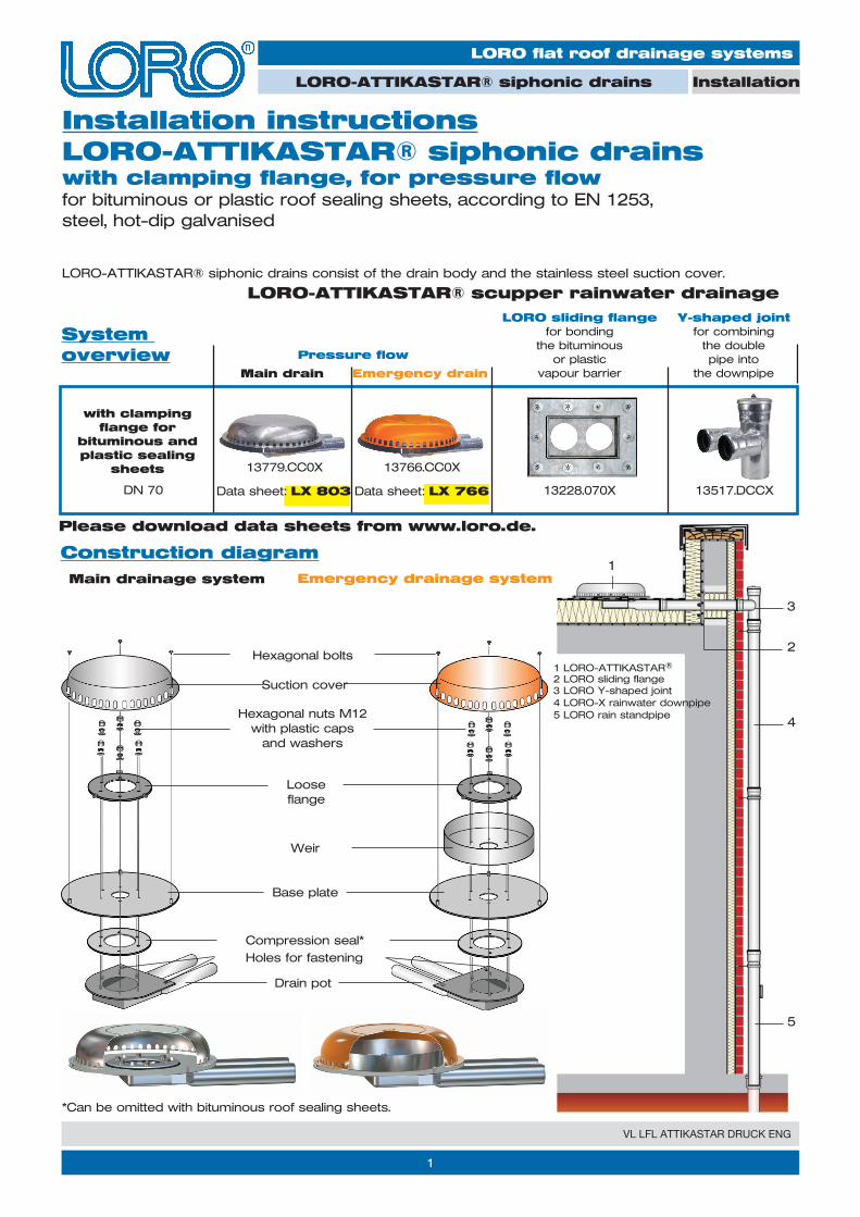
1.2 Drill 10 mm diameter holes for sliding flange (fig. 2). Note: the dimensions given in Table 2 must be maintained!
Note: the thickness of the thermal insulation must be at least 180 mm, otherwise the use of the double-pipe sliding flange is not possible!
1.3 Fasten the sliding flange by means of a screwdriver (fig. 3).
1.1 Make the parapet opening according to Table 1 (Figure 1). Make the hole as far as the bare slab so that the roof space can be drained during the construction phase. According to flat roof regulations, the lateral distance from the outer edge of the drain flange to the upstand of the building must be at least 300 mm.
1.) Specifying the parapet opening, specifying the fitting height, bonding the LORO sliding flange in the vapour barrier
Figure 1a
h
Figure 2
Table 1
a
h
y
300
DN 70
*w = thickness of the thermal insulation in mm
1.4 Use a hole punch to make 10 mm diameter holes in the connecting sleeve for the threaded bolts to pass through. The loose flange can be used as a template. Spread out the bituminous/EPDM compound or plastic connecting sleeve manufactured on-site and attach it to the substrate. Do not allow creases to form (fig. 4). Note: the connecting sleeve must not be damaged.
1.5 Unroll the bituminous or plastic vapour barrier sheet. Make a rectangular cut in the vapour barrier sheet in the region of the sliding flange - 270 x 130 mm (fig. 5). The loose flange can be used as a template. Roll back the vapour barrier sheet.
Figure 3
Figure 4
w*+40
28 mm + (w* - 180 mm)
*w = thickness of the thermal insulation in mm
DN 70Table 2
Figure 5
y
360
220
3
VL LFL ATTIKASTAR DRUCK ENG
LORO flat roof drainage systems
InstallationLORO-ATTIKASTAR® siphonic drains
Figure 10
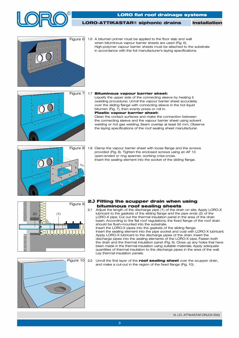
1.6 A bitumen primer must be applied to the floor slab and wall when bituminous vapour barrier sheets are used (Fig. 6). High-polymer vapour barrier sheets must be attached to the substrate in accordance with the foil manufacturer’s laying specifications.
1.7 Bituminous vapour barrier sheet: Liquefy the upper side of the connecting sleeve by heating it (welding procedure). Unroll the vapour barrier sheet accurately over the sliding flange with connecting sleeve in the hot liquid bitumen (Fig. 7), then evenly press or roll in. Plastic vapour barrier sheet: Clean the contact surfaces and make the connection between the connecting sleeve and the vapour barrier sheet using solvent welding or hot gas welding. Seam overlap at least 50 mm. Observe the laying specifications of the roof sealing sheet manufacturer.
Figure 7
Figure 6
Figure 8
Figure 92.) Fitting the scupper drain when using
bituminous roof sealing sheets
1.8 Clamp the vapour barrier sheet with loose flange and the screws provided (Fig. 8). Tighten the enclosed screws using an AF 13 open-ended or ring spanner, working criss-cross. Insert the sealing element into the socket of the sliding flange.
2.2 Unroll the first layer of the roof sealing sheet over the scupper drain, and make a cut-out in the region of the fixed flange (Fig. 10).
(1)(2)2.1 Adjust the length of the discharge pipe (1) of the drain on site. Apply LORO-X
lubricant to the gaskets of the sliding flange and the pipe ends (2) of the LORO-X pipe. Cut out the thermal insulation panel in the area of the drain basin. According to the flat roof regulations, the fixed flange of the roof drain should be flush-mounted into the substrate. Insert the LORO-X pipes into the gaskets of the sliding flange. Insert the sealing element into the pipe socket and coat with LORO-X lubricant. Apply LORO-X lubricant to the discharge pipes of the drain. Insert the discharge pipes into the sealing elements of the LORO-X pipe. Fasten both the drain and the thermal insulation panel (Fig. 9). Close up any holes that have been made in the thermal insulation using suitable materials. Apply adequate quantities of thermal insulation to the discharge pipes in the area of the wall. Lay thermal insulation panels.
4
VL LFL ATTIKASTAR DRUCK ENG
LORO flat roof drainage systems
Installation LORO-ATTIKASTAR® siphonic drains
Figure 15
Figure 12
Figure 11
Figure 13
Figure 14
Figure 15A
Figure 14A
Figure 13A
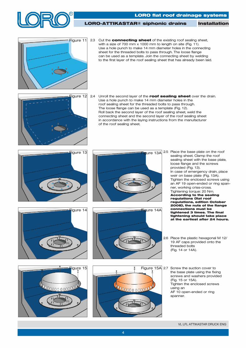
2.3 Cut the connecting sheet of the existing roof sealing sheet, with a size of 700 mm x 1000 mm to length on site (Fig. 11). Use a hole punch to make 14 mm diameter holes in the connecting sheet for the threaded bolts to pass through. The loose flange can be used as a template. Join the connecting sheet by welding to the first layer of the roof sealing sheet that has already been laid.
2.6 Place the plastic hexagonal M 12/ 19 AF caps provided onto the threaded bolts (Fig. 14 or 14A).
2.7 Screw the suction cover to the base plate using the fixing screws and washers provided (Fig. 15 or 15A). Tighten the enclosed screws using an AF 10 open-ended or ring spanner.
2.4 Unroll the second layer of the roof sealing sheet over the drain. Use a hole punch to make 14 mm diameter holes in the roof sealing sheet for the threaded bolts to pass through. The loose flange can be used as a template (Fig. 12). Roll back the second layer of the roof sealing sheet, weld the connecting sheet and the second layer of the roof sealing sheet in accordance with the laying instructions from the manufacturer of the roof sealing sheet.
2.5 Place the base plate on the roof sealing sheet. Clamp the roof sealing sheet with the base plate, loose flange and the screws provided (Fig. 13). In case of emergency drain, place weir on base plate (Fig. 13A). Tighten the enclosed screws using an AF 19 open-ended or ring span-ner, working criss-cross. Tightening torque: 20 Nm. According to the sealing regulations (flat roof regulations, edition October 2008), the nuts of the flange connections must be tightened 3 times. The final tightening should take place at the earliest after 24 hours.
5
VL LFL ATTIKASTAR DRUCK ENG
LORO flat roof drainage systems
Installation LORO-ATTIKASTAR® siphonic drains
Figure 12 Figure 12A
Figure 10
Figure 9
Figure 11
3.) Fitting the scupper drain with clamping flange when using plastic roof sealing sheets
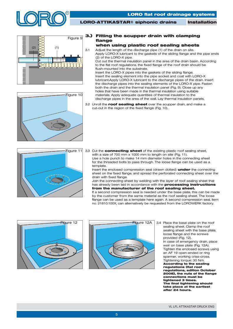
3.3 Cut the connecting sheet of the existing plastic roof sealing sheet, with a size of 700 mm x 1000 mm to length on site (Fig. 11). Use a hole punch to make 14 mm diameter holes in the connecting sheet for the threaded bolts to pass through. The loose flange can be used as a template. Insert the enclosed compression seal (drawn dotted) under the connecting sheet on the fixed flange, and spread the perforated connecting sheet over the drain with fixed flange. Join the connecting sheet by welding with the layer of roof sealing sheet that has already been laid in accordance with the processing instructions from the manufacturer of the roof sealing sheet. If a second compression seal is needed under the base plate, this can be made by the customer from the same material as the roof sealing sheet. The loose flange can be used as a template here again. A second compression seal, item no. 21810.100X, can alternatively be requested from the LOROWERK factory.
3.2 Unroll the roof sealing sheet over the scupper drain, and make a cut-out in the region of the fixed flange (Fig. 10).
3.4 Place the base plate on the roof sealing sheet. Clamp the roof sealing sheet with the base plate, loose flange and the screws provided (Fig. 12). In case of emergency drain, place weir on base plate (Fig. 12A). Tighten the enclosed screws using an AF 19 open-ended or ring spanner, working criss-cross. Tightening torque: 30 Nm. According to the sealing regulations (flat roof regulations, edition October 2008), the nuts of the flange connections must be tightened 3 times. The final tightening should take place at the earliest after 24 hours.
3.1 Adjust the length of the discharge pipe (1) of the drain on site. Apply LORO-X lubricant to the gaskets of the sliding flange and the pipe ends (2) of the LORO-X pipe. Cut out the thermal insulation panel in the area of the drain basin. According to the flat roof regulations, the fixed flange of the roof drain should be flush-mounted into the substrate. Insert the LORO-X pipes into the gaskets of the sliding flange. Insert the sealing element into the pipe socket and coat with LORO-X lubricant.Apply LORO-X lubricant to the discharge pipes of the drain. Insert the discharge pipes into the sealing elements of the LORO-X pipe. Fasten both the drain and the thermal insulation panel (Fig. 9). Close up any holes that have been made in the thermal insulation using suitable materials. Apply adequate quantities of thermal insulation to the discharge pipes in the area of the wall. Lay thermal insulation panels.
(1)(2)
6
VL LFL ATTIKASTAR DRUCK ENG
LORO flat roof drainage systems
Installation LORO-ATTIKASTAR® siphonic drains
LORO-X ATTIKASTAR® drains are to be serviced at 1/2 yearly intervals in accordance with DIN 1986, Part 30. Please also give these installation instructions to the plumber!
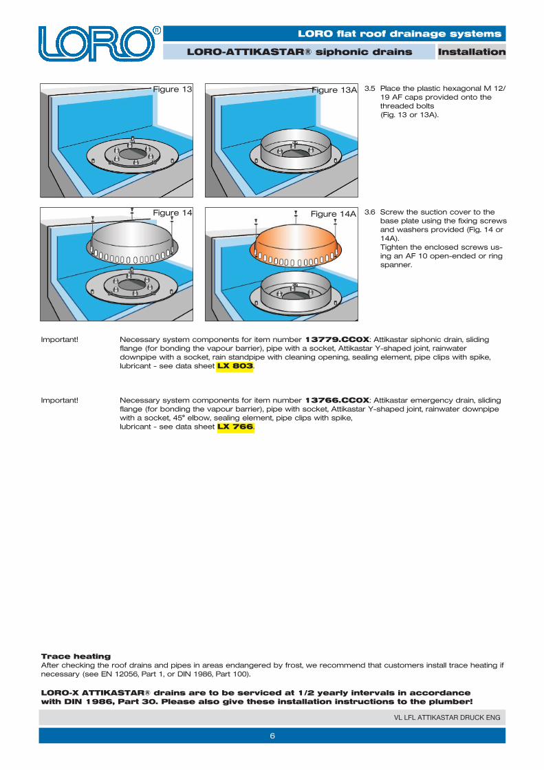
Important! Necessary system components for item number 13779.CC0X: Attikastar siphonic drain, sliding flange (for bonding the vapour barrier), pipe with a socket, Attikastar Y-shaped joint, rainwater downpipe with a socket, rain standpipe with cleaning opening, sealing element, pipe clips with spike, lubricant - see data sheet LX 803.
Important! Necessary system components for item number 13766.CC0X: Attikastar emergency drain, sliding flange (for bonding the vapour barrier), pipe with socket, Attikastar Y-shaped joint, rainwater downpipe with a socket, 45° elbow, sealing element, pipe clips with spike, lubricant - see data sheet LX 766.
3.5 Place the plastic hexagonal M 12/ 19 AF caps provided onto the threaded bolts (Fig. 13 or 13A).
3.6 Screw the suction cover to the base plate using the fixing screws and washers provided (Fig. 14 or 14A). Tighten the enclosed screws us-ing an AF 10 open-ended or ring spanner.
Trace heatingAfter checking the roof drains and pipes in areas endangered by frost, we recommend that customers install trace heating if necessary (see EN 12056, Part 1, or DIN 1986, Part 100).
Figure 14
Figure 13 Figure 13A
Figure 14A
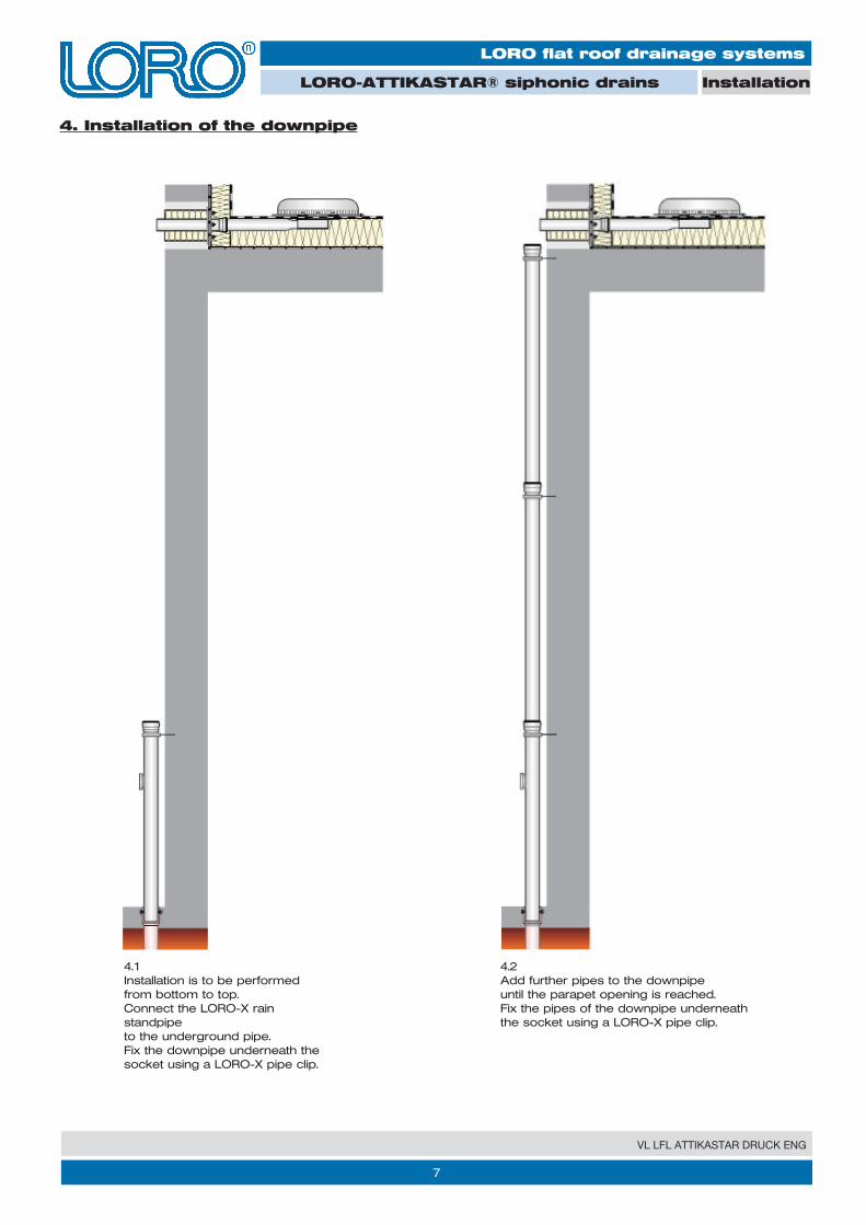
4. Installation of the downpipe
7
VL LFL ATTIKASTAR DRUCK ENG
4.1Installation is to be performed from bottom to top.Connect the LORO-X rain standpipe to the underground pipe.Fix the downpipe underneath the socket using a LORO-X pipe clip.
4.2Add further pipes to the downpipe until the parapet opening is reached.Fix the pipes of the downpipe underneath the socket using a LORO-X pipe clip.
LORO flat roof drainage systems
Installation LORO-ATTIKASTAR® siphonic drains
2/VL LFL ATTIKASTAR DRUCK ENG/1.0 8
VL LFL ATTIKASTAR DRUCK ENG
LORO flat roof drainage systems
Installation LORO-ATTIKASTAR® siphonic drains
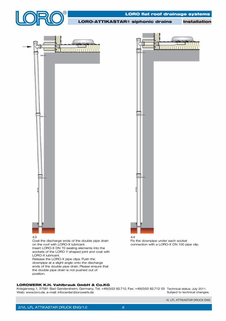
4.3Coat the discharge ends of the double pipe drain on the roof with LORO-X lubricant.Insert LORO-X DN 70 sealing elements into the sockets of the LORO Y-shaped joint and coat with LORO-X lubricant.Release the LORO-X pipe clips. Push the downpipe at a slight angle onto the discharge ends of the double pipe drain. Please ensure that the double pipe drain is not pushed out of position.
4.4Fix the downpipe under each socket connection with a LORO-X CN 100 pipe clip.
Technical status: July 2011.Subject to technical changes.
LOROWERK K.H. Vahlbrauk GmbH & Co.KGKriegerweg 1, 37581 Bad Gandersheim, Germany, Tel. +49(0)53 82.710, Fax: +49(0)53 82.712 03Web: www.loro.de, e-mail: [email protected]