Embed Size (px)
Citation preview
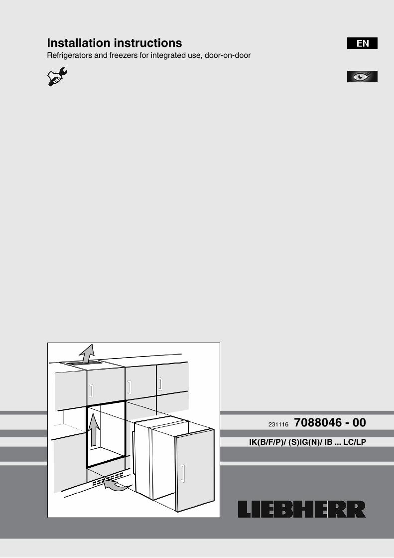
Installation instructionsRefrigerators and freezers for integrated use, door-on-door
231116 7088046 - 00IK(B/F/P)/ (S)IG(N)/ IB ... LC/LP
Contents1 General safety information................................... 22 Transporting the appliance................................... 23 Installing the appliance......................................... 24 Appliance dimensions........................................... 35 Recess dimensions............................................... 36 Unit door................................................................. 47 Ventilation of the kitchen unit............................... 58 Changing over door hinges.................................. 59 Water connection................................................... 610 Installing the appliance in the recess.................. 611 Disposing of packaging........................................ 712 Connecting the appliance..................................... 7
Illustrated installation instructions...................... 8
The manufacturer works constantly on the further developmentof all the types and models. Therefore please understand thatwe have to reserve the right to make design, equipment andtechnical modifications.To get to know all the benefits of your new appliance, pleaseread the information contained in these instructions carefully.The instructions apply to several models. Differences mayoccur. Text relating only to specific appliances is marked withan asterisk (*).Instructions for action are marked with a , the results ofaction are marked with a .
1 General safety information- Only install, connect and dispose of the appli-
ance according to the instructions. Takeparticular note of “Recess dimensions” (see 5)and “Ventilation of the kitchen unit” (see 7) .
- The socket must be easily accessible so thatthe appliance can be quickly disconnectedfrom the supply in an emergency. It must beoutside the area of the rear of the appliance.
DANGER identifies a situation involving directdanger which, if not obviated, mayresult in death or severe bodilyinjury.
WARNING identifies a dangerous situationwhich, if not obviated, may result indeath or severe bodily injury.
CAUTION identifies a dangerous situationwhich, if not obviated, may result inminor or medium bodily injury.
NOTICE identifies a dangerous situationwhich, if not obviated, may result indamage to property.
Note identifies useful information and tips.
2 Transporting the appliance
CAUTIONRisk of injury and danger of damage as a result of incorrecttransport!u Transport the appliance in a packed condition.u Transport the appliance upright.u Do not transport the appliance without assistance.
3 Installing the appliance
WARNINGRisk of fire due to short circuit!If the mains cable/connector of the appliance or of anotherappliance touch the rear of the appliance, the mains cable/connector may be damaged by the appliance vibrations,leading to a short circuit.u Stand the appliance so that it is not touched by connectors
or main cables.u Do not plug the appliance or any others into sockets located
near the rear of the appliance.
WARNINGFire hazard due to dampness!If live parts or the mains lead become damp this may causeshort circuits.u The appliance is designed for use in enclosed areas. Do not
operate the appliance outdoors or in areas where it isexposed to splash water or damp conditions.
u Only use the appliance when it is installed.
WARNINGFire hazard due to refrigerant!The refrigerant R 600a is environmentally friendly but flam-mable. Escaping refrigerant may ignite.u Do not damage the piping of the refrigeration circuit.
WARNINGFire hazard and danger of damage!u Do not place appliances emitting heat e.g. microwaves,
toasters etc. on the appliance!
Note*The bags at the rear of the appliance are important for properoperation. Their contents are nontoxic and nonhazardous.u Do not remove the bags!
NOTICERisk of damage due to condensation!When assembling an appliance name beginning with S... ora side-by-side (SBS) appliance:u The appliance can be installed next to another refrigerator or
freezer.If your appliance name does not begin with S...:u Do not install the appliance next to another refrigerator or
freezer.
General safety information
2 * Depending on model and options
NOTICERisk of damage due to condensation!When stacking multiple appliances there is a risk of conden-sation damage.Your IG.. or IB.. up to a height of 880 mm is fitted with an over-head heating system.u Do not stack refrigerators or freezers unless the bottom
appliance is your IG.. or IB.. model up to a height of 880 mm.
WARNINGBlocked ventilation openings pose a risk of fire and damage!u Always keep the ventilation openings clear. Always ensure
that the appliance is properly ventilated!
q In the event that the appliance is damaged, contact thesupplier immediately before connecting to the mains.
q The floor at the site must be flat and level.q Do not install the appliance in a location where it is exposed
to direct radiation of the sun, next to a cooker, heater andsimilar.
q Do not install the appliance alone: it is best to work togetherwith two or more people.
q The more R 600a refrigerant there is in the appliance, thelarger the room in which the appliance is standing needs tobe. In rooms that are too small, a flammable mix of gas andair may be created if there is a leak. According to the EN 378standard, every 11 g of R 600a refrigerant requires at least1 m3 space in the room for the appliance. The amount ofrefrigerant in your appliance is on the type plate inside theappliance.
q If the appliance is installed in a very damp environment,condensed water may form on the outside of the appliance.Always make sure that there is good ventilation - both at airinlet and outlet - at the site of installation.
If the transport lock is inserted on the door:u Pull off red transport lock.
If the transport lock is screwed onto the door:u Unscrew red transport lock.
Close the freed retaining holewith plugs (60).
After installation:u Remove protective films, adhesive tapes and transport lock
parts etc.Noteu Clean the appliance (see Operating Instructions,
Chapter "Cleaning the appliance").
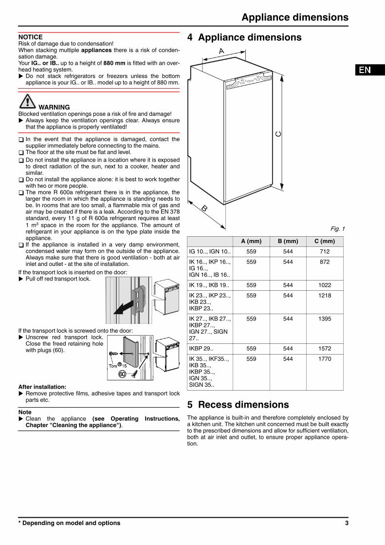
4 Appliance dimensions
Fig. 1 A (mm) B (mm) C (mm)
IG 10.., IGN 10.. 559 544 712IK 16.., IKP 16..,IG 16..,IGN 16.., IB 16..
559 544 872
IK 19.., IKB 19.. 559 544 1022IK 23.., IKP 23..,IKB 23..,IKBP 23..
559 544 1218
IK 27.., IKB 27..,IKBP 27..,IGN 27.., SIGN27..
559 544 1395
IKBP 29.. 559 544 1572IK 35.., IKF35..,IKB 35..,IKBP 35..,IGN 35..,SIGN 35..
559 544 1770
5 Recess dimensionsThe appliance is built-in and therefore completely enclosed bya kitchen unit. The kitchen unit concerned must be built exactlyto the prescribed dimensions and allow for sufficient ventilation,both at air inlet and outlet, to ensure proper appliance opera-tion.
Appliance dimensions
* Depending on model and options 3
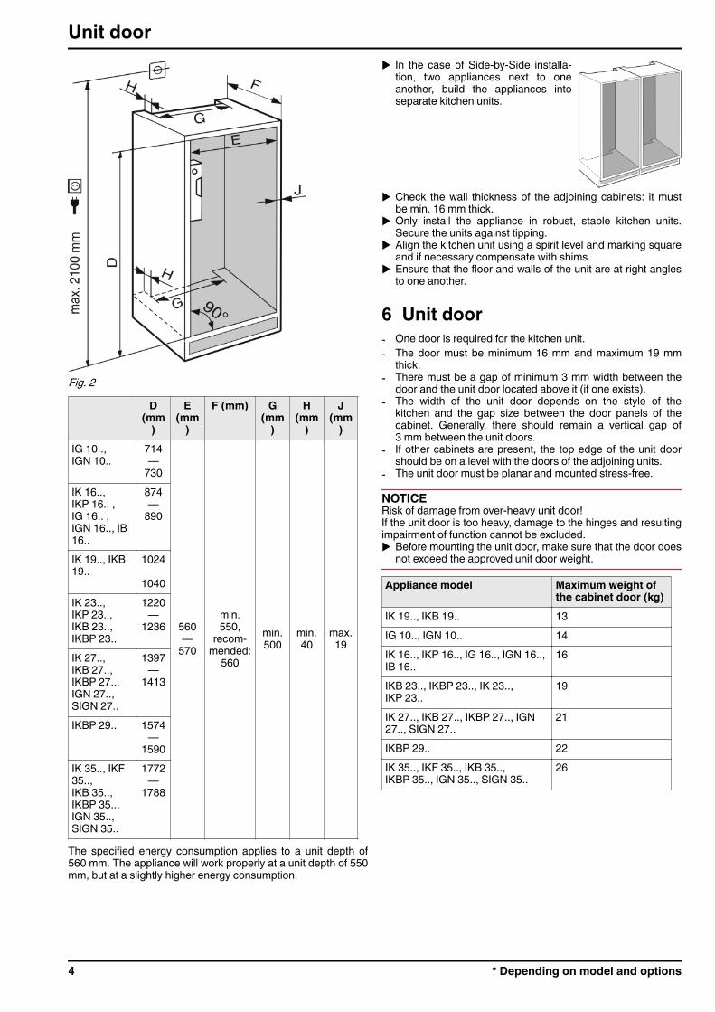
Fig. 2 D
(mm)
E(mm
)F (mm) G
(mm)
H(mm
)J
(mm)
IG 10..,IGN 10..
714—
730
560—
570
min.550,
recom-mended:
560
min.500
min.40
max.19
IK 16..,IKP 16.. ,IG 16.. ,IGN 16.., IB16..
874—
890
IK 19.., IKB19..
1024—
1040IK 23..,IKP 23..,IKB 23..,IKBP 23..
1220—
1236
IK 27..,IKB 27..,IKBP 27..,IGN 27..,SIGN 27..
1397—
1413
IKBP 29.. 1574—
1590IK 35.., IKF35..,IKB 35..,IKBP 35..,IGN 35..,SIGN 35..
1772—
1788
The specified energy consumption applies to a unit depth of560 mm. The appliance will work properly at a unit depth of 550mm, but at a slightly higher energy consumption.
u In the case of Side-by-Side installa-tion, two appliances next to oneanother, build the appliances intoseparate kitchen units.
u Check the wall thickness of the adjoining cabinets: it mustbe min. 16 mm thick.
u Only install the appliance in robust, stable kitchen units.Secure the units against tipping.
u Align the kitchen unit using a spirit level and marking squareand if necessary compensate with shims.
u Ensure that the floor and walls of the unit are at right anglesto one another.
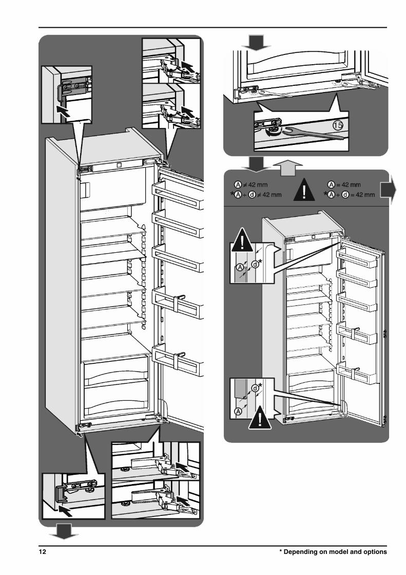
6 Unit door- One door is required for the kitchen unit.- The door must be minimum 16 mm and maximum 19 mm
thick.- There must be a gap of minimum 3 mm width between the
door and the unit door located above it (if one exists).- The width of the unit door depends on the style of the
kitchen and the gap size between the door panels of thecabinet. Generally, there should remain a vertical gap of3 mm between the unit doors.
- If other cabinets are present, the top edge of the unit doorshould be on a level with the doors of the adjoining units.
- The unit door must be planar and mounted stress-free.
NOTICERisk of damage from over-heavy unit door!If the unit door is too heavy, damage to the hinges and resultingimpairment of function cannot be excluded.u Before mounting the unit door, make sure that the door does
not exceed the approved unit door weight.
Appliance model Maximum weight ofthe cabinet door (kg)
IK 19.., IKB 19.. 13IG 10.., IGN 10.. 14IK 16.., IKP 16.., IG 16.., IGN 16..,IB 16..
16
IKB 23.., IKBP 23.., IK 23..,IKP 23..
19
IK 27.., IKB 27.., IKBP 27.., IGN27.., SIGN 27..
21
IKBP 29.. 22IK 35.., IKF 35.., IKB 35..,IKBP 35.., IGN 35.., SIGN 35..
26
Unit door
4 * Depending on model and options
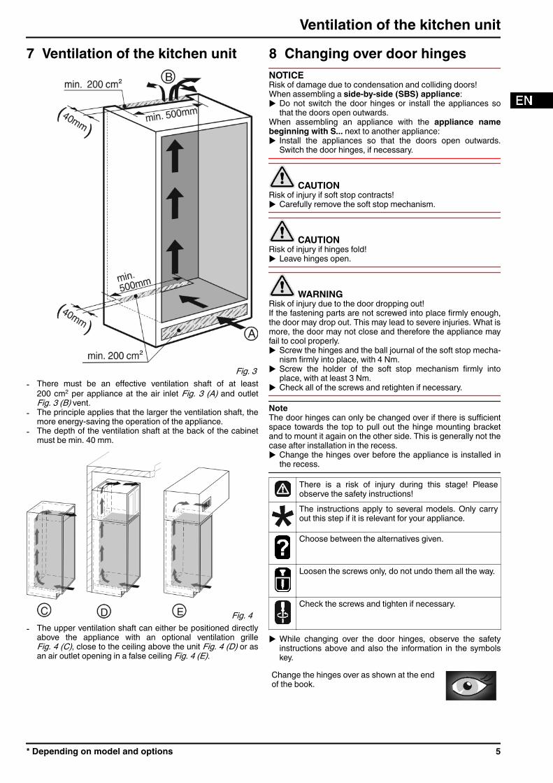
7 Ventilation of the kitchen unit
Fig. 3 - There must be an effective ventilation shaft of at least
200 cm2 per appliance at the air inlet Fig. 3 (A) and outletFig. 3 (B) vent.
- The principle applies that the larger the ventilation shaft, themore energy-saving the operation of the appliance.
- The depth of the ventilation shaft at the back of the cabinetmust be min. 40 mm.
Fig. 4 - The upper ventilation shaft can either be positioned directly
above the appliance with an optional ventilation grilleFig. 4 (C), close to the ceiling above the unit Fig. 4 (D) or asan air outlet opening in a false ceiling Fig. 4 (E).
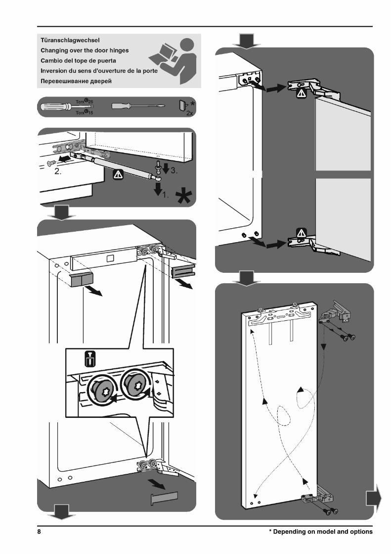
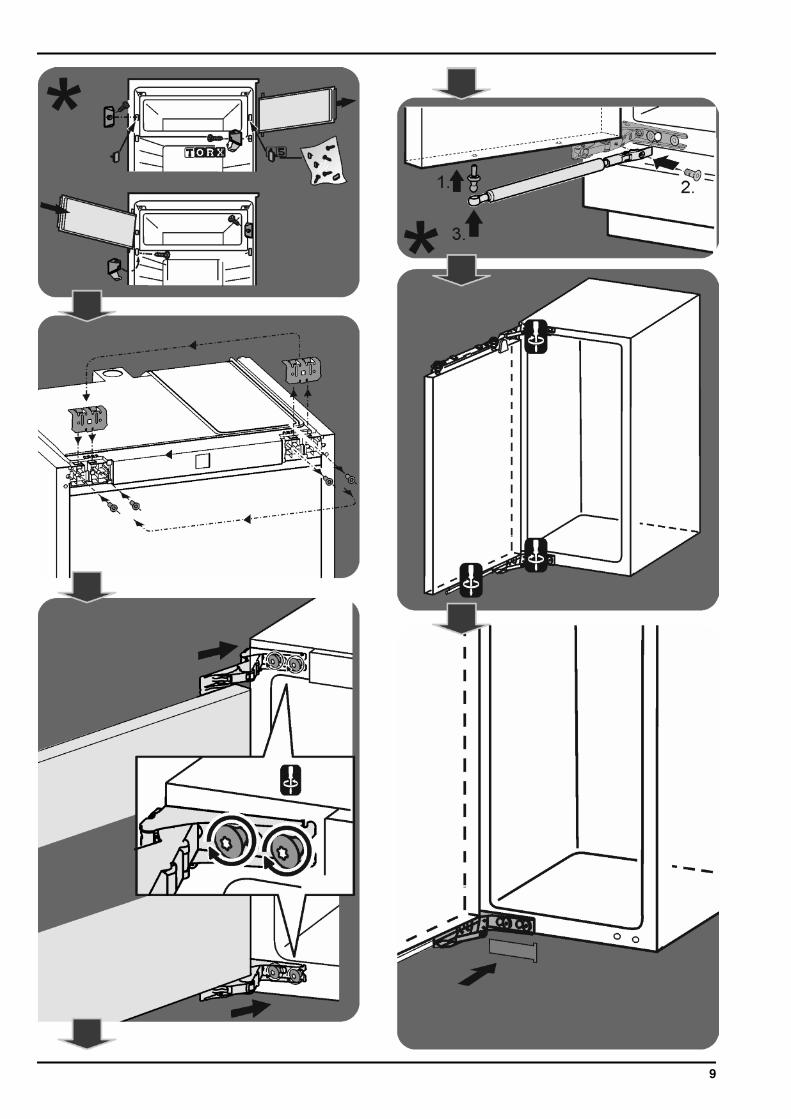
8 Changing over door hingesNOTICERisk of damage due to condensation and colliding doors!When assembling a side-by-side (SBS) appliance:u Do not switch the door hinges or install the appliances so
that the doors open outwards.When assembling an appliance with the appliance namebeginning with S... next to another appliance:u Install the appliances so that the doors open outwards.
Switch the door hinges, if necessary.
CAUTIONRisk of injury if soft stop contracts!u Carefully remove the soft stop mechanism.
CAUTIONRisk of injury if hinges fold!u Leave hinges open.
WARNINGRisk of injury due to the door dropping out!If the fastening parts are not screwed into place firmly enough,the door may drop out. This may lead to severe injuries. What ismore, the door may not close and therefore the appliance mayfail to cool properly.u Screw the hinges and the ball journal of the soft stop mecha-
nism firmly into place, with 4 Nm.u Screw the holder of the soft stop mechanism firmly into
place, with at least 3 Nm.u Check all of the screws and retighten if necessary.
NoteThe door hinges can only be changed over if there is sufficientspace towards the top to pull out the hinge mounting bracketand to mount it again on the other side. This is generally not thecase after installation in the recess.u Change the hinges over before the appliance is installed in
the recess.
There is a risk of injury during this stage! Pleaseobserve the safety instructions!The instructions apply to several models. Only carryout this step if it is relevant for your appliance.
Choose between the alternatives given.
Loosen the screws only, do not undo them all the way.
Check the screws and tighten if necessary.
u While changing over the door hinges, observe the safetyinstructions above and also the information in the symbolskey.
Change the hinges over as shown at the endof the book.
Ventilation of the kitchen unit
* Depending on model and options 5
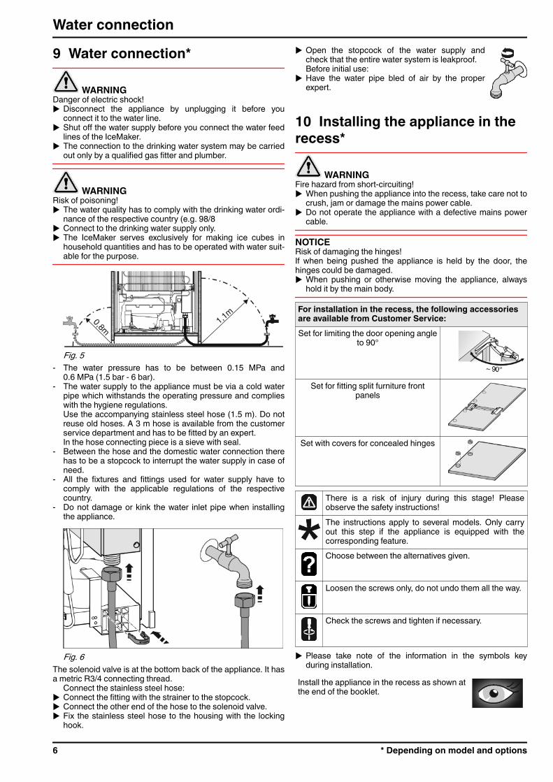
9 Water connection*
WARNINGDanger of electric shock!u Disconnect the appliance by unplugging it before you
connect it to the water line.u Shut off the water supply before you connect the water feed
lines of the IceMaker.u The connection to the drinking water system may be carried
out only by a qualified gas fitter and plumber.
WARNINGRisk of poisoning!u The water quality has to comply with the drinking water ordi-
nance of the respective country (e.g. 98/8u Connect to the drinking water supply only.u The IceMaker serves exclusively for making ice cubes in
household quantities and has to be operated with water suit-able for the purpose.
Fig. 5 - The water pressure has to be between 0.15 MPa and
0.6 MPa (1.5 bar - 6 bar).- The water supply to the appliance must be via a cold water
pipe which withstands the operating pressure and complieswith the hygiene regulations.Use the accompanying stainless steel hose (1.5 m). Do notreuse old hoses. A 3 m hose is available from the customerservice department and has to be fitted by an expert.In the hose connecting piece is a sieve with seal.
- Between the hose and the domestic water connection therehas to be a stopcock to interrupt the water supply in case ofneed.
- All the fixtures and fittings used for water supply have tocomply with the applicable regulations of the respectivecountry.
- Do not damage or kink the water inlet pipe when installingthe appliance.
Fig. 6 The solenoid valve is at the bottom back of the appliance. It hasa metric R3/4 connecting thread.
Connect the stainless steel hose:u Connect the fitting with the strainer to the stopcock.u Connect the other end of the hose to the solenoid valve.u Fix the stainless steel hose to the housing with the locking
hook.
u Open the stopcock of the water supply andcheck that the entire water system is leakproof.Before initial use:
u Have the water pipe bled of air by the properexpert.
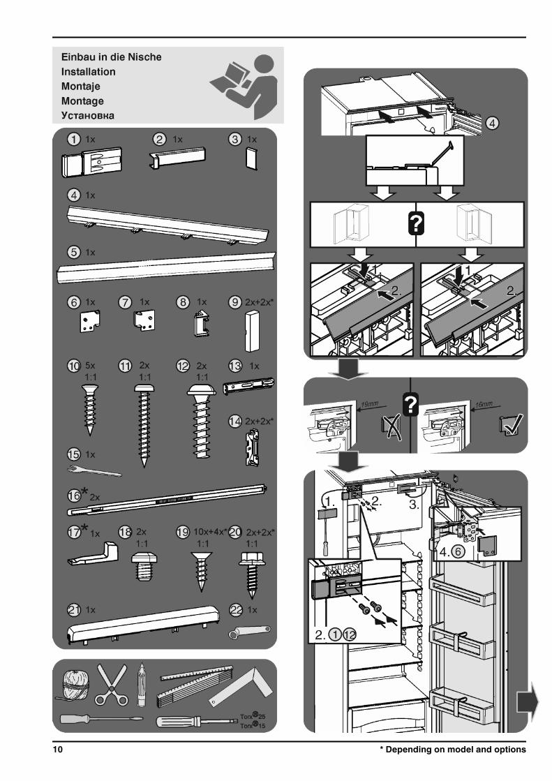
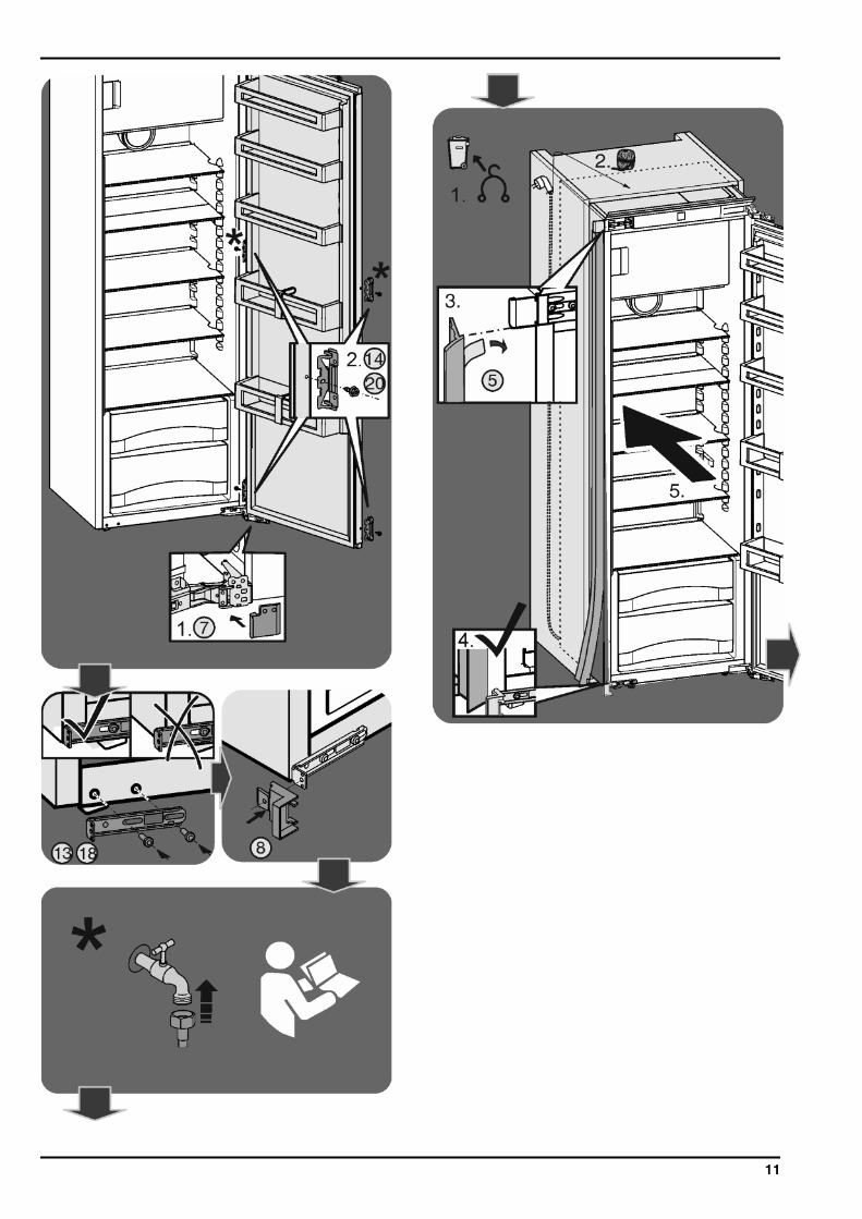
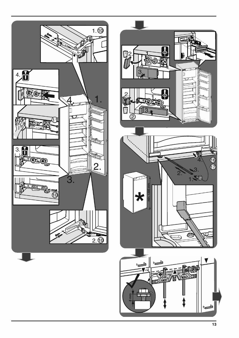
10 Installing the appliance in therecess*
WARNINGFire hazard from short-circuiting!u When pushing the appliance into the recess, take care not to
crush, jam or damage the mains power cable.u Do not operate the appliance with a defective mains power
cable.
NOTICERisk of damaging the hinges!If when being pushed the appliance is held by the door, thehinges could be damaged.u When pushing or otherwise moving the appliance, always
hold it by the main body.
For installation in the recess, the following accessoriesare available from Customer Service:Set for limiting the door opening angle
to 90°
Set for fitting split furniture frontpanels
Set with covers for concealed hinges
There is a risk of injury during this stage! Pleaseobserve the safety instructions!The instructions apply to several models. Only carryout this step if the appliance is equipped with thecorresponding feature.Choose between the alternatives given.
Loosen the screws only, do not undo them all the way.
Check the screws and tighten if necessary.
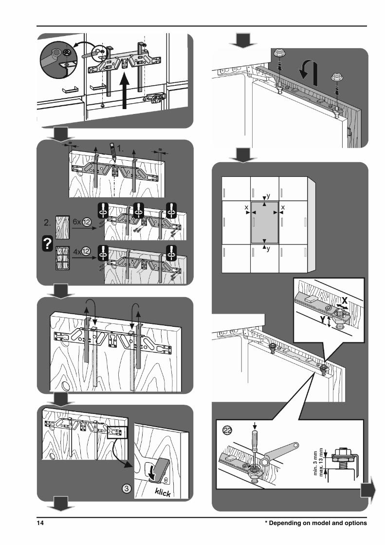
u Please take note of the information in the symbols keyduring installation.
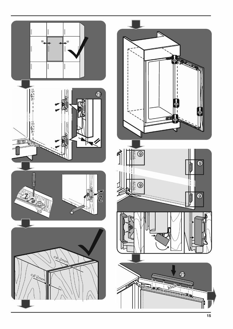
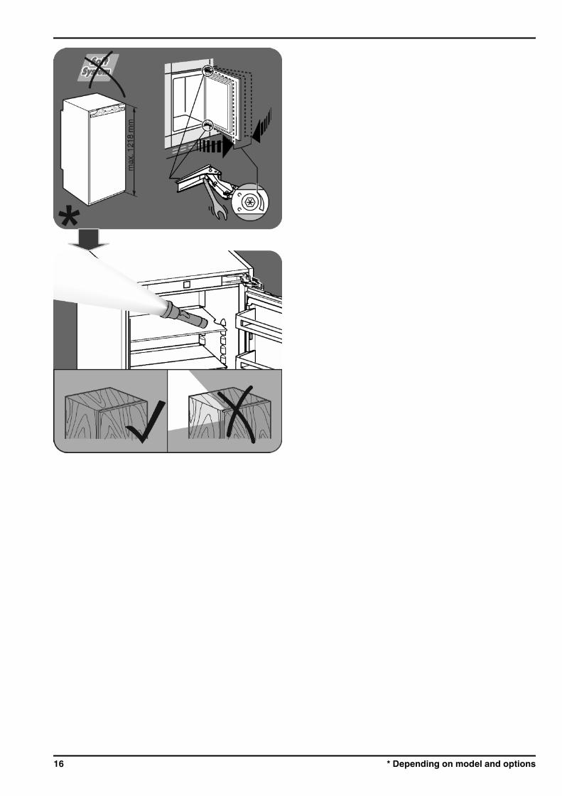
Install the appliance in the recess as shown atthe end of the booklet.
Water connection
6 * Depending on model and options

Installation film
11 Disposing of packaging
WARNINGDanger of suffocation due to packing material and plastic film!u Do not allow children to play with packing material.The packaging is made of recyclable materials:- corrugated board/cardboard- expanded polystyrene parts- polythene bags and sheets- polypropylene straps- nailed wooden frame with polyethylene panel*u Take the packaging material to an official collecting point.
12 Connecting the applianceNOTICEFailure to connect properlyDamage to the electronics.u Do not use a standalone inverter.u Do not use an energy saving plug.
WARNINGFailure to connect properlyFire.u Do not use an extension cable.u Do not use distributor blocks.The type of current (alternating current) and voltage at theinstallation site have to conform with the data on the type plate(see Appliance at a glance).The socket must be properly earthed and fused. The trippingcurrent for the fuse must be between 10 A and 16 A.The socket must be easily accessible so that the appliance canbe quickly disconnected from the supply in an emergency. Itmust be outside the area of the rear of the appliance.u Check the electrical connection.u Plug in the power plug.
Disposing of packaging
* Depending on model and options 7
8 * Depending on model and options
9
10 * Depending on model and options
11
12 * Depending on model and options
13
14 * Depending on model and options
15
16 * Depending on model and options

17
Liebherr-Hausgeräte Ochsenhausen GmbHMemminger Straße 77-7988416 OchsenhausenDeutschlandhome.liebherr.com