Embed Size (px)
Citation preview
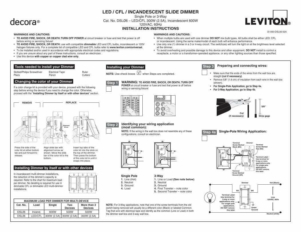
Identifying your wiring application (most common):NOTE: If the wiring in the wall box does not resemble any of these configurations, consult an electrician.
LED / CFL / INCANDESCENT SLIDE DIMMER Single Pole or 3-Way
Cat. No. DSLØ6 – LED/CFL 300W (2.5A), Incandescent 600W120VAC, 60Hz
INSTALLATION INSTRUCTIONS
Tools needed to install your DimmerSlotted/Philips Screwdriver Electrical Tape Ruler Pliers Pencil Cutters
LOC
OFF
ON
A B
LOC
OFF
ON
A B
SlideBar
AlignmentArrow
Step 3
Changing the color of your Dimmer
If a color change kit is provided with your device, proceed with the following step before wiring the device if you need to change the color. Otherwise, proceed with the "Installing Dimmer by itself or with other devices" section.
In incandescent multi-dimmer installations, the reduction of the dimmer’s capacity is required. Refer to the chart for maximum load per dimmer. No derating is required for use in dimmable CFL or dimmable LED multi-dimmer installations.
Installing Dimmer by itself or with other devices
Step 2
ONOFF
ONOFF
ONOFF
ONOFF
ONOFF
ONOFF
ONOFFONOFF
ONOFF
ONOFF
ONOFF
ONOFF
WARNING: TO AVOID FIRE, SHOCK, OR DEATH; TURN OFF POWER at circuit breaker or fuse and test that power is off before wiring or servicing fixture!
Step 1
Single Pole1. Line (Hot)2. Neutral 3. Ground4. Load
NOTE: For 3-Way applications, note that one of the screw terminals from the old switch being removed will usually be a different color (Black) or labeled Common. Tag that wire with electrical tape and identify as the common (Line or Load) in both the dimmer wall box and 3-way wall box.
Preparing and connecting wires:
Strip gageCut
(if necessary)
5/8"
• Make sure that the ends of the wires from the wall box are straight (cut if necessary).
• Remove 5/8" (1.6 cm) of insulation from each wire in the wall box (shown).
• For Single-Pole Application, go to Step 4a.• For 3-Way Application, go to Step 4b.
Single-Pole Wiring Application:Step 4a
3-Way1. Line or Load (See note below)2. Neutral3. Ground4. First Traveler – note color5. Second Traveler – note color
DI-000-DSL06-02A
Installing your Dimmer
NOTE: Use check boxes when Steps are completed.√
3
2
4
1
5
3
2 1
4
Terminal Screw Marked Black (BK)
Terminal Screw Marked Red (RD)
Terminal Label:Use terminal for 3-way or more applications only. For single pole applications, DO NOT remove this label.
3
2 1
4
Dimmer
Terminal Screw Marked Ground (GR)
Terminal Label:Use terminal for
3-way or more applications only.
For single pole applications,
DO NOT remove this label.
Green Ground
BKRD
Hot (Black)
Neutral (white)
Line120VAC, 60Hz
Dimmer
Insert top tabs of the color kit into the slots on the top of the dimmer. Then press the bottom of the color kit in until it snaps into place.
Press the side of the color kit at either bottom tab and pull forward to release.
Align slide bar with alignment arrow as shown. Move the slide bar of the color kit to the bottom.
REMOVE REPLACE
MAXIMUM LOAD PER DIMMER FOR MULTI-DEVICE
Cat. No. Load Single Two Devices
More than 2 Devices
DSLØ6 Incand. 600W 500W 500W
DSLØ6 LED/CFL 300W (2.5A) 300W (2.5A) 300W (2.5A)
WARNINGS AND CAUTIONS:• When multiple bulbs are used with one dimmer DO NOT mix bulb types. All bulbs shall be either LED; CFL
or incandescent. Using the same make/model of each bulb will enhance performance.• Use only one (1) dimmer in a 3 or 4-way circuit. The switch(es) will turn the light on at the brightness level selected
at the dimmer.• To avoid overheating and possible damage to this device and other equipment, DO NOT install to control a
receptacle, a motor or a transformer-operated appliance, or any other lighting sources than those specified.
WARNINGS AND CAUTIONS:• TO AVOID FIRE, SHOCK, OR DEATH: TURN OFF POWER at circuit breaker or fuse and test that power is off
before wiring or servicing fixture!• TO AVOID FIRE, SHOCK, OR DEATH: use with compatible dimmable LED and CFL bulbs, incandescent or 120V
halogen fixtures only. For a complete list of compatible LED and CFL bulbs refer to www.leviton.com/universal.• To be installed and/or used in accordance with appropriate electrical codes and regulations.• If you are unsure about any part of these instructions, consult an electrician.• Use this device with copper or copper clad wire only.
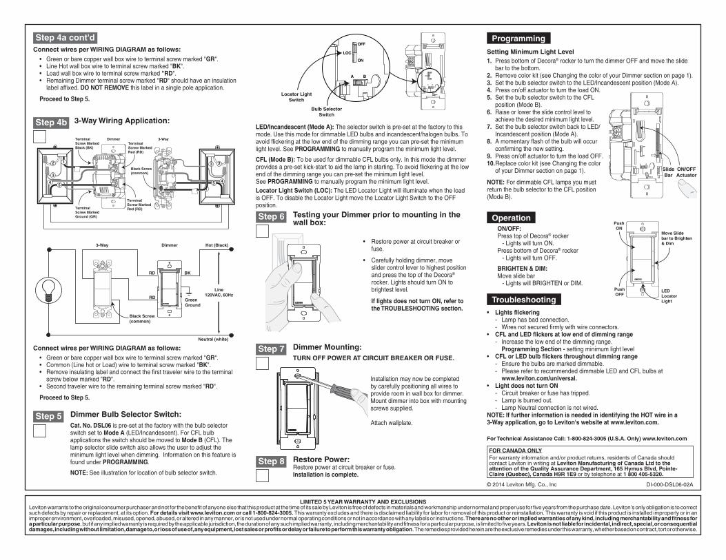
Restore Power: Restore power at circuit breaker or fuse. Installation is complete.
Step 8
For Technical Assistance Call: 1-800-824-3005 (U.S.A. Only) www.leviton.com
• Lights flickering - Lamp has bad connection. - Wires not secured firmly with wire connectors.• CFL and LED flickers at low end of dimming range
- Increase the low end of the dimming range. Programming Section - setting minimum light level
• CFL or LED bulb flickers throughout dimming range - Ensure the bulbs are marked dimmable. - Please refer to recommended dimmable LED and CFL bulbs at
www.leviton.com/universal.• Light does not turn ON - Circuit breaker or fuse has tripped. - Lamp is burned out. - Lamp Neutral connection is not wired.NOTE: If further information is needed in identifying the HOT wire in a 3-Way application, go to Leviton's website at www.leviton.com.
Step 4a cont'd
• Green or bare copper wall box wire to terminal screw marked "GR".• Line Hot wall box wire to terminal screw marked "BK".• Load wall box wire to terminal screw marked "RD".• Remaining Dimmer terminal screw marked "RD" should have an insulation
label affixed. DO NOT REMOVE this label in a single pole application.
Proceed to Step 5.
3-Way Wiring Application:Step 4b
Dimmer Mounting:TURN OFF POWER AT CIRCUIT BREAKER OR FUSE.
Step 7
Installation may now be completed by carefully positioning all wires to provide room in wall box for dimmer. Mount dimmer into box with mounting screws supplied.
Attach wallplate.
ON/OFF: Press top of Decora® rocker - Lights will turn ON.Press bottom of Decora® rocker - Lights will turn OFF.
BRIGHTEN & DIM: Move slide bar - Lights will BRIGHTEN or DIM.
• Restore power at circuit breaker or fuse.
• Carefully holding dimmer, move slider control lever to highest position and press the top of the Decora® rocker. Lights should turn ON to brightest level.
If lights does not turn ON, refer to the TROUBLESHOOTING section.
Testing your Dimmer prior to mounting in the wall box:
Step 6
Step 5 Dimmer Bulb Selector Switch:Cat. No. DSL06 is pre-set at the factory with the bulb selector switch set to Mode A (LED/Incandescent). For CFL bulb applications the switch should be moved to Mode B (CFL). The lamp selector slide switch also allows the user to adjust the minimum light level when dimming. Information on this feature is found under PROGRAMMING.
NOTE: See illustration for location of bulb selector switch.
Setting Minimum Light Level1. Press bottom of Decora® rocker to turn the dimmer OFF and move the slide
bar to the bottom.2. Remove color kit (see Changing the color of your Dimmer section on page 1).3. Set the bulb selector switch to the LED/Incandescent position (Mode A).4. Press on/off actuator to turn the load ON.5. Set the bulb selector switch to the CFL
position (Mode B).6. Raise or lower the slide control level to
achieve the desired minimum light level.7. Set the bulb selector switch back to LED/
Incandescent position (Mode A).8. A momentary flash of the bulb will occur
confirming the new setting.9. Press on/off actuator to turn the load OFF.10. Replace color kit (see Changing the color
of your Dimmer section on page 1).
NOTE: For dimmable CFL lamps you must return the bulb selector to the CFL position (Mode B).
LED/Incandescent (Mode A): The selector switch is pre-set at the factory to this mode. Use this mode for dimmable LED bulbs and incandescent/halogen bulbs. To avoid flickering at the low end of the dimming range you can pre-set the minimum light level. See PROGRAMMING to manually program the minimum light level.
CFL (Mode B): To be used for dimmable CFL bulbs only. In this mode the dimmer provides a pre-set kick-start to aid the lamp in starting. To avoid flickering at the low end of the dimming range you can pre-set the minimum light level. See PROGRAMMING to manually program the minimum light level.Locator Light Switch (LOC): The LED Locator Light will illuminate when the load is OFF. To disable the Locator Light move the Locator Light Switch to the OFF position.
DI-000-DSL06-02A
LIMITED 5 YEAR WARRANTY AND EXCLUSIONSLeviton warrants to the original consumer purchaser and not for the benefit of anyone else that this product at the time of its sale by Leviton is free of defects in materials and workmanship under normal and proper use for five years from the purchase date. Leviton’s only obligation is to correct such defects by repair or replacement, at its option. For details visit www.leviton.com or call 1-800-824-3005. This warranty excludes and there is disclaimed liability for labor for removal of this product or reinstallation. This warranty is void if this product is installed improperly or in an improper environment, overloaded, misused, opened, abused, or altered in any manner, or is not used under normal operating conditions or not in accordance with any labels or instructions. There are no other or implied warranties of any kind, including merchantability and fitness for a particular purpose, but if any implied warranty is required by the applicable jurisdiction, the duration of any such implied warranty, including merchantability and fitness for a particular purpose, is limited to five years. Leviton is not liable for incidental, indirect, special, or consequential damages, including without limitation, damage to, or loss of use of, any equipment, lost sales or profits or delay or failure to perform this warranty obligation. The remedies provided herein are the exclusive remedies under this warranty, whether based on contract, tort or otherwise.
FOR CANADA ONLYFor warranty information and/or product returns, residents of Canada should contact Leviton in writing at Leviton Manufacturing of Canada Ltd to the attention of the Quality Assurance Department, 165 Hymus Blvd, Pointe-Claire (Quebec), Canada H9R 1E9 or by telephone at 1 800 405-5320.
3
2
4
1 23
4
155
Terminal Screw Marked Black (BK)
Terminal Screw Marked Red (RD)
Black Screw(common)
Terminal Screw Marked Red (RD)
Dimmer 3-Way
Terminal Screw Marked Ground (GR)
Green Ground
BKRD
Hot (Black)
Neutral (white)
Line120VAC, 60HzRD
Black Screw(common)
3-Way Dimmer
Move Slide bar to Brighten & Dim
PushON
PushOFF
LED Locator Light
Bulb SelectorSwitch
Locator LightSwitch
OFF
ON
LOC
A B LOC
A B
Connect wires per WIRING DIAGRAM as follows:
• Green or bare copper wall box wire to terminal screw marked "GR".• Common (Line hot or Load) wire to terminal screw marked "BK".• Remove insulating label and connect the first traveler wire to the terminal
screw below marked "RD".• Second traveler wire to the remaining terminal screw marked "RD".
Proceed to Step 5.
Connect wires per WIRING DIAGRAM as follows:
ON/OFFActuator
LOC
A B
SlideBar
OFF
ON
© 2014 Leviton Mfg. Co., Inc
Troubleshooting
Operation
Programming