Embed Size (px)
Citation preview

KIT# 1559-102/06/13
KSR
O
A
D
M
A
S
T
E
R,
I
N
C.
ROADMASTER, Inc. 6110 NE 127th Ave. Vancouver, WA 98682 360-896-0407 fax 360-735-9300 www.roadmasterinc.com
BASEPLATE KIT INSTALLATION INSTRUCTIONS
1
2
3
4
56
7
8
9
10
11
13
14
15
12
ITEM QTY NAME MATERIAL1...........8...........8mm x 1.25 x 30mm BOLT .....................................................356001-002...........8...........8mm LOCK WASHER ............................................................355705-003...........8...........5/16” FLAT WASHER .............................................................350303-204...........2...........1/2” x 3 1/2” BOLT ..................................................................350103-005...........2...........1/2” x 1 1/2” BOLT ..................................................................350095-006...........4...........1/2” LOCK WASHER ..............................................................350309-007...........2...........1/2” NUT .................................................................................350258-008...........2...........1/2” PLATE WASHER ............................................................A-0030869...........2...........DRAW PIN/SPRING PIN ........................................................357035-0010.........2...........CABLE CONNECTOR ...........................................................200008-0011 .........2...........8” SAFETY CABLE.................................................................650646-0812.........2...........1 3/4” x 3” BACKING PLATE ..................................................A-00231713.........1...........MAIN RECEIVER BRACE WELDMENT ................................C-00144514.........1...........DRIVER SIDE ARM WELDMENT ..........................................C-00144615.........1...........PASSENGER SIDE ARM WELDMENT .................................C-00144716.........4...........ZIP TIES .................................................................................300140-8

KIT# 1559-102/06/13
KS
Fig.A
Fig.B
This bracket kit is one of our XL series, which allows the visible front portion of the brack-ets to be easily removed (Fig.A and Fig.B).
The kit consists of the main receiver braces, re-movable front braces, rear braces, backing plate weldments and a hardware pack.
The main receiver brace mounts to the front frame and bumper core on each side. The remov-able front braces insert into the receivers on each side and are secured with draw pins.
Before starting the installation, lay out the kit components in order, as they will be used. This will give you a visual idea of how the components work, and will also confirm that everything is present and accounted for.
IMPORTANT: All brackets must be assembled with all the bolts left loose for final adjustment and positioning (before tightening) unless otherwise instructed. All bolts must be torqued for proper strength. If more than one bolt is used per fastening point, the diagram may only show one.
• Use flat washers over all slotted holes • Use lock washers on all fasteners
• Installation of most mounting brackets requires moderate mechani-cal aptitude and skills. We strongly recommend professional installa-tion by an experienced installer.
• The installer must read the instructions and use all bolts and partssupplied. Failure to do so could result in loss of the towed vehicle.
• Use Loctite® Red on all bolts used for mounting this bracket.
• Every 3,000 miles, the owner must inspect the fasteners for propertorque, according to the bolt torque requirements chart on the last pageof these instructions. The owner must also inspect all mounts andbrackets for cracks or other signs of fatigue every 3,000 miles.Failure to do so could result in loss of the towed vehicle.
• The owner must check the vehicle manufacturer's instructions forthe proper procedure(s) to prepare the vehicle for towing. Somevehicles must be equipped with a transmission lube pump, an axle dis-connect, driveline disconnect or free-wheeling hubs before they can betowed. Failure to properly equip the vehicle will cause severe damageto the transmission.
• If running changes were made by the vehicle manufacturer after thisbracket was designed, some bolts or other fasteners in the hardwarepack may no longer be the correct size. It is the installer’s responsi-bility to verify that the bracket is securely fastened to the vehicle andfitted with the correct hardware to account for these changes. Failure tosecurely fasten the bracket could result in loss of the towed vehicle.
• If the towed vehicle has been in an accident, it must be properly re-paired before attaching the bracket. Do not install the bracket if anystructural frame damage is found. Failure to repair the damage couldresult in the loss of the towed vehicle.
• Roadmaster manufactures many styles of brackets. If your brackethas removable arms, they must be removed before driving thevehicle, unless the arms can be pinned or padlocked in place.If not secured, the arms could vibrate out, resulting in non-warrantydamage or personal injury.
• Some motorhome chassis have such a tight turning radius that you candamage your motorhome, towed vehicle, tow bar or bracket while turningsharply. Before getting on the road, test your turning radius in anempty parking lot. Turning too sharply could result in non-warrantydamage to towing system, motorhome and/or towed vehicle.
• Do not back up with the towed vehicle attached or non-warrantydamage will occur to your towing system, motorhome and/or towedvehicle.
• The safety cables must connect the towing vehicle to the towedvehicle frame to frame, with the cables crossed, with enough slackfor sharp turns. Refer to the cable instructions for proper routing.Failure to leave enough slack in the safety cables, or failure to connectthe safety cables frame to frame, will result in the loss of the towedvehicle.
• This bracket is designed for use with ROADMASTER tow bars andROADMASTER adaptors only. Using this bracket with other brands,without an approved ROADMASTER adaptor, may result in non-warranty damage or injury.
• Do not use this document for custom fabrication, as it may not showall parts or structural components. Custom fabrication or an attempt tocopy this bracket design could result in loss of the towed vehicle.
• Upon final installation, the installer must inspect the bracket to en-sure adequate clearance, particularly around hoses, air conditionerlines, radiators, etc., or non-warranty damage to the towed vehiclewill result.
• This bracket is only warranteed for the original installation. Installinga used bracket on another vehicle is not recommended and will voidthe warranty.
Failure to follow these instructions can result in property damage, personal injury or even death.WARNING
BASEPLATE KIT INSTALLATION INSTRUCTIONS
ROADMASTER, Inc. 6110 NE 127th Ave. Vancouver, WA 98682 360-896-0407 fax 360-735-9300 www.roadmasterinc.com

KIT# 1559-102/06/13
KS
All illustrations and specifications contained herein are based on the latest information available at the time of publication approval. ROADMASTER, INC. reserves the right to make changes at any time without notice in material, specification and models or to discontinue models.
1. Important: please use all supplied bolts and parts and read all instructions carefully before beginning thisinstallation. The majority of questions you may have can be answered within the text, and proper installation will ensure safe and secure travel. Now, begin the installation by removing seven plastic fasteners attaching the radiator cover to the core support (Fig.C).
2. On both sides, remove two screws and one plastic fastener attaching the fender liner to the fascia (Fig.D).
3. Next, on each side, remove one 10mm screw attaching the fender liner to the fascia (Fig.E).
4. Remove four plastic fasteners attaching the splashshield to the fascia (Fig.F).
5. Now, remove the fascia by pulling out and forwardon both corners (Fig.G). Disconnect the fog lights, if your vehicle is so equipped.
Fig.C Fig.D
Fig.E Fig.F
Fig.G
BASEPLATE KIT INSTALLATION INSTRUCTIONS
ROADMASTER, Inc. 6110 NE 127th Ave. Vancouver, WA 98682 360-896-0407 fax 360-735-9300 www.roadmasterinc.com
KIT# 1559-102/06/13
KS
All illustrations and specifications contained herein are based on the latest information available at the time of publication approval. ROADMASTER, INC. reserves the right to make changes at any time without notice in material, specification and models or to discontinue models.
6. Remove the air temperature sensor and wiring harness from the bumper core by removing four plastic fasteners, ifthe vehicle is so equipped (Fig.H).
7. On each side, remove three 12mm bolts attaching the bumper core to the frame rail (Fig.I). The bumper core willnot be replaced. Note: retain the bumper core and attachment hardware so that it can be replaced if the bracket is ever removed.
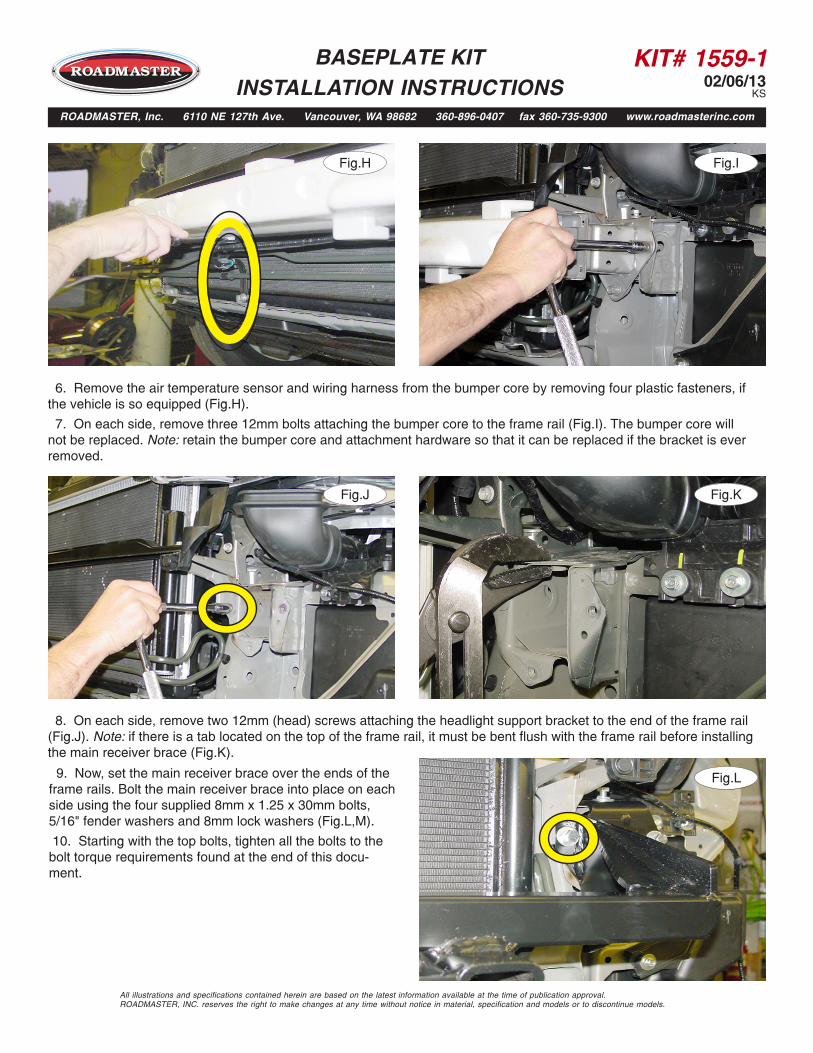
8. On each side, remove two 12mm (head) screws attaching the headlight support bracket to the end of the frame rail(Fig.J). Note: if there is a tab located on the top of the frame rail, it must be bent flush with the frame rail before installing the main receiver brace (Fig.K).
9. Now, set the main receiver brace over the ends of theframe rails. Bolt the main receiver brace into place on each side using the four supplied 8mm x 1.25 x 30mm bolts, 5/16" fender washers and 8mm lock washers (Fig.L,M).
10. Starting with the top bolts, tighten all the bolts to thebolt torque requirements found at the end of this docu-ment.
Fig.H Fig.I
Fig.J Fig.K
Fig.L
BASEPLATE KIT INSTALLATION INSTRUCTIONS
ROADMASTER, Inc. 6110 NE 127th Ave. Vancouver, WA 98682 360-896-0407 fax 360-735-9300 www.roadmasterinc.com

KIT# 1559-102/06/13
KS
All illustrations and specifications contained herein are based on the latest information available at the time of publication approval. ROADMASTER, INC. reserves the right to make changes at any time without notice in material, specification and models or to discontinue models.
11. Working on one side at a time, use the supplied ½" x 1½" bolt, lock washer and plate washer and bolt through themain receiver brace and into the existing hole in the side of the frame rail (Fig.N). Repeat for the other side.
12. The air box and the power steering cooling line need to be temporarily moved to allow room to drill the holes in thecore support. Start by removing two 10mm (head) screws from the air box, then pull straight down to remove it (Fig.O).
Next, remove one 10mm screw attaching the power steering cooling line to the core support (Fig.P). Now, pull the power steering cooling line back and out of the way in the direction indicated in Figure Q.
Fig.M Fig.N
Fig.O Fig.P
Fig.Q
BASEPLATE KIT INSTALLATION INSTRUCTIONS
ROADMASTER, Inc. 6110 NE 127th Ave. Vancouver, WA 98682 360-896-0407 fax 360-735-9300 www.roadmasterinc.com
powersteering cooling
line

KIT# 1559-102/06/13
KS
13. Remove the plastic fastener attaching the wiring harness to the inside of the core support on the driver's side. Now,on each side, using the pre-drilled hole in the main receiver brace as a template, drill through the existing hole in theoutside of the core support and through the back side of the core support (Fig.R). Note: before drilling, make certain youwill not drill into any engine components on the other side.
14. On each side, attach the main receiver brace to the core support using a ½" x 3½" bolt, 3/16" x 1¾" x 3" backingplate, lock washer and locknut (Fig.S). Torque the bolts to 45 ft./lbs and the nut to 35 ft./lbs.
15. Tighten all the remaining bolts to the bolt torque requirements found at the end of these instructions.
16. Reattach the air box and the power steering cooling line, reversing steps 12 and 13. Note: due to manufacturingvariances, the power steering cooling line may contact the main receiver brace on the passenger side of the vehicle. If thisis the case, bend the power steering cooling line slightly to get at least a ½" of clearance between the line and the mainreceiver brace (Fig.T).
17. Now, reattach the air temperature sensor to the back of the main receiver brace using the four supplied zip ties(Fig.U).
All illustrations and specifications contained herein are based on the latest information available at the time of publication approval. ROADMASTER, INC. reserves the right to make changes at any time without notice in material, specification and models or to discontinue models.
Fig.R Fig.S
Fig.T Fig.U
BASEPLATE KIT INSTALLATION INSTRUCTIONS
ROADMASTER, Inc. 6110 NE 127th Ave. Vancouver, WA 98682 360-896-0407 fax 360-735-9300 www.roadmasterinc.com
Checkforclearance
KIT# 1559-102/06/13
KS
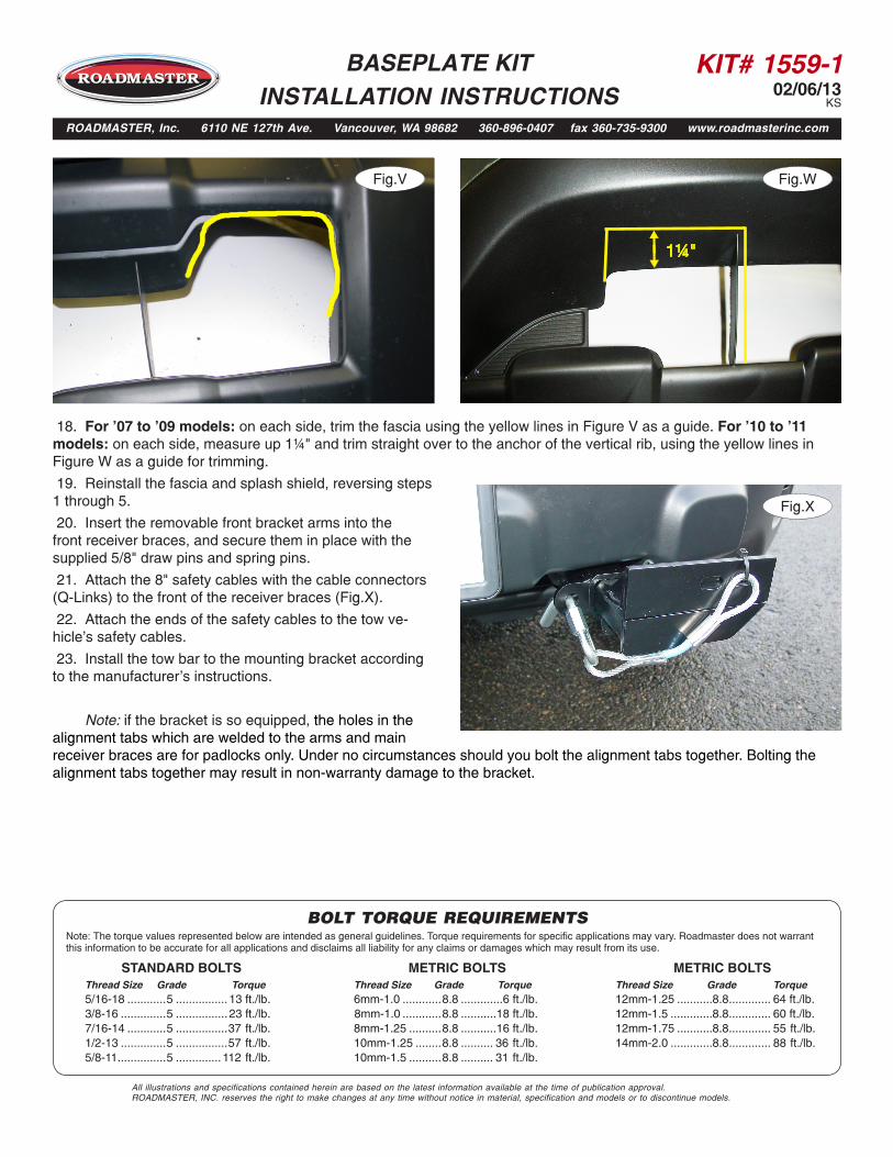
18. For '07 to '09 models: on each side, trim the fascia using the yellow lines in Figure V as a guide. For '10 to '11models: on each side, measure up 1¼" and trim straight over to the anchor of the vertical rib, using the yellow lines inFigure W as a guide for trimming.
Fig.V
Fig.X
BASEPLATE KIT INSTALLATION INSTRUCTIONS
ROADMASTER, Inc. 6110 NE 127th Ave. Vancouver, WA 98682 360-896-0407 fax 360-735-9300 www.roadmasterinc.com
Fig.W
19. Reinstall the fascia and splash shield, reversing steps1 through 5.
20. Insert the removable front bracket arms into thefront receiver braces, and secure them in place with thesupplied 5/8" draw pins and spring pins.
21. Attach the 8" safety cables with the cable connectors(Q-Links) to the front of the receiver braces (Fig.X).
22. Attach the ends of the safety cables to the tow ve-hicle's safety cables.
23. Install the tow bar to the mounting bracket accordingto the manufacturer's instructions.
Note: if the bracket is so equipped, the holes in the alignment tabs which are welded to the arms and main
All illustrations and specifications contained herein are based on the latest information available at the time of publication approval. ROADMASTER, INC. reserves the right to make changes at any time without notice in material, specification and models or to discontinue models.
1¼"
BOLT TORQUE REQUIREMENTS
METRIC BOLTSThread Size Grade Torque12mm-1.25 ...........8.8 ............. 64 ft./lb. 12mm-1.5 .............8.8 ............. 60 ft./lb.12mm-1.75 ...........8.8 ............. 55 ft./lb.14mm-2.0 .............8.8 ............. 88 ft./lb.
METRIC BOLTSThread Size Grade Torque6mm-1.0 ............8.8 .............6 ft./lb. 8mm-1.0 ............8.8 ...........18 ft./lb. 8mm-1.25 ..........8.8 ...........16 ft./lb.10mm-1.25 ........8.8 .......... 36 ft./lb.10mm-1.5 ..........8.8 .......... 31 ft./lb.
STANDARD BOLTSThread Size Grade Torque5/16-18 ............5 ................ 13 ft./lb. 3/8-16 ..............5 ................ 23 ft./lb.7/16-14 ............5 ................37 ft./lb.1/2-13 ..............5 ................57 ft./lb.5/8-11 ...............5 .............. 112 ft./lb.
Note: The torque values represented below are intended as general guidelines. Torque requirements for specific applications may vary. Roadmaster does not warrant this information to be accurate for all applications and disclaims all liability for any claims or damages which may result from its use.
receiver braces are for padlocks only. Under no circumstances should you bolt the alignment tabs together. Bolting the alignment tabs together may result in non-warranty damage to the bracket.