Embed Size (px)
Citation preview

Installation InstructionsI DIRECT DRIVE BLOWER
Three PhasePA55/PAPA SERI ES
SINGLEPACKAGEAIRCONDITIONERS
ELECTRIC / @ELECTRICHEAT(OPTIONAL)c
TABLEOF CONTENTS
1, Safety Labelingand Signal Words .......................... 2
Danger, Warning and Caution ................................... 2
2. Safe Installation Requirements ..................... 2
3. Locating The Unit .................................. 2
Clearances ................................................... 2
Dimensions ................................................... 2
Minimum Clearances to ComLJstibte Construction 3
Installation ................................................... 3
Installing Duct Collars .. 3
_'ondensate Drain ,1
4. Electrical Wiring .................................. 4
Ground Connections ........................................... 4
Line Voltage Wiring ............................................ 4Unit Disconnect ............................................... 4
Converting 230M tJnils to 208V ................................... 4
Low Voltage Wiring ........................................... 4
Thermostat Connections ........................................ 5
Field Installed Equipment ........................................ 5
5. Electric Heat Installation ............................. 6
General Information .......................................... 6
Adjustinc Thermostat Anticipator ....... 6
Limit Controls ....... 6
Operation ........ 6
Install Heater ................................................. 6
Heater Wiring ................................................. 6
Grounding ..................... 6
Installing Wrong 6
Unit Disconnect Breaker ......................................... 8
Rain Shield Installation ........................................ 8
6. Air Distribution System .............................. 8
Ductwork .................................................... 8DuctworkInsulation.. ..... 8
DactwerkConnections........ 8
Filters ........................................................ 8
7. Start-up Procedul'es ................................ 9
Final Electrical Check ........................................... 9
Circulating Air Blower ......................................... 9
DeterminingE ower Speed ......... g
BDeedTai3s .................. 9
Cooling and AuxiliaryElectric StripHeat ............................ 9Check Before Starting .......................................... 9
CirculatingAir Blower ......... 10
Cooling ..................................... 10
Auxiliary _ea[mg ......................... 10
Temperature Rise Check ..... i,,. ................................ 10
Sequence of Operation , .................................... 10
CoolingMode:Energizan RGY'_) De_ene_gized(NA ............... 10
8. Operation ............................................ 11
ScrollAnti-Cycle Timer {Wh_reApplicai:31e}......................... 11Turning The UnitOff ............................................... 11
ThermostatFanSwitchOperation...,, ........................... 11AdjustingRoom Temperatures .... .., ........................... 11
13, Maintenance ...................................... 11
MonthlyMaintenanceand Inspection Checks ....................... 11Air Fitters . 11
Cooling Season Checks (Monthly} ................................ 11CondenserCo ..... 11
CondensateDrain... 11
AnnualMaintenanceand inspection .............................. 1tCondenserFanMotor 11
CircaiatingAir Blower 12
Printed in U.S.A. 426 O1 1OO5 CO1o/15/Ol
1. Safety Labeling and Signal Words
Danger, Warning and Caution
The signal words DANGER, WARNING and CAUTION are used
to identify levels of hazard seriousness. The signal word DAN-GER is only used on product labels to signify an immediate haz-
ard. The signal words WARNING and CAUTION will be used onproduct labels and throughout this manual and other manuals thatmay apply to the product.
2. Safe Installation Requirements
Installation or repairs made by unqualified persons can result
in hazards to you and others. Installation MUST conform withlocal building codes or, in the absence of local codes, with theNational Electrical Code NFPA70-1990 or current edition.
The information contained in this manual is intended for use
by a qualified service technician familiar with safety proce-dures and equipped with the proper tools and test instru-ments.
Failure to carefully read and follow all instructions in thismanual can result in unit malfunction, property damage, per-
sonal injury and/or death.
• Seal supply and return air ducts.
• Check to see that filters are installed correctly and are theproper type and size.
NOTE: It is the personal responsibility and obligation of the cus-tomer to contact a qualified installer to ensure that the installationis adequate and conforms to governing codes and ordinances.
Dimensions
CAUTION
Do NOT operate unit in a corrosive atmosphere containing
chlorine, fluorine, or any other corrosive chemicals.
3. Locating & Installing The Unit
The unit is designed for outdoor installation only. Place the unit ona platform at ground level. The unit may be installed on a concrete
slab of 48" (1219mm) x 48" (1219mm) dimensions. Cementblocks on a 3" sand footing will also work. The slab or blocks
SHOULD NOT be in contact with any part of the structure. Checklocal codes covering zoning, noise, platforms, etc..
If practical avoid locating next to fresh air intakes, vent or bed-
room windows. Noise may carry into the openings and disturbpeople inside.
Avoid installations under roof overhangs without guttering. Water
draining from the roof onto the unit could produce excessivenoise, and may cause ice to build up on coil or fan.
Placement of the unit should be in a well drained area or the unit
MUST be supported high enough so runoff will not enter the unit.
Do not locate unit where heat, lint or exhaust fumes wil! be dis-charged on unit (as from dryer vents.)
Clearances
Minimum clearances, as specified in FIGURE 1, MUST be main-tained from adjacent structures to provide adequate air circula-
tion and room for service personnel.
While minimum clearances are acceptable for safety reasons,they may not allow adequate air circulation around the unit for
proper operation. Whenever possible, it is desirable to allow addi-tional clearance, especially around the condenser inlet and dis-
charge openings.
Do NOT install the unit in a recessed or confined area that will per-mit discharged air from the condenser to recirculate to the con-denser inlet.
T26.5
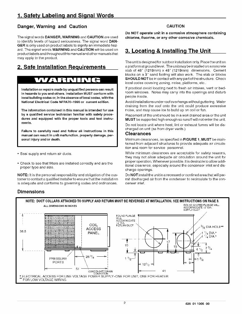
NOTE: DUCT COLLARS ATTACHED TO SUPPLY AND RETURN MUST BE REVERSED AT INSTALLATION. SEE INSTRUCTIONS ON PAGE 3.
ALL DIMENSIONS IN INCHES ROUND SHAPED FLANGE WILLACCOMMODATE 12" DtA.SUPPLY DUCT
ROUND FLANGE r /IIIl_ll_1_LI1_1_l]_l_ll_m I_1_11m]11_1111_111 WILL
ACCOMMODATE14D,AIlllHlllliltllliHla#ltlillllti/i_ll_Jlltll_iltlialtlla RETURN DUCT DIA HOLE**
_llllllllllll[llllll_ftlllllt_illlllJlllltlllit#lll_ll_
COILACCESS
PANEL
10
PRpEoSSUsRE_/_ 263/4 _ 1
<_ 61 \CONDENSATE DRAIN 41
CONECTION* ELECTRICAL ACCESS FOR LINE VOLTAGE POWER SUPPLY-ONE FOR UNIT, ONE FOR HEATER** FOR LOW VOLTAGE WIRING
3/4
2 426 01 1005 00
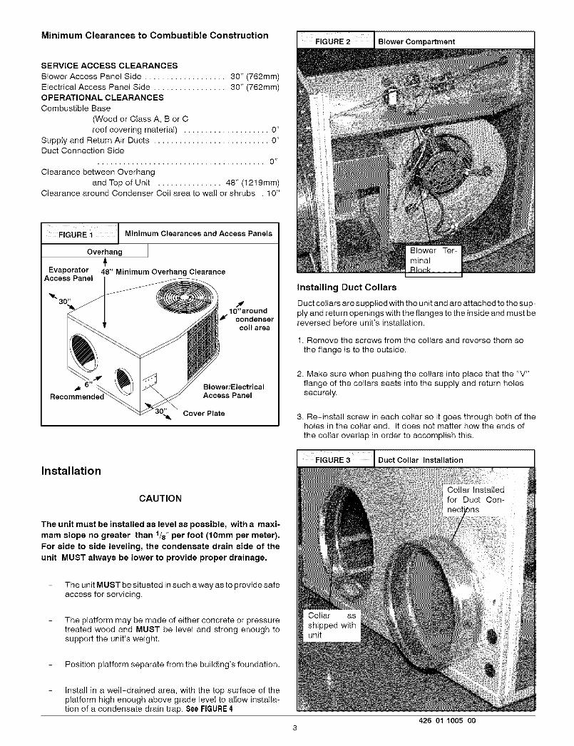
Minimum Clearances to Combustible Construction ......
SERVICE ACCESS CLEARANCES
Blower Access Pane! Side ................... 30" (762mm)
Electrical Access Panel Side ................. 30" (762mm)OPERATIONAL CLEARANCES
Combustible Base
(Wood or Class A, B or C
roof covering material) .................... 0"
Supply and Return Air Ducts ........................... 0"Duct Connection Side
....................................... 0 _
Clearance between Overhang
and Top of Unit ............... 48" (1219mm)Clearance around Condenser Coil area to wall or shrubs . 10"
FIGURE i Minimum Clearances and Access Panels
Overhang
Evaporator 48" Minimum Overhang ClearanceAccess Panel
JlO"around
f condensercoilarea
6 _ Blower/ElectricalAccess Panel
,,_ Cover Plate
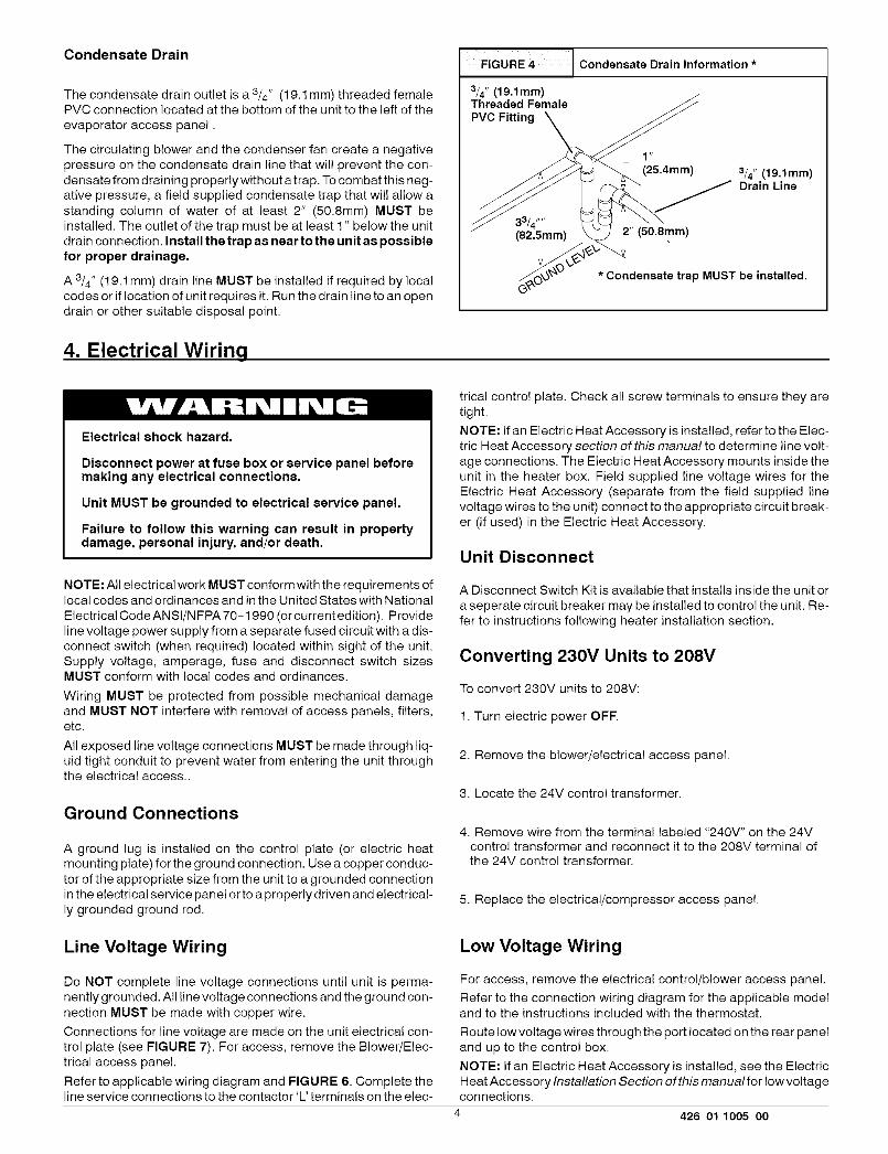
Installing Duct Collars
Duct collars are supplied with the unit and are attached to the sup-
ply and return openings with the flanges to the inside and must bereversed before unit's installation.
1. Remove the screws from the collars and reverse them sothe flange is to the outside.
2. Make sure when pushing the collars into place that the "V"flange of the collars seats into the supply and return holessecurely.
3. Re-install screw in each collar so it goes through both of theholes in the collar end. It does not matter how the ends of
the collar overlap in order to accomplish this.
Installation
CAUTION
The unit must be installed as level as possible, with a maxi-mam slope no greater than 1/8" per foot (lOmm per meter).
For side to side leveling, the condensate drain side of the
unit MUST always be lower to provide proper drainage.
The unit MUST be situated in such a way as to provide safeaccess for servicing.
The platform may be made of either concrete or pressuretreated wood and MUST be level and strong enough tosupport the unit's weight.
Position platform separate from the building's foundation.
Install in a well-drained area, with the top surface of theplatform high enough above grade level to allow installa-tion of a condensate drain trap. See FIGURE 4
FIGURE 3 I Duct Collar Installation
426 01 1005 O03
Condensate Drain
The condensate drain outlet is a 3/4" (19.1 mm) threaded femalePVC connection located at the bottom of the unit to the left of the
evaporator access panel.
The circulating blower and the condenser fan create a negative
pressure on the condensate drain line that will prevent the con-densate from draining properly without a trap. To combat this neg-ative pressure, a field supplied condensate trap that will allow a
standing column of water of at least 2" (50.8mm) MUST beinstalled. The outlet of the trap must be at least 1" below the unit
drain connection. Install the trap as near to the unit as possiblefor proper drainage.
A 3/4" (19.1 mm) drain line MUST be installed if required by localcodes or if location of unit requires it. Run the drain line to an open
drain or other suitable disposal point.
4. Electrical Wiring
FIGURE 4 J Condensate Drain Information*
3/4" (19.1mm)Threaded FemalePVC Fitting
33/4 t_ .
(82.5mm)
(25.4mm) 3/4" (19.1mm)Drain Line
2" (50.8mm)
* Condensate trap MUST be installed.
Electrical shock hazard.
Disconnect power at fuse box or service panel beforemaking any electrical connections.
Unit MUST be grounded to electrical service panel.
Failure to follow this warning can result in propertydamage, personal injury, and/or death.
NOTE: All electrical work MUST conform with the requirements oflocal codes and ordinances and in the United States with National
Electrical Code ANSI/NFPA 70-1990 (or current edition). Provide
line voltage power supply from a separate fused circuit with a dis-connect switch (when required) located within sight of the unit.Supply voltage, amperage, fuse and disconnect switch sizesMUST conform with local codes and ordinances.
Wiring MUST be protected from possible mechanical damageand MUST NOT interfere with removal of access panels, filters,etc.
All exposed line voltage connections MUST be made through liq-uid tight conduit to prevent water from entering the unit throughthe electrical access..
Ground Connections
A ground lug is installed on the control plate (or electric heatmounting plate) for the ground connection. Use a copper conduc-
tor of the appropriate size from the unit to a grounded connectionin the electrical service panel or to a properly driven and electrical-
ly grounded ground rod.
Line Voltage Wiring
Do NOT complete line voltage connections until unit is perma-nently grounded. All line voltage connections and the ground con-
nection MUST be made with copper wire.
Connections for line voltage are made on the unit electrical con-trol plate (see FIGURE 7). For access, remove the Blower/Elec-
trical access panel.
Refer to applicable wiring diagram and FIGURE 6. Complete theline service connections to the contactor 'L' terminals on the elec-
trical control plate. Check all screw terminals to ensure they aretight.
NOTE: If an Electric Heat Accessory is installed, refer to the Elec-tric Heat Accessory section of this manual to determine line volt-
age connections. The Electric Heat Accessory mounts inside theunit in the heater box. Field supplied line voltage wires for the
Electric Heat Accessory (separate from the field supplied linevoltage wires to the unit) connect to the appropriate circuit break-er (if used) in the Electric Heat Accessory.
Unit Disconnect
A Disconnect Switch Kit is available that installs inside the unit or
a seperate circuit breaker may be installed to control the unit. Re-
fer to instructions following heater installation section.
Converting 230V Units to 208V
To convert 230V units to 208V:
1. Turn electric power OFE
2. Remove the blower/electrical access panel.
3. Locate the 24V control transformer.
4. Remove wire from the terminal labeled "240V" on the 24Vcontrol transformer and reconnect it to the 208V terminal ofthe 24V control transformer.
5. Replace the electrical/compressor access panel.
Low Voltage Wiring
For access, remove the electrical control/blower access panel.
Refer to the connection wiring diagram for the applicable modeland to the instructions included with the thermostat.
Route low voltage wires through the port located on the rear panel
and up to the control box.
NOTE: If an Electric Heat Accessory is installed, see the Electric
Heat Accessory Installation Section of this manual for low voltageconnections.
4 426 01 1005 00

Thermostat Connections
The location of the thermostat has an important effect on the op-eration of the unit. See the thermostat instructions for proper con-nection. See FIGURE 5 for Low Voltage Wire HarnessConnections
Field Installed Equipment
Wiring to be done in the field between the unit and other devices,or between separate devices which are field installed and located,MUST NOT exceed the temperature limitations for type T wireand MUST be installed according to the manufacturer's instruc-tions for the devices.
FIGURE 5 I HarnessElectr°niCconnectionTherm°statDiagramL°WVoltage Wi ring
Typical Thermostat Subbase
[c] [?] [R,] _ _,]I I I I I
I I I I I
_ _ _ _ (when used)I I I I /
i i i i AI I I I I
I
[Blue] [Green] [F_ed] [Yellow] [White] _[
Corn Fan 24V Comp Elect.(when Cool Heatused) Acces.
Unit Low Voltage Wiring Harness.
FIGURE 6 I Typical Connections at Unit
USE COPPER CONDUCTORS ONLY2g8/23gV 60HZ 3PH
FIGURE 7 Control Box Configuration
Outdoor Fan f._ '_-_ t
copao,tor\ _0-:__"_c;: o;en,
Bl°wer Relay °r Sequence L __2_"_///_
Transformer%___ ___/__/_Anti-Cycle Time J_.X_ _ I_:_"_:;_ j_f /'_" Control Box
Volt Wire Entrance
_owvo,twireEntrance_ _.__ __i_i
Wire
426 01 1005 O05
5. Electric Heat Installation
General Information
Adjusting Thermostat Anticipator
Set the heat anticipator of the thermostat to the proper value. Seeinstructions provided with the thermostat before making this ad-justment.
Model Number Anticipator SettingAMMH10AHB .36AMMH15AHB .36
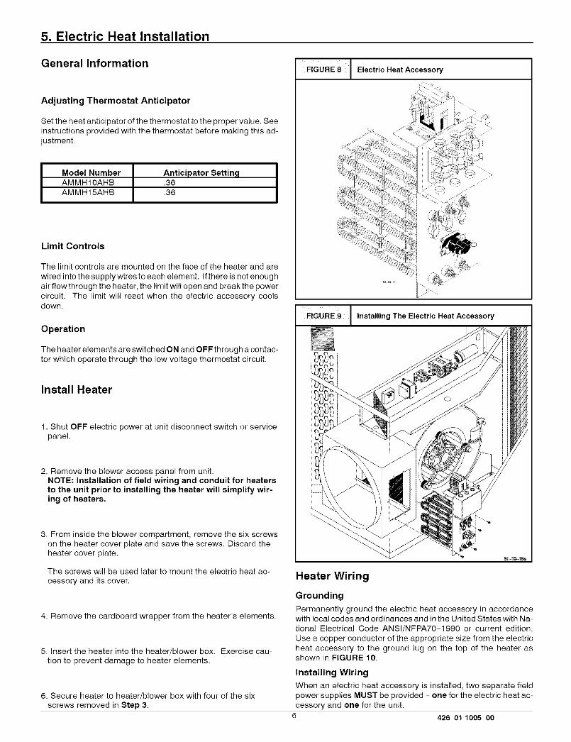
Limit Controls
The limit controls are mounted on the face of the heater and are
wired into the supply wires to each element. If there is not enough
air flowthrough the heater, the limit will open and break the powercircuit. The limit will reset when the electric accessory coolsdown.
Operation
The heater elements are switched ON and OFF through a contac-tor which operate through the low voltage thermostat circuit,
Install Heater
1. Shut OFF electric power at unit disconnect switch or servicepanel.
2. Remove the blower access panel from unit,NOTE: Installation of field wiring and conduit for heatersto the unit prior to installing the heater will simplify wir-ing of heaters.
3. From inside the blower compartment, remove the six screwson the heater cover plate and save the screws. Discard theheater cover plate.
The screws will be used later to mount the electric heat ac-
cessory and its cover.
4. Remove the cardboard wrapper from the heater's elements.
5. Insert the heater into the heater/blower box. Exercise cau-tion to prevent damage to heater elements.
6. Secure heater to heater/blower box with four of the sixscrews removed in Step 3.
FIGURE 8 Electric Heat Accessory
:Z_ ii i
;;;_ 9!
t; b>:!!_
FIGURE 9 I Installing The Electric Heat Accessory
Heater Wiring
Grounding
Permanently ground the electric heat accessory in accordancewith local codes and ordinances and in the United States with Na-
tional Electrical Code ANSl/NFPA70-1990 or current edition.
Use a copper conductor of the appropriate size from the electric
heat accessory to the ground lug on the top of the heater asshown in FIGURE 10.
Installing WiringWhen an electric heat accessory is installed, two separate field
power supplies MUST be provided - one for the electric heat ac-cessory and one for the unit.
6 426 01 1005 oo
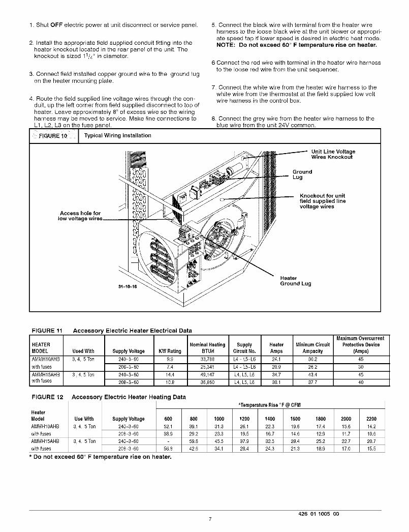
1. Shut OFF electric power at unit disconnect or service panel.
2. Install the appropriate field supplied conduit fitting into theheater knockout located in the rear panel of the unit. Theknockout is sized 11/4" in diameter.
3. Connect field installed copper ground wire to the ground lugon the heater mounting plate.
5. Connect the black wire with terminal from the heater wire
harness to the loose black wire at the unit blower or appropri-ate speed tap if lower speed is desired in electric heat mode.NOTE: Do not exceed 60 ° F temperature rise on heater.
Connect the red wire with terminal in the heater wire harness
to the loose red wire from the unit sequencer.
4. Route the field supplied line voltage wires through the con-duit, up the left corner from field supplied disconnect to top ofheater. Leave approximately 8" of excess wire so the wiringharness may be moved to service. Make line connections toL1, L2, L3 on the fuse panel.
FIGURE i0 Typical Wiring Installation
7. Connect the white wire from the heater wire harness to the
white wire from the thermostat at the field supplied low voltwire harness in the control box.
8. Connect the grey wire from the heater wire harness to theblue wire from the unit 24V common.
Unit Line VoltageWires Knockout
GroundLug
Access hole forlow voltage
Knockout for unitfield supplied linevoltage wires
31-10-16
HeaterGround Lug
FIGURE 11
HEATERMODEL
AMMH10AHB
withfuses
AMMH15AHBwithfuses
Accessory Electric Heater Electrical Data
UsedWith
3,4, 5T0n
3,4,5T0n
Supply Voltage
240-3-60
208-3-60
240-3-60
208-3-60
KW Rating9.9
7.4
14.4
10.8
Nominal HeatingBTUH
33,788
25,341
49,147
36,860
SupplyCircuit No,
L4 - L5-L6
L4 - L5-L6
L4, L5, L6
L4, L5, L6
Heater
Amps24.1
20.9
34.7
30.1
Mininum Circuit
Ampacity30.2
26.2
43.4
37.7
MaximumOvercurrentProtectiveDevice
(Amps}45
30
45
4O
FIGURE 12
HeaterModel
AMMHIOAHBwithfuses
AMMH15AHB
withfuses
Accessor
Use With
3,4, 5Ton
3,4, 5Ton
Electric Heater Heating Data*TemperatureRise °F @ CFM
Supply Voltage 600 800 1000 1200 1400 1600 1800 2000 2200
240-3-60 52.1 39.1 31.3 26.1 22.3 19.6 17.4 15.6 14.2
208-3-60 38.9 29.2 23.3 19.5 16.7 14.6 12.9 11.7 10.6
240-3-60 59.6 45.5 37.9 32.5 28.4 25.2 22.7 20.7
208-3-60 56.8 42.6 34.1 28.4 24.3 21.3 18.9 17.0 15.5
* Do not exceed 60 ° F temperature rise on heater,
426 01 1005 O07
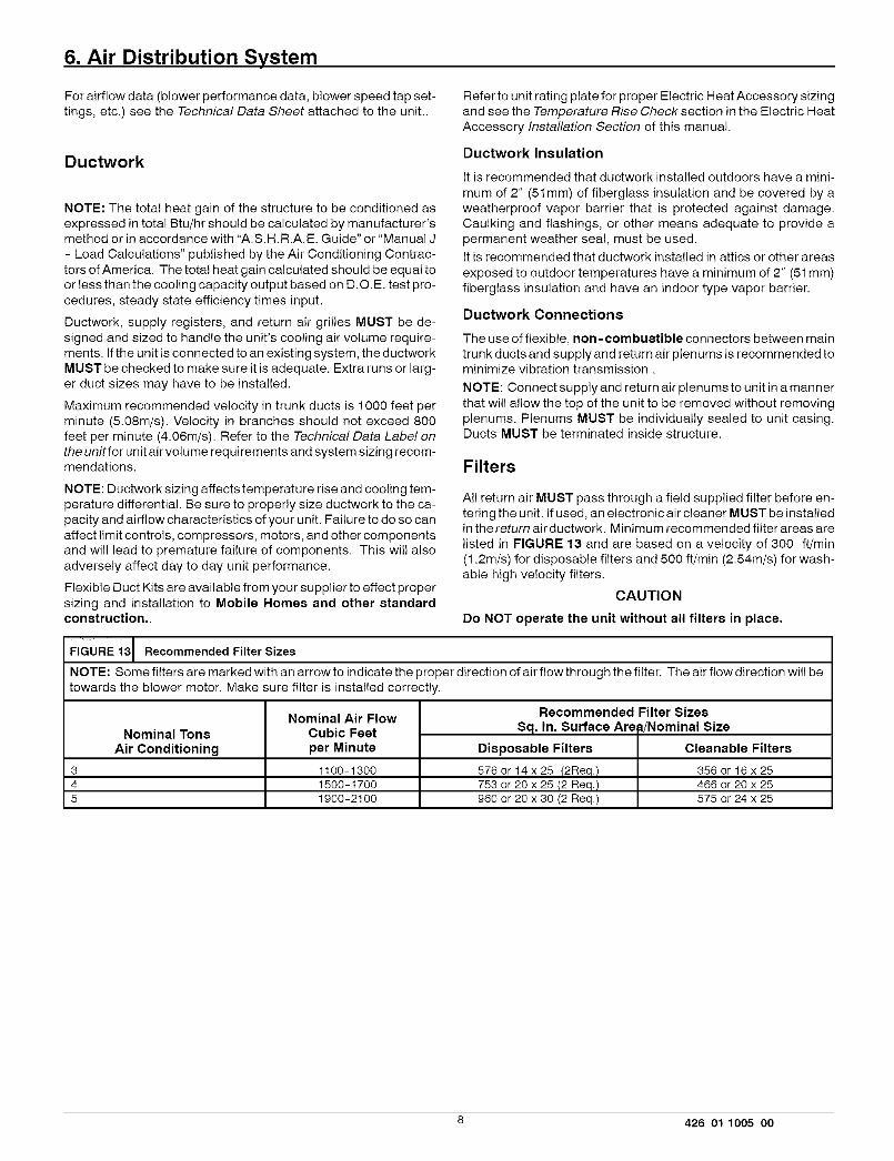
6. Air Distribution System
For airflow data (blower performance data, blower speed tap set-
tings, etc.) see the Technical Data Sheet attached to the unit..
Refer to unit rating plate for proper Electric Heat Accessory sizing
and see the Temperature Rise Check section in the Electric HeatAccessory Installation Section of this manual.
Ductwork
NOTE: The total heat gain of the structure to be conditioned as
expressed in total Btu/hr should be calculated by manufacturer'smethod or in accordance with "A.S.H.R.A.E. Guide" or "Manual J
- Load Calculations" published by the Air Conditioning Contrac-
tors of America. The total heat gain calculated should be equal toor less than the cooling capacity output based on D.C.E. test pro-
cedures, steady state efficiency times input.
Ductwork, supply registers, and return air grilles MUST be de-signed and sized to handle the unit's cooling air volume require-
ments. If the unit is connected to an existing system, the ductworkMUST be checked to make sure it is adequate. Extra runs or larg-er duct sizes may have to be installed.
Maximum recommended velocity in trunk ducts is 1000 feet per
minute (5.08m/s). Velocity in branches should not exceed 800feet per minute (4.06m/s). Refer to the Technical Data Label onthe unitfor unit air volume requirements and system sizing recom-mendations.
NOTE: Ductwork sizing affects temperature rise and cooling tem-perature differential. Be sure to properly size ductwork to the ca-
pacity and airflow characteristics of your unit. Failure to do so canaffect limit controls, compressors, motors, and other componentsand will lead to premature failure of components. This wil! also
adversely affect day to day unit performance.
Flexible Duct Kits are available from your supplier to effect propersizing and installation to Mobile Homes and other standardconstruction..
Ductwork Insulation
It is recommended that ductwork installed outdoors have a mini-
mum of 2" (51 mm) of fiberglass insulation and be covered by aweatherproof vapor barrier that is protected against damage.
Caulking and flashings, or other means adequate to provide apermanent weather seal, must be used.
It is recommended that ductwork installed in attics or other areas
exposed to outdoor temperatures have a minimum of 2" (51 mm)
fiberglass insulation and have an indoor type vapor barrier.
Ductwork Connections
The use of flexible, non -combustible connectors between maintrunk ducts and supply and return air plenums is recommended tominimize vibration transmission.
NOTE: Connect supply and return air plenums to unit in a mannerthat will allow the top of the unit to be removed without removingplenums. Plenums MUST be individually sealed to unit casing.Ducts MUST be terminated inside structure.
Filters
All return air MUST pass through afield supplied filter before en-tering the unit. If used, an electronic air cleaner MUST be installedin thereturn air ductwork. Minimum recommended filter areas are
listed in FIGURE 13 and are based on a velocity of 300 ft/min(1.2m/s) for disposable filters and 500 ft/min (2.54m/s) for wash-able high velocity filters.
CAUTION
Do NOT operate the unit without all filters in place.
FIGURE 13 Recommended Filter Sizes
NOTE: Some filters are marked with an arrow to indicate the proper direction of air flow through the filter. The air flow direction will betowards the blower motor. Make sure filter is installed correctly.
345
Nominal TonsAir Conditioning
Nominal Air FlowCubic Feet
per Minute
1100-13001500-17001900-2100
Recommended Filter Sizes
Sq. In. Surface Arefi/Nominal Size
Disposable Filters Cleanable Filters
576 or 14 x 25 (2Req.) 356 or 16 x 25753 or 20 x 25 (2 Req.) 466 or 20 x 25960 or 20 x 30 (2 Req.) 575 or 24 x 25
8 426 01 1005 O0
7. Start-up Procedures
Electrical shock hazard.
Use extreme care during all of the following checks and pro-cedures.
Make sure electric power is turned OFF as instructed in ap-propriate steps.
Failure to follow this warning can result in property damage,personal injury, and/or death.
Final Electrical Check
Make a final wiring check to be sure system is correctly wired. In-spect field installed wiring and the routing to ensure that rubbingor chafing due to vibration will not occur.
NOTE: Wiring MUST be installed so it is protected from possiblemechanical damage.
Circulating Air Blower
Determining Blower Speed
1. Turn electric power OFF.
2. From the system design, determine the total external staticpressure (ESP) for the supply ducts, return ducts and regis-ters, diffusers, grilles, dampers, heaters and filters.
3. To your system ESP determined in Step 2, add 0.05 In. W.C.for a wet coi!.
4. From the system design, determine the desired cooling air-flow in cubic feet per minute (CFM).
5. Locate the unit's Blower Performance Data table on the tech
data label for the unit's voltage. (The tech data sheet is at-tached to the evaporator access panel on the unit.) From thetable, determine the speed tap required to achieve the de-sired airflow.
6. See next section, Speed Taps, to set the blower motorspeed terminal block (speed taps) to the cooling speed deter-mined in the previous steps.
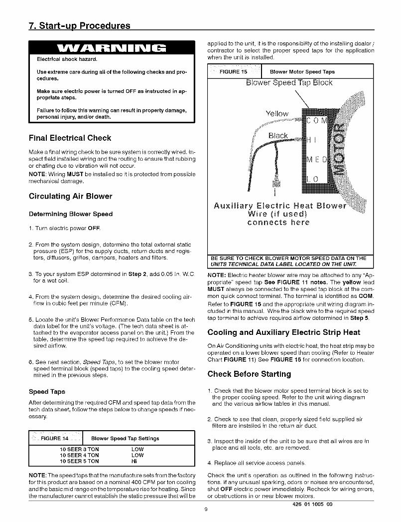
Speed Taps
After determining the required CFM and speed tap data from thetech data sheet, follow the steps below to change speeds if nec-essary.
FIGURE i4 [ Blower Speed Tap Settings
10 SEER 3 TON LOW10 SEER 4 TON LOW10 SEER 5TON HI
NOTE: The speed taps that the manufacture sets from the factoryfor this product are based on a nominal 400 CFM per ton coolingand the basic mid range on the temperature rise for heating. Sincethe manufacturer cannot establish the static pressure that will be
applied to the unit, it is the responsibility of the installing dealer /contractor to select the proper speed taps for the applicationwhen the unit is installed.
IO.ow.,MotorSpeedTapsBlower Speed Tap Block
Auxiliary Electric Heat BWire (if used)connects here
BE SURE TO CHECK BLOWER MOTOR SPEED DATA ON THEUNITS TECHNICAL DATA LABEL LOCATED ON THE UNIT.
NOTE: Electric heater blower wire may be attached to any "Ap-propriate" speed tap See FIGURE 11 note8. The yellow leadMUST always be connected to the speed tap block at the com-mon quick connect terminal. The terminal is identified as COM.
Refer to FIGURE 15 and the appropriate unit wiring diagram in-cluded in this manual. Wire the black wire to the required speedtap terminal to achieve required airflow determined in Step 5.
Cooling and Auxiliary Electric Strip Heat
On Air Conditioning units with electric heat, the heat strip may beoperated on a lower blower speed than cooling (Refer to Heater
Chart FIGURE 11) See FIGURE 15 for connection location.
Check Before Starting
1. Check that the blower motor speed terminal block is set tothe proper cooling speed. Refer to the unit wiring diagramand the various airflow tables in this manual.
2. Check to see that clean, properly sized field supplied airfilters are installed in the return air duct.
3. Inspect the inside of the unit to be sure that all wires are inplace and all tools, etc. are removed.
4. Replace all service access panels.
Check the unit's operation as outlined in the following instruc-tions. If any unusual sparking, odors or noises are encountered,
shut OFF electric power immediately. Recheck for wiring errors,or obstructions in or near blower motors.
426 01 1005 009
Circulating Air Blower
1. Be sure electric power is OFF.
2. Set thermostat Heat-Cool selector to OFF.
3. Set thermostat fan switch to AUTO.
4. Turn electric power ON. Nothing should start running,
5. Set thermostat fan switch to ON. The circulating air blowershould come ON after a 30 second delay.
6. Reset thermostat fan switch to AUTO. The circulating airblower should go OFF after a 30 second delay. Nothingshould be running.
Cooling
1. Be sure that electric power is OFF.
2. Set thermostat Heat-Coo! select to COOL.
3. Adjust thermostat setting to below room temperature.
4. Turn electric power ON. During power application check thefollowing:
a. Contactor - Contacts closingb. Compressor - ONc. Condenser fan motor - ON
d. Circulating air blower - ON (after delay)
5. Switch the thermostat to OFF, check the following:
a. Contactor contacts opening.b. Compressor - OFFc. Condenser fan motor - OFFd. Circulating blower - OFF (after delay)
6. Turn electric power OFF
Auxiliary Heating
NOTE: Repeat circulating air blower procedure above if AuxiliaryElectric Heat is being installed after unit has been installed andchecked out.
Temperature Rise Check
Temperature rise is the difference between the supply and returnair temperatures. The temperature rise should be ± 2 ° F (!. 1°C) of
the temperature rise shown in FIGURE 12.
NOTE: The temperature rise can be adjusted by changing thespeed tap at the unit's blower terminal block. Refer to the unit'sInstallation Instructions for airflow information.
A temperature rise greater than 60°F (33.3°C) is not recom-mended. (This applies to electric heat only).
1. To check the temperature rise through the unit, place ther-mometers in the supply and return air ducts as close to theunit as possible.
2. Open ALL registers and duct dampers.
3. Set thermostat Heat-Cool selector to HEAT.
4. Set the thermostat temperature setting as high as it wil! go.
5. Turn electric power ON.
6. Operate unit AT LEAST 5 minutes, then check temperaturerise.
NOTE: The maximum outlet air temperature for all models is200°F (93.35C). Maximum temperature rise for electric heat is60°F (33.35C)
7. Set thermostat to normal temperature setting.
8. Turn electric power OFE
9. Change blower speed tap if 60°F (33.3°C)TemperatureRisewasexceededand repeat.
10. Be sure to seal all holes in ducts if any were created duringthis process.
Sequence of Operation
Cooling Mode: Energized (R,G,Y1) De-energized(N/A)
(a) When high and low voltage is initially applied to unit:
(1)On a call for cooling ......... :The compressor and condenser fan will energize. The evap-orator blower motor will have a delay on and will energizeafter 30 seconds.
(2)When the cooling setpoint has been satisfied ......... :The compressor and condenser fan will de-energize immedi-ately. The evaporator blower motor will have a delay off andwill de-energize after 30 seconds.
If temperature rise is excessive, verify proper airflow through theunit. If temperature rise is inadequate, check for proper electrical
supply to the heater and verify correct airflow.
10 426 01 1005 O0
8. Operation
Electrical shock hazard.
Turning The Unit Off
Turn OFF electric power supply at disconnect switch or ser-vice panel before removing any access or service panel fromunit.
Failure to follow this warning can result in property damage,
personal injury, and/or death.
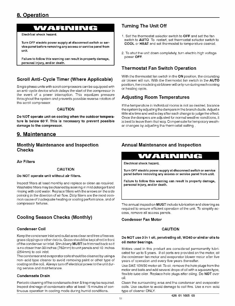
Scroll Anti-Cycle Timer (Where Applicable)
Single phase units with scroll compressors can be equipped with
an anti-cycle device which delays the start of the compressor inthe event of a power interruption. This equalizes pressurethroughout the system and prevents possible reverse rotation of
the scroll compressor.
CAUTION
Do NOT operate unit on cooling when the outdoor tempera-
ture is below 60°F. This is necessary to prevent possibledamage to the compressor.
1. Set the thermostat selector switch to OFF and set the fan
switch to AUTO. To restart, set thermostat selector switch toCOOL or HEAT and set thermostat to temperature desired.
2. To shut the unit down completely, turn electric high voltagepower OFF.
Thermostat Fan Switch Operation
With the thermostat fan switch in the ON position, the circulatingair blower will run. With the thermostat fan switch in the AUTO
position, the circulating air blower will only run during each coolingor heating cycle.
Adjusting Room Temperatures
If the temperature in individual rooms is not as desired, balancethe system by adjusting the dampers in the branch ducts. Adjust alittle at a time and wait a day after each change to judge the effect.
Once the dampers are adjusted for normal weather conditions, itis best to leave them that way. Compensate for temporary weath-er changes by adjusting the thermostat setting.
9. Maintenance
Monthly Maintenance and InspectionChecks
Annual Maintenance and Inspection
Air Filters
CAUTION
Do NOT operate unit without air filters.
Inspect filters at least monthly and replace or clean as required.
Washable filters may be cleaned by soaking in mild detergent andrinsing with cold water. Replace filters with the arrows on the side
pointing in the direction of air flow. Dirty filters are the most com-mon cause of inadequate heating or cooling performance, and of
compressor failures.
Cooling Season Checks (Monthly)
Electrical shock hazard.
Turn OFF electric power supply at disconnect switch or servicepanel before removing any access or service panel from unit.
Failure to follow this warning can result in property damage,personal injury, and/or death.
The annual inspection MUST include lubrication and cleaning asrequired to ensure efficient operation of the unit. To simplify ac-cess, remove all access panels.
Condenser Fan Motor
Condenser Coil CAUTION
Keep the condenser inlet and outlet area clean and free of leaves,grass clippings or other debris. Grass should be kept short in front
of the condenser air inlet. Shrubbery MUST be trimmed back so itis no closer than 30 inches (762mm) to unit panels and 10 inches(254mm) to coil inlet.
The condenser and evaporator coils should be cleaned by using anon-acid type cleaner to avoid removing paint or other type of
coating on the coil. Always turn off electrical power to the unit dur-ing service and maintenance.
Condensate Drain
Periodic cleaning of the condensate drain & trap may be required.
Inspect drainage of condensate after at least 15 minutes of con-tinuous operation in cooling mode during humid conditions.
Do NOT use 3 in 1 oil, penetrating oil, WD40 or similar oils to
oil motor bearings.
Motors used in this product are considered permanently lubri-
cated for up to 5 years. If oil ports are provided on the motor, oilthe condenser fan motor and evaporator blower motor after fiveyears of operation and every five years thereafter.
Use SAE 10W30 motor oil. To oil, remove the hole plugs from themotor end bells and add several drops of oil with a squeeze type,
flexible tube oiler. Replace hole plugs after oiling. Do NOT overoil.
Clean the surrounding area and the condenser and evaporator
coils. Use caution to avoid damage to coi! fins. Use a non-acidtype of cleaner ONLY.
426 01 1005 0011
Circulating Air Blower
To access or remove the blower motor use the following steps.
1. Turn electric power OFF.
2. Remove the blower access panel.
3. Unplug the wires connected to the speed tap block if neces-sary, noting the location of each wire for re-installation.
4. Slide entire housing toward you.
5. Visually inspect the blower wheel for accumulations of dirt orlint. Clean the compartment and the blower wheel. If accu-
mulation is excessive on blower wheel, or does not easilyremove, it may be necessary to remove and disassemble theblower assembly for proper cleaning.
6. Oil blower motor if needed.
CAUTION
Do NOT use 3 in 1 oil, penetrating oil, WD40 or similar oils tooil motor bearings.
Oil the blower motor by adding several drops of SAE 10W30 to
each motor bearing. The blower motor should be oiled after five
years of operation and every five years thereafter.
7. When finished, reassemble in reverse order.
12 426 01 1005 O0
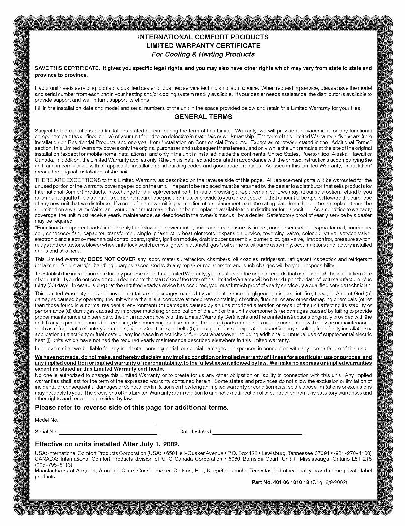
INTERNATIONAL COMFORT PRODUCTSLIMITED WARRANTY CERTIFICATE
For Cooling & Heating Products
SAVE THIS CERTIFICATE. It gives you specific legal rights, and you may also have other rights which may vary from state to state and
province to province.
If your unit needs servicing, contact a qualified dealer or qualified service technician of your choice. When requesting service, please have the modeland serial number from each unit in your heating and/or cooling system readily available. If your dealer needs assistance, the distributor is available toprovide support and we, in turn, support its efforts.
Fill in the installation date and model and serial numbers of the unit in the space provided below and retain this Limited Warranty for your files.
GENERAL TERMS
Subject to the conditions and limitations stated herein, during the term of this Limited Warranty, we will provide a replacement for any functionalcomponent part (as defined below) of your unit found to be defective in materials or workmanship. The term of this Limited Warranty is five years frominstallation on Residential Products and one year from installation on Commercial Products. Except as otherwise stated in the "Additional Terms"section, this Limited Warranty covers only the original purchaser and subsequent transferees, and only while the unit remains at the site of the originalinstallation (except for mobile home installations), and onty if the unit is installed inside the continental United States, Puerto Rico, Alaska, Hawaii orCanada. In addition, the Limited Warranty applies only if the unit is installed and operated in accordance with the printed instructions accompanying theunit, and in compliance with alt applicable installation and building codes and good trade practices. As used in this Limited Warranty, "installation"means the original installation of the unit.
TH ERE ARE EXCEPTIONS to this Limited Warranty as described on the reverse side of this page. All replacement parts will be warranted for theunused portion of the warranty coverage period on the unit. The part to be replaced must be returned by the dealer to a distributor that sells products forInternational Comfort Products, in exchange for the replacement part. In lieu of providing a replacement part, we may, at our sole option, refund to youan amount equal to the distributor's component purchase price from us, or provide to you a credit equal to that amount to be applied toward the purchaseof any new unit that we distribute. If a credit for a new unit is given in tieu of a replacement part, the rating plate from the unit being replaced must besubmitted on a warranty claim, and you r dealer must make the unit being replaced available to our distributor for disposition. As a condition to warrantycoverage, the unit must receive yearly maintenance, as described in the owner's manual, by a dealer. Satisfactory proof of yearly service by a dealermay be required."Functional component parts" include only the following: blower motor, unit-mounted sensors & timers, condenser motor, evaporator coil, condensercoil, condenser fan, capacitor, transformer, single-phase strip heat elements, expansion device, reversing valve, solenoid valve, service valve,electronic and electro-mechanical control board, ignitor, ignition module, draft inducer assembly, burner pilot, gas valve, limit control, pressure switch,relays and contactors, blower wheel, interlock switch, crosslighter, pilot shield, gas & oil burners, oil pump assembly, accumulators and factory installeddriers and strainers.
This Limited Warranty DOES NOT COVER any labor, material, refractory chambers, oii nozzles, refrigerant, refrigerant inspection and refrigerantreclaiming, freight and/or handling charges associated with any repair or replacement and such charges will be your responsibility.
Toestablish the installation date for any purpose under this Limited Warranty, you must retain the original records that can establish the installation dateofyour unit. Ifyou donot providesuchdocumentsthe start dateoftheterm ofthis LimitedWarrantywillbe based uponthedate ofunit manufacture, ptusthirty (30) days. In establishing that the required yearly service has occurred, you must furnish proof of yearly service by a qualified service technician.
This Limited Warranty does not cover: (a) failure or damages caused by accident, abuse, negligence, misuse, riot, fire, flood, or Acts of God (b)damages caused by operating the unit where there is a corrosive atmosphere containing chlorine, fluorine, or any other damaging chemicals (otherthan those found in a normal residential environment) (c) damages caused by an unauthorized alteration or repair of the unit affecting its stability orperformance (d) damages caused by improper matching or application of the unit or the unit's components (e) damages caused by failing to provideproper maintenance and service to the unit in accordance with this Limited Warranty Certificate and the printed instructions originally provided with theunit (f) any expenses incurred for erecting, disconnecting, or dismantling the unit (g) parts or supplies used in connection with service or maintenance,such as refrigerant, refractory chambers, oil nozzles, filters, or belts (h) damage, repairs, inoperation or inefficiency resulting from faulty installation orapplication (i) electricity or fuel costs or any increase in electricity or fuel cost whatsoever including additional or unusual use of supplemental electricheat (j) units which have not had the required yearly maintenance described elsewhere in this limited warranty.
In no event shall we be liable for any incidental, consequential, or special damages or expenses in connection with any use or failure of this unit.
We have not made. do not make. and hereby disclaim any implied condition or implied warranty of fitness for a particular use or purpose, andanv implied condition or implied warrantv of merchantabilitv, to the fu Ilest extent allowed bv law. We make no express or implied warrantiesexcept as stated in this Limited Warrantv certificate.
No one is authorized to change this Limited Warranty or to create for us any other obligation or liability in connection with this unit. Any impliedwarranties shall last for the term of the expressed warranty contained herein. Some states and provinces do not allow the exclusion or limitation ofincidental or consequential damages or do not allow limitations on how long an implied warranty or condition lasts, so the above limitations or exclusionsmay not apply to you. The provisions of this Limited Warranty are in addition to and not a modification of or subtraction from any statutory warranties andother rights and remedies provided by law.
Please refer to reverse side of this page for additional terms.
Model No.
Serial No. Date Installed
Effective on units installed After July 1, 2002,USA: International Comfort Products Corporation (USA) • 650 Hell-Quaker Avenue * P.O. Box 128 • Lewisburg, Tennessee 37091 • (931-270-4100)CANADA: International Comfort Products division of UTC Canada Corporation • 6060 Burnside Court, Unit 1, Mississauga, Ontario L5T 2T5(905-795-8113).Manufacturers of Airquest, Arcoaire, Clare, Comfortmaker, Dettson, Hell, Keeprite, Lincoln, Tempstar and other quality brand name private labelproducts.
Part No. 401 06 1010 18 (Orig. 8/9/2002)
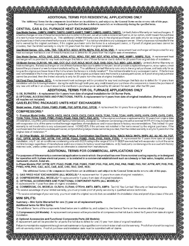
ADDITIONAL TERMS FOR RESIDENTIAL APPLICATIONS ONLY
The Additional Terms for the components listed below are in addition to, and subject to, the General Terms on the reverse side of this page.Warranty coverage is limited to parts that fail due to defect in materials or workmanship during the specified term.
CENTRAL GAS & OIL FURNACE HEAT EXCHANGERS*Gas Model Series: C9MPV. HgMPV. TgMPV. CgMPT. H9MPT. T9MPT. C9MPD. HgMPD. TgMPD: Limited Lifetime Warranty on heat exchangers. Ifa heat exchanger on one of these furnaces fails due to defect in the part, we will provide a replacement part or, at our option, credit toward the purchaseof a new furnace manufactured by us. This additional Limited Warranty runs only to the original purchaser, and tasts only for as tong as the originatpurchaser tives in the home where the furnace is initially installed.** It is not transferable to any subsequent owner. Ifthe furnace was not installed in thehome owned by the original purchaser, if the original purchaser setls the home to a subsequent owner, or if proof of originat purchase cannot beprovided, then the limited warranty is only for 20 years from the date of original installation.
Gas Model Series: GDL. GNL. TNE. TDE. NTC7. NDC7. NTP6. NDP6. TDE. NTV6. VNE: A replacement heat exchanger will be provided for anyheat exchanger that fails in one of these furnaces due to defect for 25 years from the originat date of installation.
Gas Model Series: NTC6. GNE. GDE. NDN6. NTG3. NDN3. FBF. NBF. NDF. NTN3. NTN6. NNE. N9MPI. N9MP2. FUH: A replacement heatexchanger witt be provided for any heat exchanger that faits in one of these furnaces due to defect for 20 years from original date of installation.
Oil Model Series: OLR(105, 160, 182), OCF, OLE OUF, NOLE NOUF, OLB, OHB, ODH, FLO, MBO, LBO, NOMF: Limited Lifetime Warranty onheat exchangers. Ifa heatexchangerononeofthesefurnacesfailsduetodefectinthepart, wewitl provide a replacement part or, at our option, credittoward the purchase of a new furnace manufactured by us. This additional Limited Warranty runs only to the original purchaser, and tasts only for aslong as the original purchaser lives in the home where the furnace is initially installed.** It is not transferable to any subsequent owner. If the furnacewas not installed in the home of the original purchaser, if the original purchaser sells the home to a subsequent owner, or if proof of original purchasecannot be provided, then the limited warranty is only for 20 years from the date of original installation.
Oil Fired Floor Furnace: NFO: A replacement heat exchanger witl be provided for any heat exchanger that faits due to defect for 10 years frominstallation with the following limitation: during the sixth through tenth year, any credit toward your purchase of a component or toward the purchase ofany new unit wilI be in an amount equal to the distributor's purchase price reduced by 20 percent for each year after the fifth year.
ADDITIONAL TERMS FOR OIL FURNACE APPLICATIONS ONLY1) OIL BURNERS - A replacement for 5 years from date of original installation for Oil Burner Parts.2) OPTIONAL ACCESSORIES AND FUNCTIONAL PARTS: A replacement for 5 years from date of original installation. (Refractory andoil nozzles not included)GAS/ELECTRIC PACKAGED UNITS HEAT EXCHANGERS
Model series: PGAD. PGAA. PGMD. PGME. PGF. GPFM. PGC. GPCM: A replacement for 10 years from original date of installation.
COMPRESSORS:*1) Premium Model Units: HAC0. HAC2. HAC4. CAC0. CAC2. CAC4. KAC0. TCA0. TCA2. TCA4. HHP0. HHP2. HHP4. CliP0. CliP2. CliP4.TCH0. TCH2. TCH4. PGME. PYMC. PHAD. PGAD. PA95. PAPC. PAK. APK: Tothe original purchaser a replacement for 10 years from original dateof installation, only if the unit is installed with factory matched coils, except air conditioner condensing units with a nominal SEER of 10 may be matchedwith evaporator coils of the same nominal tonnage regardless of manufacturer and in accordance to factory recommendations. This limited 10-yearwarranty is not transferable to any subsequent owner. HOWEVER, if the unit was not installed in the home owned by the original purchaser, if thepurchaser sells the home to a subsequent owner, or if proof of original purchase cannot be provided, then the limited warranty is only for 5 years from theoriginal date of installation.**
2) All Other Models: Air Conditioners. Heat PumPs. & Combination Gas/Electric Units: NAC0. NAC2. NHP0. NHP2. AO. A2. HO. H2. PGF.PGC, GPFM, GPCM, PAE APFM, PHE HPFM, PGAA, PGMD, PA55, PH55, PAPA, PYPA: A replacement for 5 years from date of originalinstallation, onty if: (a) air conditioner condensing units with SEER rating in the range of 10 to 11 SEER are matched with evaporator coils of the samenominal tonnage regardless of manufacturer and in accordance to factory recommendations, or (b) heat pump condensing units are used with factorymatched coils, unless written approval to do otherwise is obtained from manufacturer.
ADDITIONAL TERMS FOR COMMERCIAL APPLICATIONS ONLY
For purposes of this warranty a commercial application is one in which: the product has over 5 tons nominal cooling capacity, or is designedfor operation with 3 phase electrical power, or is installed in a commercial establishment such as a beauty or hair salon, hospital, school,restaurant, church, hotel etc..3-Phase Models: PGF, GPFM, GPF, PGAD, PGME, PGB, PGMG, PGMF, PGS, PGE, APE, PAE, PAB, PAMD, PAS, PAl=,APFM, APF, PHB, PHE,PYMD, HPB, PHS, CAC, ACC, CAE, ACE, CHC, HCC, CHE, HCE:
The additional Terms of the components listed below are in addition to and subject to the General Terms on the reverse side of this page.
1) GAS FIRED HEAT EXCHANGERS (ALL MODELS):* A replacement for 10 years from date of originat installation.2) COMPRESSORS (ALL MODELS):* A replacement for 5 years from date of original installation.3) OPTIONAL ACCESSORIES AND FUNCTIONAL COMPONENT PARTS (ALL MODELS):*A replacement for 1 year from date of original installation.4) COMMERCIAL OIL MODELS: OLR210, OLR350, OTF210, AMT3, AMT4, AMP3: Ten(10) Year Limited Warranty on heat exchangers.*To receive advantage of your limited warranty, you must provide proof of yearly service by a qualified service technician.
**To receive advantage of your warranty, you must retain the original records that can establish the installation date and proof of purchase of the unit.
MINI SPLITS:
Summary - Mini Splits Warranted for one (1) year on all replacement parts.Additional terms for Mini Splits:The additional Terms of the components listed below are in addition to, and subject to, the General Terms on the reverse side of this page.
1) Compressors (All Models): A replacement compressor wili be provided for atI compressors that faii due to defect for 5 years from date of originalinstallation.
2) Optional Accessories and Functional Components Parts (All Models):A replacement part will be provided for alt parts that fail due to defect for one (1) year from date of original installation.
Failu re to maintain the equipment through annual maintenance by a qualified service technician shall void the warranty. Proof of service wili be requiredwith ati warranty claims. Proof of purchase and installation date must be submitted with ali claims.