Embed Size (px)
Citation preview
INSTALLATION INSTRUCTIONS
Load classes to EN 1433
Typ I / Typ M nach EN 1433
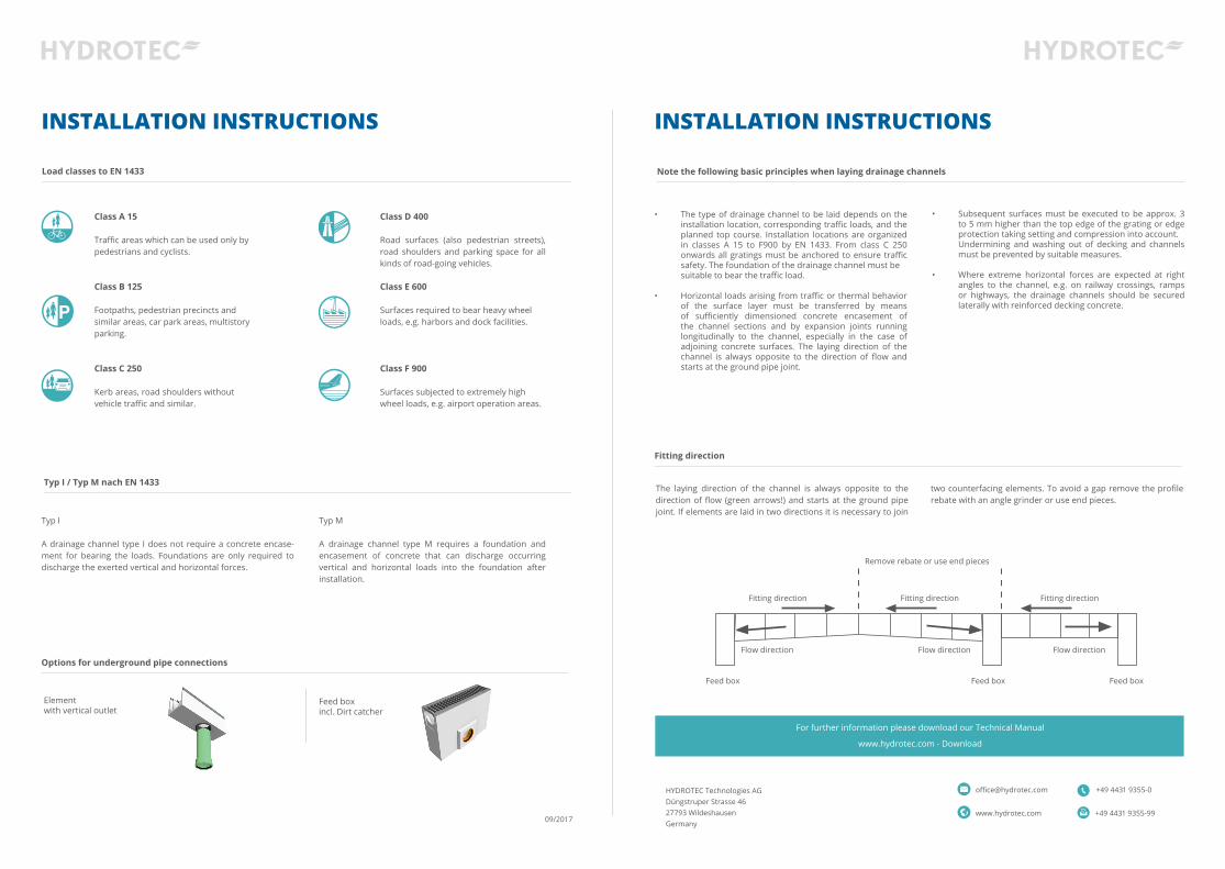
Fitting direction
Options for underground pipe connections
Class A 15
Traffic areas which can be used only bypedestrians and cyclists.
Class B 125
Footpaths, pedestrian precincts and similar areas, car park areas, multistory parking.
Class C 250
Kerb areas, road shoulders without vehicle traffic and similar.
Class D 400
Road surfaces (also pedestrian streets), road shoulders and parking space for all kinds of road-going vehicles.
Class E 600
Surfaces required to bear heavy wheel loads, e.g. harbors and dock facilities.
Class F 900
Surfaces subjected to extremely high wheel loads, e.g. airport operation areas.
Typ I
A drainage channel type I does not require a concrete encase-ment for bearing the loads. Foundations are only required to discharge the exerted vertical and horizontal forces.
The laying direction of the channel is always opposite to the direction of flow (green arrows!) and starts at the ground pipe joint. If elements are laid in two directions it is necessary to join
Elementwith vertical outlet
Feed boxincl. Dirt catcher
Typ M
A drainage channel type M requires a foundation and encasement of concrete that can discharge occurring vertical and horizontal loads into the foundation after installation.
Feed box Feed box Feed box
Flow direction Flow direction Flow direction
Remove rebate or use end pieces
Fitting direction Fitting directionFitting direction
two counterfacing elements. To avoid a gap remove the profile rebate with an angle grinder or use end pieces.
INSTALLATION INSTRUCTIONS
Note the following basic principles when laying drainage channels
• The type of drainage channel to be laid depends on the installation location, corresponding traffic loads, and the planned top course. Installation locations are organized in classes A 15 to F900 by EN 1433. From class C 250 onwards all gratings must be anchored to ensure traffic safety. The foundation of the drainage channel must be
suitable to bear the traffic load.
• Horizontal loads arising from traffic or thermal behavior of the surface layer must be transferred by means of sufficiently dimensioned concrete encasement of the channel sections and by expansion joints running longitudinally to the channel, especially in the case of adjoining concrete surfaces. The laying direction of the channel is always opposite to the direction of flow and starts at the ground pipe joint.
• Subsequent surfaces must be executed to be approx. 3 to 5 mm higher than the top edge of the grating or edge protection taking setting and compression into account.
Undermining and washing out of decking and channels must be prevented by suitable measures.
• Where extreme horizontal forces are expected at right
angles to the channel, e.g. on railway crossings, ramps or highways, the drainage channels should be secured laterally with reinforced decking concrete.
HYDROTEC Technologies AGDüngstruper Strasse 46 27793 WildeshausenGermany
+49 4431 [email protected]
www.hydrotec.com +49 4431 9355-99
For further information please download our Technical Manual
www.hydrotec.com - Download
09/2017
Frost-proofload bearing substructure
INSTALLATION INSTRUCTIONS
Paving
Decking
Expansion joint
Paving (grouting)
Load bearing substructure
Concrete
Pavement
Sand
Gravel
Curb
Concrete
Paving
Expansion joint
Paving (grouting)
Load bearing substructure
Concrete
Paving
Paving (grouting)
Load bearing substructure
Frost-proofload bearing substructure
Concrete
Paving
Paving
Top course Top course
Paving (grouting)
Paving (grouting)
Binder course Binder course
Load bearing substructure
Load bearing substructure
Base course Load bearing substructure
Concrete
Concrete
Concrete Installation support
Concrete
INSTALLATION INSTRUCTIONS
Expansion joint
Frost-proofload bearing substructure
Frost-proofload bearing substructure
Frost-proofload bearing substructure
Frost-proofload bearing substructure
Frost-proofload bearing substructure
Frost-proofload bearing substructure
x (according to calculation)
A 15 B 125 / C 250
10 cm Concrete C25/3015 cm Concrete C25/30
y (according to calculation)
A 15 B 125 / C 250
10 cm Concrete C25/3015 cm Concrete C25/30
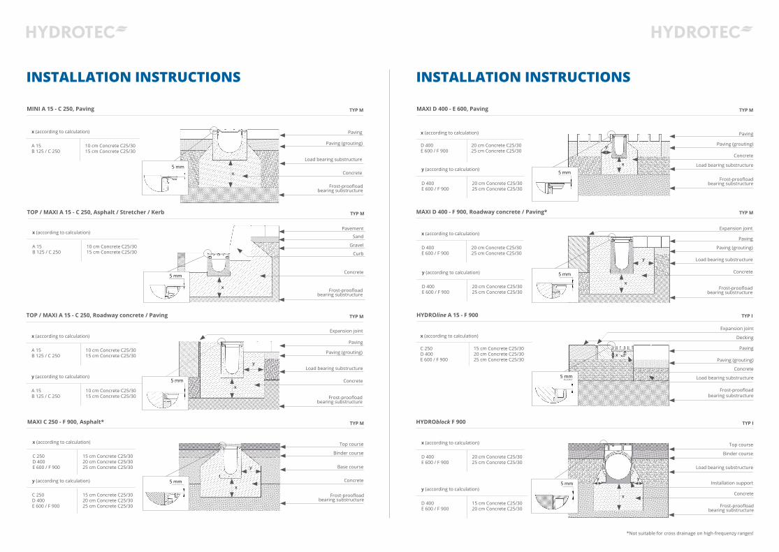
MINI A 15 - C 250, Paving
HYDROline A 15 - F 900
TOP / MAXI A 15 - C 250, Asphalt / Stretcher / Kerb
TOP / MAXI A 15 - C 250, Roadway concrete / Paving
x
x
x (according to calculation)
C 250 D 400E 600 / F 900
15 cm Concrete C25/3020 cm Concrete C25/3025 cm Concrete C25/30
x (according to calculation)
A 15 B 125 / C 250
10 cm Concrete C25/3015 cm Concrete C25/30
x
y
x
x (according to calculation)
A 15 B 125 / C 250
10 cm Concrete C25/3015 cm Concrete C25/30
x (according to calculation)
D 400 E 600 / F 900
20 cm Concrete C25/3025 cm Concrete C25/30
y (according to calculation)
D 400 E 600 / F 900
15 cm Concrete C25/3020 cm Concrete C25/30
MAXI D 400 - E 600, Paving
MAXI D 400 - F 900, Roadway concrete / Paving*
MAXI C 250 - F 900, Asphalt* HYDROblock F 900
x (according to calculation)
D 400E 600 / F 900
20 cm Concrete C25/3025 cm Concrete C25/30
x (according to calculation)
D 400E 600 / F 900
20 cm Concrete C25/3025 cm Concrete C25/30
y (according to calculation)
D 400E 600 / F 900
20 cm Concrete C25/3025 cm Concrete C25/30
x (according to calculation)
C 250D 400E 600 / F 900
15 cm Concrete C25/3020 cm Concrete C25/3025 cm Concrete C25/30
y (according to calculation)
C 250D 400E 600 / F 900
15 cm Concrete C25/3020 cm Concrete C25/3025 cm Concrete C25/30
y (according to calculation)
D 400E 600 / F 900
20 cm Concrete C25/3025 cm Concrete C25/30
x
x
x
x
y
y
y
y y
*Not suitable for cross drainage on high-frequenzy ranges!
5 mm
5 mm
5 mm
5 mm
5 mm
5 mm
5 mm 5 mm
TYP M
TYP I
TYP M
TYP M
TYP M
TYP M
TYP M TYP I