Embed Size (px)
Citation preview
1 of 56
Form 6423-T, 07-12Supersedes Form 6423-T, 05-12d
INSTALLATION INSTRUCTIONS FOR ROAd FORCe TOUCh® / GSP9700 SeRIeS BALANCeRS
Installation of a Road Force Touch® / GSP9700 Series Balancer should be completed only by an authorized Hunter Service Representative.
This document provides the information needed to install a Road Force Touch® / GSP9700 Series Balancer.
PLACemeNT
The balancer should be placed in a dry area that is not subject to moisture. Clearance for the operator at the front and to the right of the balancer should be at least 3 feet (0.91 meter). There must also be ample clearance at the rear of the balancer to allow the safety hood to open fully. The electrical power cord should be positioned so that it cannot be walked on, driven over, or tripped over.
FLOOR ReqUIRemeNTS
The balancer should be placed on a solid concrete floor. Any floor condition, which might allow the balancer to move during operation, is unacceptable.
If the location selected is a hard surface floor that is hollow underneath, place the balancer over a supporting beam or close to a supporting wall.
POweR ReqUIRemeNTS
The customer must furnish a 230VAC +10% / -15%, 10 amp 50/60 Hz single-phase electrical supply for the balancer. This machine must be connected to a 20 Amp branch circuit. Please refer all power source issues to a certified electrician.
The power cord supplied utilizes a twist lock connector, NEMA L6-20P. The power cord may need modified to match the available electrical receptacle for your region. For instructions to replace the single-phase power plug with a three-phase NEMA L15-20P power plug refer to form 5350T. Changes to the electrical power cord, plug, and/or power source must be performed by a certified electrician in accordance with local electrical codes.
Figure 1
PNeUmATIC ReqUIRemeNTS
The customer must provide a low-pressure air supply (between 100-175 psi (6.9–12.0 bar)). Necessary for balancers equipped with the Auto-Clamp and Inflation Station. A moisture trap and/or filter is necessary to provide clean, dry air.
2
SPeCIAL TOOLS ReqUIRed• Silicone or Teflon Grease
• Calibration Tool, 221-672-1 (for Dataset® Arms)
• Collet (or cone), 1 1/4 inch open-ended wrench and a 3/8-16 X 2 1/2 inch (or longer) bolt (the 3/8 inch diameter and 16 threads per inch is required) (for spindle installation)
• Torque wrench
The accessories kit contains hardware and loose components that are required to complete the installation of the balancer.
BASe PLACemeNT
1. Pre-determine a location with the proper floor surface, space, and electrical requirements as stated above where the balancer will be used.
2. Remove loose components from base assembly and set aside
3. Remove exterior packaging and inspect components.
4. Cut away plastic wrap and packing material. .
Balancers with the optional wheel lift may have a bolt anchoring the balancer to the pallet located under the wheel lift mechanism.
5. Remove tie strap to free hood bar.
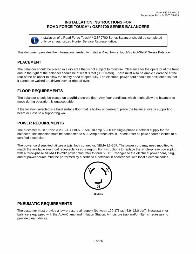
6. Remove the bolts and hold-down brackets securing the base assembly to the pallet.
Figure 2
Retain the hold-down brackets if balancer is to be secured to the floor. The brackets are used for both shipping and installation.
7. Remove the base assembly from the pallet.
Use proper lifting techniques when moving the base assembly. Do NOT lift by weight tray. Two or more people recommended.
3
8. Position the base near the intended location. Refer to “Placement,” on page 1 for detailed instructions.
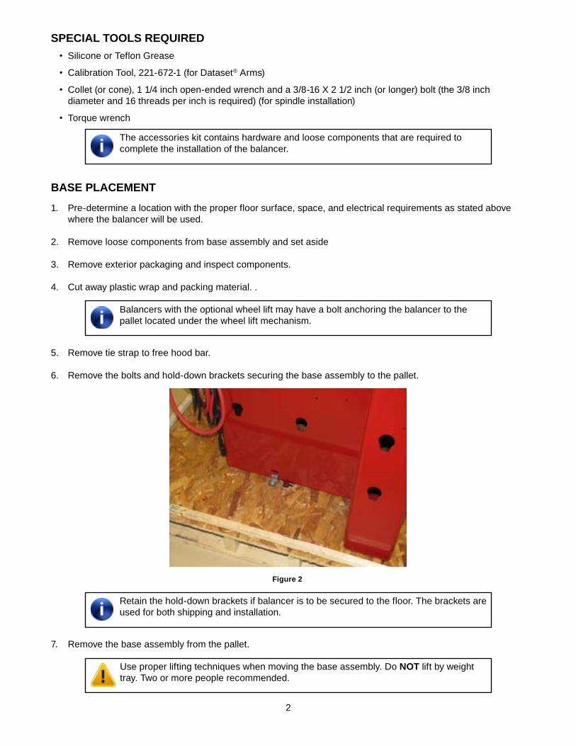
IF APPLICABLe, RemOVe The ShIPPING BOLT FROm The VIBRATION STRUCTURe
1. Locate the shipping bolt, identified by the yellow tag, on the front of the balancer.
RemOVe
Figure 3
2. Remove and discard the shipping bolt.
RemOVe weIGhT TRAY
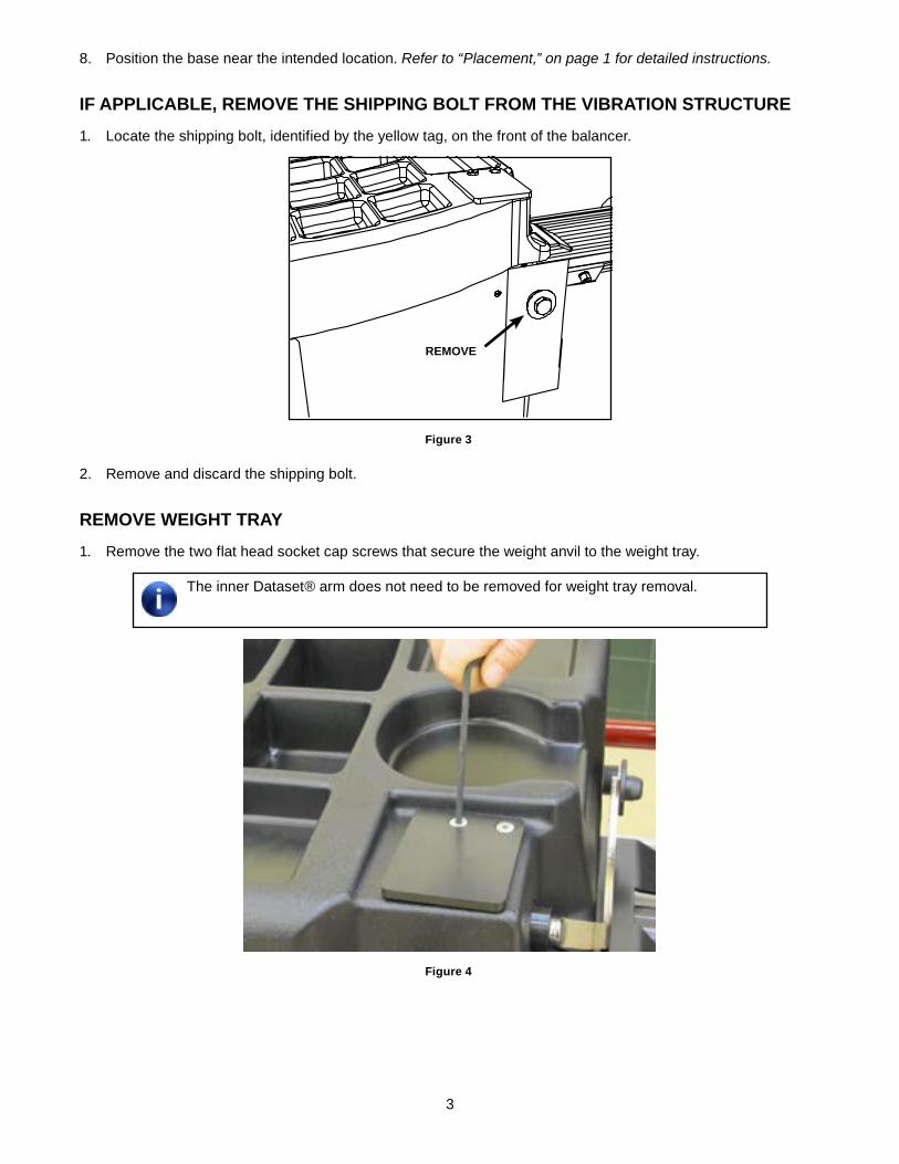
1. Remove the two flat head socket cap screws that secure the weight anvil to the weight tray.
The inner Dataset® arm does not need to be removed for weight tray removal.
Figure 4

4
2. Pull the inner Dataset arm out and hook it on the opposite side of the spindle face so it does not interfere with weight tray removal.
Figure 5
3. Lift the rear of the weight tray up, slide to the right, and forward off the base. Set the weight tray aside.
Figure 6
5
4. Remove rust-preventative paper from within balancer tub. During assembly of balancer, route all external wires and air lines (if present) through the hole located in back of balancer.
Figure 7
INSTALL dISPLAY SUPPORT ASSemBLY ANd LCd mONITOR
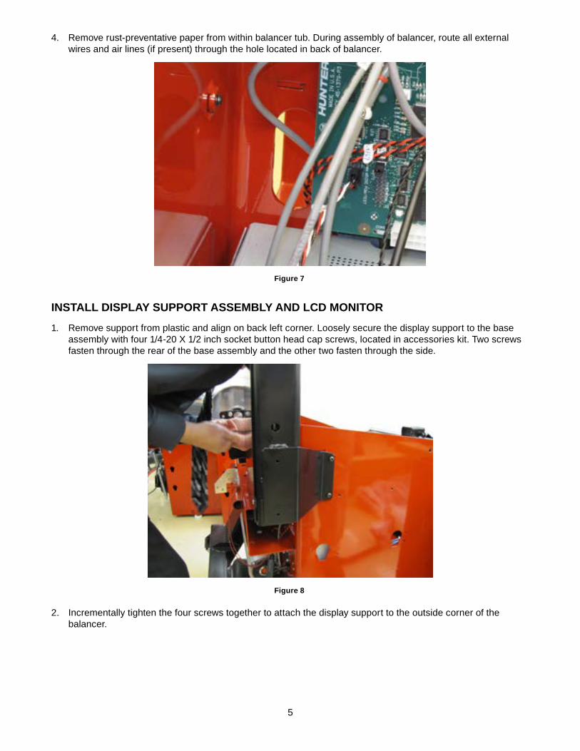
1. Remove support from plastic and align on back left corner. Loosely secure the display support to the base assembly with four 1/4-20 X 1/2 inch socket button head cap screws, located in accessories kit. Two screws fasten through the rear of the base assembly and the other two fasten through the side.
Figure 8
2. Incrementally tighten the four screws together to attach the display support to the outside corner of the balancer.
6
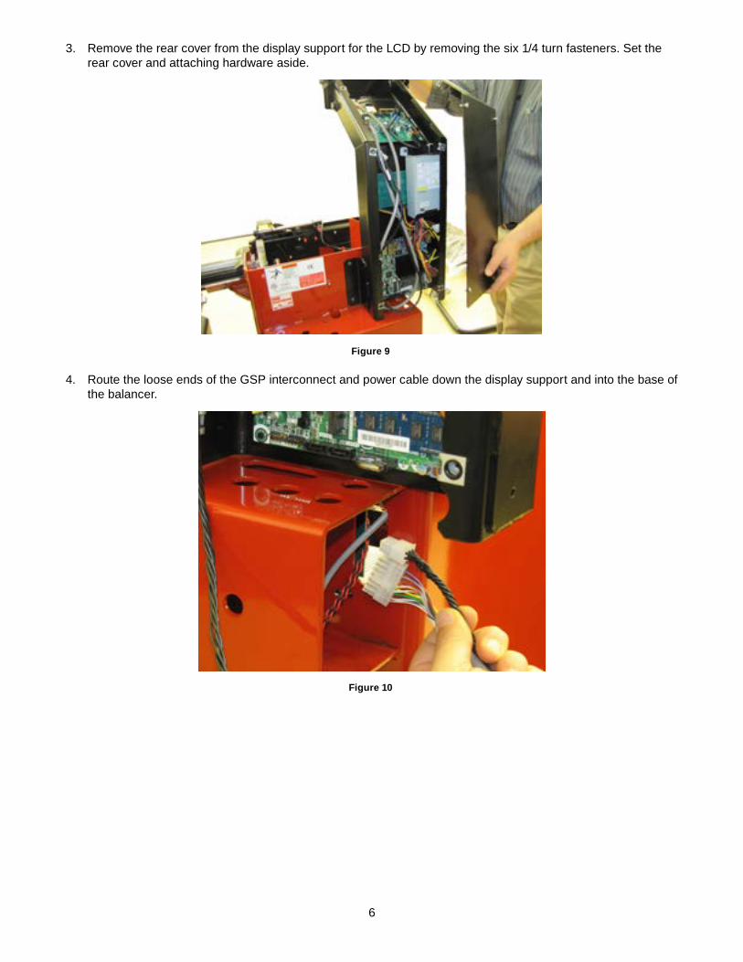
3. Remove the rear cover from the display support for the LCD by removing the six 1/4 turn fasteners. Set the rear cover and attaching hardware aside.
Figure 9
4. Route the loose ends of the GSP interconnect and power cable down the display support and into the base of the balancer.
Figure 10
7
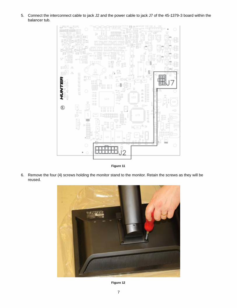
5. Connect the interconnect cable to jack J2 and the power cable to jack J7 of the 45-1379-3 board within the balancer tub.
Figure 11
6. Remove the four (4) screws holding the monitor stand to the monitor. Retain the screws as they will be reused.
Figure 12
8
HP monitors will require all four retained screws. Planar monitors will require two of the supplied screws and two 75-659-2 screws (supplied in accessories kit). If needed, instructions to remove the planar stand are included with the monitor.
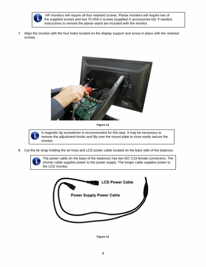
7. Align the monitor with the four holes located on the display support and screw in place with the retained screws.
Figure 13
A magnetic tip screwdriver is recommended for this step. It may be necessary to remove the adjustment knobs and flip over the mount plate to more easily secure the monitor.
8. Cut the tie strap holding the air hose and LCD power cable located on the back side of the balancer.
The power cable (in the base of the balancer) has two IEC C13 female connectors. The shorter cable supplies power to the power supply. The longer cable supplies power to the LCD monitor.
Figure 14
9
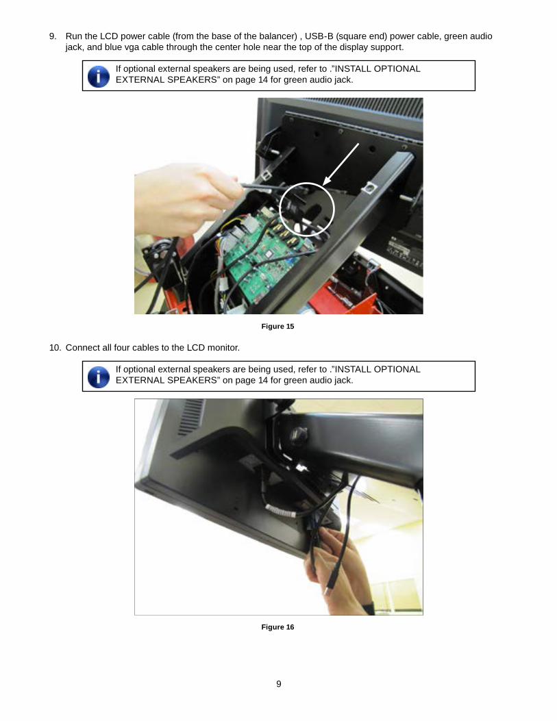
9. Run the LCD power cable (from the base of the balancer) , USB-B (square end) power cable, green audio jack, and blue vga cable through the center hole near the top of the display support.
If optional external speakers are being used, refer to .”INSTALL OPTIONAL EXTERNAL SPEAKERS” on page 14 for green audio jack.
Figure 15
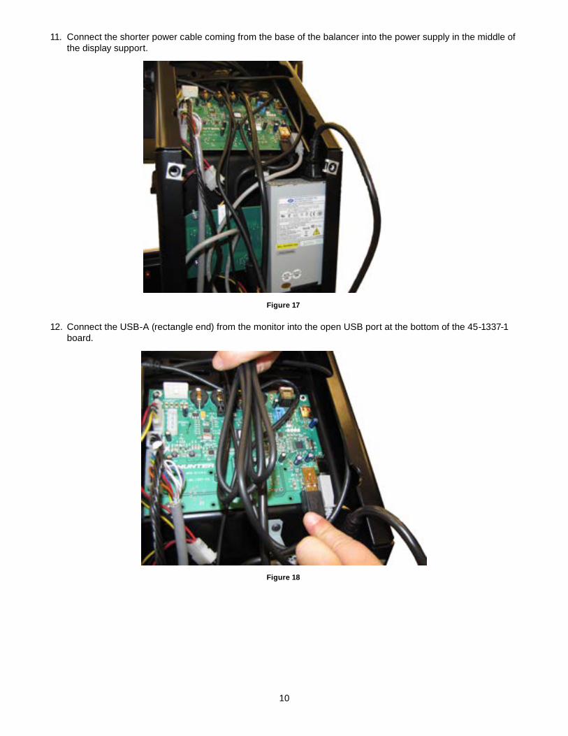
10. Connect all four cables to the LCD monitor.
If optional external speakers are being used, refer to .”INSTALL OPTIONAL EXTERNAL SPEAKERS” on page 14 for green audio jack.
Figure 16
10
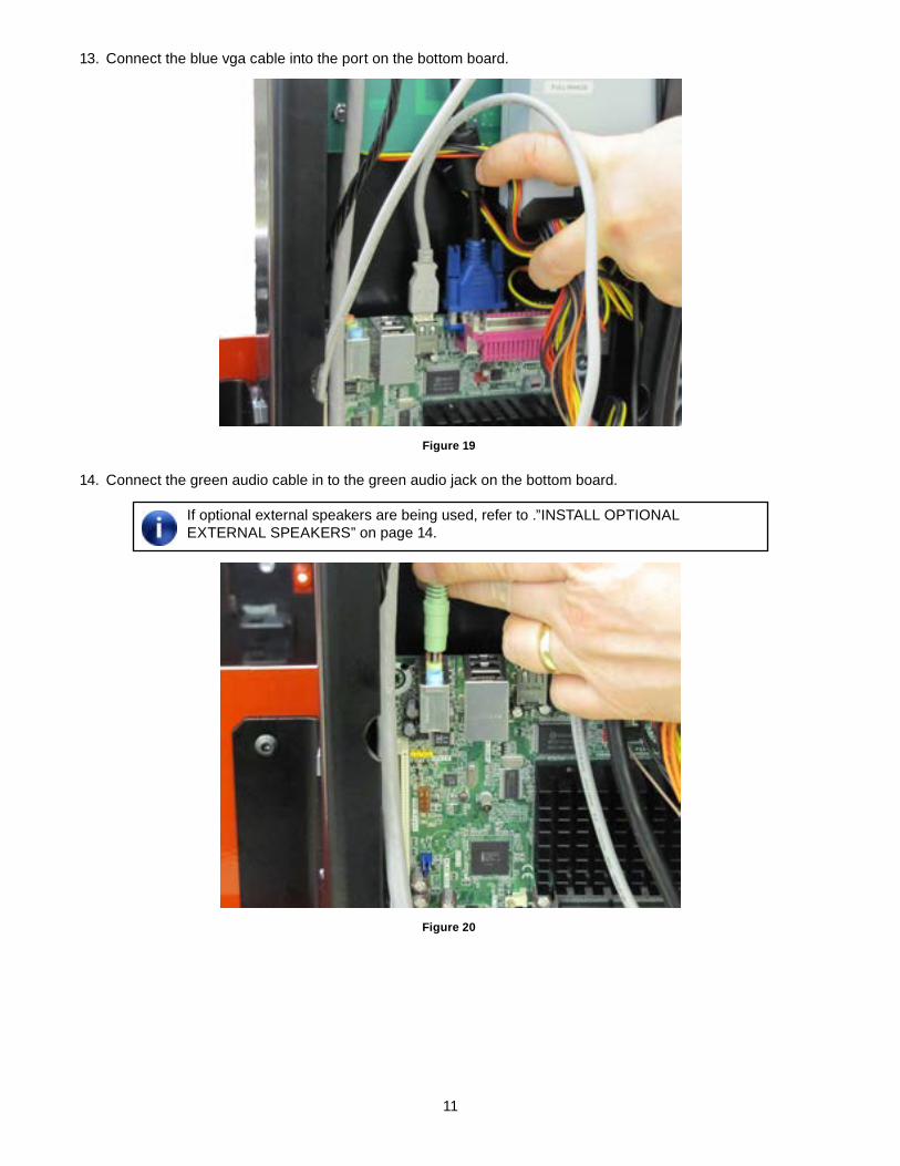
11. Connect the shorter power cable coming from the base of the balancer into the power supply in the middle of the display support.
Figure 17
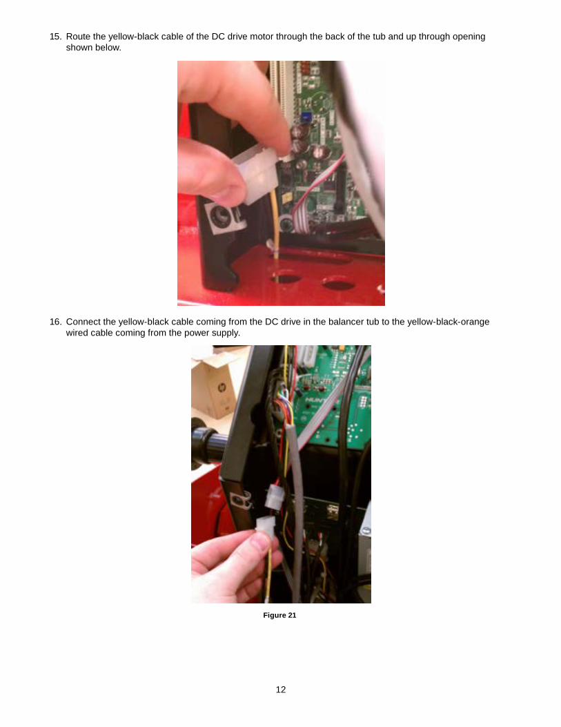
12. Connect the USB-A (rectangle end) from the monitor into the open USB port at the bottom of the 45-1337-1 board.
Figure 18
11
13. Connect the blue vga cable into the port on the bottom board.
Figure 19
14. Connect the green audio cable in to the green audio jack on the bottom board.
If optional external speakers are being used, refer to .”INSTALL OPTIONAL EXTERNAL SPEAKERS” on page 14.
Figure 20
12
15. Route the yellow-black cable of the DC drive motor through the back of the tub and up through opening shown below.
16. Connect the yellow-black cable coming from the DC drive in the balancer tub to the yellow-black-orange wired cable coming from the power supply.
Figure 21
13
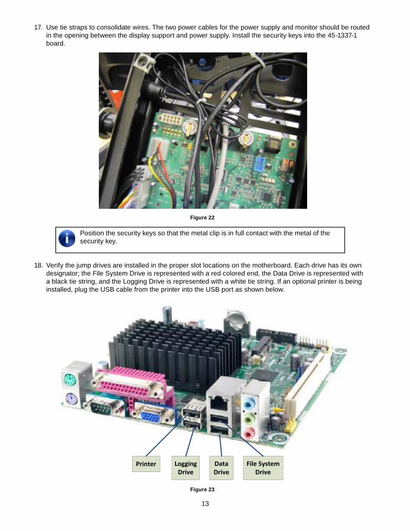
17. Use tie straps to consolidate wires. The two power cables for the power supply and monitor should be routed in the opening between the display support and power supply. Install the security keys into the 45-1337-1 board.
Figure 22
Position the security keys so that the metal clip is in full contact with the metal of the security key.
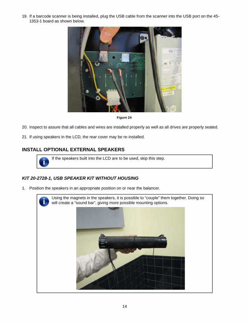
18. Verify the jump drives are installed in the proper slot locations on the motherboard. Each drive has its own designator; the File System Drive is represented with a red colored end, the Data Drive is represented with a black tie string, and the Logging Drive is represented with a white tie string. If an optional printer is being installed, plug the USB cable from the printer into the USB port as shown below.
Printer LoggingDrive
DataDrive
File SystemDrive
Figure 23
14
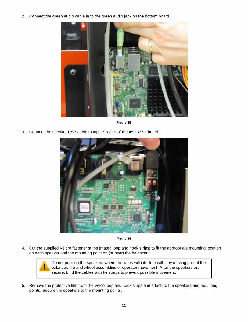
19. If a barcode scanner is being installed, plug the USB cable from the scanner into the USB port on the 45-1353-1 board as shown below.
Figure 24
20. Inspect to assure that all cables and wires are installed properly as well as all drives are properly seated.
21. If using speakers in the LCD, the rear cover may be re-installed.
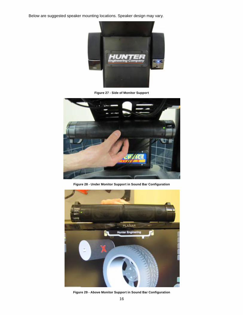
INSTALL OPTIONAL eXTeRNAL SPeAKeRSIf the speakers built into the LCD are to be used, skip this step.
Kit 20-2728-1, USB SpeaKer Kit withoUt hoUSing
1. Position the speakers in an appropriate position on or near the balancer.
Using the magnets in the speakers, it is possible to “couple” them together. Doing so will create a “sound bar”, giving more possible mounting options.
15
2. Connect the green audio cable in to the green audio jack on the bottom board.
Figure 25
3. Connect the speaker USB cable to top USB port of the 45-1337-1 board.
Figure 26
4. Cut the supplied Velcro fastener strips (mated loop and hook strips) to fit the appropriate mounting location on each speaker and the mounting point on (or near) the balancer.
Do not position the speakers where the wires will interfere with any moving part of the balancer, tire and wheel assemblies or operator movement. After the speakers are secure, bind the cables with tie straps to prevent possible movement.
5. Remove the protective film from the Velco loop and hook strips and attach to the speakers and mounting points. Secure the speakers to the mounting points.
16
Below are suggested speaker mounting locations. Speaker design may vary.
Figure 27 - Side of monitor Support
Figure 28 - Under monitor Support in Sound Bar Configuration
Figure 29 - Above monitor Support in Sound Bar Configuration
17
6. Install the monitor support cover, making sure none of the wires are pinched.
Kit 20-2529-1, USB SpeaKer Kit with hoUSing
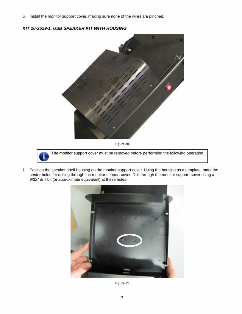
Figure 30
The monitor support cover must be removed before performing the following operation.
1. Position the speaker shelf housing on the monitor support cover. Using the housing as a template, mark the center holes for drilling through the monitor support cover. Drill through the monitor support cover using a 9/32” drill bit (or approximate equivalent) at these holes.
Figure 31
18
2. Secure the speaker shelf housing to the monitor support cover using two 1/4-20 x .50 socket button head cap screws, 75-481-2, and two 1/4-20 Keps nuts, 76-85-2.
3. Enlarge one of the other holes in the speaker shelf housing to accommodate the USB connector on the speakers. Drill through the monitor support cover at this location also.
4. Route the speaker wires through the speaker shelf housing and the monitor support cover.
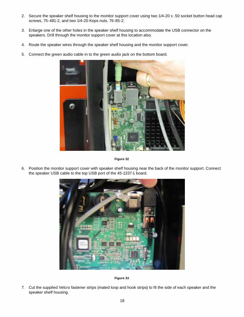
5. Connect the green audio cable in to the green audio jack on the bottom board.
Figure 32
6. Position the monitor support cover with speaker shelf housing near the back of the monitor support. Connect the speaker USB cable to the top USB port of the 45-1337-1 board.
Figure 33
7. Cut the supplied Velcro fastener strips (mated loop and hook strips) to fit the side of each speaker and the speaker shelf housing.
19
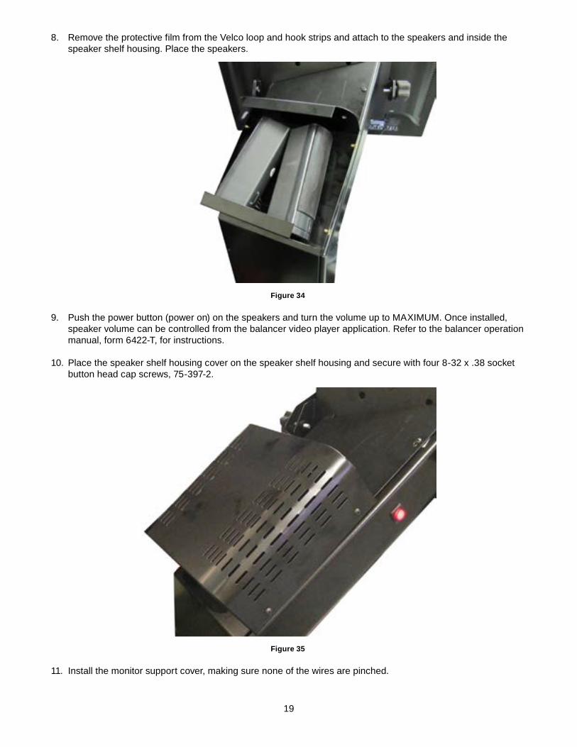
8. Remove the protective film from the Velco loop and hook strips and attach to the speakers and inside the speaker shelf housing. Place the speakers.
Figure 34
9. Push the power button (power on) on the speakers and turn the volume up to MAXIMUM. Once installed, speaker volume can be controlled from the balancer video player application. Refer to the balancer operation manual, form 6422-T, for instructions.
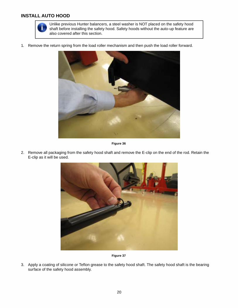
10. Place the speaker shelf housing cover on the speaker shelf housing and secure with four 8-32 x .38 socket button head cap screws, 75-397-2.
Figure 35
11. Install the monitor support cover, making sure none of the wires are pinched.
20
INSTALL AUTO hOOdUnlike previous Hunter balancers, a steel washer is NOT placed on the safety hood shaft before installing the safety hood. Safety hoods without the auto-up feature are also covered after this section.
1. Remove the return spring from the load roller mechanism and then push the load roller forward.
Figure 36
2. Remove all packaging from the safety hood shaft and remove the E-clip on the end of the rod. Retain the E-clip as it will be used.
Figure 37
3. Apply a coating of silicone or Teflon grease to the safety hood shaft. The safety hood shaft is the bearing surface of the safety hood assembly.
21
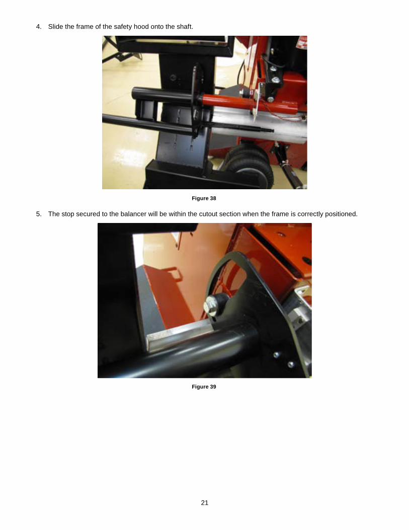
4. Slide the frame of the safety hood onto the shaft.
Figure 38
5. The stop secured to the balancer will be within the cutout section when the frame is correctly positioned.
Figure 39
22
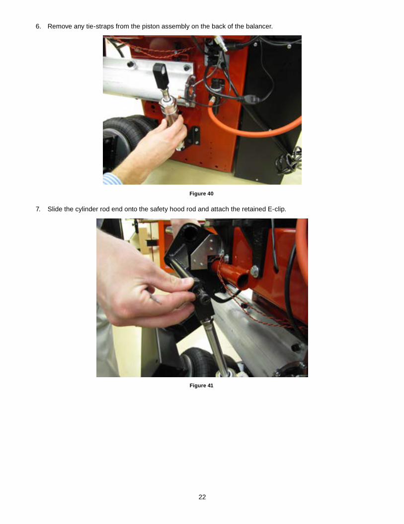
6. Remove any tie-straps from the piston assembly on the back of the balancer.
Figure 40
7. Slide the cylinder rod end onto the safety hood rod and attach the retained E-clip.
Figure 41
23
hOOd STOP AdjUSTmeNT
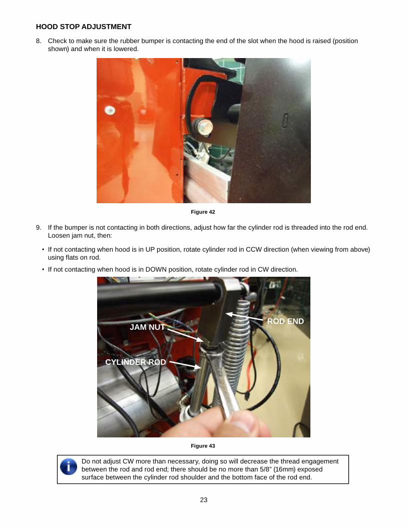
8. Check to make sure the rubber bumper is contacting the end of the slot when the hood is raised (position shown) and when it is lowered.
Figure 42
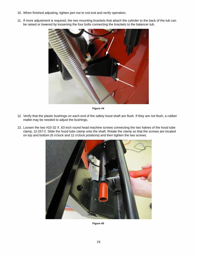
9. If the bumper is not contacting in both directions, adjust how far the cylinder rod is threaded into the rod end. Loosen jam nut, then:
• If not contacting when hood is in UP position, rotate cylinder rod in CCW direction (when viewing from above) using flats on rod.
• If not contacting when hood is in DOWN position, rotate cylinder rod in CW direction.
Figure 43
Do not adjust CW more than necessary, doing so will decrease the thread engagement between the rod and rod end; there should be no more than 5/8” (16mm) exposed surface between the cylinder rod shoulder and the bottom face of the rod end.
jAm NUTROd eNd
CYLINdeR ROd
24
10. When finished adjusting, tighten jam nut to rod end and verify operation.
11. If more adjustment is required, the two mounting brackets that attach the cylinder to the back of the tub can be raised or lowered by loosening the four bolts connecting the brackets to the balancer tub.
Figure 44
12. Verify that the plastic bushings on each end of the safety hood shaft are flush. If they are not flush, a rubber mallet may be needed to adjust the bushings.
13. Loosen the two #10-32 X .63 inch round head machine screws connecting the two halves of the hood tube clamp, 12-157-2. Slide the hood tube clamp onto the shaft. Rotate the clamp so that the screws are located on top and bottom (6 o’clock and 12 o’clock positions) and then tighten the two screws.
Figure 45
25
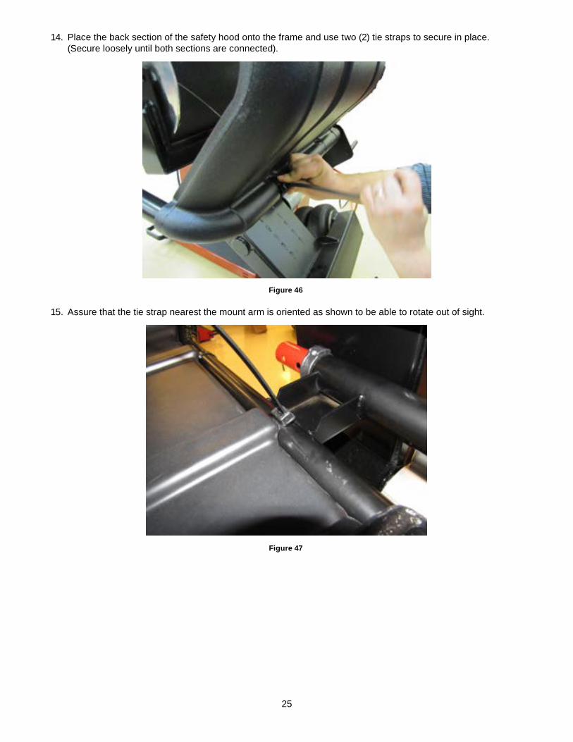
14. Place the back section of the safety hood onto the frame and use two (2) tie straps to secure in place. (Secure loosely until both sections are connected).
Figure 46
15. Assure that the tie strap nearest the mount arm is oriented as shown to be able to rotate out of sight.
Figure 47
26
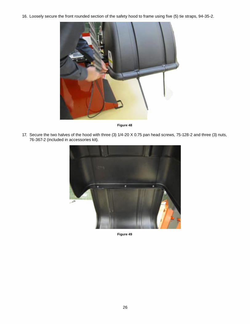
16. Loosely secure the front rounded section of the safety hood to frame using five (5) tie straps, 94-35-2.
Figure 48
17. Secure the two halves of the hood with three (3) 1/4-20 X 0.75 pan head screws, 75-128-2 and three (3) nuts, 76-367-2 (included in accessories kit).
Figure 49
27
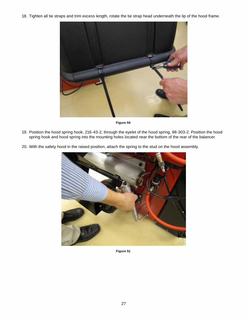
18. Tighten all tie straps and trim excess length, rotate the tie strap head underneath the lip of the hood frame.
Figure 50
19. Position the hood spring hook, 216-43-2, through the eyelet of the hood spring, 98-303-2. Position the hood spring hook and hood spring into the mounting holes located near the bottom of the rear of the balancer.
20. With the safety hood in the raised position, attach the spring to the stud on the hood assembly.
Figure 51
28
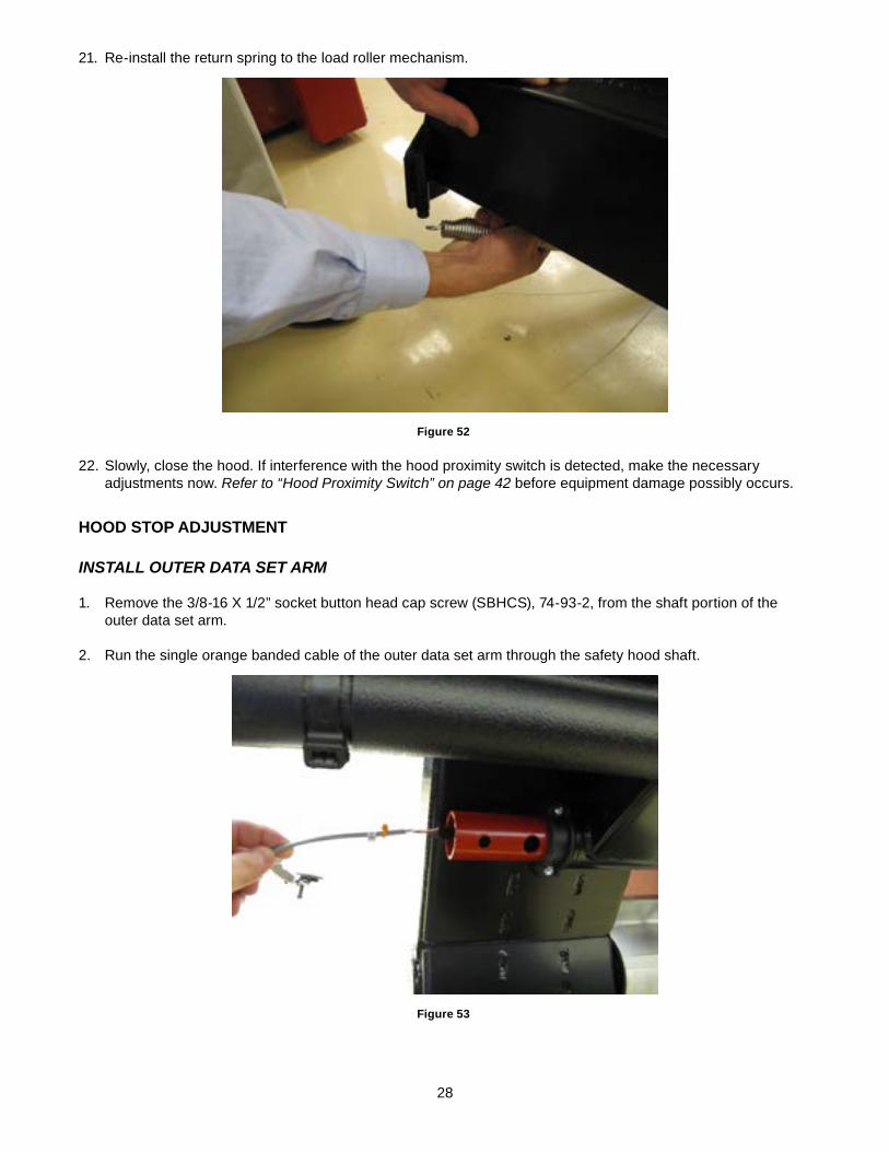
21. Re-install the return spring to the load roller mechanism.
Figure 52
22. Slowly, close the hood. If interference with the hood proximity switch is detected, make the necessary adjustments now. Refer to “Hood Proximity Switch” on page 42 before equipment damage possibly occurs.
hOOd STOP AdjUSTmeNT
inStall oUter Data Set arm
1. Remove the 3/8-16 X 1/2” socket button head cap screw (SBHCS), 74-93-2, from the shaft portion of the outer data set arm.
2. Run the single orange banded cable of the outer data set arm through the safety hood shaft.
Figure 53
29
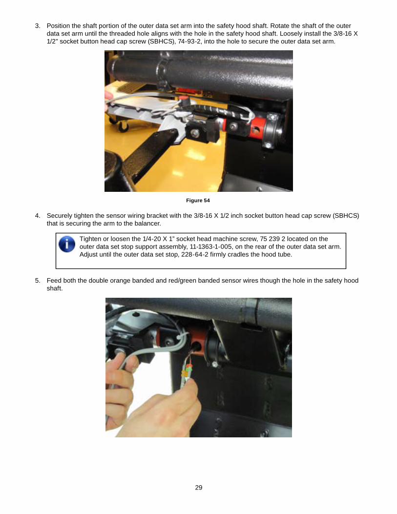
3. Position the shaft portion of the outer data set arm into the safety hood shaft. Rotate the shaft of the outer data set arm until the threaded hole aligns with the hole in the safety hood shaft. Loosely install the 3/8-16 X 1/2” socket button head cap screw (SBHCS), 74-93-2, into the hole to secure the outer data set arm.
Figure 54
4. Securely tighten the sensor wiring bracket with the 3/8-16 X 1/2 inch socket button head cap screw (SBHCS) that is securing the arm to the balancer.
Tighten or loosen the 1/4-20 X 1” socket head machine screw, 75 239 2 located on the outer data set stop support assembly, 11-1363-1-005, on the rear of the outer data set arm. Adjust until the outer data set stop, 228-64-2 firmly cradles the hood tube.
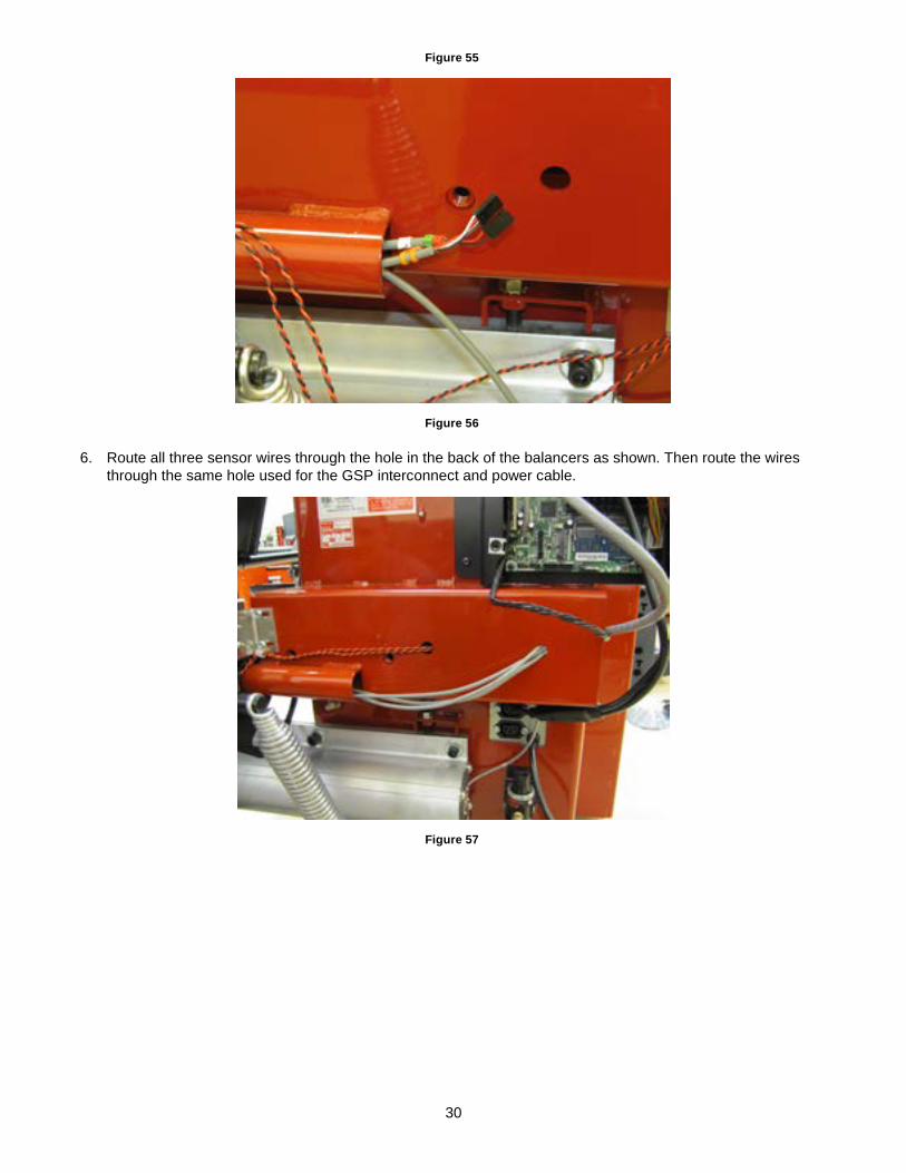
5. Feed both the double orange banded and red/green banded sensor wires though the hole in the safety hood shaft.
30
Figure 55
Figure 56
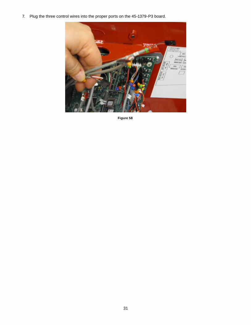
6. Route all three sensor wires through the hole in the back of the balancers as shown. Then route the wires through the same hole used for the GSP interconnect and power cable.
Figure 57
31
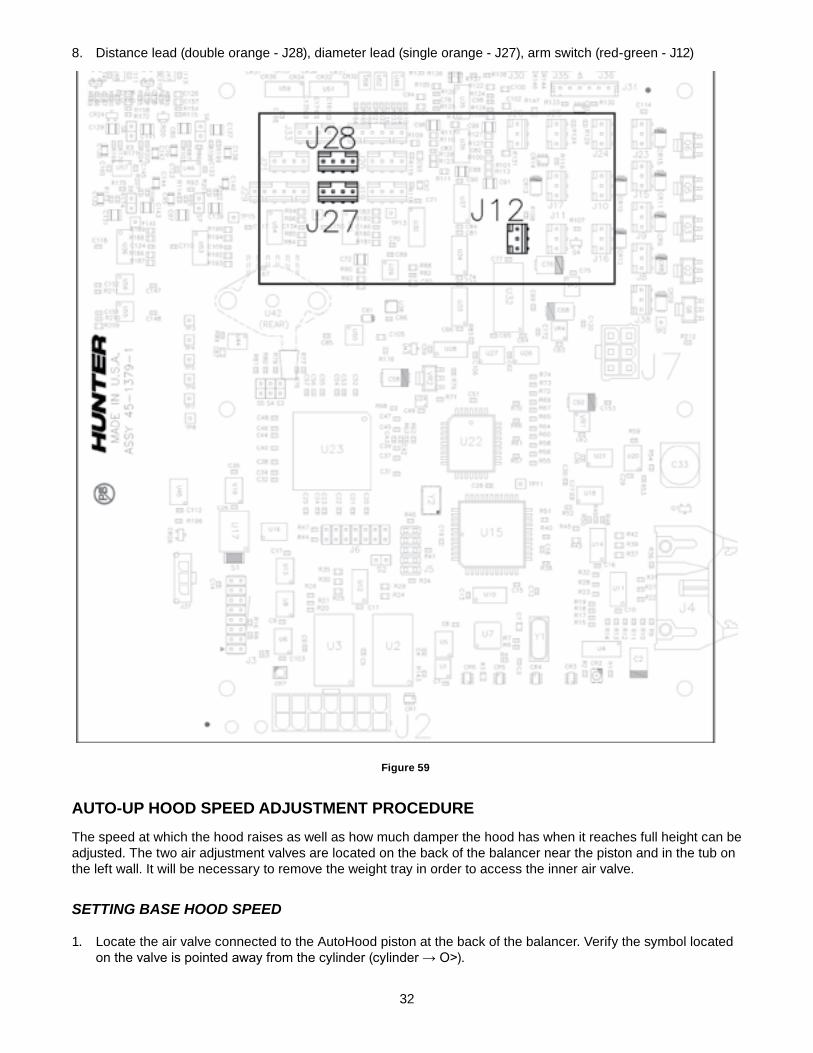
7. Plug the three control wires into the proper ports on the 45-1379-P3 board.
Figure 58
32
8. Distance lead (double orange - J28), diameter lead (single orange - J27), arm switch (red-green - J12)
Figure 59
AUTO-UP hOOd SPeed AdjUSTmeNT PROCedURe
The speed at which the hood raises as well as how much damper the hood has when it reaches full height can be adjusted. The two air adjustment valves are located on the back of the balancer near the piston and in the tub on the left wall. It will be necessary to remove the weight tray in order to access the inner air valve.
Setting BaSe hooD SpeeD
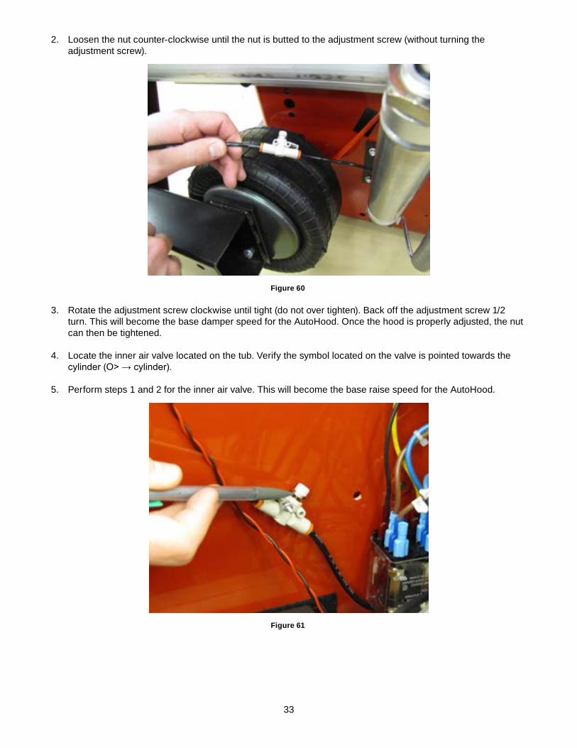
1. Locate the air valve connected to the AutoHood piston at the back of the balancer. Verify the symbol located onthevalveispointedawayfromthecylinder(cylinder→O>).
33
2. Loosen the nut counter-clockwise until the nut is butted to the adjustment screw (without turning the adjustment screw).
Figure 60
3. Rotate the adjustment screw clockwise until tight (do not over tighten). Back off the adjustment screw 1/2 turn. This will become the base damper speed for the AutoHood. Once the hood is properly adjusted, the nut can then be tightened.
4. Locate the inner air valve located on the tub. Verify the symbol located on the valve is pointed towards the cylinder(O>→cylinder).
5. Perform steps 1 and 2 for the inner air valve. This will become the base raise speed for the AutoHood.
Figure 61
34
Final aDjUStmentS
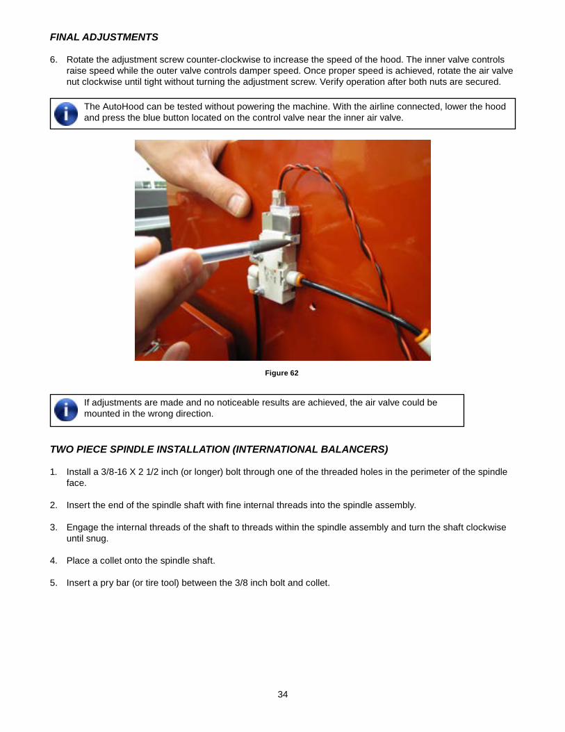
6. Rotate the adjustment screw counter-clockwise to increase the speed of the hood. The inner valve controls raise speed while the outer valve controls damper speed. Once proper speed is achieved, rotate the air valve nut clockwise until tight without turning the adjustment screw. Verify operation after both nuts are secured.
The AutoHood can be tested without powering the machine. With the airline connected, lower the hood and press the blue button located on the control valve near the inner air valve.
Figure 62
If adjustments are made and no noticeable results are achieved, the air valve could be mounted in the wrong direction.
two pieCe SpinDle inStallation (international BalanCerS)
1. Install a 3/8-16 X 2 1/2 inch (or longer) bolt through one of the threaded holes in the perimeter of the spindle face.
2. Insert the end of the spindle shaft with fine internal threads into the spindle assembly.
3. Engage the internal threads of the shaft to threads within the spindle assembly and turn the shaft clockwise until snug.
4. Place a collet onto the spindle shaft.
5. Insert a pry bar (or tire tool) between the 3/8 inch bolt and collet.
35
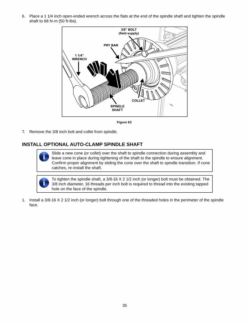
6. Place a 1 1/4 inch open-ended wrench across the flats at the end of the spindle shaft and tighten the spindle shaft to 68 N-m (50 ft-lbs).
3/8” BOLT(field supply)
PRY BAR
COLLET
SPINDLESHAFT
1 1/4”WRENCH
Figure 63
7. Remove the 3/8 inch bolt and collet from spindle.
INSTALL OPTIONAL AUTO-CLAmP SPINdLe ShAFTSlide a new cone (or collet) over the shaft to spindle connection during assembly and leave cone in place during tightening of the shaft to the spindle to ensure alignment. Confirm proper alignment by sliding the cone over the shaft to spindle transition. If cone catches, re-install the shaft.
To tighten the spindle shaft, a 3/8-16 X 2 1/2 inch (or longer) bolt must be obtained. The 3/8 inch diameter, 16 threads per inch bolt is required to thread into the existing tapped hole on the face of the spindle.
1. Install a 3/8-16 X 2 1/2 inch (or longer) bolt through one of the threaded holes in the perimeter of the spindle face.
36
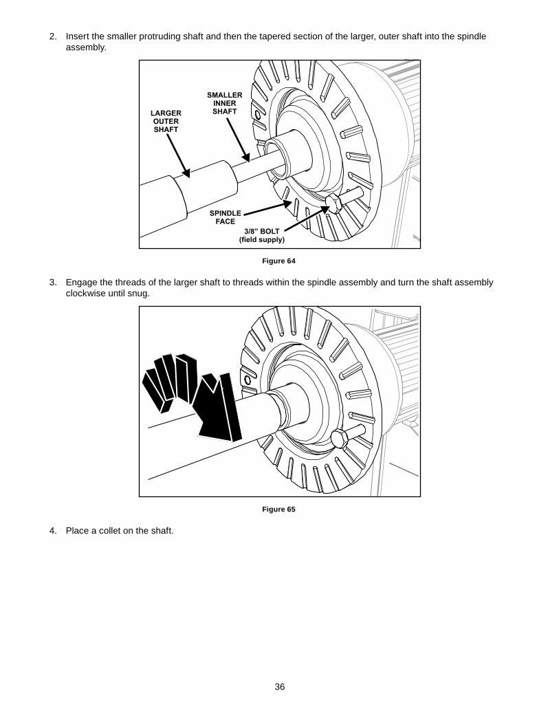
2. Insert the smaller protruding shaft and then the tapered section of the larger, outer shaft into the spindle assembly.
3/8” BOLT(field supply)
SPINDLEFACE
SMALLERINNERSHAFTLARGER
OUTERSHAFT
Figure 64
3. Engage the threads of the larger shaft to threads within the spindle assembly and turn the shaft assembly clockwise until snug.
Figure 65
4. Place a collet on the shaft.
37
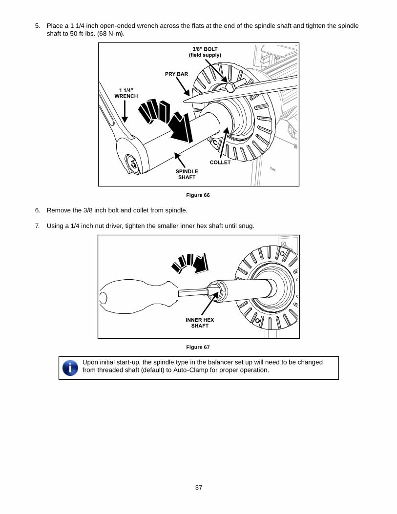
5. Place a 1 1/4 inch open-ended wrench across the flats at the end of the spindle shaft and tighten the spindle shaft to 50 ft-lbs. (68 N-m).
3/8” BOLT(field supply)
PRY BAR
COLLET
SPINDLESHAFT
1 1/4”WRENCH
Figure 66
6. Remove the 3/8 inch bolt and collet from spindle.
7. Using a 1/4 inch nut driver, tighten the smaller inner hex shaft until snug.
INNER HEXSHAFT
Figure 67
Upon initial start-up, the spindle type in the balancer set up will need to be changed from threaded shaft (default) to Auto-Clamp for proper operation.
38
INSTALL AdjUSTABLe LeG
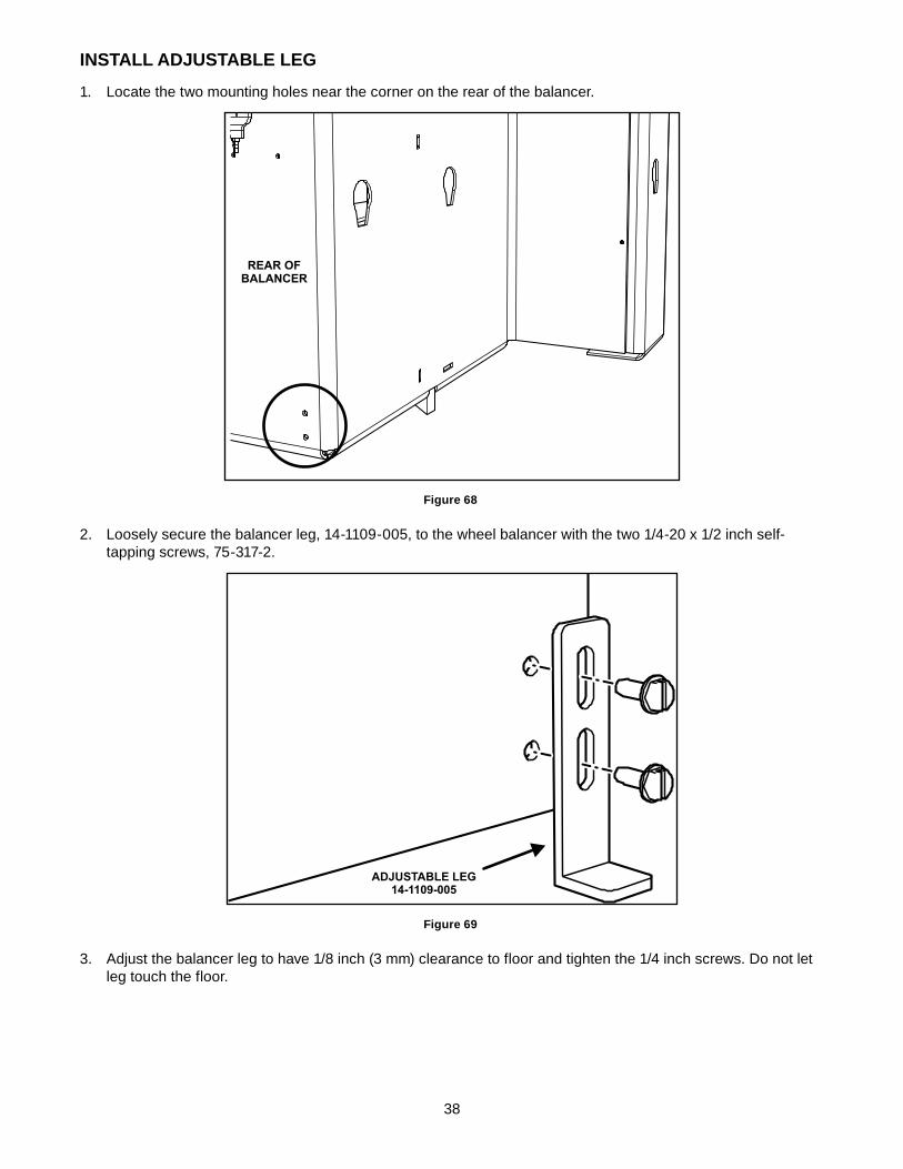
1. Locate the two mounting holes near the corner on the rear of the balancer.
REAR OFBALANCER
Figure 68
2. Loosely secure the balancer leg, 14-1109-005, to the wheel balancer with the two 1/4-20 x 1/2 inch self-tapping screws, 75-317-2.
ADJUSTABLE LEG14-1109-005
Figure 69
3. Adjust the balancer leg to have 1/8 inch (3 mm) clearance to floor and tighten the 1/4 inch screws. Do not let leg touch the floor.
39
BeLT BReAK-IN
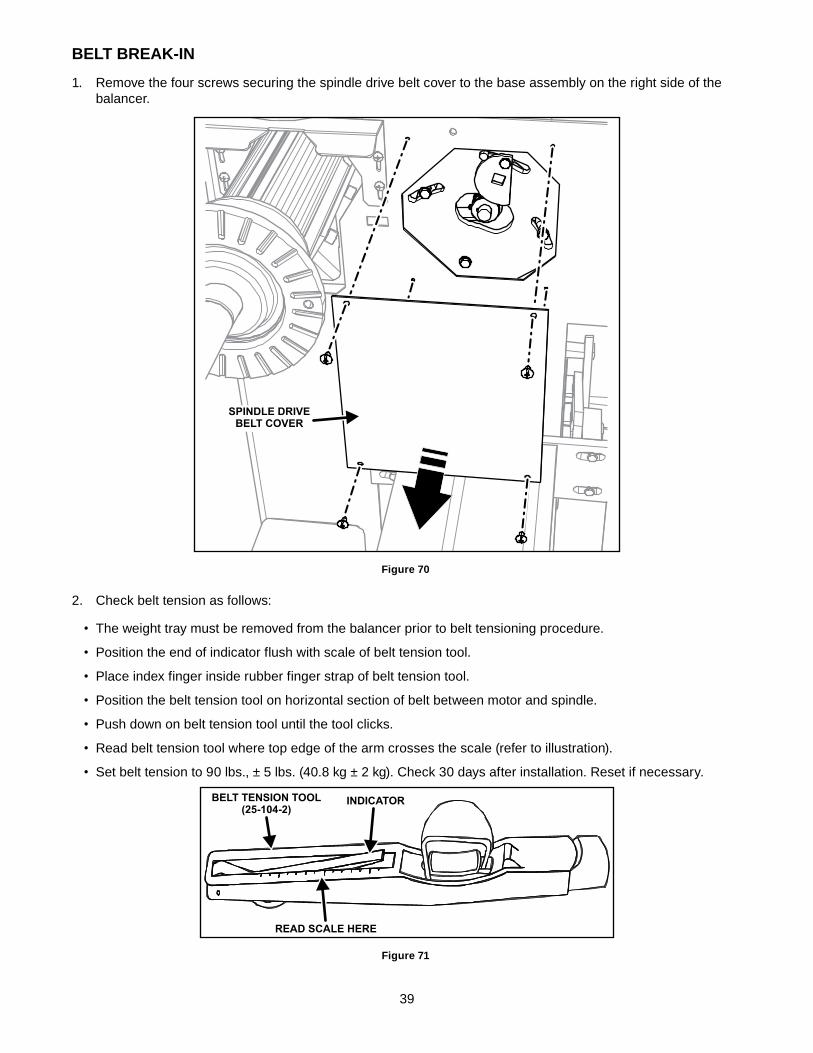
1. Remove the four screws securing the spindle drive belt cover to the base assembly on the right side of the balancer.
SPINDLE DRIVEBELT COVER
Figure 70
2. Check belt tension as follows:
• The weight tray must be removed from the balancer prior to belt tensioning procedure.
• Position the end of indicator flush with scale of belt tension tool.
• Place index finger inside rubber finger strap of belt tension tool.
• Position the belt tension tool on horizontal section of belt between motor and spindle.
• Push down on belt tension tool until the tool clicks.
• Read belt tension tool where top edge of the arm crosses the scale (refer to illustration).
• Set belt tension to 90 lbs., ± 5 lbs. (40.8 kg ± 2 kg). Check 30 days after installation. Reset if necessary.
BELT TENSION TOOL(25-104-2)
INDICATOR
READ SCALE HERE
Figure 71
40
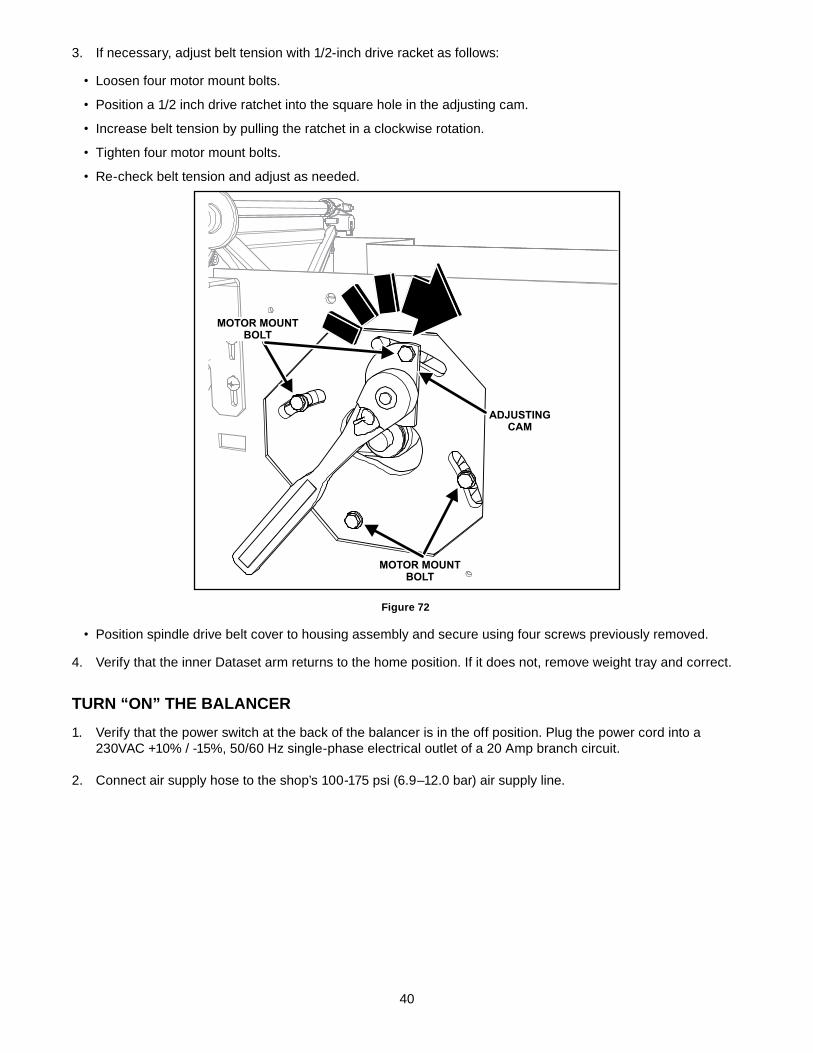
3. If necessary, adjust belt tension with 1/2-inch drive racket as follows:
• Loosen four motor mount bolts.
• Position a 1/2 inch drive ratchet into the square hole in the adjusting cam.
• Increase belt tension by pulling the ratchet in a clockwise rotation.
• Tighten four motor mount bolts.
• Re-check belt tension and adjust as needed.
ADJUSTINGCAM
MOTOR MOUNTBOLT
MOTOR MOUNTBOLT
Figure 72
• Position spindle drive belt cover to housing assembly and secure using four screws previously removed.
4. Verify that the inner Dataset arm returns to the home position. If it does not, remove weight tray and correct.
TURN “ON” The BALANCeR
1. Verify that the power switch at the back of the balancer is in the off position. Plug the power cord into a 230VAC +10% / -15%, 50/60 Hz single-phase electrical outlet of a 20 Amp branch circuit.
2. Connect air supply hose to the shop’s 100-175 psi (6.9–12.0 bar) air supply line.
41
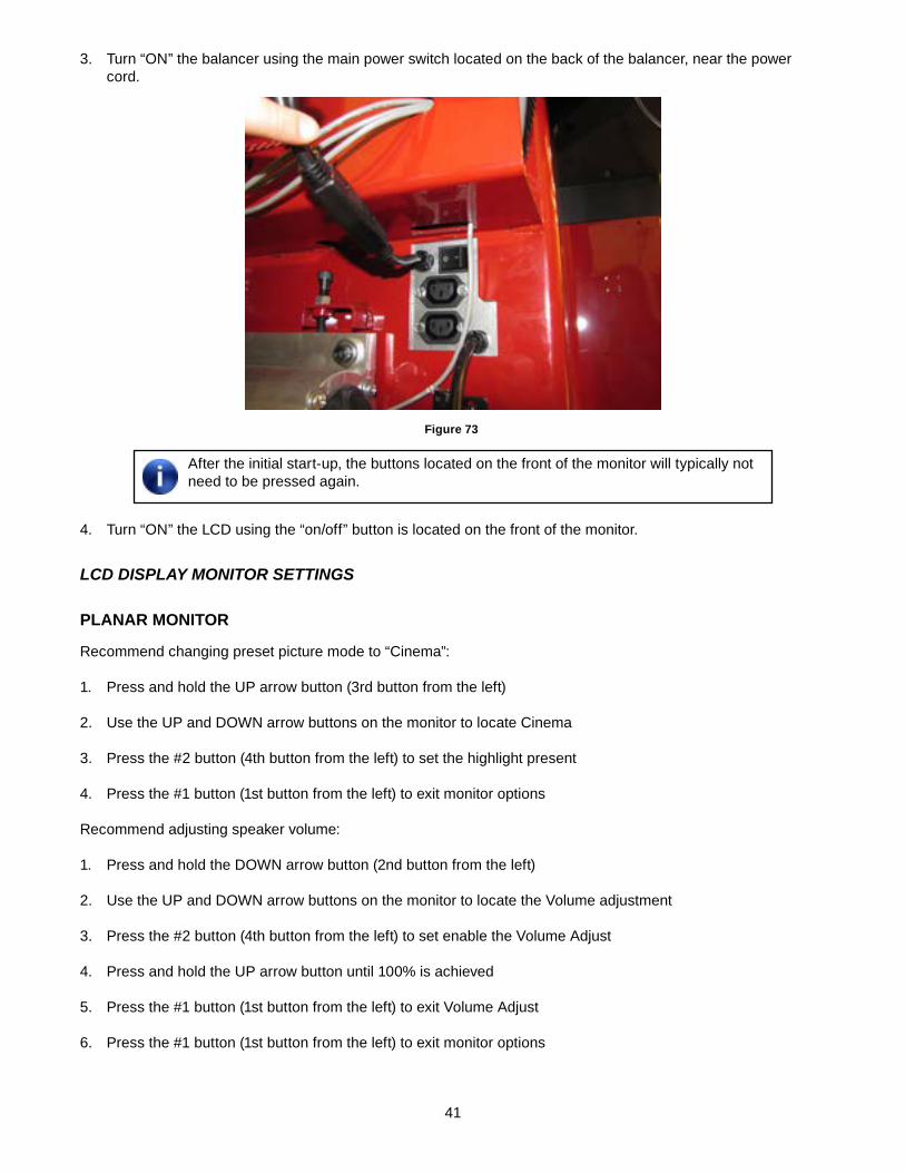
3. Turn “ON” the balancer using the main power switch located on the back of the balancer, near the power cord.
Figure 73
After the initial start-up, the buttons located on the front of the monitor will typically not need to be pressed again.
4. Turn “ON” the LCD using the “on/off” button is located on the front of the monitor.
lCD DiSplay monitor SettingS
PLANAR mONITOR
Recommend changing preset picture mode to “Cinema”:
1. Press and hold the UP arrow button (3rd button from the left)
2. Use the UP and DOWN arrow buttons on the monitor to locate Cinema
3. Press the #2 button (4th button from the left) to set the highlight present
4. Press the #1 button (1st button from the left) to exit monitor options
Recommend adjusting speaker volume:
1. Press and hold the DOWN arrow button (2nd button from the left)
2. Use the UP and DOWN arrow buttons on the monitor to locate the Volume adjustment
3. Press the #2 button (4th button from the left) to set enable the Volume Adjust
4. Press and hold the UP arrow button until 100% is achieved
5. Press the #1 button (1st button from the left) to exit Volume Adjust
6. Press the #1 button (1st button from the left) to exit monitor options
42
hP mONITOR
Recommend using “Auto Adjustment” for best possible picture:
Press the 4th button called “AUTO”
Highly recommend adjusting speaker volume:
1. Press MENU
2. Press RIGHT arrow button 4 times
3. Press MENU
4. Press RIGHT arrow button 3 times until Speaker Volume is highlighted
5. Press MENU
6. Press RIGHT arrow until volume level is at 100%
7. Press AUTO to exit volume adjustment
8. Press AUTO to exit monitor settings
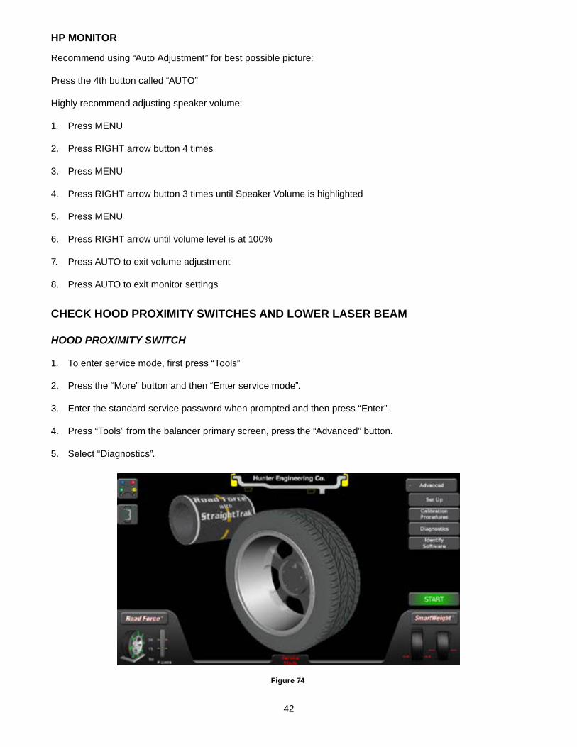
CheCK hOOd PROXImITY SwITCheS ANd LOweR LASeR BeAm
hooD proximity SwitCh
1. To enter service mode, first press “Tools”
2. Press the “More” button and then “Enter service mode”.
3. Enter the standard service password when prompted and then press “Enter”.
4. Press “Tools” from the balancer primary screen, press the “Advanced” button.
5. Select “Diagnostics”.
Figure 74
43
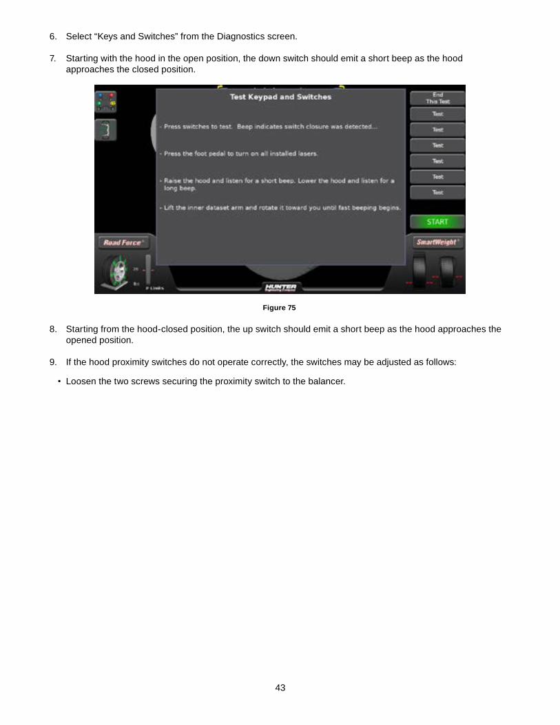
6. Select “Keys and Switches” from the Diagnostics screen.
7. Starting with the hood in the open position, the down switch should emit a short beep as the hood approaches the closed position.
Figure 75
8. Starting from the hood-closed position, the up switch should emit a short beep as the hood approaches the opened position.
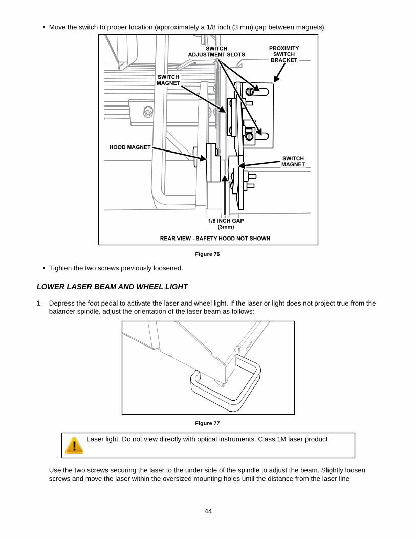
9. If the hood proximity switches do not operate correctly, the switches may be adjusted as follows:
• Loosen the two screws securing the proximity switch to the balancer.
44
• Move the switch to proper location (approximately a 1/8 inch (3 mm) gap between magnets).
SWITCHADJUSTMENT SLOTS
1/8 INCH GAP(3mm)
HOOD MAGNET
SWITCHMAGNET
SWITCHMAGNET
PROXIMITYSWITCH
BRACKET
REAR VIEW - SAFETY HOOD NOT SHOWN
Figure 76
• Tighten the two screws previously loosened.
lower laSer Beam anD wheel light
1. Depress the foot pedal to activate the laser and wheel light. If the laser or light does not project true from the balancer spindle, adjust the orientation of the laser beam as follows:
Figure 77
Laser light. Do not view directly with optical instruments. Class 1M laser product.
Use the two screws securing the laser to the under side of the spindle to adjust the beam. Slightly loosen screws and move the laser within the oversized mounting holes until the distance from the laser line
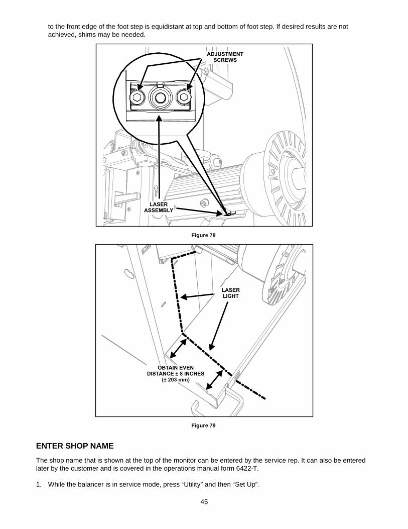
45
to the front edge of the foot step is equidistant at top and bottom of foot step. If desired results are not achieved, shims may be needed.
LASERASSEMBLY
ADJUSTMENTSCREWS
Figure 78
LASERLIGHT
OBTAIN EVENDISTANCE ± 8 INCHES
(± 203 mm)
Figure 79
eNTeR ShOP NAme
The shop name that is shown at the top of the monitor can be entered by the service rep. It can also be entered later by the customer and is covered in the operations manual form 6422-T.
1. While the balancer is in service mode, press “Utility” and then “Set Up”.
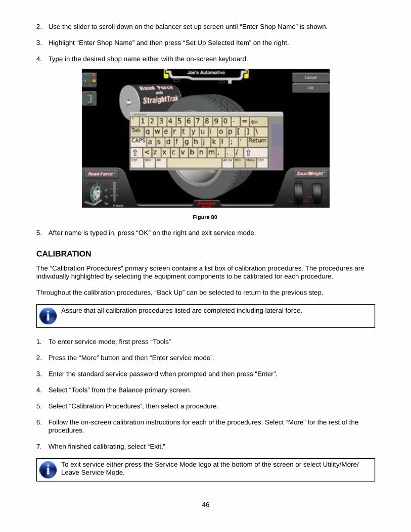
46
2. Use the slider to scroll down on the balancer set up screen until “Enter Shop Name” is shown.
3. Highlight “Enter Shop Name” and then press “Set Up Selected Item” on the right.
4. Type in the desired shop name either with the on-screen keyboard.
Figure 80
5. After name is typed in, press “OK” on the right and exit service mode.
CALIBRATION
The “Calibration Procedures” primary screen contains a list box of calibration procedures. The procedures are individually highlighted by selecting the equipment components to be calibrated for each procedure.
Throughout the calibration procedures, “Back Up” can be selected to return to the previous step.
Assure that all calibration procedures listed are completed including lateral force.
1. To enter service mode, first press “Tools”
2. Press the “More” button and then “Enter service mode”.
3. Enter the standard service password when prompted and then press “Enter”.
4. Select “Tools” from the Balance primary screen.
5. Select “Calibration Procedures”, then select a procedure.
6. Follow the on-screen calibration instructions for each of the procedures. Select “More” for the rest of the procedures.
7. When finished calibrating, select “Exit.”
To exit service either press the Service Mode logo at the bottom of the screen or select Utility/More/Leave Service Mode.
47
8. When the calibration is complete, thread the calibration weight into the threaded hole located near the base of the display support assembly.
9. Place the calibration weight storage decal near the upper right weld nut located on the back of the base assembly.
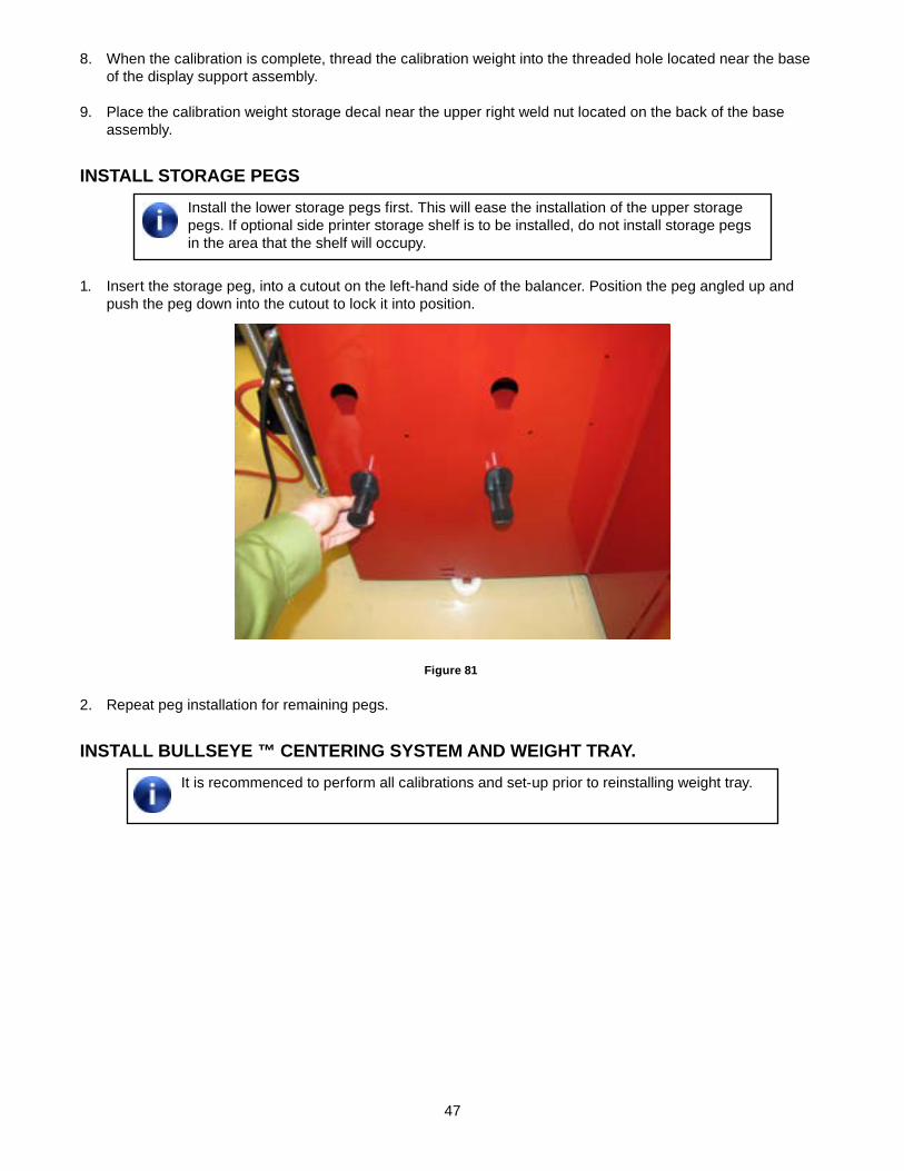
INSTALL STORAGe PeGSInstall the lower storage pegs first. This will ease the installation of the upper storage pegs. If optional side printer storage shelf is to be installed, do not install storage pegs in the area that the shelf will occupy.
1. Insert the storage peg, into a cutout on the left-hand side of the balancer. Position the peg angled up and push the peg down into the cutout to lock it into position.
Figure 81
2. Repeat peg installation for remaining pegs.
INSTALL BULLSeYe ™ CeNTeRING SYSTem ANd weIGhT TRAY.It is recommenced to perform all calibrations and set-up prior to reinstalling weight tray.
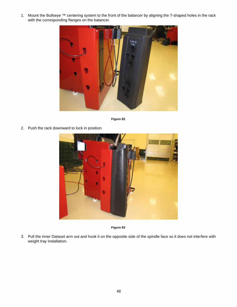
48
1. Mount the Bullseye ™ centering system to the front of the balancer by aligning the T-shaped holes in the rack with the corresponding flanges on the balancer.
Figure 82
2. Push the rack downward to lock in position.
Figure 83
3. Pull the inner Dataset arm out and hook it on the opposite side of the spindle face so it does not interfere with weight tray installation.
49
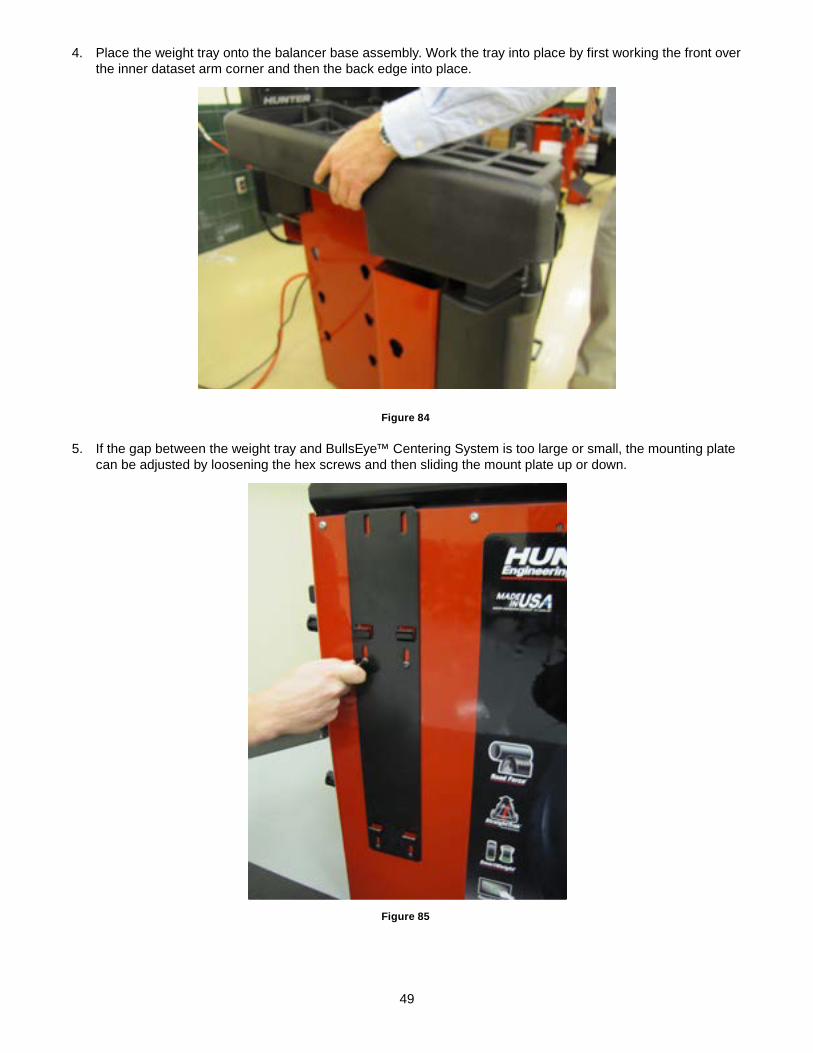
4. Place the weight tray onto the balancer base assembly. Work the tray into place by first working the front over the inner dataset arm corner and then the back edge into place.
Figure 84
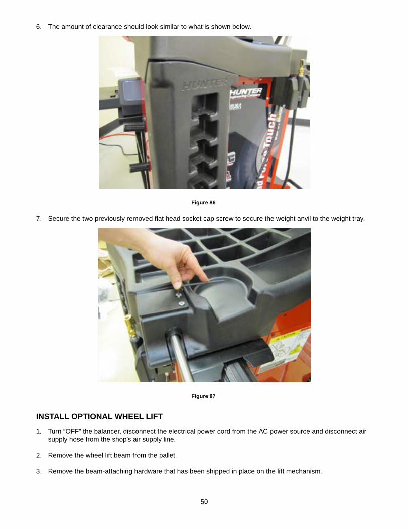
5. If the gap between the weight tray and BullsEye™ Centering System is too large or small, the mounting plate can be adjusted by loosening the hex screws and then sliding the mount plate up or down.
Figure 85
50
6. The amount of clearance should look similar to what is shown below.
Figure 86
7. Secure the two previously removed flat head socket cap screw to secure the weight anvil to the weight tray.
Figure 87
INSTALL OPTIONAL wheeL LIFT
1. Turn “OFF” the balancer, disconnect the electrical power cord from the AC power source and disconnect air supply hose from the shop’s air supply line.
2. Remove the wheel lift beam from the pallet.
3. Remove the beam-attaching hardware that has been shipped in place on the lift mechanism.
51
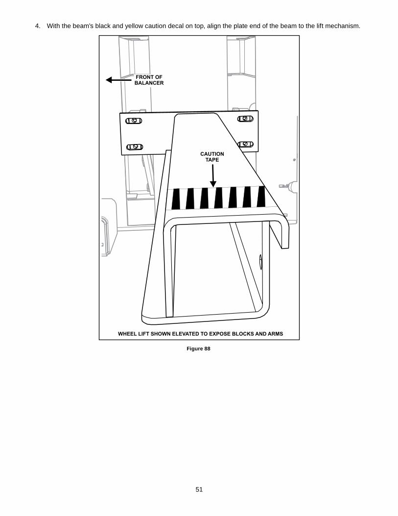
4. With the beam’s black and yellow caution decal on top, align the plate end of the beam to the lift mechanism.
FRONT OFBALANCER
WHEEL LIFT SHOWN ELEVATED TO EXPOSE BLOCKS AND ARMS
CAUTIONTAPE
Figure 88
52
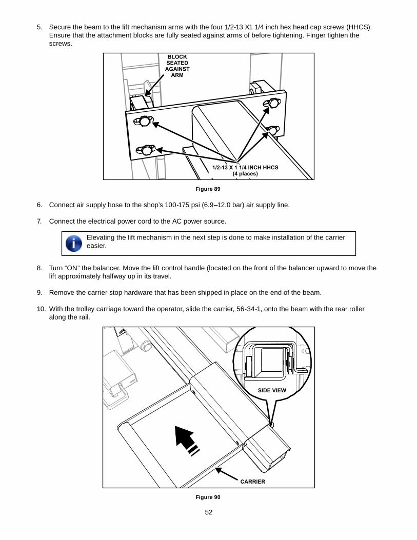
5. Secure the beam to the lift mechanism arms with the four 1/2-13 X1 1/4 inch hex head cap screws (HHCS). Ensure that the attachment blocks are fully seated against arms of before tightening. Finger tighten the screws.
BLOCKSEATEDAGAINST
ARM
1/2-13 X 1 1/4 INCH HHCS(4 places)
Figure 89
6. Connect air supply hose to the shop’s 100-175 psi (6.9–12.0 bar) air supply line.
7. Connect the electrical power cord to the AC power source.
Elevating the lift mechanism in the next step is done to make installation of the carrier easier.
8. Turn “ON” the balancer. Move the lift control handle (located on the front of the balancer upward to move the lift approximately halfway up in its travel.
9. Remove the carrier stop hardware that has been shipped in place on the end of the beam.
10. With the trolley carriage toward the operator, slide the carrier, 56-34-1, onto the beam with the rear roller along the rail.
CARRIER
SIDE VIEW
Figure 90
53
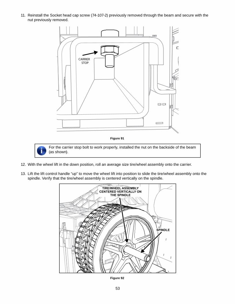
11. Reinstall the Socket head cap screw (74-107-2) previously removed through the beam and secure with the nut previously removed.
CARRIERSTOP
Figure 91
For the carrier stop bolt to work properly, installed the nut on the backside of the beam (as shown).
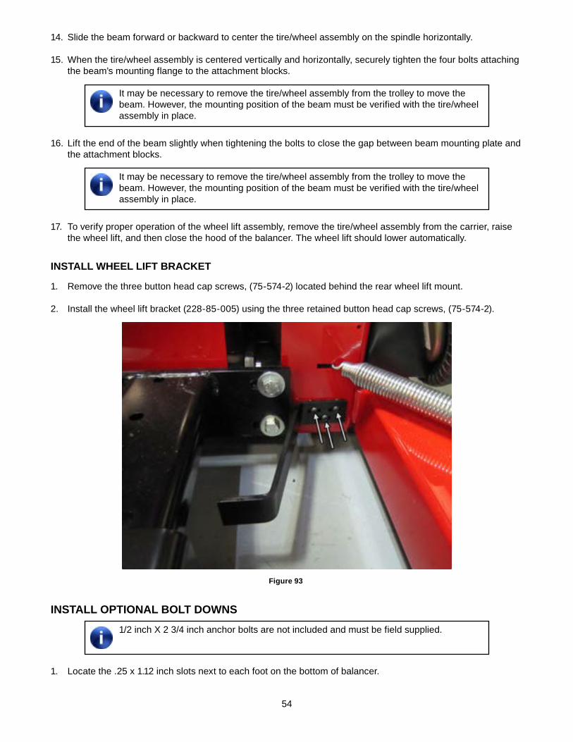
12. With the wheel lift in the down position, roll an average size tire/wheel assembly onto the carrier.
13. Lift the lift control handle “up” to move the wheel lift into position to slide the tire/wheel assembly onto the spindle. Verify that the tire/wheel assembly is centered vertically on the spindle.
SPINDLE
TIRE/WHEEL ASSEMBLYCENTERED VERTICALLY ON
THE SPINDLE
Figure 92
54
14. Slide the beam forward or backward to center the tire/wheel assembly on the spindle horizontally.
15. When the tire/wheel assembly is centered vertically and horizontally, securely tighten the four bolts attaching the beam’s mounting flange to the attachment blocks.
It may be necessary to remove the tire/wheel assembly from the trolley to move the beam. However, the mounting position of the beam must be verified with the tire/wheel assembly in place.
16. Lift the end of the beam slightly when tightening the bolts to close the gap between beam mounting plate and the attachment blocks.
It may be necessary to remove the tire/wheel assembly from the trolley to move the beam. However, the mounting position of the beam must be verified with the tire/wheel assembly in place.
17. To verify proper operation of the wheel lift assembly, remove the tire/wheel assembly from the carrier, raise the wheel lift, and then close the hood of the balancer. The wheel lift should lower automatically.
INSTALL wheeL LIFT BRACKeT
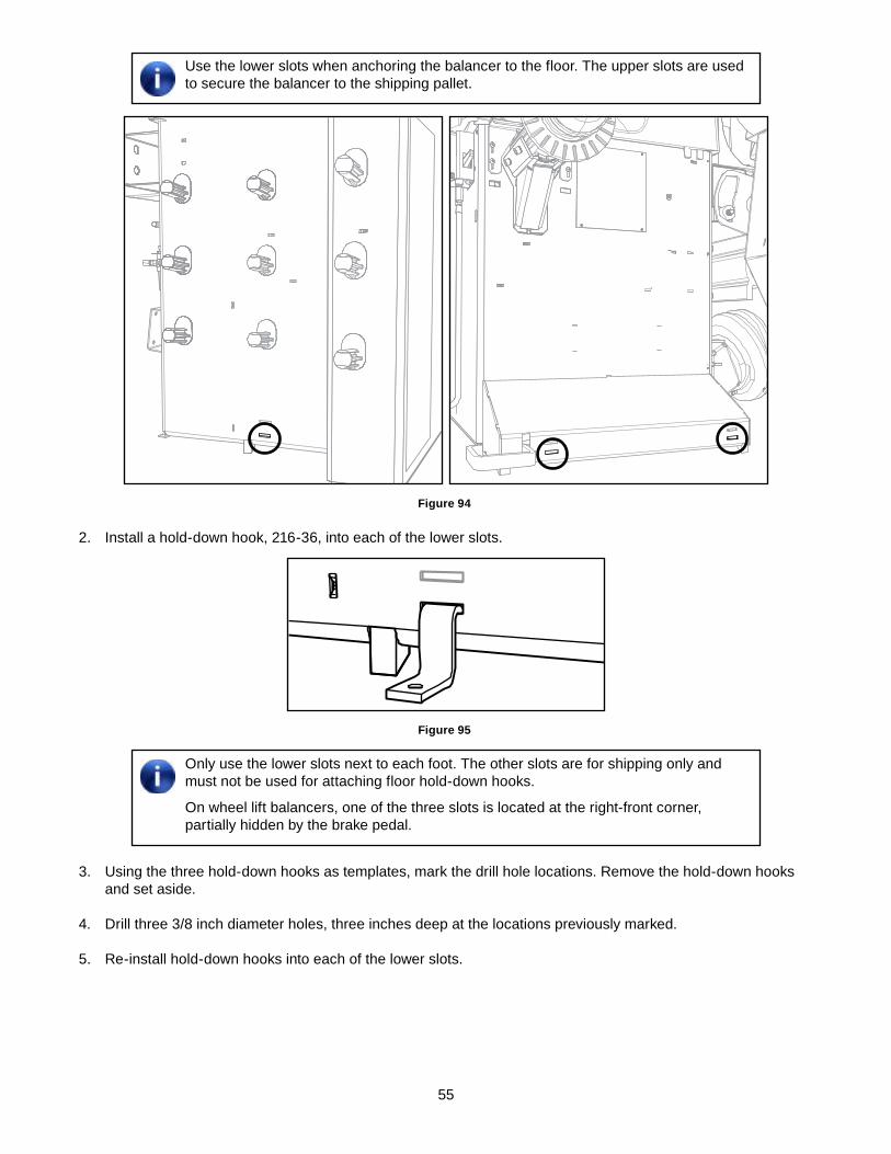
1. Remove the three button head cap screws, (75-574-2) located behind the rear wheel lift mount.
2. Install the wheel lift bracket (228-85-005) using the three retained button head cap screws, (75-574-2).
Figure 93
INSTALL OPTIONAL BOLT dOwNS1/2 inch X 2 3/4 inch anchor bolts are not included and must be field supplied.
1. Locate the .25 x 1.12 inch slots next to each foot on the bottom of balancer.
55
Use the lower slots when anchoring the balancer to the floor. The upper slots are used to secure the balancer to the shipping pallet.
Figure 94
2. Install a hold-down hook, 216-36, into each of the lower slots.
Figure 95
Only use the lower slots next to each foot. The other slots are for shipping only and must not be used for attaching floor hold-down hooks.
On wheel lift balancers, one of the three slots is located at the right-front corner, partially hidden by the brake pedal.
3. Using the three hold-down hooks as templates, mark the drill hole locations. Remove the hold-down hooks and set aside.
4. Drill three 3/8 inch diameter holes, three inches deep at the locations previously marked.
5. Re-install hold-down hooks into each of the lower slots.
56
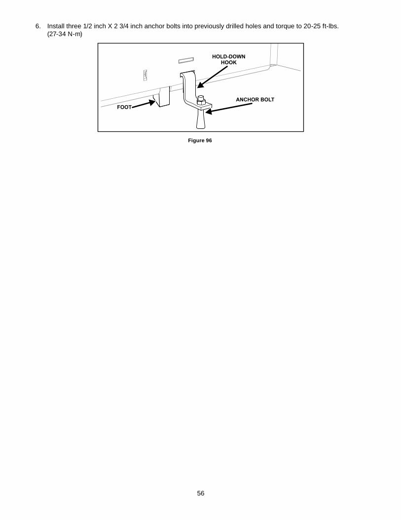
6. Install three 1/2 inch X 2 3/4 inch anchor bolts into previously drilled holes and torque to 20-25 ft-lbs. (27-34 N-m)
FOOT
HOLD-DOWNHOOK
ANCHOR BOLT
Figure 96