Embed Size (px)
Citation preview
© 2008, Snow Performance, Incorporated
INSTALLATION INSTRUCTIONSFOR PART #20020
WATER / METHANOL INJECTIONSYSTEMS

© 2008, Snow Performance, Inc
CONTENTSKit Contents.........................................................................3Introduction.........................................................................4Installation Mechanical....................................................4Installation Mechanical....................................................5Installation - Electrical......................................................10Variable Controller Installation ........................................10Calibrating RPM Switch....................................................11Variable Controller Tuning...............................................11Controller Operation Example .........................................12Testing the System ...........................................................13Tuning Quick Reference...................................................14Fluid Level Switch (optional) ...........................................16Solenoid Upgrade (optional) ............................................17Install Notes.......................................................................18Warranty Information ..19
CAUTIONYou must completely read though these instructions beforeinstalling and operating this product. Failure to due so canresult in damage to this product and the vehicle.
© 2008, Snow Performance, Inc
REGISTRATION CARDNAME____________________________________________________ADDRESS__________________________________________APT.___CITY_______________________________STATE__________ZIP____EMAIL____________________________________________________Return with proof of purchase (copy of sales receipt) within 90 daysof purchase date to:Snow Performance213 Aspen Garden Way - Bldg. #1Woodland Park, CO 80863This registration card MUST be returned to activate your LIFETIMEWARRANTY.
How did you learn about the Boost Cooler® product? Internet Television Advertising Magazine Article/Advertising Racing Event Friend or Relative Purchase Location
Why did you buy a Boost Cooler® system? Increased Horsepower Reliability Warranty
Other:_________________ Cooling Efficiency Detonation ControlWhich of the following publications do you read regularly?
5.0 Mustang Euro Car Muscle Mustang & Fast Fords Stock Car Racing Automobile Four Wheeler National Dragster Super Chevy Auto Week GRM Off-Road Super Ford Car and Driver Hot Rod Trailer Life Popular Hot Roding Car Craft Mopar Muscle Road & Track Truckin Chevy High Performance Motorhome Sport Compact Car Truck Trends Cycle world Motor Trend
Sport Truck Other: _________Which Internet forums do you visit regularly?
3si.org superhonda.com pirate4x4.comOther vwvortex.com ls1tech.com honda-acura.net mustangworld.com ford-trucks.com corvetteforum.com honda-tech.com corral.net fordtruckworld srtforums.com clubsi.com rx7club.com waterinjection.info s2ki.com clubrsx.com clubwrx.net other: ___________ dsmtalk.com nasioc.com wrxlinks.com none dsmtuners.com lancerregister.com maxima.org
WHERE/DATE PURCHASED________________________________________________
ADDRESS________________________________________________________________
MAKE/MODEL/YEAR OF VEHICLE___________________________________________
SNOW PERFORMANCE PART NO.___________________________________________

© 2008, Snow Performance, Inc
Contact Us:
PhoneOffice (719) 633-3811Fax (719) 633-3496Tech Support Line (Toll Free) (866) 365-2762
Webhttp://www.snowperformance.net
[email protected]@[email protected]
MailSnow Performance, Inc213 Aspen Garden WayBldg. #1Woodland Park, CO 80863
NotesThe contents of this document are subject to change without prior notice.No part of or this entire document may be reproduced in any formwithout prior written permission of Snow Performance, Inc under thecopyright except for private use.
The names, addresses and telephone numbers mentioned are current asof November 21, 2008. Note that this information is subject to change.Please refer to www.snowperformance.net for current information.
© 2008, Snow Performance, Inc
Kit Contents
Partso 1 150+ psig Pumpo 3 Qt Reservoiro 10 ft Red High Pressure
Tubingo 4 ft Black Wire Loomo Installation Instructions
Electrical Packeto 1 Green LEDo 2 Blue Butt Connectorso 1 Wire spliceo 1 Large Eyehooko 1 Small Eyehooko 1 Male Connectoro 3 Female Connectorso 1 Vacuum “T”o VC-A10 Controller With
Harnesso 10 Tie Wraps
Required ToolsElectric Drill w/ Drill BitsAdjustable WrenchUtility KnifeScrewdriver – Phillips5/16” Open End Wrench1/8” NPT Tap
Mechanical Packeto 1 Nozzle Holdero 2 3/8” NPT – 1/8” NPT
Reducer Bushingso 2 1/8” NPT – ¼” Tube
Elbow Fittingso 1 3/8” NPT – ¼” Tube
Straight Fittingo 7 #8x1&1/2” Screwso 7 #8 Washerso 1 #6x1/2” Screwo 1 Stickero 18 in 1/8” Silicone tubingo 1 E-6000 (GOOP)
Nozzleso 60ML/MN (Yellow)o 100ML/MN (Black)o 175ML/MN (Green)o 225ML/MN (Purple)o 375ML/MN (Red)o 625ML/MN (Blue)
Upgradeso Bulkheado 2.5 Gallon Reservoiro Solenoido Hose Adaptor or Bungo Level Switcho SafeInjection®o Nitrobooster®o Dual Nozzleo Carb Plate

© 2008, Snow Performance, Inc
Introduction- Please refer to system diagram during install. The optional LevelSwitch Upgrade (#40030) is shown.
Nozzle Identification Chart:
Nozzle Color Nozzle Size Nozzle Color Nozzle SizeYellow 60 ml/min Purple 225 ml/minBlack 100 ml/min Red 375 ml/minGreen 175 ml/min Blue 625 ml/min
Low Fluid LED
Red
Black
Black
Green
Red Red
White
Red
White
Manifold Vacuum Source
Pump
White
White
Injection Status LED
EngineAir Intake
Air Flow
Throttle Plate
+12 Volt Key On
Engine Ground
Wire Connection
To Ignition coil low voltageterminal, or Tach output
VC-A10
Yellow
© 2008, Snow Performance, Inc
LIMITATION OF LIABILITYREPAIR OR REPLACEMENT OF A DEFECTIVE PRODUCT ISTHE ORIGINAL RETAIL PURCHASER’S EXCLUSIVEREMEDY UNDER THIS WARRANTY.DAMAGE OR INJURY TO THE ORIGINAL RETAILPURCHASER, TO HIS OR HER VEHICLE, CARGO, ORPROPERTY, AND/OR TO ANY OTHER PERSON ORPROPERTY IS NOT COVERED BY THIS WARRANTY.THIS WARRANTY IS EXPRESSLY MADE IN LIEU OF ANYAND ALL OTHER EXPRESS WARRANTIES, WHETHERORAL OR WRITTEN.SNOW PERFORMANCE’S SOLE LIABILITY IS LIMITED TOTHE REMEDY SET FORTH ABOVE. IN NO EVENT WILLSNOW BE LIABLE FOR ANY DIRECT, INDIRECT,CONSEQUENTIAL, INCIDENTAL, SPECIAL, EXEMPLARY,OR PUNITIVE DAMAGES OR FOR ANY OTHER DAMAGESOF ANY KIND OR NATURE (INCLUDING, BUT NOTLIMITED TO, LOST PROFITS OR LOST SALES).SOME STATES DO NOT ALLOW THE EXCLUSION ORLIMITATION OF INCIDENTAL OR CONSEQUENTIALDAMAGES, SO THE ABOVE LIMITATIONS MAY NOTAPPLY TO YOU.
Non-Warranty Repair/Retest
Products returned due to damage or misuse and Products retestedwith no problem found are subject to repair/retest charges andproduct will be returned to customer at customer’s expense. Apurchase order or credit card number must be provided in order toobtain an RMA (Return Merchandise Authorization) number priorto returning Product.
© 2008, Snow Performance, Inc
This warranty does not cover problems caused by normal wear andtear including aesthetic oxidation of surfaces, accidents, unlawfulvehicle operation, or modifications or repairs to product notperformed or authorized by Snow. This includes any product thatis disassembled or taken apart for any reason.In addition, this warranty does not cover problems resulting fromconditions beyond Snow’s control including, but not limited to,theft, misuse, overloading, or failure to assemble, mount or use theproduct in accordance with Snow’s written instructions orguidelines included with the product or made available to theoriginal retail purchaser.In the event of failure, Snow will repair or replace the part atSnow's sole discretion. Failures resulting from misapplication ormisuse of the Product, failure to adhere to any specifications orinstructions, or failure resulting from neglect, abuse, accidents, oract of nature are not covered under this warranty.
Warranty service may be obtained by calling 866-365-2762,getting an RMA (Return Merchandise Authorization), deliveringthe part to Snow along with proof of purchase. Customer agrees toinsure the Product or assume the risk of loss or damage in transit,to prepay shipping charges to Snow, and to use the originalshipping container or equivalent. Shipping for Warrantyreplacement parts shipped outside the continental US will becharged to customer.
© 2008, Snow Performance, Inc
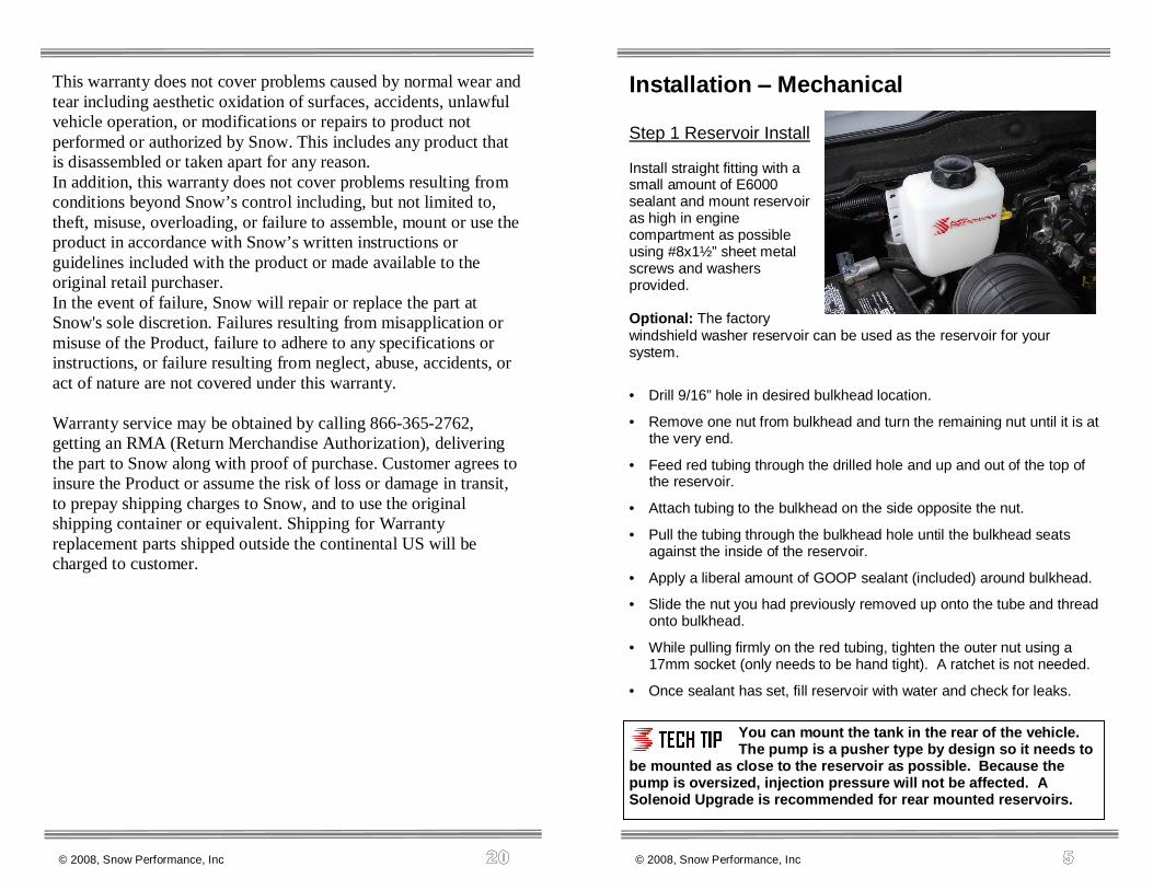
Installation Mechanical
Step 1 Reservoir Install
Install straight fitting with asmall amount of E6000sealant and mount reservoiras high in enginecompartment as possibleusing #8x1½” sheet metalscrews and washersprovided.
Optional: The factorywindshield washer reservoir can be used as the reservoir for yoursystem.
• Drill 9/16” hole in desired bulkhead location.
• Remove one nut from bulkhead and turn the remaining nut until it is atthe very end.
• Feed red tubing through the drilled hole and up and out of the top ofthe reservoir.
• Attach tubing to the bulkhead on the side opposite the nut.
• Pull the tubing through the bulkhead hole until the bulkhead seatsagainst the inside of the reservoir.
• Apply a liberal amount of GOOP sealant (included) around bulkhead.
• Slide the nut you had previously removed up onto the tube and threadonto bulkhead.
• While pulling firmly on the red tubing, tighten the outer nut using a17mm socket (only needs to be hand tight). A ratchet is not needed.
• Once sealant has set, fill reservoir with water and check for leaks.
You can mount the tank in the rear of the vehicle.The pump is a pusher type by design so it needs to
be mounted as close to the reservoir as possible. Because thepump is oversized, injection pressure will not be affected. ASolenoid Upgrade is recommended for rear mounted reservoirs.

© 2008, Snow Performance, Inc
Step 2 Pump Install
Install 3/8” NPT to 1/8” NPT plastic reducer bushing using GOOP sealanton threads. Tighten 2-3 turns past finger tight. Install 1/8” NPT elbowfitting into bushing using GOOP sealant on threads. Tighten 2-3 turnspast finger tight. Mount pump so the pump inlet is positioned at thelowest point of the reservoir or lower. Pump can be mounted horizontallyor vertically using (4) supplied #8x1½” screws and washers.
Measure the distance from the reservoir outlet to the pump inlet.
Cut the ¼” red tubing using utility knife. Make cuts are as square aspossible. Ensure there are no kinks in the tubing and insert tubing intoquick disconnects at pump and reservoir until fully seated.
NOTE: The new style pump is factory set at 150 psig. It can beturned up 1-2 full clockwise turns to increase pressure (180+ psigdepending on nozzle size).
Optional 2.5 Gal. Reservoir (#40020) Shown
© 2008, Snow Performance, Inc
Warranty
Snow Performance's commitment to providing the bestwater/methanol system is reflected in the components andconstruction of all Snow Performance Boost Cooler® kits.
A lifetime warranty for injection systems is available withexclusive use of Boost Juice injection fluid. The standard warrantyis 90 days from purchase and covers all Snow Performanceproducts and accessories purchased on or after October 30, 2008manufactured by Snow Performance, Inc. (Snow). This warrantyterminates when the original retail purchaser sells or otherwisetransfers the product to any other person.
Warranty Policy
Snow Performance, Inc. warrants that the Product shall conform toand perform in accordance with published technical specificationsand shall be free of defects in materials and workmanshipproviding:
1. You are the original purchaser and provide proof of purchase.
2. For lifetime warranty, the Warranty Card that came with system(not applicable to separate parts purchases) is returned to Snowwithin 90-days of purchase. If valid warranty card not on file withSnow, the standard 90 day warranty applies from date of purchase.
3. An RMA # has been attained and is displayed on packagecontaining returned part.
Subject to Snow’s inspection of the product, Snow will remedydefects in materials and/or workmanship by repairing or replacing,at Snow’s option, the defective product without charge for parts orlabor, subject to the limitations and exclusions described in thiswarranty.

© 2008, Snow Performance, Inc
Install Notes
Pump Setting ____________(psig)
Nozzle Size ____________(ml/min)
Boost / Vacuum setting _________
Misc:
DisclaimerDo not use this product until you have carefully read the following agreement.This sets forth the terms and conditions for the use of this product. The installation of thisproduct indicates that the BUYER has readand understands this agreement and accepts its terms and conditions.Performance products by their nature are designed to increase horsepower andperformance not engineered in the original vehicle and the increased stress could result indamage to related systems. This is a high performance product – use at your own risk.Snow Performance Inc., Its agents, employees or owners shall not be under any liabilitywhether in contract or otherwise whether or not resulting from our negligence or contents ofinformation supplied for any damage or loss resulting from such information.The BUYER is responsible to fully understand the capability and limitations of his/hervehicle according to manufacturer specificationsand agrees to hold the SELLER harmless from any damage resulting from failure to adhereto such specifications.The SELLER disclaims any warranty and expressly disclaims any liability for personalinjury or damages. The BUYER acknowledgesand agrees that the disclaimer of any liability for personal injury is a material term for thisagreement and the BUYER agrees toindemnify the SELLER and to hold the SELLER harmless from any claim related to theitem of the equipment purchased. Under nocircumstances will the SELLER be liable for any damages or expenses by reason of use orsale of any such equipment.The BUYER is responsible to obey all applicable federal, state, and local laws, statutes,and ordinances when operating his/hervehicle, and the BUYER agrees to hold SELLER harmless from any violation thereof.The SELLER assumes no liability regarding the improper installation or misapplication of itsproducts.It is the installer's responsibility to check for proper installation and if in doubt, contact themanufacturer.
© 2008, Snow Performance, Inc
Step 3 Nozzle Selection
Nozzle sizing is a function of horsepower, which approximates theengine airflow, and boost, which approximates intake charge heat.
Recommended starting points:
250 - 350 RWHP: 175ml/min nozzle. 350 - 475 RWHP: 375ml/min nozzle 475 - 600 RWHP 625ml/min nozzle
Seal the nozzle into the nozzle holder using GOOPsealant. Using a sealant that is not permanent will
allow for nozzle changes during tuning. Simply remove the nozzle,clean the threads, and reinstall using sealant.
Assemble desired nozzle into nozzle holder using methanol resistantsealant. The end of the nozzle with the fine mesh screen is to beinserted into the nozzle holder. Torque 1/2 turn past finger tight.
Correct Incorrect
NOTE: If nozzle is mounted lower then the reservoir, a Solenoid Upgrade(#40060) must be used to prevent draining.

© 2008, Snow Performance, Inc
Step 4 Nozzle Mounting
The nozzle assembly should be installed 90° to the direction of airflow.On round intake tubes, this is 360° around the tube meaning the nozzlecan be mounted in any direction. This will ensure maximum cooling asthe nozzle sprays in a cone pattern. Be sure that the nozzle is thehighest point in the system.
Drill and tap (11/32" pre-drill, 1/8”-27 NPT tap) air inlet tube as close aspossible to throttle body/throttle plate.
The nozzle is mounted into the intake using its external 1/8 NPT threads.Tighten the nozzle and nozzle holder assembly one half turn past handtight using methanol resistant sealant to seal the threads.
On carbureted applications the nozzle can be mounted before or afterthe throttle plate. A Carb Plate is available (#40050) for 4150 stylesquare bore carburetors.
You can mount the nozzle in a plastic or rubber air inlet tube using aNozzle Mounting Adapter (#40110). Weld-in aluminum (#40120) andsteel (#40130) bungs are available.
The recommended nozzle mounting point is beforethe throttle body/plate. If you mount the nozzle
after the throttle body/plate, a Solenoid Upgrade must be used toprevent siphoning at idle (#40060).
© 2008, Snow Performance, Inc
Pump
Injection Status LED
Red
Red
WhiteGreen from
Relay
Black
Black
Black
Air Flow
Throttle Plate
EngineAir Intake
IN OUT
Solenoid Upgrade (optional)
The optional Solenoid Upgrade (#40060) is required if the nozzle is to beinstalled after the intake throttle plate, or the fluid reservoir is mountedhigher then the nozzle.
Hand thread the two 1/8” NPT quick connect fittings into ports labeled INand OUT on the solenoid. Tighten an additional half turn.
Cut high pressure line at location solenoid is to be installed. Insert endsof cut line into quick connect fittings of solenoid. The port labeled IN isthe inlet and the port labeled OUT is the outlet. Firmly pull on line tocheck secure connection. If line pulls out, re-insert farther into fitting toengage locking clips. If high pressure line removal is required, firmlypress in plastic fitting ring to disengage locking clips while pulling hosefrom fitting.
Connect one of the BLACK wires from solenoid to the RED positivepump wire. Note that connecting the wire to any other power sourceother then the pump wire will result in improper operation of solenoid.Connect the second BLACK wire to a secure chassis ground location.

© 2008, Snow Performance, Inc
Fluid Level Switch (optional)
Instructions
• After mounting reservoir, mount red LED in dash next to thegreen “injection” LED is usually easiest.
• Wire LED per diagram with Red wire to a 12v key-on source, andthe White wire to one of the White wires of the level switch.
• Connect other White wire of the level switch to vehicle ground.
• With key-on source enabled, the red LED should be “on” with nofluid in the reservoir. Upon filling the reservoir, the red LEDshould be “off”.
The level switch is designed to indicate when thereis less than 1 of fluid in the reservoir.
Low Fluid LED
Red
White
White
© 2008, Snow Performance, Inc
Step 5 Nozzle Connection
Measure the distance from the pump outlet to the nozzle holder. Cut the¼” red tubing using utility knife. Make cuts are as square as possible.
Ensure there are no kinks in the tubing and insert tubing into quickdisconnects until fully seated. Gently pull on tubing to ensure a goodconnection.
Use tie wraps to help route tubing and to ensure it doesn't contactmoving or hot parts in the engine compartment. Have tubing connect toquick connect fittings at shallow angles. Having an immediate sharpbend may unseat the tubing from the internal o-ring and create a leak.
Continual insertion and removal from quick connect fittings will mar theend of the tubing. Over time the internal gripping teeth may lose theirhold of the tubing which may create a leak. If this occurs simply removethe tubing and make a fresh cut using a razor blade.

© 2008, Snow Performance, Inc
Installation - ElectricalVariable Controller Installation
The figure above shows the back view of the VC-A10 controller. Attachcontroller to secure location with easy access in engine bay orpassenger compartment. The VC series controllers are designed towithstand engine bay conditions, but should not be mounted directly tothe engine block. Connect vacuum hose from intake manifold to hosebarb on back of controller. Plug wire harness into back of controller.Note the terminal positions are numbered on the bottom side of wireharness connector. Your controller has an internal self resetting fusesuch that an external automotive type fuse is not required. In the case ofa fault, the internal fuse will attempt to reset after about 1 minute.
CAUTION: Disconnect the negative battery terminal whileconnecting wires to prevent electrical fire or damage to controller.
• Connect GREEN wire at position 4 to Pump Red power wire.
• Connect RED wire at position 3 to +12V key on source. Whenselecting a 12V key-on source, try to find a dedicated circuit with atleast a 15 AMP capability (25 AMP with 220psi pump).
• Connect YELLOW wire at position 2 to low voltage side (-) of primaryignition coil or engine tachometer signal wire.
• Connect BLACK wire at position 1 to a good ground location.
Always have a good electrical ground connection.Poor ground will result in erratic operation of
controller.
1 2 3 4
© 2008, Snow Performance, Inc
Maintenance Remove nozzle(s) and clean screen filters atleast once per year using carb cleaner.
The Boost Cooler® has been designed to operate with highconcentrations of methanol. Oil or other additives are not requiredfor system lubrication.
For best performance, cooling and system life it is recommend thatSnow Performance Boost Juice (#40008) be the exclusive fluidused in the system.

© 2008, Snow Performance, Inc
Tuning Quick ReferenceIncrease base timing in 2 degree increments until the first hint ofdetonation then back off 2 degrees (use 3rd gear pulls from2000 RPM).
The kit enables the use of increased timing which provides for over50% of the potential power increase (denser intake charge theremainder). All other factors being the same, if base timing is notincreased over the non-water/methanol injection settings, powerincrease will be less.
After tuning, ensure that reservoir has adequate fluid at all times. Itis recommended that reservoir always be at least 1/4 full.
The Boost Cooler® adds an alternate fuel source as well assignificantly cools combustion. With the Boost Cooler®, one doesnot need to cool combustion with overly rich air/fuel ratios. Tominimize combustion quench, you should start with an air to fuelratio of 12.0-12.5:1 with a conservative timing setting.
Injecting water/methanol lower than 3300 - 3500 RPM could result incombustion quench. If the engine bogs or loses power, then it iscoming on too early, the quantity is too much, or there is notenough methanol in the mixture (50/50 water/methanolrecommended).
If you have to increase the onset too high in the rpm range(detonation control is needed sooner), decrease pump pressureand/or go to a smaller nozzle.
In the black head of the pump, there is a 2mm Allen head screw thatwill regulate the pressure. On the 150 psig pump, for every full turncounter clockwise you will decrease the pump pressure by 18-20psig. On the 220 psig pump it will decrease the pump pressure 20-22psig for every turn counter clockwise.
When increasing the pump pressure, the allen screw will becometight. This is full pressure. BE CAREFUL NOT TO OVERTIGHTEN.If you go too far on the screw clockwise, then you can strip out theplastic threads.
© 2008, Snow Performance, Inc
Calibrating RPM Switch
The VC-A10 has an intern RPM switch that is programmable. Thisfeature sets the minimum RPM required to enable injection. The RPMswitch can be programmed at any time with the following steps:
• Start engine and wait 5 seconds for controller power up delay.
• Rev engine to desired injection RPM point and hold throttle positionconstant.
• Press and hold RED button on back of controller for 3-4 seconds.During this time controller will sample RPM signal and save readingto internal memory.
The factory programmed RPM point of the VC-A10 is beyond normalvehicle range and MUST be set during install per above procedurebefore injection will occur.
Variable Controller Tuning
The VC-A10 has a built in5 second power up delay.This feature helpsprevents injection duringengine starting.
The VC-A10 is designed to control injection based on engine load. Oncethe RPM switch is calibrated, the controller will activate injection basedon engine load whenever the engine RPM is greater then the calibratedRPM.
The following steps provide a guideline for initial dial settings. Additionalfine tuning of the dial positions might be required based on engineperformance and modification.
• Adjust the “Start” point first by turning dial clockwise to about onethird of the engines max vacuum. This sets the vacuum pressurerequired to activate the injection system.
• Next, adjust “Full” to the engines minimum vacuum.
• Note - over lapping the settings, where the Full dial is at highervacuum then Start, will result in max injection at the onset point.
• Adjust Full dial until a smooth power curve is felt with no misfiring.
12
Full 6
in.Hgvac
1 12 1
0
Start 6
VC-A10

© 2008, Snow Performance, Inc
Controller Operation Example
The above chart plots three different settings for the VC-A10water/methanol injection controller
For setting 1, GREEN, the chart shows the Start dial at 14 in. Hg and theFull dial at 6 inHg. At 14 inHg of manifold vacuum, the pump will operateat 10%. At 6 inHg of manifold vacuum, the pump will deliver 100% ofinjection pressure.
For manifold vacuum readings between the Start and Full settings, thecontroller will linearly adjust the pump pressure as shown on the graph.
0102030405060708090
100
14 12 10 8 6 4 2 0Vacuum in.Hg
Start
Pump
Output%
Full
© 2008, Snow Performance, Inc
Testing the System
Step 1 Test Pump and Mechanical System
Disconnect pump from controller. Using a 12 volt source, apply power tored wire of pump. Pump should activate, green LED should go on, andfluid level in tank should go down. It is recommended to also check thenozzle spray pattern while following this procedure. Also check for leaks.
If pump goes on and fluid level doesn't go down, there is an obstructionin the tube or nozzle.
Activation of pump for short periods (2 - 5 sec.) will not cause enginedamage.
Step 2 Test Controller
With the nozzle removed from intake, start vehicle and let it idle for 10seconds. Set the rpm switch with the motor at 1500. Increase engineRPM above 1500 rpm and remove the vacuum line from the controller.The controller is now detecting atmospheric pressure which is the samecondition as wide open throttle. The pump should activate, green LEDshould go on, and the fluid level in tank should go down. If system doesnot activate, check all wiring connections.