Embed Size (px)
Citation preview
Installation InstructionsFor Monsoon ExtraNegative Single Duty PumpMedium Pressure N1.3 bar High Pressure N2.4 barHigh Pressure N2.9 bar High Pressure N3.7 bar
INDEX ............................................... Page NoApplication . . . . . . . . . . . . . . . . . . . . . . . . 1
Storage . . . . . . . . . . . . . . . . . . . . . . . . . . 1
Typical Installation . . . . . . . . . . . . . . . . . . 2
Pre-Installation Assembly . . . . . . . . . . . . 2
Pump Location . . . . . . . . . . . . . . . . . . . . . 3
Pipework Connections . . . . . . . . . . . . . . . 5
Pump Connections . . . . . . . . . . . . . . . . . 7
INDEX ............................................... Page NoElectrical Installation . . . . . . . . . . . . . . . . 10
Commissioning . . . . . . . . . . . . . . . . . . . . 12
Maintenance . . . . . . . . . . . . . . . . . . . . . . 14
Technical Specification . . . . . . . . . . . . . . 16
Noise . . . . . . . . . . . . . . . . . . . . . . . . . . . . 17
Trouble Shooting Guide . . . . . . . . . . . . . . 17
Environment Protection . . . . . . . . . . . . . . 19
Please leave this instruction booklet with the pump as itcontains maintenance and safety information.
PRODUCT DESCRIPTIONElectric motor driven centrifugal pump complete with an automatic control system,
consisting of flow switch, pressure switch, pressure vessel and electronic control.
APPLICATIONThe Single Negative Monsoon Extra range is designed for pressure boosting
applications in vented stored, hot or cold, clean water systems, where under gravity, no
flow is available. Inlet pressures to the pump and ambient temperatures must not exceed
the values given in the technical specifications.
� This pump set must not be used for any other application without the written consent of Stuart Turner Limited and in particular, must not be connected directly to the mains water supply.
� This appliance is not intended for use by persons (including children) with reduced physical, sensory or mental capabilities, or lack of experience and knowledge, unless they have been given supervision or instruction concerning use of the appliance by a person responsiblefor their safety.Children should be supervised to ensure that they do not play with theappliance.
STORAGEIf this product is not to be installed immediately on receipt, ensure that it is stored in a
dry, frost and vibration free location in its original packaging.
- 2 -
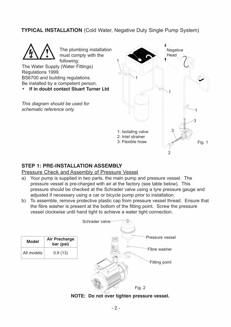
TYPICAL INSTALLATION (Cold Water, Negative Duty Single Pump System)
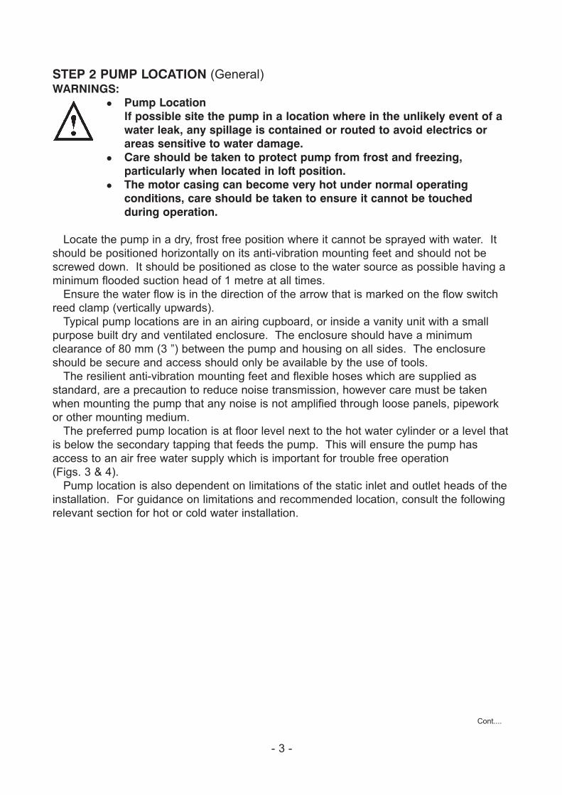
STEP 1: PRE-INSTALLATION ASSEMBLYPressure Check and Assembly of Pressure Vessela) Your pump is supplied in two parts, the main pump and pressure vessel. The
pressure vessel is pre-charged with air at the factory (see table below). This
pressure should be checked at the Schrader valve using a tyre pressure gauge and
adjusted if necessary using a car or bicycle pump prior to installation.
b) To assemble, remove protective plastic cap from pressure vessel thread. Ensure that
the fibre washer is present at the bottom of the fitting point. Screw the pressure
vessel clockwise until hand tight to achieve a water tight connection.
This diagram should be used for schematic reference only
1: Isolating valve
2: Inlet strainer
3: Flexible hose
1
3
2
Negative
Head
1
1
1
3
Fig. 1
The plumbing installation
must comply with the
following:
The Water Supply (Water Fittings)
Regulations 1999.
BS6700 and building regulations.
Be installed by a competent person.
• If in doubt contact Stuart Turner Ltd
Schrader valve
Pressure vessel
Fibre washer
Fig. 2
Fitting point
NOTE: Do not over tighten pressure vessel.
Model Air Prechargebar (psi)
All models 0.9 (13)
- 3 -
STEP 2 PUMP LOCATION (General)WARNINGS:
� Pump LocationIf possible site the pump in a location where in the unlikely event of a water leak, any spillage is contained or routed to avoid electrics or areas sensitive to water damage.
� Care should be taken to protect pump from frost and freezing, particularly when located in loft position.
� The motor casing can become very hot under normal operating conditions, care should be taken to ensure it cannot be touched during operation.
Locate the pump in a dry, frost free position where it cannot be sprayed with water. It
should be positioned horizontally on its anti-vibration mounting feet and should not be
screwed down. It should be positioned as close to the water source as possible having a
minimum flooded suction head of 1 metre at all times.
Ensure the water flow is in the direction of the arrow that is marked on the flow switch
reed clamp (vertically upwards).
Typical pump locations are in an airing cupboard, or inside a vanity unit with a small
purpose built dry and ventilated enclosure. The enclosure should have a minimum
clearance of 80 mm (3 ”) between the pump and housing on all sides. The enclosure
should be secure and access should only be available by the use of tools.
The resilient anti-vibration mounting feet and flexible hoses which are supplied as
standard, are a precaution to reduce noise transmission, however care must be taken
when mounting the pump that any noise is not amplified through loose panels, pipework
or other mounting medium.
The preferred pump location is at floor level next to the hot water cylinder or a level that
is below the secondary tapping that feeds the pump. This will ensure the pump has
access to an air free water supply which is important for trouble free operation
(Figs. 3 & 4).
Pump location is also dependent on limitations of the static inlet and outlet heads of the
installation. For guidance on limitations and recommended location, consult the following
relevant section for hot or cold water installation.
Cont....
- 4 -
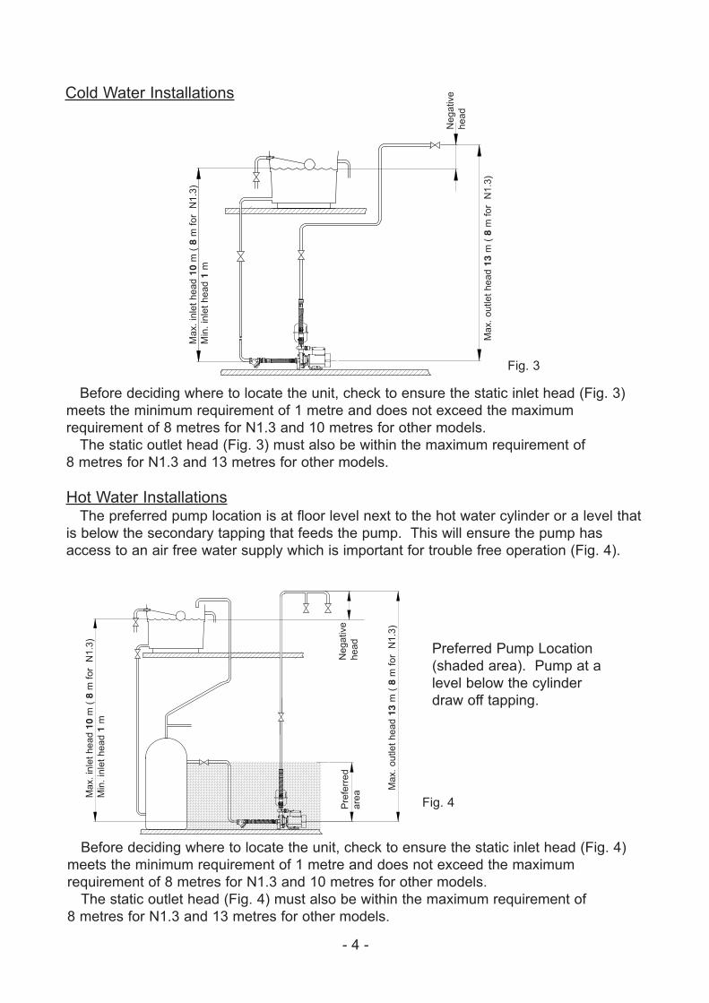
Cold Water Installations
Preferred Pump Location
(shaded area). Pump at a
level below the cylinder
draw off tapping.
Fig. 3
Ma
x.
inle
t h
ea
d 1
0m
( 8
m f
or
N1
.3)
Min
. in
let
he
ad
1m
Ne
ga
tive
he
ad
Fig. 4
Ma
x.
inle
t h
ea
d 1
0m
( 8
m f
or
N1
.3)
Min
. in
let
he
ad
1m
Ma
x.
ou
tle
t h
ea
d 1
3m
( 8
m f
or
N1
.3)
Ne
ga
tive
he
ad
Pre
ferr
ed
are
a
Before deciding where to locate the unit, check to ensure the static inlet head (Fig. 3)
meets the minimum requirement of 1 metre and does not exceed the maximum
requirement of 8 metres for N1.3 and 10 metres for other models.
The static outlet head (Fig. 3) must also be within the maximum requirement of
8 metres for N1.3 and 13 metres for other models.
Hot Water InstallationsThe preferred pump location is at floor level next to the hot water cylinder or a level that
is below the secondary tapping that feeds the pump. This will ensure the pump has
access to an air free water supply which is important for trouble free operation (Fig. 4).
Before deciding where to locate the unit, check to ensure the static inlet head (Fig. 4)
meets the minimum requirement of 1 metre and does not exceed the maximum
requirement of 8 metres for N1.3 and 10 metres for other models.
The static outlet head (Fig. 4) must also be within the maximum requirement of
8 metres for N1.3 and 13 metres for other models.
Ma
x.
ou
tle
t h
ea
d 1
3m
( 8
m f
or
N1
.3)
- 5 -
STEP 3 PIPEWORK CONNECTIONS (General)WARNINGS
� Ensure pipework to and from pump is independently supported to prevent forces being transferred to inlet and outlet branches of pump.
� Do not introduce solder flux to pumps or pump parts manufactured from plastic. All solder joints should be completed and flux residues removed prior to pump connection.
� Do not allow contact with oil or cellulose based paints, paint thinners or strippers, acid based descalents or aggressive cleaning agents.
� Always install isolating valves to both suction and delivery pipework.
� Do not install a non-return valve, or devices which contain non-return valves, in the suction (inlet) pipework to the pump. The pump must be free to vent to the supply tanks at all times.
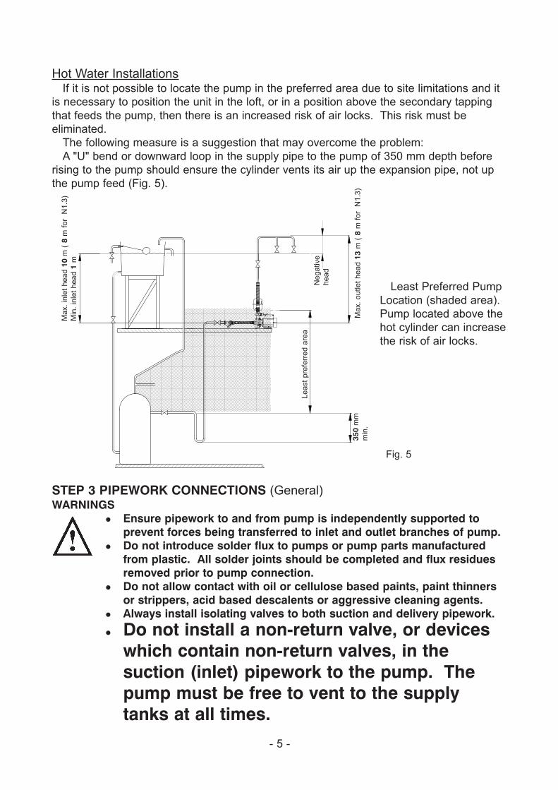
Hot Water InstallationsIf it is not possible to locate the pump in the preferred area due to site limitations and it
is necessary to position the unit in the loft, or in a position above the secondary tapping
that feeds the pump, then there is an increased risk of air locks. This risk must be
eliminated.
The following measure is a suggestion that may overcome the problem:
A "U" bend or downward loop in the supply pipe to the pump of 350 mm depth before
rising to the pump should ensure the cylinder vents its air up the expansion pipe, not up
the pump feed (Fig. 5).
Least Preferred Pump
Location (shaded area).
Pump located above the
hot cylinder can increase
the risk of air locks.
Fig. 5
Ma
x.
inle
t h
ea
d 1
0m
( 8
m f
or
N1
.3)
Min
. in
let
he
ad
1m
Ma
x.
ou
tle
t h
ea
d 1
3m
( 8
m f
or
N1
.3)
Ne
ga
tive
he
ad
Le
ast
pre
ferr
ed
are
a
350
mm
min
.
- 6 -
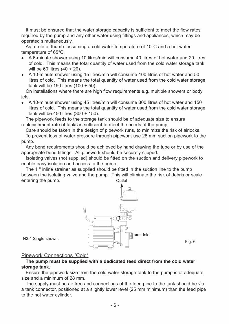
Outlet
Inlet
Fig. 6N2.4 Single shown.
It must be ensured that the water storage capacity is sufficient to meet the flow rates
required by the pump and any other water using fittings and appliances, which may be
operated simultaneously.
As a rule of thumb: assuming a cold water temperature of 10°C and a hot water
temperature of 65°C.
� A 6-minute shower using 10 litres/min will consume 40 litres of hot water and 20 litres
of cold. This means the total quantity of water used from the cold water storage tank
will be 60 litres (40 + 20).
� A 10-minute shower using 15 litres/min will consume 100 litres of hot water and 50
litres of cold. This means the total quantity of water used from the cold water storage
tank will be 150 litres (100 + 50).
On installations where there are high flow requirements e.g. multiple showers or body
jets.
� A 10-minute shower using 45 litres/min will consume 300 litres of hot water and 150
litres of cold. This means the total quantity of water used from the cold water storage
tank will be 450 litres (300 + 150).
The pipework feeds to the storage tank should be of adequate size to ensure
replenishment rate of tanks is sufficient to meet the needs of the pump.
Care should be taken in the design of pipework runs, to minimize the risk of airlocks.
To prevent loss of water pressure through pipework use 28 mm suction pipework to the
pump.
Any bend requirements should be achieved by hand drawing the tube or by use of the
appropriate bend fittings. All pipework should be securely clipped.
Isolating valves (not supplied) should be fitted on the suction and delivery pipework to
enable easy isolation and access to the pump.
The 1 " inline strainer as supplied should be fitted in the suction line to the pump
between the isolating valve and the pump. This will eliminate the risk of debris or scale
entering the pump.
Pipework Connections (Cold)The pump must be supplied with a dedicated feed direct from the cold water
storage tank.Ensure the pipework size from the cold water storage tank to the pump is of adequate
size and a minimum of 28 mm.
The supply must be air free and connections of the feed pipe to the tank should be via
a tank connector, positioned at a slightly lower level (25 mm minimum) than the feed pipe
to the hot water cylinder.
- 7 -
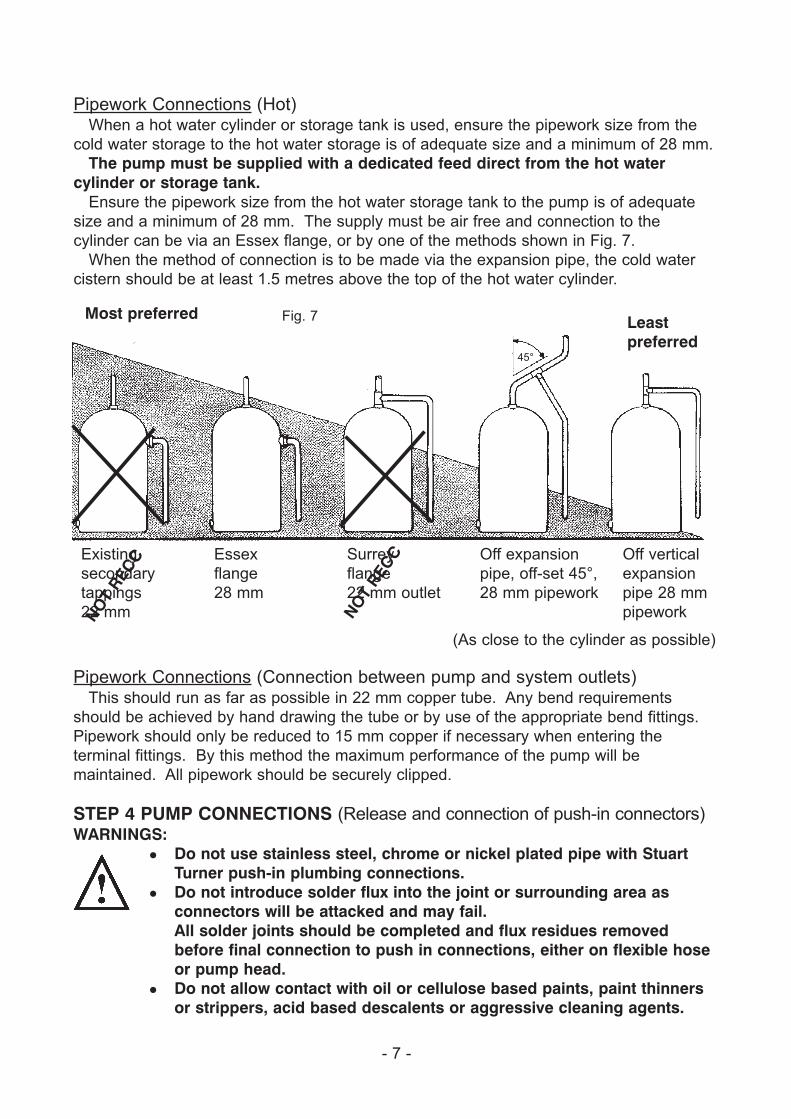
Pipework Connections (Hot)When a hot water cylinder or storage tank is used, ensure the pipework size from the
cold water storage to the hot water storage is of adequate size and a minimum of 28 mm.
The pump must be supplied with a dedicated feed direct from the hot watercylinder or storage tank.
Ensure the pipework size from the hot water storage tank to the pump is of adequate
size and a minimum of 28 mm. The supply must be air free and connection to the
cylinder can be via an Essex flange, or by one of the methods shown in Fig. 7.
When the method of connection is to be made via the expansion pipe, the cold water
cistern should be at least 1.5 metres above the top of the hot water cylinder.
(As close to the cylinder as possible)
Existing
secondary
tappings
22 mm
Essex
flange
28 mm
Surrey
flange
22 mm outlet
Off expansion
pipe, off-set 45°,
28 mm pipework
Off vertical
expansion
pipe 28 mm
pipework
Most preferred Fig. 7 Leastpreferred
NOT
REC
C
NOT
REC
C
45°
Pipework Connections (Connection between pump and system outlets)This should run as far as possible in 22 mm copper tube. Any bend requirements
should be achieved by hand drawing the tube or by use of the appropriate bend fittings.
Pipework should only be reduced to 15 mm copper if necessary when entering the
terminal fittings. By this method the maximum performance of the pump will be
maintained. All pipework should be securely clipped.
STEP 4 PUMP CONNECTIONS (Release and connection of push-in connectors)WARNINGS:
� Do not use stainless steel, chrome or nickel plated pipe with Stuart Turner push-in plumbing connections.
� Do not introduce solder flux into the joint or surrounding area as connectors will be attacked and may fail.All solder joints should be completed and flux residues removed before final connection to push in connections, either on flexible hose or pump head.
� Do not allow contact with oil or cellulose based paints, paint thinners or strippers, acid based descalents or aggressive cleaning agents.
- 8 -
DisconnectionTo break the joint, push the pipe into fitting, hold collet down and gently remove pipe by
pulling out of collet. If the system has been filled with water, care should be taken to
isolate the pump and towels used to absorb spilled water.
Connection1. Stuart Turner recommend only the use of their 22 mm flexible hoses.
The hose and pump are fitted with plastic push-in connectors, which must only be
connected with the following:
a) 22 mm diameter copper pipe to BS EN 1057 - R250 (half hard) - Table 3.
b) 22 mm plastic pipe to BS 7291 part 1 and part 2 (Table 1), or part 3 (Table 1) plus
internal support sleeve*.
* The internal bore of the plastic pipe must be supported against collapse with the
pipe manufacturers recommended support sleeve (pipe insert).
c) Appropriate plumbing fittings from the John Guest 'speedfit' push-in plumbing
fitting range.
Other manufacturers fittings are not necessarily compatible and may not provide a
water tight connection.
Ensure the pipe is free from all score marks and deformities in the area of the
insertion depth (Fig. 8) and cut the pipe square removing all burrs and sharp
edges to prevent damage to the sealing 'O'-ring.
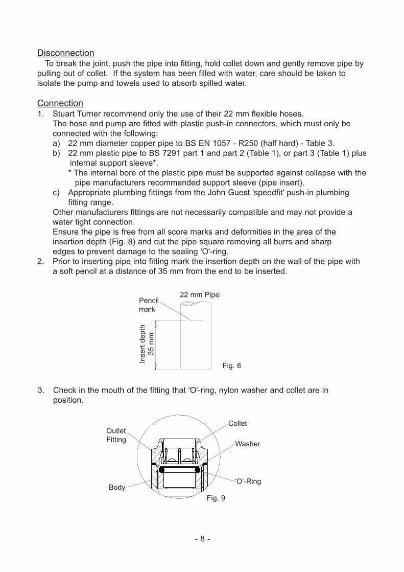
2. Prior to inserting pipe into fitting mark the insertion depth on the wall of the pipe with
a soft pencil at a distance of 35 mm from the end to be inserted.
3. Check in the mouth of the fitting that 'O'-ring, nylon washer and collet are in
position.
Pencil
mark
22 mm Pipe
Inse
rt d
ep
th
35
mm
Fig. 8
Collet
Washer
‘O’-Ring
Fig. 9
Outlet
Fitting
Body
- 9 -
4. Push pipe firmly into fitting, until pencil mark is level with the top of the collet and the
pipe stop resistance is felt. Pull on the pipe to check it is secure and correctly fitted.
If you have any concern either about using push-in fittings or should the joint leak on
final test isolate the water supplies and contact Stuart Turner Service Dept. on 01491
572655.
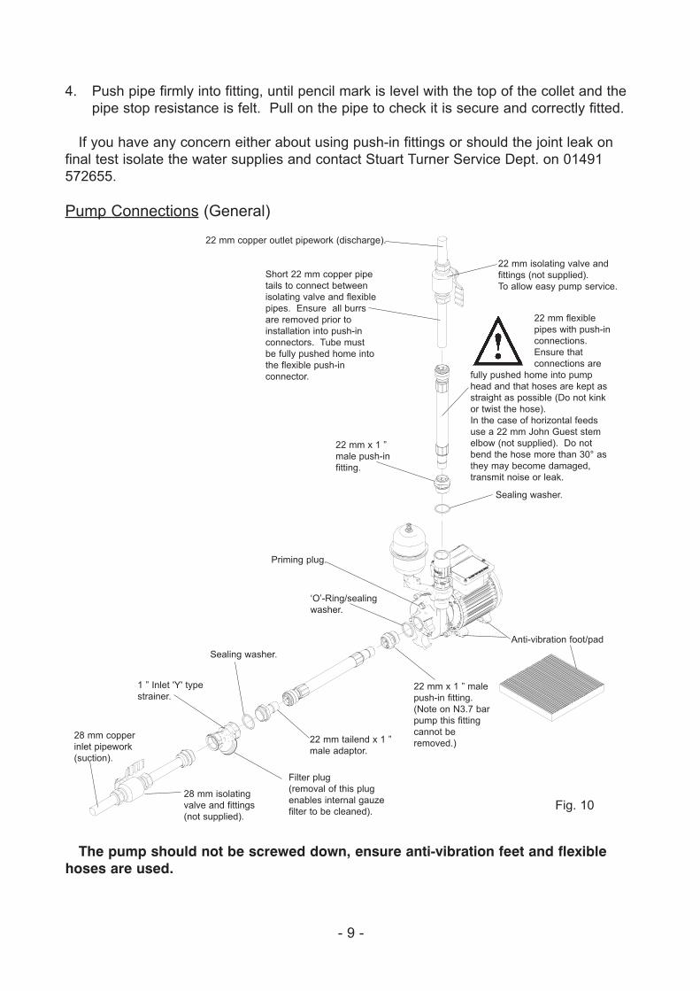
Pump Connections (General)
The pump should not be screwed down, ensure anti-vibration feet and flexiblehoses are used.
Fig. 10
22 mm copper outlet pipework (discharge).
22 mm isolating valve and
fittings (not supplied).
To allow easy pump service.
22 mm flexible
pipes with push-in
connections.
Ensure that
connections are
fully pushed home into pump
head and that hoses are kept as
straight as possible (Do not kink
or twist the hose).
In the case of horizontal feeds
use a 22 mm John Guest stem
elbow (not supplied). Do not
bend the hose more than 30° as
they may become damaged,
transmit noise or leak.
Sealing washer.
Anti-vibration foot/pad
22 mm x 1 ” male
push-in fitting.
(Note on N3.7 bar
pump this fitting
cannot be
removed.)22 mm tailend x 1 ”
male adaptor.
1 ” Inlet 'Y' type
strainer.
28 mm isolating
valve and fittings
(not supplied).
28 mm copper
inlet pipework
(suction).
Filter plug
(removal of this plug
enables internal gauze
filter to be cleaned).
Sealing washer.
‘O’-Ring/sealing
washer.
Priming plug.
22 mm x 1 ”
male push-in
fitting.
Short 22 mm copper pipe
tails to connect between
isolating valve and flexible
pipes. Ensure all burrs
are removed prior to
installation into push-in
connectors. Tube must
be fully pushed home into
the flexible push-in
connector.
- 10 -
STEP 5 ELECTRICAL INSTALLATIONWARNINGS:
� The electrical installation must be carried out in accordance with the current national electrical regulations and installed by a competent person.
� In the interests of electrical safety a 30 mA residual current device (R.C.D.) should be installed in the supply circuit. This may be part of a consumer unit or a separate unit.
� Before starting work on the electrical supply ensure power supply is isolated.
� This appliance must be earthed.� The motor and wiring must not be exposed to water. � Do not allow the supply cord to contact hot surfaces, including the
motor shell, pump body or pipework. The cord should be safely routed and secured by cable clips.
The motor fitted to this pump is suitable for a 230/1/50Hz supply. It is thermally
protected by an integral auto resetting thermotrip for your safety and rated for the duty
listed in the technical specification section.
Electrical ConnectionThe motor is provided with a factory fitted supply cord. This must be permanently
connected to the fixed wiring of the mains supply. Means for disconnection must be
incorporated in the fixed wiring in accordance with the wiring rules.
A suitable method of connection would be via a double pole switched, fused connection
unit complying with BS 1363-4, protected with a fuse (see fuse section).
The connection unit should be mounted in an easily accessible position and should be
labelled if confusion is possible, to allow easy identification of the pump isolating switch.
EarthingThis appliance must be earthed via the supply cord, which must be correctly connected
to the earth point located in the terminal box.
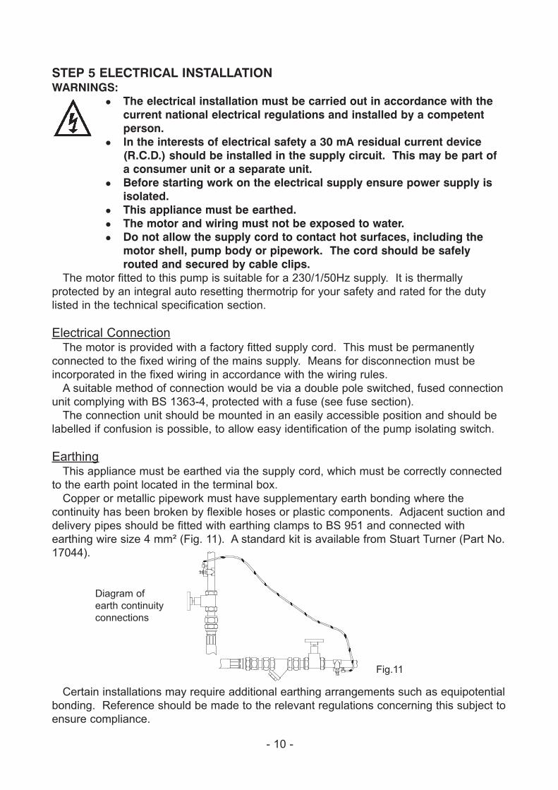
Copper or metallic pipework must have supplementary earth bonding where the
continuity has been broken by flexible hoses or plastic components. Adjacent suction and
delivery pipes should be fitted with earthing clamps to BS 951 and connected with
earthing wire size 4 mm² (Fig. 11). A standard kit is available from Stuart Turner (Part No.
17044).
Certain installations may require additional earthing arrangements such as equipotential
bonding. Reference should be made to the relevant regulations concerning this subject to
ensure compliance.
Diagram of
earth continuity
connections
Fig.11
MAIN WINDING
THERMOTRIP CAPACITOR
START WINDING
LINK
WIR
E
BROW
N
BLAC
K
GREEN/YELLOW
BLUEBROWN L
MA
N
N
S2 S3 S3 S2
LE
N
FLOWSWITCHREED (S3)
S1S1
PRESSURESWITCH (S1)
230 VAC/1PH/50HzSUPPLY
BLUE
FusesThe following fuse size should be used with the appropriate pump:
- 11 -
Wiring of connection unit
WARNING: This appliance must be earthed.
The wires in the mains lead are coloured in accordance with the following code:
Green and Yellow: Earth Blue: Neutral Brown: Live
As the colours of the wires in the mains lead of this appliance may not correspond with
the coloured markings identifying the terminals in your connection unit proceed as follows:
The wire which is coloured green and yellow must be connected to the terminal in the
connection unit which is marked with the letter E or by the earth symbol: or coloured
green or green and yellow.
The wire which is coloured blue must be connected to the terminal which is marked with
the letter N or coloured black.
The wire which is coloured brown must be connected to the terminal which is marked
with the letter L or coloured red.
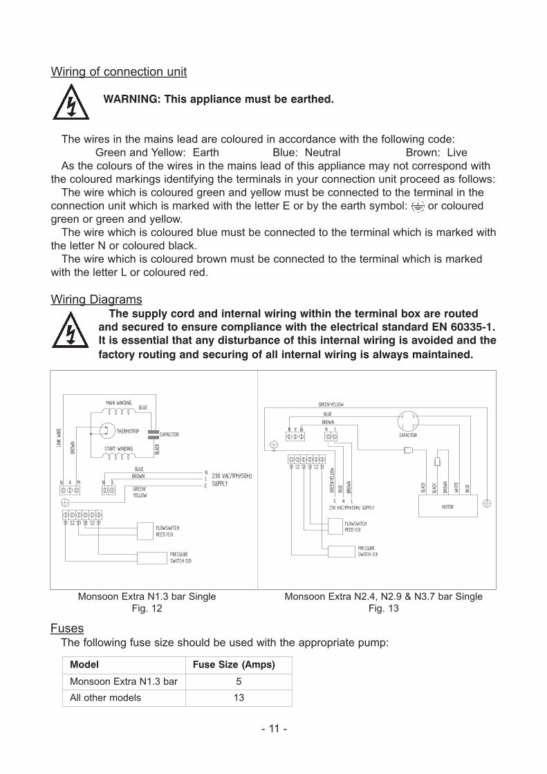
Wiring DiagramsThe supply cord and internal wiring within the terminal box are routed
and secured to ensure compliance with the electrical standard EN 60335-1.It is essential that any disturbance of this internal wiring is avoided and thefactory routing and securing of all internal wiring is always maintained.
Monsoon Extra N1.3 bar Single
Fig. 12
Monsoon Extra N2.4, N2.9 & N3.7 bar Single
Fig. 13
Model Fuse Size (Amps)
Monsoon Extra N1.3 bar 5
All other models 13
N A M
E
GREE
N/YE
LLOW
BROWN
BLUE
GREEN/YELLOW
CAPACITOR
MOTOR
BLAC
K
BLAC
K
BROW
N
WHI
TE
BLUE
N
S2 S3 S3 S2
L
FLOWSWITCHREED (S3)
S1S1
PRESSURESWITCH (S1)
LN
BROW
N
BLUE
230 VAC/1PH/50Hz SUPPLY
- 12 -
Supply Cord ReplacementIf the supply cord needs to be replaced, cord selection should be chosen in accordance
with the current involved, surrounding conditions and recommended fuse size. For
information on cable fitting and connection, consult the wiring diagram and cable gland
fitting instructions.
Intermediate Connecting Cord Replacement (Monsoon N2.4, N2.9 & N3.7 models only)
These pumps incorporate an additional cord which connects the main terminal box to
the motor terminal box. If this cord is damaged, it must be replaced with a special cord
assembly available from Stuart Turner or one of their approved repairers.
On disassembly note the cord retention and routing system. Reassemble to the same
pattern.
For information on cable connection consult the wiring diagram.
Supply Cord ExtensionThe pumps are fitted with a supply cord to the following specification:-
Monsoon Extra N1.3 bar:- . . . . . . . . . . . . . HO5VV-F3 G 0.75 mm² - 6 Amp rated cable.
Monsoon Extra N2.4, N2.9 & N3.7 bar:- . . . HO7RN-F3 G 1.0 mm² - 10 Amp rated cable.
If the supply cord is to be extended, a cord of the same specification should be used.
Any connections or junction boxes used should be specifically suited for the application
and installed in accordance with the manufacturers instructions.
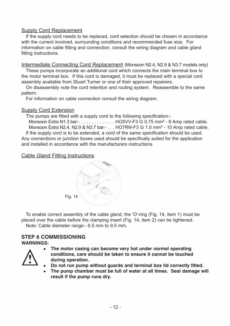
Cable Gland Fitting Instructions
To enable correct assembly of the cable gland, the 'O'-ring (Fig. 14, item 1) must be
placed over the cable before the clamping insert (Fig. 14, item 2) can be tightened.
Note: Cable diameter range:- 6.5 mm to 9.5 mm.
STEP 6 COMMISSIONINGWARNINGS:
� The motor casing can become very hot under normal operating conditions, care should be taken to ensure it cannot be touched during operation.
� Do not run pump without guards and terminal box lid correctly fitted.� The pump chamber must be full of water at all times. Seal damage will
result if the pump runs dry.
Fig. 14
PUMPS
PUMPS
1. System Flushing
This pump incorporates push-in connectors and plastic components that
must not come into contact with solder flux, acid-based descalents or
aggressive cleaning agents. The pipework system should be flushed out
prior to the pump being connected to ensure any contaminants/chemical
residues and foreign bodies are removed from elsewhere in the system.
2. Water Supply
Always ensure that water storage capacity is adequate to meet the
demand. Ensure the pump chamber is full of water before starting the
pump. Failure to do this could result in seal damage. To ensure dry
running does not occur the pump must be primed as described in priming
section. Do not run pump dry.
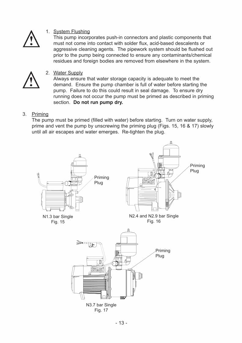
3. Priming
The pump must be primed (filled with water) before starting. Turn on water supply,
prime and vent the pump by unscrewing the priming plug (Figs. 15, 16 & 17) slowly
until all air escapes and water emerges. Re-tighten the plug.
- 13 -
N1.3 bar Single
Fig. 15
N2.4 and N2.9 bar Single
Fig. 16
N3.7 bar Single
Fig. 17
Priming
Plug
Priming
Plug
Priming
Plug
- 14 -
4. Starting The Pump
a) Ensure all outlets are closed, turn power supply ‘on’ - pump will start, pressurise
the system then stop.
b) Open and close all outlets in turn associated with the pump, (including w/c
systems) allowing water to flow from each outlet until all air is purged. As each
outlet is opened and closed, the pump will start and stop respectively.
Note: After closing the outlet there will be a small delay time before the pump
stops, which is normal.
Any tap or control valve within the system when opened and closed will now turn
the pump on/off. Providing this is the case the system is now operating correctly.
c) Carefully check pump and pipework for leaks whilst pump running and stationary
before leaving the installation unattended.
For Further Technical SupportPhone the Stuart Turner Monsoon support line on 01491 572655. Our staff are trained
to help and advise you over the phone or arrange for a service engineer to call.
MAINTENANCEWARNINGS:
� Care should be taken to protect pump from frost and freezing, particularly when located in loft position.
� Pump LocationIf possible site the pump in a location where in the unlikely event of a water leak, any spillage is contained or routed to avoid electrics or areas sensitive to water damage.
1. No routine maintenance is required, but provision should be made
for easy access to the pump to allow repairs due to normal wear
and tear.
2. Disconnect electrical supply before working on pump.
3. Turn off water supplies to the pump and release pressure by opening water outlets
before attempting maintenance.
4. The inlet strainer incorporates a removable gauze filter which may require periodic
cleaning. The frequency of this operation is dependent upon installation conditions.
The strainer is located in the inlet pipework to the pump (see page 9). The gauze
filter is removed as follows:-
a) Isolate pump electrically.
b) Release all system pressure.
c) Isolate water supply.
d) Remove screwed hexagonal plug from strainer body (see page 9).
e) Remove and clean stainless steel gauze filter.
f) Reassemble gauze and secure plug tightly.
g) Turn on water supplies, connect power supply and test.
5. The pressure vessel air pre-charge does not require routine maintenance. Should
ever the need arise for the vessel to have its air pre-charge checked or replenished, it
should be carried out as follows:-
a) Isolate pump electrically.
b) Isolate both the hot and cold inlet water supplies by closing the appropriate
isolating valves.
- 15 -
c) Release system water pressure by opening a system outlet (tap).
d) Isolate both the hot and cold outlet water supplies by closing the appropriate
isolating valves.
e) Remove pressure vessel from the pump taking care to collect or absorb any
residual water using towels.
f) Check air pre-charge at schrader valve (Fig. 2) using a tyre pressure gauge.
For details of each individual models pressure requirements and further details,
see pre-installation assembly section.
g) Replenish air charge if required by injecting air into the vessel via the schrader
valve using a car or bicycle pump, see pre-installation assembly section.
h) Reassemble pressure vessel to pump hand tight to achieve a water tight
connection.
i) Close all system taps, open hot and cold inlet and outlet isolating valves.
j) After maintenance is completed refer to commissioning section for instructions on
re-starting pump.
6. As water is heated scale deposits are released in areas of hard water (usually south
of a line between the Wash and Bristol Channel), scale can cause the mechanical
seal to stick if left without use for long periods. We recommend the pump is run for at
least 5 minutes every four weeks to “exercise” all working parts. Run on cool water.
See technical specification for note on water temperature. This particularly applies to
guest bathrooms used infrequently.
Cleaners, Disinfectants and DescalentsOn installations where chemical disinfectants or descalents are periodically
used, the compatibility of the chemical solution regarding the pump must be
considered.
Acid based descalents and aggressive cleaning agents must not come into
contact with the pump. The pump must be removed from the system prior to the
use of these products. The system should be flushed to remove all chemicals
before the pump is re-connected.
If in any doubt as to the suitability of the chemical solutions refer to Stuart
Turner Ltd.
Cont....
- 16 -
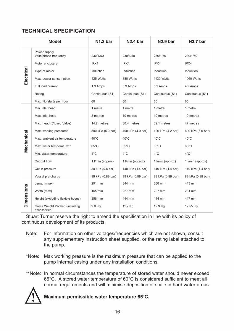
TECHNICAL SPECIFICATION
Model N1.3 bar N2.4 bar N2.9 bar N3.7 bar
Ele
ctri
cal
Power supply
Volts/phase frequency
Motor enclosure
Type of motor
Max. power consumption
Full load current
Rating
Max. No starts per hour
230/1/50
IPX4
Induction
425 Watts
1.9 Amps
Continuous (S1)
60
230/1/50
IPX4
Induction
880 Watts
3.9 Amps
Continuous (S1)
60
230/1/50
IPX4
Induction
1130 Watts
5.2 Amps
Continuous (S1)
60
230/1/50
IPX4
Induction
1060 Watts
4.9 Amps
Continuous (S1)
60
Mec
han
ical
Min. inlet head
Max. inlet head
Max. head (Closed Valve)
Max. working pressure*
Max. ambient air temperature
Max. water temperature**
Min. water temperature
Cut out flow
Cut in pressure
Vessel pre-charge
1 metre
8 metres
14.2 metres
500 kPa (5.0 bar)
40°C
65°C
4°C
1 l/min (approx)
80 kPa (0.8 bar)
89 kPa (0.89 bar)
1 metre
10 metres
30.4 metres
400 kPa (4.0 bar)
40°C
65°C
4°C
1 l/min (approx)
140 kPa (1.4 bar)
89 kPa (0.89 bar)
1 metre
10 metres
32.1 metres
420 kPa (4.2 bar)
40°C
65°C
4°C
1 l/min (approx)
140 kPa (1.4 bar)
89 kPa (0.89 bar)
1 metre
10 metres
47 metres
600 kPa (6.0 bar)
40°C
65°C
4°C
1 l/min (approx)
140 kPa (1.4 bar)
89 kPa (0.89 bar)
Dim
ensi
ons
Length (max)
Width (max)
Height (excluding flexible hoses)
Gross Weight Packed (including
accessories)
291 mm
165 mm
356 mm
9.0 Kg
344 mm
227 mm
444 mm
11.7 Kg
368 mm
227 mm
444 mm
12.9 Kg
443 mm
231 mm
447 mm
12.55 Kg
Stuart Turner reserve the right to amend the specification in line with its policy of
continuous development of its products.
Note: For information on other voltages/frequencies which are not shown, consult
any supplementary instruction sheet supplied, or the rating label attached to
the pump.
*Note: Max working pressure is the maximum pressure that can be applied to the
pump internal casing under any installation conditions.
**Note: In normal circumstances the temperature of stored water should never exceed
65°C. A stored water temperature of 60°C is considered sufficient to meet all
normal requirements and will minimise deposition of scale in hard water areas.
Maximum permissible water temperature 65°C.
- 17 -
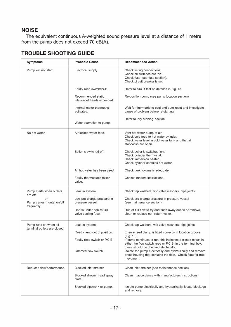
NOISEThe equivalent continuous A-weighted sound pressure level at a distance of 1 metre
from the pump does not exceed 70 dB(A).
TROUBLE SHOOTING GUIDE
Symptoms Probable Cause Recommended Action
Pump will not start. Electrical supply.
Faulty reed switch/PCB.
Recommended static
inlet/outlet heads exceeded.
Internal motor thermotrip
activated.
Water starvation to pump.
Check wiring connections.
Check all switches are ‘on’.
Check fuse (see fuse section).
Check circuit breaker is set.
Refer to circuit test as detailed in Fig. 18.
Re-position pump (see pump location section).
Wait for thermotrip to cool and auto-reset and investigate
cause of problem before re-starting.
Refer to ‘dry running’ section.
No hot water. Air locked water feed.
Boiler is switched off.
All hot water has been used.
Faulty thermostatic mixer
valve.
Vent hot water pump of air.
Check cold feed to hot water cylinder.
Check water level in cold water tank and that all
stopcocks are open.
Check boiler is switched ‘on’.
Check cylinder thermostat.
Check immersion heater.
Check cylinder contains hot water.
Check tank volume is adequate.
Consult makers instructions.
Pump starts when outlets
are off.
or
Pump cycles (hunts) on/off
frequently.
Leak in system.
Low pre-charge pressure in
pressure vessel.
Debris under non-return
valve sealing face.
Check tap washers, w/c valve washers, pipe joints.
Check pre-charge pressure in pressure vessel
(see maintenance section).
Run at full flow to try and flush away debris or remove,
clean or replace non-return valve.
Pump runs on when all
terminal outlets are closed.
Leak in system.
Reed clamp out of position.
Faulty reed switch or P.C.B.
Jammed flow switch.
Check tap washers, w/c valve washers, pipe joints.
Ensure reed clamp is fitted correctly in location groove
(Fig. 18).
If pump continues to run, this indicates a closed circuit in
either the flow switch reed or P.C.B. in the terminal box,
these should be checked electrically.
Isolate the pump electrically and hydraulically and remove
brass housing that contains the float. Check float for free
movement.
Reduced flow/performance. Blocked inlet strainer.
Blocked shower head spray
plate.
Blocked pipework or pump.
Clean inlet strainer (see maintenance section).
Clean in accordance with manufacturers instructions.
Isolate pump electrically and hydraulically, locate blockage
and remove.
- 18 -
Dry Run ProtectionThis pump is fitted with a safety control circuit, which will detect the following fault
condition:
� Dry running caused by water starvation to the pump.
Should the pump run out of water it will stop as part of a “protective logic sequence”,
detailed below.
The fault should be rectified before re-starting the pump. Check that there is sufficient
water supply to the pump and also ensure that all terminal fitting outlets are closed.
Protective Logic SequenceIf water starvation occurs and the power supply to the pump remains uninterrupted, the
pump controller will perform the following protective sequence.
1. If the pump detects water starvation, it will stop operation after a 1 minute period.
2. The pump will remain in the off condition for a period of 5 minutes.
3. The pump will then re-start and if the water starvation condition remains present, the
pump will then stop operation after a 1 minute period.
4. The pump will remain in the off condition for a period of 5 minutes.
5. The pump will then re-start and if the water starvation condition remains present, the
pump will then stop operation after a 1 minute period.
6. The pump will remain in the off condition for a period of 5 minutes.
7. The pump will then re-start and if the water starvation condition remains present, the
pump will then stop operation after a 1 minute period.
8. After three consecutive resets are performed the pump will remain in the off
condition indefinitely.
9. To restart the pump, the power supply should be first isolated for a period of at least
10 seconds before switching on again.
If the pump fails to operate normally after three attempts to re-start, then please consult
Stuart Turner on 01491 572655.
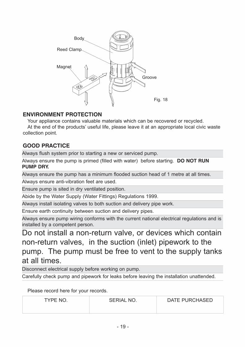
Flow Switch Circuit Test1. First confirm visually that the flow switch reed clamp has not been dislodged during
handling or installation. The clamp must be fully located within its flow switch
body groove as shown.
2. To carry out the following test you will need to obtain a magnet, a typical fridge
magnet is suitable.
3. Ensure the power supply is switched on.
4. Position the magnet directly in front of the reed clamp as shown. If pump does not
start, then slowly move the magnet up and down to a position that exceeds the extent
of the reed clamp. The pump should instantaneously start at some point during this
extent of movement. If this does not happen, this indicates a possible fault with the
reed switch or the P.C.B which is located within the terminal box. These should be
checked electrically. Consult Stuart Turner for further instructions.
- 19 -
ENVIRONMENT PROTECTIONYour appliance contains valuable materials which can be recovered or recycled.
At the end of the products’ useful life, please leave it at an appropriate local civic waste
collection point.
GOOD PRACTICEAlways flush system prior to starting a new or serviced pump.
Always ensure the pump is primed (filled with water) before starting. DO NOT RUNPUMP DRY.
Always ensure the pump has a minimum flooded suction head of 1 metre at all times.
Always ensure anti-vibration feet are used.
Ensure pump is sited in dry ventilated position.
Abide by the Water Supply (Water Fittings) Regulations 1999.
Always install isolating valves to both suction and delivery pipe work.
Ensure earth continuity between suction and delivery pipes.
Always ensure pump wiring conforms with the current national electrical regulations and is
installed by a competent person.
Do not install a non-return valve, or devices which contain
non-return valves, in the suction (inlet) pipework to the
pump. The pump must be free to vent to the supply tanks
at all times.Disconnect electrical supply before working on pump.
Carefully check pump and pipework for leaks before leaving the installation unattended.
Please record here for your records.
TYPE NO. SERIAL NO. DATE PURCHASED
Body
Reed Clamp
Magnet
Groove
Fig. 18

Issue No .0709/1-02 Pt. No. 19106
YOUR 2 YEAR GUARANTEEMonsoon Pumps are guaranteed by Stuart Turner Limited to be free from defects in
materials or workmanship for 2 years from the date of purchase. Within the guarantee
period we will repair, free of charge, any defects in the pump resulting from faults in
material or workmanship repairing, exchanging parts or exchanging the whole unit as we
may choose.
Not covered by this guarantee: Damage arising from improper use, unauthorised repair,
normal wear and tear and defects which have a negligible effect on the value or operation
of the pump.
Reasonable evidence must be supplied that the product has been purchased within 2
years prior to the date of claim.
This guarantee is in addition to the purchaser's rights under any legislation presently in
force.
In the event of a claim please telephone Stuart Turner Ltd on 01491 572655 or return
pump with accessories removed, pipes etc.
Proof of purchase should accompany the returned unit to avoid delay in action.
Stuart Turner Ltd, Henley-on-Thames, Oxfordshire RG9 2AD ENGLAND
Tel: +44 (0) 1491 572655, Fax: +44 (0) 1491 573704
email: [email protected] web: www.stuart-turner.co.ukV.A.T. REG. No. 199 0987 92. Registered in England No. 88368. Registered Office: Market Place, Henley-on-Thames
DECLARATION OF CONFORMITY
98/37/ECBS EN ISO 12100-1, BS EN ISO 12100-2, BS EN 809
2006/95/ECBS EN 60335-1, BS EN 60335-2-41, EN 50366
89/336/EECBS EN 55014-1, BS EN 55014-2, BS EN 55022, BS EN 61000-3-2, BS EN 61000-3-3,
BS EN 61000-4-2, BS EN 61000-4-3, BS EN 61000-4-4, BS EN 61000-4-5, BS EN 61000-4-6,
BS EN 61000-4-11
IT IS HEREBY CERTIFIED THAT THE STUART ELECTRIC MOTOR DRIVEN PUMP AS
SERIAL NUMBER BELOW, COMPLIES WITH THE ESSENTIAL REQUIREMENTS OF THE
ABOVE E.E.C. DIRECTIVES.
RESPONSIBLE PERSON
AND MANUFACTURER STUART TURNER LIMITED
HENLEY-ON-THAMES, OXFORDSHIRE
RG9 2AD ENGLAND.
Signed . . . . . . . . . . . . . . . . . . . . . . . . . . . . . . . . . . . . . . . Customer Relationship Manager
Stuart Turner are an approved company to BS EN ISO 9001:2000