Embed Size (px)
Citation preview
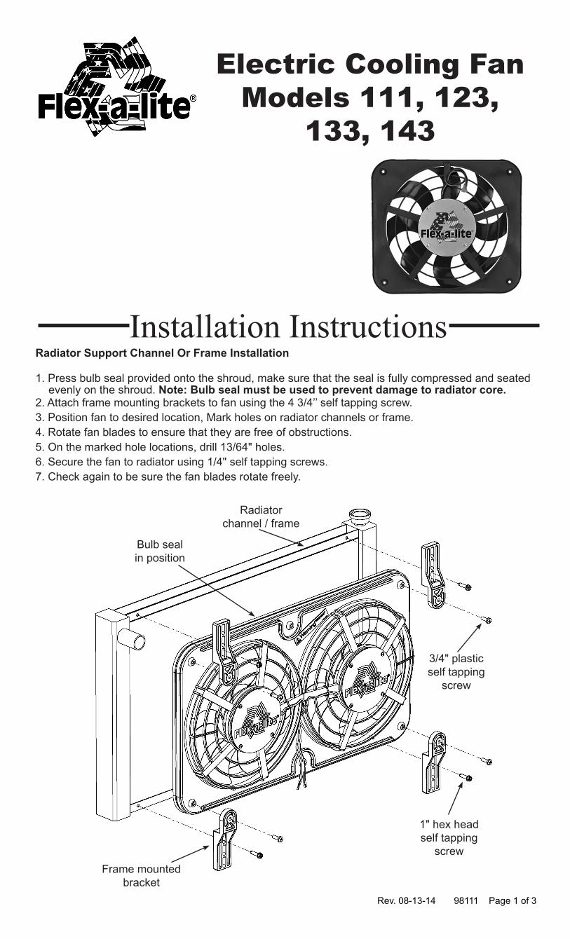
Radiator Support Channel Or Frame Installation
1. Press bulb seal provided onto the shroud, make sure that the seal is fully compressed and seated evenly on the shroud. Note: Bulb seal must be used to prevent damage to radiator core.
2. Attach frame mounting brackets to fan using the 4 3/4’’ self tapping screw.3. Position fan to desired location, Mark holes on radiator channels or frame.4. Rotate fan blades to ensure that they are free of obstructions.5. On the marked hole locations, drill 13/64" holes.6. Secure the fan to radiator using 1/4" self tapping screws.7. Check again to be sure the fan blades rotate freely.
Electric Cooling FanModels 111, 123,
133, 143
Rev. 08-13-14 98111 Page 1 of 3
Installation Instructions
Radiatorchannel / frame
3/4" plasticself tapping
screw
1" hex headself tapping
screwFrame mounted
bracket
Bulb sealin position
Wiring Instructions Model 111&133
Step 1: Locate mounting point for the control unitLocate a mounting point for the control box near inlet side of the radiator. The control unit needs to be placed within about 18" of radiator inlet hose. The inner fender next to the radiator may be a convenient location. Attach the control unit using the screws provided.
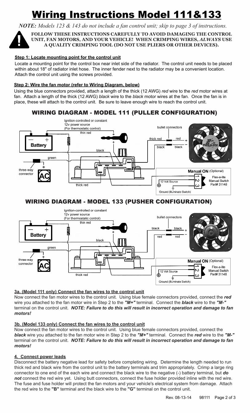
Step 2: Wire the fan motor (refer to Wiring Diagram, below)Using the blue connectors provided, attach a length of the thick (12 AWG) red wire to the red motor wires at fan. Attach a length of the thick (12 AWG) black wire to the black motor wires at the fan. Once the fan is in place, these will attach to the control unit. Be sure to leave enough wire to reach the control unit.
Rev. 08-13-14 98111 Page 2 of 3
NOTE: Models 123 & 143 do not include a fan control unit; skip to page 3 of instructions.
3a. (Model 111 only) Connect the fan wires to the control unit Now connect the fan motor wires to the control unit. Using blue female connectors provided, connect the red wire you attached to the fan motor wire in Step 2 to the "M+" terminal. Connect the black wire to the "M-" terminal on the control unit. NOTE: Failure to do this will result in incorrect operation and damage to fan motors!
3b. (Model 133 only) Connect the fan wires to the control unit Now connect the fan motor wires to the control unit. Using blue female connectors provided, connect the black wire you attached to the fan motor wire in Step 2 to the "M+" terminal. Connect the red wire to the "M-" terminal on the control unit. NOTE: Failure to do this will result in incorrect operation and damage to fan motors!
4. Connect power leadsDisconnect the battery negative lead for safety before completing wiring. Determine the length needed to run thick red and black wire from the control unit to the battery terminals and trim appropriately. Crimp a large ring connector to one end of the each wire and connect the black wire to the negative (-) battery terminal, but do not connect the red wire yet. Using butt connectors, connect the fuse holder provided inline with the red wire. The fuse and fuse holder will protect the fan motors and your vehicle's electrical system from damage. Attach the red wire to the "B" terminal and the black wire to the "G" terminal on the control unit.
FOLLOW THESE INSTRUCTIONS CAREFULLY TO AVOID DAMAGING THE CONTROL UNIT, FAN MOTORS, AND YOUR VEHICLE! WHEN CRIMPING WIRES, ALWAYS USE
A QUALITY CRIMPING TOOL (DO NOT USE PLIERS OR OTHER DEVICES).
WIRING DIAGRAM - MODEL 111 (PULLER CONFIGURATION)
WIRING DIAGRAM - MODEL 133 (PUSHER CONFIGURATION)

7. Manual Switch (Optional)For manual switch operation, use Flex-a-lite p/n 31148. Connect switch as shown on the wiring diagram (previous page). To override engine temperature and turn fan on, connect the switch to the "M" terminal on the control unit. NOTE: To prevent thermostatic activation (if only manual switch operation is desired), omit the lead to the "+" terminal of the control box. "B", "G", "M+" and "M-" must remain connected. If using a switch other than a Flex-a-lite manual switch, do not connect a ground wire to the switch!
8. Secure loose wiresUse the zip ties provided to secure the wires and prevent them from interfering with fan blades, belts, and pulleys in the engine compartment. Reconnect the battery and insert the fuse into the fuse holder.
9. Insert temperature sensor Locate the temperature sensor. Gently push probe through fins in radiator as close to the upper radiator hose as possible. The rubber insulator cap should be used when possible to insulate any of the probe coming through the front side of the radiator.
Rev. 08-13-14 98111 Page 3 of 3
Wiring Instructions 111&133 Cont'd.
Install temp. probe near inlet hose... then replace the insulator cap.
10. Adjust the temperature control knob on the control boxIf you disconnected any hoses or drained coolant to install the fan, reconnect the hoses and refill the radiator. Press the control knob (included in wiring kit) onto the control box shaft. Turn the knob clockwise until it stops. Start the engine and allow it to idle. Using a hand-held thermometer (positioned near the inlet hose) or the vehicle's temperature gauge, monitor the temperature. When the coolant temp. is slightly above normal or desired temp. is reached, turn the knob counter-clockwise just until the fan turns on. From now on, the fan should activate at this temperature setting. Adjust as necessary to maintain desired temperature.
Wiring Instructions - Model 123 & 1431a.(Model 123 only): Wire the fan motors to power source (control unit or switch and relay if desired). Connect the red wires from the fan motor to a 12v. positive (+) source. Connect the black motor wires to a ground (-) source. NOTE: Failure to do this will result in incorrect operation and damage to the fan motors!
1b.(Model 143 only): Wire the fan motors to power source (control unit or switch and relay if desired). Connect the black wires from the fan motor to a 12v. positive (+) source. Connect the red motor wires to a ground (-) source. NOTE: Failure to do this will result in incorrect operation and damage to the fan motors!
2. Connect the fuse holder. Be sure to connect the provided fuse holder in-line with the positive (+) power wire to protect the fan motors and your vehicle's electrical system from damage.
6. Fan operation with air conditioning (if equipped)Locate the wires coming from the A/C compressor. Determine which wire is ground and which is positive by using a volt meter. Connect the positive wire to the supplied thin green wire by use of a piggyback connector. Determine length needed to reach the control unit and trim to length. Attach a pink female connector to the end of the wire and attach it to the "C" terminal on the control unit.
5. Ignition controlled power source Locate fuse box. Find a circuit that is "hot " when the key is in the "ON" position. NOTE: DO NOT use the DRL or brake/taillight fuse! Attach the included fuse tap to fuse. Attach a female connector to the thin red wire included and connect to the fuse tap. Trim the wire so that it will reach the control unit. Attach a pink female connector to end of wire and connect to the "+" terminal on the control unit.
The Flex-a-lite Limited WarrantyFlex-a-lite Consolidated, 7009-45th St. Ct. E. Fife, WA 98424, Telephone No. 253-922-2700, warrants to the original purchasing user, that all Flex-a-lite products to be free of defects in material and workmanship for a period of 365 days (1 year) from date of purchase. Flex-a-lite products failing within 365 days (1 year) from date of purchase may be returned to the factory through the point of purchase, transportation charges prepaid. If, on inspection, cause of failure is determined to be defective material or workmanship and not by misuse, accidental or improper installation, Flex-a-lite will replace the product free of charge, transportation prepaid. Flex-a-lite will not be liable for incidental, progressive or consequential damages. Some states do not allow the exclusion or limitation of incidental or consequential damages, so the above limitation or exclusion may not apply to you. This warranty gives you specific legal rights and you may have other rights, which vary from state to state. The Flex-a-lite warranty is in compliance with the Magnuson-Moss Warranty Act of 1975.