Embed Size (px)
Citation preview
ActiveSmart™ Slide-in refrigerator
RS90A and RS90AU models
NZ AU GB IE EU AE HK SG IN
INSTALLATION INSTRUCTIONS
839137 A 02.15
www.fisherpaykel.com


1
1 SAfEty ANd wArNINGS
ImpORTANT!SAVE THESE INSTRUCTIONSThe models shown in this installation guide may not be available in all markets and are subject to change at any time. For current details about model and specification availability in your country, please go to our website www.fisherpaykel.com or contact your local Fisher & Paykel dealer.
2 BEforE INStAllAtIoN
Please follow the installation steps below to ensure your appliance is installed and operates correctly.
Power
●● The appliance must be installed so the plug is accessible.●● To ensure that the appliance is not accidently switched off, connect your refrigerator to its
own isolating switch. Do not plug in any other appliance at this isolating switch.●● For power requirements, refer to the information on the serial plate. This is located at the
front right-hand side of the drawer when open.●● It is essential that the appliance is properly grounded (earthed).●● Connect the appliance to the electrical supply (220V – 240V 50Hz) with the fitted plug
and lead.●● Connections to the mains supply should be in accordance with local regulations.
location
●● Your refrigerator should not be located in direct sunlight or next to any heat generating appliance such as a cooktop, oven or dishwasher.
●● This appliance is intended to be used in household and similar applications such as– Staff kitchen areas in shops, offices, and other working environments;– Domestic farm houses and by clients in hotels, motels and other residential type
environments;– Domestic bed and breakfast type environments;– Domestic catering and similar non-retail/non-commercial applications.
Ice & water models only
●● Your Ice & Water refrigerator must be installed by an authorised plumber or Fisher & Paykel Authorised Repairer as incorrect plumbing can lead to water leaks.
●● Fisher & Paykel Appliances does not accept responsibility for damage (including water damage) caused by faulty installation or plumbing.
optional accessories kit
●● The standard appliance does not include door panels. To complete the integrated appliance the customer should supply their own. All the hardware required to mount these door panels to the refrigerator doors is supplied.
●● When designing custom door panels, these are only available for non-Ice & Water models.●● Standard Fisher & Paykel kits are available (EZKleen stainless steel door panels, part
numbers: RD90U or RD90), and can be purchased through Fisher & Paykel Customer Care Centre or online at www.fisherpaykel.com (this service is available to selected markets only).
r600a
this refrigerator contains flammable refrigerant isobutane (r600a).
! wArNING!Electric Shock Hazardread and follow the safety and warnings outlined in this installation guide before operating this appliance.failure to do so can result in death, electric shock, fire or injury to persons.
! wArNING!Cut Hazardtake care – panel edges are sharp. failure to use caution could result in injury or cuts.
! wArNING!• this appliance is top-heavy and must
be secured to prevent the possibility of tipping forward.
• to ensure that the appliance is stable under all loading conditions, the anti-tip bracket supplied can be installed according to the following installation instructions.
2
3 ComPoNENtS lISt
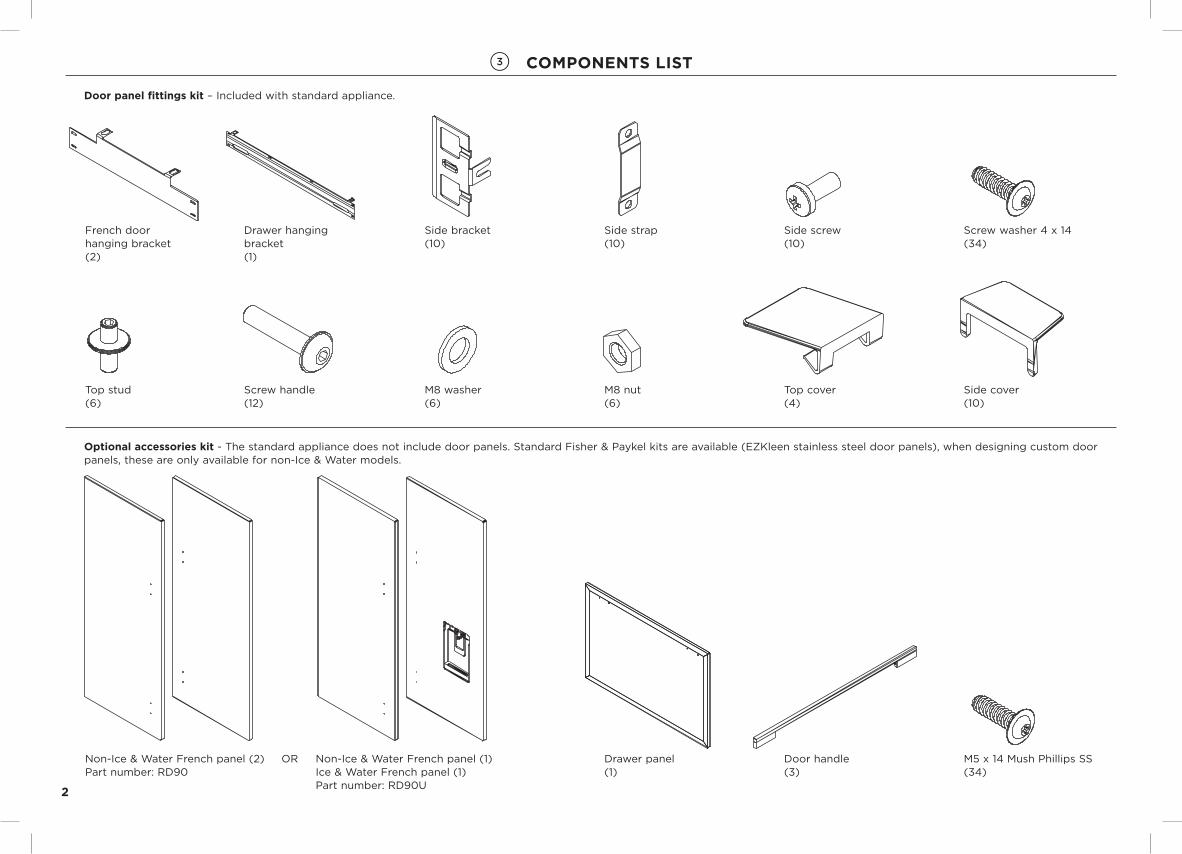
French door hanging bracket(2)
Drawer hanging bracket(1)
Side bracket(10)
Side strap(10)
Top stud(6)
Side cover(10)
Top cover(4)
Screw handle(12)
Side screw(10)
Drawer panel(1)
Door handle(3)
M8 nut(6)
M8 washer(6)
door panel fittings kit – Included with standard appliance.
optional accessories kit - The standard appliance does not include door panels. Standard Fisher & Paykel kits are available (EZKleen stainless steel door panels), when designing custom door panels, these are only available for non-Ice & Water models.
Non-Ice & Water French panel (1)Ice & Water French panel (1)Part number: RD90U
Non-Ice & Water French panel (2) Part number: RD90
Screw washer 4 x 14(34)
OR M5 x 14 Mush Phillips SS(34)

3
3 ComPoNENtS lISt
Anti-tip bracket(1)
Phillips screw(4)
Masonry plug(4)
Kickstrip grille(1)
Kickstrip filter(1)
Wood screw(2)
Water filter cartridge (1) Part number: 839041
Collet locking key(1)
Filter cartridge tool(1)
Product kit - Included with standard appliance.
Ice & water kit – Included with standard Ice & Water models only.
External display module(1)
Power cord clip (1)
Anti-tip bracket kit – Included with standard appliance.
Adaptor tap ¼” OD x ½” BSP thread(1)
4
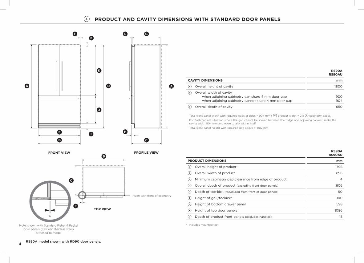
4 ProdUCt ANd CAvIty dImENSIoNS wItH StANdArd door PANElS
RS90A model shown with RD90 door panels.
rS90A rS90AU
CAvIty dImENSIoNS mm
A Overall height of cavity 1800
B Overall width of cavity when adjoining cabinetry can share 4 mm door gap when adjoining cabinetry cannot share 4 mm door gap
900 904
C Overall depth of cavity 650
Total front panel width with required gaps at sides = 904 mm ( E product width + 2 x F cabinetry gaps).
For flush cabinet situation where the gap cannot be shared between the fridge and adjoining cabinet, make the cavity width 904 mm and open totally within itself.
Total front panel height with required gap above = 1802 mm
rS90A rS90AU
ProdUCt dImENSIoNS mm
D Overall height of product* 1798
E Overall width of product 896
F Minimum cabinetry gap clearance from edge of product 4
G Overall depth of product (excluding front door panels) 606
H Depth of toe-kick (measured from front of door panels) 50
I Height of grill/toekick* 100
J Height of bottom drawer panel 598
K Height of top door panels 1096
L Depth of product front panels (excludes handles) 18
* Includes mounted feet
toP vIEw
E
B
H
C
ADA
J
I
L G
C
B
F
F
F
K
4
Flush with front of cabinetry
Note: shown with Standard Fisher & Paykel door panels (EZKleen stainless steel)
attached to fridge.
E
B
H
C
ADA
J
I
L G
C
B
F
F
F
K
4
froNt vIEw ProfIlE vIEw
5
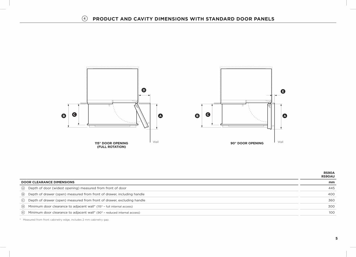
4 ProdUCt ANd CAvIty dImENSIoNS wItH StANdArd door PANElS
rS90A rS90AU
door ClEArANCE dImENSIoNS mm
A Depth of door (widest opening) measured from front of door 445
B Depth of drawer (open) measured from front of drawer, including handle 400
C Depth of drawer (open) measured from front of drawer, excluding handle 360
D Minimum door clearance to adjacent wall* (115° – full internal access) 300
E Minimum door clearance to adjacent wall* (90° – reduced internal access) 100
* Measured from front cabinetry edge, includes 2 mm cabinetry gap.
90° DOOR OPENING115° DOOR OPENING[FULL ROTATION]
AB C
D
B C A
E
Wall Wall90° door oPENING115° door oPENING (fUll rotAtIoN)

6
5 ProdUCt ANd CAvIty dImENSIoNS wItHoUt door PANElS
RS90A model shown only. When designing custom door panels, these are only available for non-Ice & Water models.
rS90A
ProdUCt dImENSIoNS mm
D Overall height of product* 1798
E Overall width of product 890
F Minimum cabinetry gap clearance from edge of custom product** 4
G Overall depth of product (excluding front door panels) 606
H Depth of toe-kick (measured from front of door panels)*** 50
I Height of grill/toekick* 100
J Depth of product front panels (excludes handles)*** 18
* Includes mounted feet and top brackets.
** For custom door panel dimensions refer to ‘Custom door panel dimensions’ page.
*** Door panels to be manufactured and fitted by cabinetmaker, max. thickness 18 mm.
rS90A
CAvIty dImENSIoNS mm
A Overall height of cavity 1800
B Overall width of cavity when adjoining cabinetry can share 4 mm door gap when adjoining cabinetry cannot share 4 mm door gap
900 904
C Overall depth of cavity 650
Total front panel width with required gaps at sides = 904 mm ( E product width + 2 x F cabinetry gaps).
For flush cabinet situation where the gap cannot be shared between the fridge and adjoining cabinet, make the cavity width 904 mm and open totally within itself.
E
B
H
C
AA
I
J G
C
B
F
F
F
D
4
Note: Shown with custom panel attached to fridge
Note: shown with custom door panels attached to fridge
toP vIEw
Flush with front of cabinetry
E
B
H
C
AA
I
J G
C
B
F
F
F
D
4
Note: Shown with custom panel attached to fridge
ProfIlE vIEwfroNt vIEw

7
5 ProdUCt ANd CAvIty dImENSIoNS wItHoUt door PANElS
rS90A
door ClEArANCE dImENSIoNS mm
A Depth of door (widest opening) measured from front of cabinetry 445
B Depth of drawer (open) measured from front of cabinetry* 338
C Minimum door clearance** to adjacent wall (115° – full internal access)* 300
D Minimum door clearance** to adjacent wall (90° – reduced internal access)* 100
* Does not include the custom door panels or handles to be manufactured and fitted by cabinetmaker.
** Measured from front cabinetry edge, includes 2 mm cabinetry gap.
90° DOOR OPENING115° DOOR OPENING[FULL ROTATION]
AB
C
B A
D
Wall Wall90° door oPENING115° door oPENING
(fUll rotAtIoN)
8
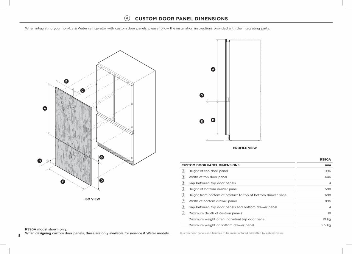
6 CUStom door PANEl dImENSIoNS
When integrating your non-Ice & Water refrigerator with custom door panels, please follow the installation instructions provided with the integrating parts.
ISO VIEW
H
F D
g
A
B
C
PROFILE VIEW
D
g
A
E
ProfIlE vIEw
ISO VIEW
H
F D
g
A
B
C
PROFILE VIEW
D
g
A
E
ISo vIEw
rS90A
CUStom door PANEl dImENSIoNS mm
A Height of top door panel 1096
B Width of top door panel 446
C Gap between top door panels 4
D Height of bottom drawer panel 598
E Height from bottom of product to top of bottom drawer panel 698
F Width of bottom drawer panel 896
G Gap between top door panels and bottom drawer panel 4
H Maximum depth of custom panels 18
Maximum weight of an individual top door panel 10 kg
Maximum weight of bottom drawer panel 9.5 kg
Custom door panels and handles to be manufactured and fitted by cabinetmaker.RS90A model shown only. When designing custom door panels, these are only available for non-Ice & Water models.

9
7 CUStom door PANEl PrEPArAtIoNS
The following drawings apply to non-Ice & Water models only. Dimensions are shown in Metric (mm) and apply for the preparation and installation of custom door panels.For Dwg and Dxf files of the below panel preparation download the folder on http://thekitchentools.fisherpaykel.com
toP PANEl – rEAr vIEw
CUSTOM PANEL PREPARATION
TOP PANEL – REAR VIEW
Note: Dimensions are shown in Metric (mm)Dimensions apply for the preparation and installation of custom panels.For the second panel mirror and repeat dimensions using inner bottom corner as the reference point.
Dwg and Dxf files of the above panel preparation download the folder on http://thekitchentools.fisherpaykel.com
392.3
54.8
35
297.4
50
457.5
50
126.1
34.7
414
R1.25 REF 12x Pilot holes recommended for bracket attachment.(Do not penetrate front surface).
All measurements to be made from inner bottom corner. For the second panel mirror and repeat dimensions using inner bottom corner as the reference point.
CUSTOM PANEL PREPARATION
BOTTOM PANEL – REAR VIEW
Note: Dimensions are shown in Metric (mm)Dimensions apply for the preparation and installation of custom panels.
Dwg and Dxf files of the above panel preparation download the folder on http://thekitchentools.fisherpaykel.com
385
128
29.158.1
492
416
50
58.1
R1.25 REF 10x Pilot holes recommended for bracket attachment. (Do not penetrate front surface).
Bottom PANEl – rEAr vIEw
Handle details
Top Panel – Ensure handle is mounted 65.03 mm from inner edge of panel to the centre – this will avoid interference with brackets.Bottom Panel – Ensure handle screw heads are counter sunk into back of panel to avoid interfering with hanging bracket.

10
8 CAvIty PrEPArAtIoN
rS90A rS90AU
CAvIty dImENSIoNS mm
A Overall height of cavity 1800
B Overall width of cavity 900
C Overall depth of cavity 650
rS90A rS90AU
ElECtrICAl SPECIfICAtIoNS
Supply 230 VAC, 50 Hz 230 VAC, 50 Hz
Service 10 amp circuit 10 amp circuit
PlUmBING SPECIfICAtIoNS
Supply – ½” BSP threaded water connection 6.35 mm PEX tubing
Pressure – Minimum 22 psi (150 kPa) Maximum 120 psi (827 kPa) @ 20°C
Note: recommended that the electrical & water connection be located in an adjacent cabinet to either side of the fridge or above the fridge cavity.
Do not locate water or electricity in this area, keep clear of connections.
CAuTIoN: central area can only fit water outlet and electrical plug if they are placed within a recessed cavity.
* In this location the water tap needs to be recessed into the wall, the recess must allow for an 80 mm bend radius for the water tube.
!!
130
72
100
355145
100
!
A
C
B
REAR VIEW OF CAVITY
Alternative area above cavity for connections
ElectricalPlumbing
ElectricalPlumbing
rEAr vIEw of CAvIty
130
72
100
355145
100
!
A
C
B
REAR VIEW OF CAVITY
Left side of cavity
Floor
optional electrical and water connection location*

11
9 mAxImUm dIStANCE of HoSES ANd Cord
* Applies to Ice & Water models with Fisher & Paykel door panels only.
Power cord (excl.plug) – 2050 mm
Water inlet hose* – 3930 mm
rIGHt HANd SIdE
Power cord (excl.plug) – 2050 mm
Water inlet hose* – 3180 mm
lEft HANd SIdE
Water inlet hose* – 2250 mm Power cord (excl.plug) – 800 mm

12
!0 ANtI-tIP BrACKEt INStAllAtIoN
Safety requires refrigerators be stable when doors and/or drawer, are open. Depending on your installation enclosure, an anti-tip bracket may need to be fitted if the ceiling/cabinetry above the enclosure is not secured to the wall (to withstand a 100 kg load). This will prevent the possibility of the appliance tipping forward, when doors and/or drawer, are open.
ImpORTANT!when fastening with masonry plugs and/or screws:
●● Ensure the screws avoid electrical, gas and water conduits.●● Ensure the surface the bracket is fastened to withstand a 100 kg load.●● Ensure light-weight masonry material such as cinder block and new concrete (no curing time) are not used in installation.●● do not use metallic materials that may corrode, stain and/or damage the enclosure.
If a minimum 60 mm overlap cannot be achieved we recommend fastening a solid spacer (wooden beam etc.) behind the bracket.
1 Ensure the length of the spacer corresponds to the enclosure’s width. Always secure the spacer to existing studs on the enclosure wall.
3 Hammer masonry plugs into the wall until flush.Fix bracket to the wall with Phillips screws x 4. Ensure screws hold tight.
2 Fix bracket to the wall with Phillips screws x 4. Ensure screws hold tight and the bracket overlaps the appliance when it is positioned (60 mm min.) for a secure hold.
woodEN wAll INStAllAtIoN SolId wAll INStAllAtIoN
A
If greater than 100 mm, an anti-tip bracket is required
60 mm min. overlap
Bracket
ProfIlE vIEw
1 Project the top front edge of the finished enclosure to the centre of the back wall, this will locate the top of the anti-tip bracket (refer to A).
2 Mark screw locations to drill Ø6.0 mm x 35 mm deep holes.
60 mm min. overlap
Spacer
Bracket
ProfIlE vIEw
2 Fix bracket to the spacer with Phillips screws x 4. Ensure screws hold tight and the bracket overlaps the appliance when it is positioned (60 mm min.) for a secure hold.
1 Project the top front edge of the finished enclosure to the centre of the back wall, this will locate the top of the anti-tip bracket (refer to A). Ensure a structural beam/wall stud closest to the centre of the wall enclosure is located.
SPACEr INStAllAtIoN

13
!1 CoNNECtING wAtEr SUPPly (ICE & wAtEr modElS oNly)
!2 INStAllING yoUr APPlIANCE
●● Your product is fitted with front and rear rollers designed for moving the product in the forwards and backwards direction.●● Avoid moving the product in a sideways direction as this may damage the rollers or the floor covering/surface.
ImpORTANT!●● the water connection to your Ice & water refrigerator must be installed by an authorized plumber or fisher & Paykel Authorised repairer.●● the water connection instructions below are intended only for the professional installer.●● Use only the new tubings supplied with the refrigerator. old tubings should not be used.●● do Not use with water that is microbiologically unsafe or of unknown quality without adequate disinfection before or after the system.●● wArNING – connect to potable water supply only.●● do Not install on line pressure above 120 psi (827 kPa) or below 22 psi (150 kPa).●● do Not use on hot water supply (100°f [38°C max.]).●● AvoId contamination of pipes during installation.
1 Ensure the refrigerator is NOT plugged into a power supply.
Locate isolation tap for water connection – cold water supply only. Tee and tap fitting not supplied.
2
3
4
4 Fasten the faucet connection to the cold water supply tap. Take care not to over-tighten the tap connection.
Note: the faucet connection supplied should fit most installation situations.
Turn isolating tap on and check that all connections are dry and free of drips.
5 Centre the appliance within the alcove, using the adjacent walls as a guide.
DETAIL BSCALE 1 : 5
1 Adhere power cord clip to the appliance rear. Connect the appliance to a power supply and turn on.
2 Ensure excess power cord length is secured onto the clip.
4 Ensure a firm contact is observed as the appliance engages the anti-tip bracket (60 mm min. overlap).
3 Gently push the appliance into the enclosure. Take care not to roll over or damage power cord and/or water tubing.
ImpORTANT!Ensure water tubing is routed away from any sharp objects, sharp corners (beware of kinking the tube as this will stop water flow), and not in a location where it can be kinked or squashed.
2 Uncoil the tubing from the back of the product. Firmly insert tubing to faucet connection. The tube should push in at least 16 mm before reaching the stop.
Pull gently on tubing to ensure it is locked in.
3 Secure connection by attaching the locking key in between the faucet connection and locking collet.

!3 rEmovING HINGE ENd CAPS
!4 lEvEllING yoUr APPlIANCE
●● It is important that all four corners of the product is supported firmly onto the floor to eliminate any movement.
●● Installing the appliance on a soft or uneven/unlevelled floor may result in twisting of the product and poor door sealing.
●● Raise the product using an 11 mm hex socket or 4 mm hex Allen key. One turn of height adjusting nuts is equivalent to 1 mm height travel.Note: maximum torque travel 20 mm.
1 Carefully open the French doors and remove hinge end caps.
2 Left hinge end capHold onto the corner of the end cap, firmly push to the right to disengage securing hook and pull down.
3 Pull cap gently towards the left hinge to remove.
4 Right hinge end cap Press on the centre of the end cap
and push towards the right hinge to remove.
1 Raise the front of the product until the fixing brackets contact the ceiling of the enclosure (refer to B).
Turn clockwise to raise roller or counter-clockwise to lower roller.
repeat on opposite side.
2 Raise the rear of the product until the refrigerator doors are flush with the front face of adjacent walls.
Turn clockwise to raise roller or counter-clockwise to lower roller.
repeat on the opposite side.
Gently push the front of the product to check the stability and to ensure side gaps are even with enclosure.
B
Reserve end hinge cap for later installation
Reserve end hinge cap for later installation.
14

15
!5 ASSEmBlING All door PANElS
●● Ensure door panel dimensions are correct for your appliance.●● The assembly of standard Fisher & Paykel kits (EZKleen stainless steel door panels) and custom door panels are outlined below. For standard Fisher & Paykel kits, only remove the protective film
for handle installation. This will protect the finish of the door panels until installation is complete.
french door panel
1 Mounting handleFor Fisher & Paykel kits, remove plastic plugs from handle pilot holes on panel x4. Align handle to holes and secure with screw handle x4
For custom panels, ensure handle is mounted 65.03 mm from inner edge of panel to the centre – this will avoid interference with brackets.
2 Hanging bracketFor Fisher & Paykel kits, align bracket to pilot holes and secure with M5 x 14 Mush Phillips SS x4.
For custom panels, secure bracket with screw washer x4.
3 Side brackets and strapsFor Fisher & Paykel kits, align bracket and strap to pilot holes on the sides of the panel. Secure with M5 x 14 Mush Phillips SS x2.
For custom panels, secure bracket with screw washer x2.
Repeat this process for the remaining brackets and straps x4 French door panel.
Repeat this process for the next French door panel.
drawer panel
4 Mounting handleFor Fisher & Paykel kits, remove plastic plugs from handle pilot holes on panel x4. Align handle to holes and secure with screw handle x4
For custom panels, ensure handle screw heads are counter sunk into back of panel to avoid interfering with hanging bracket.
5 Hanging bracketFor Fisher & Paykel kits, align bracket to pilot holes and secure with M5 x 14 Mush Phillips SS x6.
For custom panels, secure bracket with screw washer x6.
6 Side brackets and strapsFor Fisher & Paykel kits, align bracket and strap to pilot holes on the sides of the panel. Secure with M5 x 14 Mush Phillips SS x2.
For custom panels, secure bracket with screw washer x2.Repeat this process for the remaining brackets and straps.
16
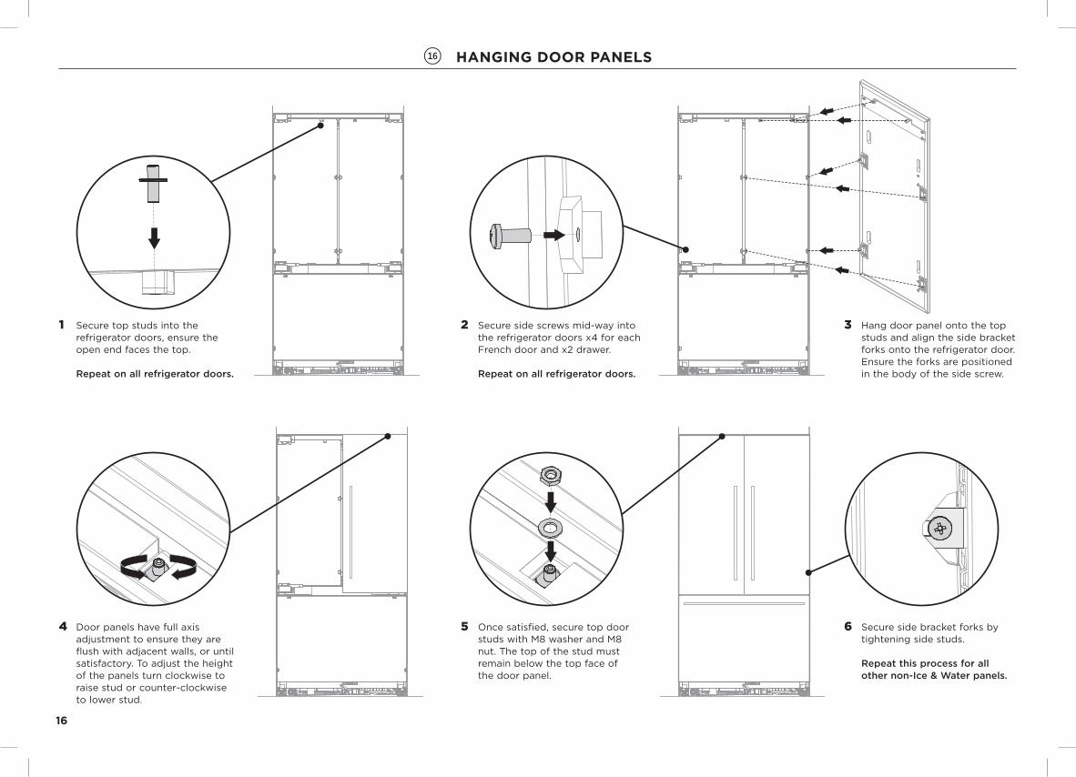
!6 HANGING door PANElS
1 Secure top studs into the refrigerator doors, ensure the open end faces the top.
Repeat on all refrigerator doors.
3 Hang door panel onto the top studs and align the side bracket forks onto the refrigerator door. Ensure the forks are positioned in the body of the side screw.
5 Once satisfied, secure top door studs with M8 washer and M8 nut. The top of the stud must remain below the top face of the door panel.
6 Secure side bracket forks by tightening side studs.
Repeat this process for all other non-Ice & Water panels.
2 Secure side screws mid-way into the refrigerator doors x4 for each French door and x2 drawer.
Repeat on all refrigerator doors.
4 Door panels have full axis adjustment to ensure they are flush with adjacent walls, or until satisfactory. To adjust the height of the panels turn clockwise to raise stud or counter-clockwise to lower stud.

17
!7 HANGING door PANElS (ICE & wAtEr modElS oNly)
7 Firmly push the water tube into the spigot behind the door panel until the marked line is not visible.
Ensure water tube is routed away from any sharp objects, sharp corners (beware of kinking the tube as this will stop water flow), and not in a location where it can be kinked or squashed when door panel is secured.
Secure door panel following the instructions on the previous page.
5 Connect display harness onto the refrigerator door by inserting firmly until you feel it clip securely.
3 Remove water tube from holder on the refrigerator door.
6 Enable the dispenser lock to prevent any water from dispensing during water connection. To lock, press the button for 4 seconds. The LED above the button will illuminate.
2 Angle top display tabs into the door panel. Ensure the harness is free of pinching. Firmly push against bottom display tabs and insert into the door panel until you feel it clip securely. Ensure the display is flush with the door panel.
1 Remove the external display module from inside the product.
Thread the display harness through the door panel cavity. Ensure the grommet is engaged.
4 Hang door panel onto the top studs. Ensure the panel is free to pivot for water connections.

18
!8 fIxING BrACKEtS ANd rEPlACING ENd HINGE CAPS
!9 INStAllING wAtEr fIltEr CArtrIdGE (ICE & wAtEr modElS oNly)
ImpORTANT!the water filter head must be firmly pushed into the product and secured, incorrect installation can lead to water leaks.
3 Turn 90° clockwise to tighten. Remove filter cartridge tool and close freezer drawer.
1 Secure fixing bracket hole to the ceiling of the enclosure with wood screw x1.
repeat on the opposite side.
3 Hold onto the corner of the end cap, firmly push up and to the left to engage securing hook. Ensure cap is flush with the product.
4 Right hinge end capAlign hinge cap to product. Press and firmly slide the cap to the left. Ensure cap is flush with the product
2 Pull freezer drawer slightly open to fit filter cartridge tool.
Align the filter cartridge tool over the filter. Insert the filter cartridge and tool into the bottom left of the product, firmly push the cartridge in until the filter head cannot be pushed any further.
1 Remove the red protective cap on the spigot head.
2 Left hinge end capAlign hinge cap to the product. Press and firmly slide the cap to the right.
4 Filter cartridge shown in the locked position.
19
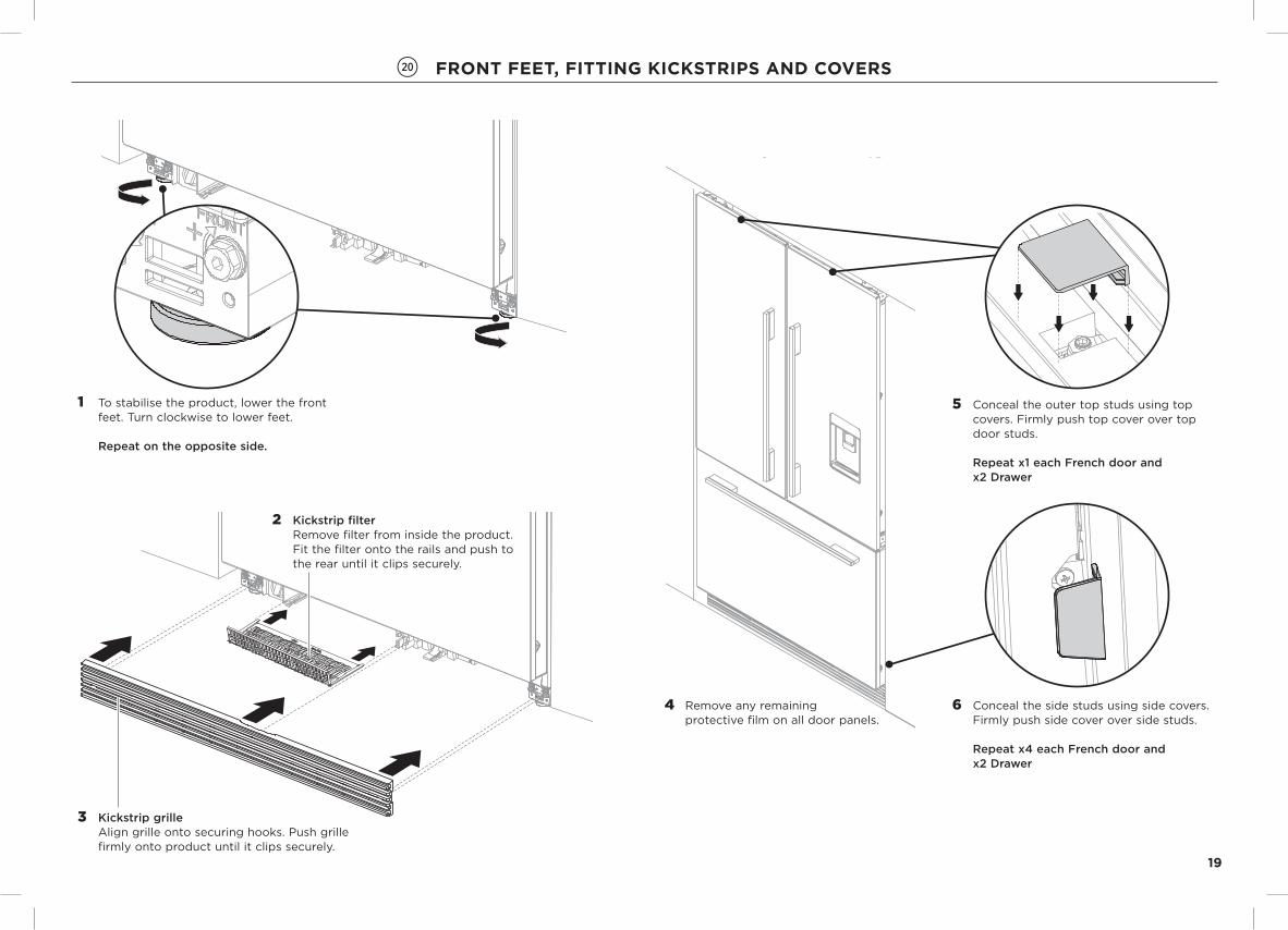
@0 froNt fEEt, fIttING KICKStrIPS ANd CovErS
2 Kickstrip filterRemove filter from inside the product. Fit the filter onto the rails and push to the rear until it clips securely.
3 Kickstrip grille Align grille onto securing hooks. Push grille firmly onto product until it clips securely.
1 To stabilise the product, lower the front feet. Turn clockwise to lower feet.
Repeat on the opposite side.
5 Conceal the outer top studs using top covers. Firmly push top cover over top door studs.
Repeat x1 each French door and x2 Drawer
4 Remove any remaining protective film on all door panels.
6 Conceal the side studs using side covers.Firmly push side cover over side studs.
Repeat x4 each French door and x2 Drawer
20
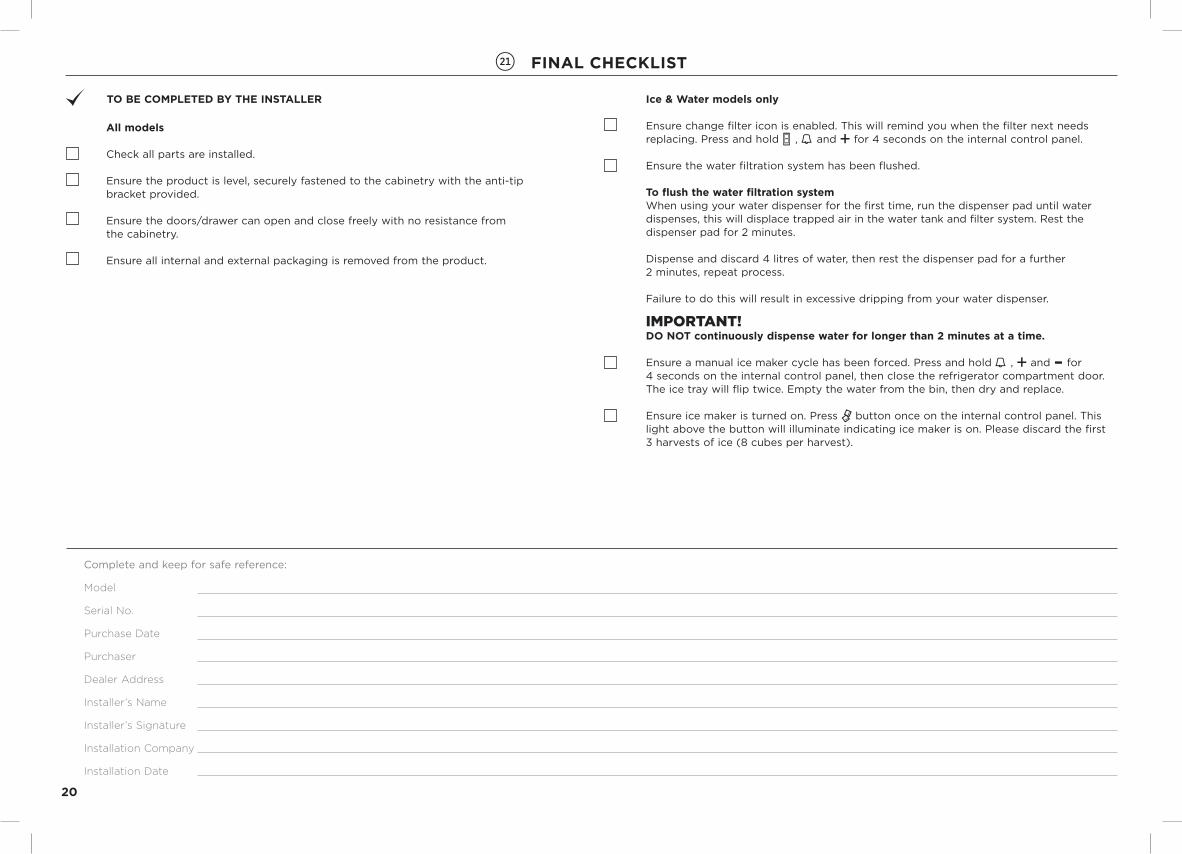
Complete and keep for safe reference:
Model
Serial No.
Purchase Date
Purchaser
Dealer Address
Installer’s Name
Installer’s Signature
Installation Company
Installation Date
to BE ComPlEtEd By tHE INStAllEr
All models
Check all parts are installed.
Ensure the product is level, securely fastened to the cabinetry with the anti-tip bracket provided.
Ensure the doors/drawer can open and close freely with no resistance from the cabinetry.
Ensure all internal and external packaging is removed from the product.
@1 fINAl CHECKlISt
Ice & water models only
Ensure change filter icon is enabled. This will remind you when the filter next needs replacing. Press and hold , and for 4 seconds on the internal control panel.
Ensure the water filtration system has been flushed.
to flush the water filtration systemWhen using your water dispenser for the first time, run the dispenser pad until water dispenses, this will displace trapped air in the water tank and filter system. Rest the dispenser pad for 2 minutes.
Dispense and discard 4 litres of water, then rest the dispenser pad for a further 2 minutes, repeat process.
Failure to do this will result in excessive dripping from your water dispenser.
ImpORTANT!do Not continuously dispense water for longer than 2 minutes at a time.
Ensure a manual ice maker cycle has been forced. Press and hold , and for 4 seconds on the internal control panel, then close the refrigerator compartment door. The ice tray will flip twice. Empty the water from the bin, then dry and replace.
Ensure ice maker is turned on. Press button once on the internal control panel. This light above the button will illuminate indicating ice maker is on. Please discard the first 3 harvests of ice (8 cubes per harvest).


839137 A 02.15
www.fisherpaykel.com
Copyright © Fisher & Paykel 2015. All rights reserved.The product specifications in this booklet apply to the specific products and models described at the date of issue. Under our policy of continuous product improvement, these specifications may change at any time. You should therefore check with your Dealer to ensure this booklet correctly
describes the product currently available.
NZ AU GB IE EU AE HK SG IN